EP3201448B1 - Gleichlaufmotor mit anordnung zur fluidströmung - Google Patents
Gleichlaufmotor mit anordnung zur fluidströmung Download PDFInfo
- Publication number
- EP3201448B1 EP3201448B1 EP14903442.3A EP14903442A EP3201448B1 EP 3201448 B1 EP3201448 B1 EP 3201448B1 EP 14903442 A EP14903442 A EP 14903442A EP 3201448 B1 EP3201448 B1 EP 3201448B1
- Authority
- EP
- European Patent Office
- Prior art keywords
- cylinder
- intake
- set forth
- piston
- ports
- Prior art date
- Legal status (The legal status is an assumption and is not a legal conclusion. Google has not performed a legal analysis and makes no representation as to the accuracy of the status listed.)
- Active
Links
- 239000012530 fluid Substances 0.000 title description 2
- 239000000446 fuel Substances 0.000 claims description 16
- 238000004891 communication Methods 0.000 claims description 6
- 230000001154 acute effect Effects 0.000 claims description 4
- 230000007423 decrease Effects 0.000 claims description 4
- 239000007789 gas Substances 0.000 description 27
- 238000002485 combustion reaction Methods 0.000 description 9
- 230000002000 scavenging effect Effects 0.000 description 6
- 238000002347 injection Methods 0.000 description 4
- 239000007924 injection Substances 0.000 description 4
- 239000000463 material Substances 0.000 description 4
- 238000000034 method Methods 0.000 description 4
- 230000008569 process Effects 0.000 description 4
- 238000006073 displacement reaction Methods 0.000 description 2
- 230000002349 favourable effect Effects 0.000 description 2
- 230000003993 interaction Effects 0.000 description 2
- 238000005086 pumping Methods 0.000 description 2
- 239000007921 spray Substances 0.000 description 2
- 230000002411 adverse Effects 0.000 description 1
- 230000009286 beneficial effect Effects 0.000 description 1
- 230000008859 change Effects 0.000 description 1
- 239000000567 combustion gas Substances 0.000 description 1
- 230000006835 compression Effects 0.000 description 1
- 238000007906 compression Methods 0.000 description 1
- 230000003247 decreasing effect Effects 0.000 description 1
- 230000000694 effects Effects 0.000 description 1
- 230000001939 inductive effect Effects 0.000 description 1
- 239000010687 lubricating oil Substances 0.000 description 1
- 238000007493 shaping process Methods 0.000 description 1
- 230000007704 transition Effects 0.000 description 1
- 239000013598 vector Substances 0.000 description 1
Images

Classifications
-
- F—MECHANICAL ENGINEERING; LIGHTING; HEATING; WEAPONS; BLASTING
- F02—COMBUSTION ENGINES; HOT-GAS OR COMBUSTION-PRODUCT ENGINE PLANTS
- F02B—INTERNAL-COMBUSTION PISTON ENGINES; COMBUSTION ENGINES IN GENERAL
- F02B25/00—Engines characterised by using fresh charge for scavenging cylinders
- F02B25/02—Engines characterised by using fresh charge for scavenging cylinders using unidirectional scavenging
- F02B25/08—Engines with oppositely-moving reciprocating working pistons
-
- F—MECHANICAL ENGINEERING; LIGHTING; HEATING; WEAPONS; BLASTING
- F02—COMBUSTION ENGINES; HOT-GAS OR COMBUSTION-PRODUCT ENGINE PLANTS
- F02B—INTERNAL-COMBUSTION PISTON ENGINES; COMBUSTION ENGINES IN GENERAL
- F02B23/00—Other engines characterised by special shape or construction of combustion chambers to improve operation
- F02B23/08—Other engines characterised by special shape or construction of combustion chambers to improve operation with positive ignition
- F02B23/10—Other engines characterised by special shape or construction of combustion chambers to improve operation with positive ignition with separate admission of air and fuel into cylinder
- F02B23/104—Other engines characterised by special shape or construction of combustion chambers to improve operation with positive ignition with separate admission of air and fuel into cylinder the injector being placed on a side position of the cylinder
-
- F—MECHANICAL ENGINEERING; LIGHTING; HEATING; WEAPONS; BLASTING
- F02—COMBUSTION ENGINES; HOT-GAS OR COMBUSTION-PRODUCT ENGINE PLANTS
- F02B—INTERNAL-COMBUSTION PISTON ENGINES; COMBUSTION ENGINES IN GENERAL
- F02B25/00—Engines characterised by using fresh charge for scavenging cylinders
- F02B25/02—Engines characterised by using fresh charge for scavenging cylinders using unidirectional scavenging
- F02B25/04—Engines having ports both in cylinder head and in cylinder wall near bottom of piston stroke
-
- F—MECHANICAL ENGINEERING; LIGHTING; HEATING; WEAPONS; BLASTING
- F02—COMBUSTION ENGINES; HOT-GAS OR COMBUSTION-PRODUCT ENGINE PLANTS
- F02B—INTERNAL-COMBUSTION PISTON ENGINES; COMBUSTION ENGINES IN GENERAL
- F02B75/00—Other engines
- F02B75/28—Engines with two or more pistons reciprocating within same cylinder or within essentially coaxial cylinders
-
- F—MECHANICAL ENGINEERING; LIGHTING; HEATING; WEAPONS; BLASTING
- F02—COMBUSTION ENGINES; HOT-GAS OR COMBUSTION-PRODUCT ENGINE PLANTS
- F02B—INTERNAL-COMBUSTION PISTON ENGINES; COMBUSTION ENGINES IN GENERAL
- F02B2720/00—Engines with liquid fuel
- F02B2720/23—Two stroke engines
- F02B2720/236—Two stroke engines scavenging or charging channels or openings
-
- F—MECHANICAL ENGINEERING; LIGHTING; HEATING; WEAPONS; BLASTING
- F02—COMBUSTION ENGINES; HOT-GAS OR COMBUSTION-PRODUCT ENGINE PLANTS
- F02F—CYLINDERS, PISTONS OR CASINGS, FOR COMBUSTION ENGINES; ARRANGEMENTS OF SEALINGS IN COMBUSTION ENGINES
- F02F1/00—Cylinders; Cylinder heads
- F02F1/18—Other cylinders
- F02F1/22—Other cylinders characterised by having ports in cylinder wall for scavenging or charging
-
- Y—GENERAL TAGGING OF NEW TECHNOLOGICAL DEVELOPMENTS; GENERAL TAGGING OF CROSS-SECTIONAL TECHNOLOGIES SPANNING OVER SEVERAL SECTIONS OF THE IPC; TECHNICAL SUBJECTS COVERED BY FORMER USPC CROSS-REFERENCE ART COLLECTIONS [XRACs] AND DIGESTS
- Y02—TECHNOLOGIES OR APPLICATIONS FOR MITIGATION OR ADAPTATION AGAINST CLIMATE CHANGE
- Y02T—CLIMATE CHANGE MITIGATION TECHNOLOGIES RELATED TO TRANSPORTATION
- Y02T10/00—Road transport of goods or passengers
- Y02T10/10—Internal combustion engine [ICE] based vehicles
- Y02T10/12—Improving ICE efficiencies
Definitions
- the present invention relates generally to uniflow engines and, more particularly, to arrangements for scavenging of such engines.
- the cylinder and the engine are referred to as having a "uniflow" design or "uniflow scavenged” design, scavenging being the description of the process whereby intake gas displaces the exhaust gas from the cylinder under pressure supplied by external means.
- the typical structure and operation of opposed piston engines is shown in, for example, U.S. Patent App. Pub. US2013/0036999 .
- the gas exchange process in a 2-stroke engine/machine occurs when the cylinder is near its maximum volume, i.e. bottom dead center in a conventional single piston engine, and is driven by some external means of creating a pressure difference between the intake and exhaust passages.
- a process where the incoming charge air enters the cylinder at one end of the cylinder, and pushes the combusted gases through exhaust passages in the other end of the cylinder can be realized by intake ports in a cylinder or cylinder liner that are uncovered by the piston, and poppet or other exhaust valves in the cylinder head in the case of a conventional single piston engine design, or by intake ports uncovered by one piston and exhaust ports uncovered by a second piston in the case of an opposed piston engine.
- the intake port can be in the form of a series of slots or holes more or less equally distributed around part of the circumference of the cylinder bore, generally patterned or shaped so as to cause the intake air to swirl about the axis of the cylinder.
- a uniflow engine comprises a cylinder having a cylinder wall, an inlet channel, an extension of a central axis of the inlet channel first intersecting the cylinder wall in a first portion of the cylinder and next intersecting the cylinder wall, in a second portion of the cylinder opposite the first portion of the cylinder, an intake air gallery, the intake air gallery having a gallery wall and being in flow communication with the inlet channel, and a plurality of intake ports extending between the cylinder wall and the gallery wall, at least some of the intake ports having different areas at the cylinder wall measured perpendicular to longitudinal axes of the intake ports, and wherein an area of at least one intake port in the first portion of the cylinder is larger than an area of at least one intake port in the second portion of the cylinder.
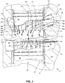
- FIGS. 1-3 shows a portion of a ported uniflow engine 21 with a fluid flow arrangement according to an aspect of the present invention.
- the uniflow engine 21 can comprise an engine block 23 or other structure in which a cylinder 25 (i.e., at least one) having a cylinder wall 27 is provided.
- the cylinder 25 is ordinarily circularly cylindrical, but may have other shapes.
- FIGS. 1-3 show an opposed piston engine 21, however, it will be appreciated that the invention is applicable to a single piston engine 21' as seen in FIG. 4 .
- the opposed piston engine 21 is shown with the cylinder oriented such that the intake is at the top and the exhaust is at the bottom, while the single piston engine 21' is shown with cylinder oriented such that the intake is at the bottom and the exhaust is at the top, however, in either case, the orientation of the intake and exhaust at the top or the bottom may be reversed.
- structures of the opposed piston engine 21 will be described, however, it will be appreciated that such structures are also applicable to the single piston engine 21', except where otherwise indicated.
- An inlet channel 29 is provided, usually formed in the engine block, into which intake air (or air and fuel, or other gas - hereinafter generically referred to as "air") is drawn and directed toward the cylinder 25.
- the inlet channel 29 may comprise plural channels.
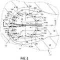
- An extension of a central axis AI of the inlet channel 29 first (in a direction of air flow) intersects the cylinder wall 27 in a first portion 31 ( FIGS. 1-2 ) of the cylinder 25 and next in a second portion 33 of the cylinder opposite the first portion of the cylinder.
- the first and second portions 31 and 33 may be but are not necessarily first and second halves of the cylinder 25.
- the central axis Al of the inlet channel 29 can define an acute angle greater than 0° with a longitudinal axis AC of the cylinder 25 to facilitate providing an axial component to the motion of the air entering the cylinder.
- An intake air gallery 35 ordinarily extends around at least a majority of a circumference of the cylinder 25, however, the intake air gallery may comprise two or more galleries that may (or may not be) be separated by a wall.
- the intake air gallery 35 has a gallery wall 37 and is in flow communication with the inlet channel 29. If plural channels 29 are provided, they may be arranged to be in flow communication with respective galleries 35 or portions of a single gallery at different portions around the circumference of the cylinder.
- a plurality of intake ports 39a...39h extend between the cylinder wall 27 and the gallery wall 37.
- the intake ports 39a...39h can be formed in a cylinder liner 41, an interior of which forms the cylinder 25. While FIG. 2 shows fifteen intake ports, it will be appreciated that any number of intake ports can be provided.
- At least some of the intake ports 39a and 39b have different areas at the cylinder wall 27 measured perpendicular to longitudinal axes A39a and A39b of the intake ports.
- An area of at least one intake port 39a in the first portion 31 of the cylinder 25 is larger than an area of at least one intake port 39b in the second portion 33 of the cylinder. More precisely, the area of at least one intake port 39a disposed in the first portion 31 of the cylinder 25 is larger than the area of another intake port 39b located substantially diametrically opposite the intake port 39a.
- the location and dimensions of the intake ports 39a ... 39h is ordinarily designed to facilitate directing an intake air charge so that it enters the cylinder 25 in a way that achieves minimum turbulence (and, thus, causing less heat transfer to the walls of the cylinder, requiring less work to induce charge motion, and resulting in less mixing of fresh and burned gases) while evenly filling the cylinder across its diameter, and thus facilitating the creation of (as close as possible to) a generally cylindrical volume that expands along the axis AC of the cylinder 25 to push out the spent gases with a minimum of mixing or energy exchange.
- Ports on the back side of the cylinder 25, e.g., port 39b, relative to the central axis Al of the inlet channel 29, i.e., the second portion 33 of the cylinder, are ordinarily smaller than ports on the front side of the cylinder, e.g., port 39a, relative to the central axis of the inlet channel, i.e., the first portion 31 of the cylinder, and are ordinarily fed from a portion of the intake air gallery 35 that has a reduced cross-section relative to portions of the intake air gallery closer to the ports on the from side of the cylinder.
- the ports on the back side or second portion 33 of the cylinder 25 are ordinarily primarily intended to cool the back side of a piston 43 in the cylinder and to create a small air curtain near the cylinder wall to facilitate completely filling the cylinder.
- the piston 43 can also be shaped to facilitate creation of the generally cylindrical volume by sloping a face 45 of the piston so that a mean face 47 of the piston defines a non-zero angle with a plane perpendicular to a longitudinal axis AC of the cylinder 25.
- the lowest part 49 of the mean face 47 of the piston 43 i.e., the part furthest from what shall be referred to as a position of minimum volume in the cylinder 51 (i.e., the part that extends the least into the cylinder), is adjacent the first portion 31 of the cylinder.
- the position of minimum volume in the cylinder 51 is defined as the point in the cylinder 25, in a single piston arrangement ( FIG. 4 ), at which the piston is at top dead center or, in an opposed piston arrangement ( FIG.
- a highest part 53 of the mean face 47 of the piston 43 closest to the position of minimum volume in the cylinder 51 is adjacent the second portion 33 of the cylinder 25.
- the total area of the intake ports 39a...39h is chosen to achieve the desired flow rate at a desired pressure change across the uniflow engine.
- the size of the walls (i.e., thickness between the cylinder wall 27 and the intake air gallery wall 37 and circumferential length of walls) separating the intake ports 39a...39h is sufficient to provide an acceptable level of mechanical strength for the intended operating conditions in the cylinder,
- the spacing of the intake ports 39a...39h and, thus, the width of the intake ports is ordinarily chosen so that piston rings 55 ( FIG. 1 ) on the piston 43 in the cylinder 25 do not expand into the ports or catch on the end walls (top and bottom portions) of the ports when the piston passes back and forth across the intake ports.
- the length and position of the intake ports along the cylinder axis AC are selected to function together with the piston, which acts as a valve, to achieve a desired opening and closing profile, and to obtain a desired effective compression ratio of the cylinder.
- the intake ports 39a and 39b are not exactly diametrically opposed from each other, however, the port 39b is disposed at about 170°-190° on the opposite side of the diameter of the cylinder 25 to the port 39a.
- the intake air gallery 37 does not extend completely around the circumference of the cylinder 25 but, rather, only around a majority of the circumference, with two ports 39b defining ends of the gallery. If the intake air gallery were formed so that it extended around an entire circumference of the cylinder, the port of minimum area could be disposed diametrically opposite the port of greatest area.
- Areas of intake ports decrease in area from a maximum area of at least one intake port 39a closest to a center of the first portion 31 of the cylinder 25 to a minimum area of at least one other intake port 39b located substantially diametrically opposite the intake port 39a. While there are not necessarily intake ports between the ports 39a and 39b, there is ordinarily at least one intake port 39c, 39d, 39e, 39f, 39g, 39h between the intake port 39a and the intake port 39b.
- the intake ports 39a...39h can be arranged symmetrically around the circumference of the cylinder 25.
- the intake ports 39a ... 39h can be but are not necessarily spaced at equal angles around the circumference.
- 39h can have areas that are the same as one or the other of the ports 39a or 39b, but ordinarily have an area or areas between the maximum area and the minimum area, with the areas ordinarily progressively decreasing in size from largest closest to the intake port 39a to smallest closest to the intake port 39b.
- Longitudinal axes A39a and A39b of at least some of the intake ports 39a...39h can be substantially coincident with radii Ra, Rb ( FIG. 2 ) of the cylinder 25 that intersect respective ones of the at least some of the intake ports.
- Longitudinal axes A39a...A39h of at least some, ordinarily most or all, of the intake ports 39a...39h are substantially parallel, i.e., forming an angle of about 10° or less, to the central axis A1 of the inlet channel 37.
- the intake ports 39a...39h are ordinarily longer in a direction parallel to a longitudinal axis AC of the cylinder 25 than in a direction of the circumference of the cylinder and are generally in the shape of elongated slots, Where the first portion 31 of the cylinder 25 is a first half of the cylinder or front of the cylinder closest to the inlet channel 29, and the second portion 33 the cylinder is a second half of the cylinder on a back side of the cylinder relative to the inlet channel, a greater number of the plurality of intake ports 39b, 39b, 39f, 39f, 39g, 39g 39h, 39h may be disposed in the second half of the cylinder than the number of intake ports 39a, 39c, 39c, 39d, 39d, 39e, 39e in the first half the cylinder while, at the same time, a total area of all intake ports in the first half of the cylinder combined may be greater than a total area of all intake ports in the second half of the cylinder combined.
- the intake port dimensions are ordinarily proportional to the volume of the slice of the cylinder to which it corresponds and, thus, the intake port 39a most closely directed toward the axis AC of the cylinder (and, thus, the widest portion of the cylinder in cross-section) is ordinarily larger than the others. It will be appreciated that, in reality, the air streams entering the cylinder 25 through the various intake ports 39a ...
- intake ports farthest away from the center axis e.g., intake ports 39b, 39b, 39f, 39f, 39g, 39g 39h, 39h, and proceeding around the back side of the cylinder may be angled or specially shaped, and in particular shaped to direct the air along the inside wall of the cylinder, to "fill in" relatively dead areas to complete the axial-moving charge air surface. While covering somewhat more than 180° of cylinder liner, these intake ports will ordinarily only supply a relatively small amount of the total charge air.
- a cross-sectional area of the intake air gallery 35 can decrease from a largest gallery area closest to the first portion 31 of the cylinder 25 to a smallest gallery area closest to the second portion of the cylinder 33.
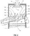
- a portion 37p of the gallery wall 37 closest to the position of minimum volume in the cylinder 51 can define an acute angle greater than 0° with the longitudinal axis AC of the cylinder to facilitate providing a desired direction of air flow into the cylinder 25.
- the intake air gallery 35 supplying air to the cylinder 25 does not, in general, direct the air flow toward the cylinder axis. To the extent that this occurs, it is primarily a consequence of the orientation of the intake ports and interaction of air flow from the intake ports with the face 45 of the piston 43.
- the primary purpose of the intake air gallery 35 is to supply a smooth, relatively non-turbulent flow of air in sufficient volume to minimize a pressure drop during scavenging so that the ports 39a ... 39h and piston face 45 can direct the air appropriately.
- the portion 37p of the gallery wall 37 may, however, have sloping or rounded transitions into the intake air ports 39a...39h to better utilize the length of the intake air ports between the gallery wall 37 and the cylinder wall 27 add to an axial component to air motion before it enters the cylinder. This effect may be the same for all ports or may vary to achieve the desired flow motion.
- the engine 21 can further comprise an outlet channel 57, particularly in an opposed piston engine, an exhaust air gallery 59 extending around at least a majority of a circumference of the cylinder 25, the exhaust air gallery having an exhaust air gallery wall 61 and being in flow communication with the outlet channel, and a plurality of exhaust ports 63 extending between the cylinder wall 27 and the exhaust air gallery wall.
- the exhaust ports 63 of the plurality of exhaust ports can be spaced at equal angles around the circumference of the cylinder 25 and can be of equal size, which can facilitate even removal of spent gases as they are forced toward the exhaust ports by the volume of incoming air.
- the piston 43 is an intake piston, and the uniftow engine comprises an exhaust piston 65 disposed in the cylinder.
- the two pistons 43 and 65 are disposed in the cylinder 25 to close the ends of the cylinder and define a chamber.
- the piston 43 or pistons 43 and 65 are typically not flat surfaces but, instead, are sculpted in order to create a cavity that is more favorable for combustion.
- the two pistons 43 and 65 will ultimately come together in near proximity to each other at the point of minimum volume of the cylinder 51 near the center of the cylinder.
- the cavities sculpted in the pistons 43 and 65 together form a desired combustion chamber.
- a single piston engine 21' FIG.
- combustion occurs between the piston face 45' and a cylinder head 77'.
- Angling the nominal separating plane or mean face 47 between pistons 43 and 65 or the mean piston face 47' (and possibly the cylinder head 65') can facilitate redirecting the now of the incoming charge from a radial to an axial direction.
- At least one fuel injector 67 can be provided for injecting fuel into the cylinder 25.
- a portion of the exhaust piston 63 closest to the at least one fuel injector 67 can include a recess 69 (shown in phantom) to facilitate introducing fuel injected by the fuel injector or, as seen in FIG. 3 , to receive a portion 71 (shown in phantom) of the fuel injector 67 that extends into the cylinder when the exhaust piston is at the position of minimum volume of the exhaust, piston.
- diesel engine combustion chambers were characterized as “quiescent” or "high swirl".
- a quiescent chamber air is introduced with as little turbulence as possible, and mixing is accomplished by extremely high fuel injection pressure sprays.
- swirl chambers the intake air is intentionally caused to swirl in the chamber by offsetting the intake ports to the cylinder, and by shaping the port runner walls to induce swirl into the air before it enters the cylinder. This allows air-fuel mixing with lower injection pressures.
- the combustion chambers according to the present invention might be characterized as "semi-quiescent".
- the combination of the geometries such as those of the inlet channel 29, the intake air gallery 35, the intake ports 39a...39g, the pistons 43 and 65, and the exhaust ports 63 can facilitate filling the cylinder 25 with intake air through the intake ports 39a...39g that are arranged in the wall 27 of the cylinder while pushing another gas (in the case of an internal combustion engine, the exhaust, or "spent", or burned combustion gases, from the previous cycle) out of exhaust ports 63 in the cylinder.
- the design goal is to provide as much fresh intake air as possible in the cylinder, which implies also removing as much of the binned gas as possible at the same time.
- the maximum replacement of the burned gas with fresh air occurs when the two can be prevented from mixing.
- the combination of the geometries of the inlet channel 29, the intake air gallery 35, the intake ports 39a...39g, and the piston 43 facilitates introducing the fresh intake gas into the cylinder 25 in such a way as to create a create a plug of fresh gas, with a predominantly flat, non-turbulent boundary between it and the burned gas in the cylinder 25, that then expands evenly from one end of the cylinder, and displaces the burned gas evenly along the axis AC of the cylinder.
- the conditions that make this distinct boundary possible include: 1) the pressure in the plug of intake gas being essentially constant across the entire cross sectional area of the cylinder, from edge to center; 2) the velocity vectors of the intake gas entering through the various intake ports 39a...39g being essentially parallel to each other, and normal to the boundary surface; and 3) there being little or no turbulent velocity components across the boundary surface.
- the reduced turbulence can minimize heat transfer between the incoming air and the cylinder walls, thus increasing thermal efficiency, reduce mixing between the intake and combusted gases, resulting in higher purity of charge, and more closely resembling what is considered "perfect displacement" scavenging for higher power density.
- the charge motion needed for complete combustion can be achieved with injection spray without the need for inducing swirl for mixing of fuel and intake air.
- the exhaust exits through the exhaust ports 63 which are also in the wall 27 of the cylinder 25, but at an opposite end of the cylinder from the intake air ports 39a...39h.
- the exhaust gas could also exit through poppet valves or any other type of valves that might be placed in a cylinder head or other location in or near the end of the cylinder opposite the intake air ports 39a ... 39h, depending on the engine configuration.
- the angled mean face 47 of the piston 43 can be beneficial because, if the intake air were to be introduced evenly around the entire circumference of the cylinder 25, the streams of gas from opposite sides of the cylinder would tend to collide at the center and create a tumbling, turbulent motion that would then cause mixing of gases, reducing the effectiveness of the scavenging process somewhat.
- the angled mean face 45 of the piston 43 can serve to: 1) turn the direction of the incoming air flow from a generally radial direction toward a direction along the axis AC of the cylinder 25, normal to the desired boundary surface between the incoming air and the gases sought to be exhausted; 2) forms a wedge of incoming gas to build an even pressure plug across the majority of the cylinder cross section; and 3) helps direct the gas flows that are away from the primary intake How to also turn parallel to the cylinder axis, to fill in the fresh gas plug all the way to the edges of the cylinder.
- the structure described above with respect to the opposed piston uniflow engine 21 can be applicable to a single piston uniflow engine 21' as seen in FIG. 4 .
- the single piston uniflow engine 21' can include one or more valves 73' for opening and closing an opening 75' in the cylinder head 77'.
- a single poppet type valve is shown for purposes of illustration, however, it will be appreciated that plural and/or other types of valves may be used.
- the single piston uniflow engine 21' can have structures corresponding to those of the opposed piston uniflow engine 21, such as a cylinder 25', an inlet channel 29', an intake air gallery 35', intake ports 39a ... 39h, and a piston 43' with a mean face 47' disposed at a non-zero angle to a perpendicular of the axis AC of the cylinder 25'.
Landscapes
- Engineering & Computer Science (AREA)
- Chemical & Material Sciences (AREA)
- Combustion & Propulsion (AREA)
- Mechanical Engineering (AREA)
- General Engineering & Computer Science (AREA)
- Cylinder Crankcases Of Internal Combustion Engines (AREA)
Claims (18)
- Gleichlaufmotor, umfassend:einen Zylinder mit einer Zylinderwand;einen Einlasskanal, wobei eine Verlängerung einer Mittelachse des Einlasskanals die Zylinderwand zuerst in einem ersten Abschnitt des Zylinders schneidet und danach die Zylinderwand in einem dem ersten Abschnitt des Zylinders gegenüberliegenden zweiten Abschnitt des Zylinders schneidet;einen Ansaugluftkorridor, wobei der Ansaugluftkorridor eine Korridorwand aufweist und in strömender Verbindung mit dem Einlasskanal ist; undeine Vielzahl von Ansaugkanälen, die sich zwischen der Zylinderwand und der Korridorwand erstrecken, wobei wenigstens einige der Ansaugkanäle an der Zylinderwand unterschiedliche Bereiche aufweisen, die senkrecht zu Längsachsen der Ansaugkanäle gemessen werden, und wobei ein Bereich wenigstens eines Ansaugkanals in dem ersten Abschnitt des Zylinders größer als ein Bereich wenigstens eines Ansaugkanals in dem zweiten Abschnitt des Zylinders ist, und wobei Längsachsen einer Mehrzahl der Ansaugkanäle bezüglich einer Mittelachse des Einlasskanals einen Winkel von 10° oder weniger bilden,dadurch gekennzeichnet, dassder Bereich wenigstens eines Ansaugkanals, der im ersten Abschnitt des Zylinders angeordnet ist, größer als der Bereich eines anderen Ansaugkanals ist, der im Wesentlichen diametral gegenüber dem wenigstens einen Ansaugkanal, der in dem ersten Abschnitt des Zylinders angeordnet ist, platziert ist.
- Gleichlaufmotor nach Anspruch 1, wobei Bereiche von Ansaugkanälen in dem Bereich von einem maximalen Bereich wenigstens eines Ansaugkanals, der am nächsten zu einem Zentrum des ersten Abschnitts des Zylinders ist, zu einem minimalen Bereich wenigstens eines anderen Ansaugkanals hin abnimmt, der im Wesentlichen diametral gegenüber dem wenigstens einen Ansaugkanal platziert ist, der am nächsten zum Zentrum des ersten Abschnitts des Zylinders ist.
- Gleichlaufmotor nach Anspruch 1, wobei Längsachsen wenigstens einiger der Ansaugkanäle im Wesentlichen mit Radien des Zylinders zusammenfallen, die jeweilige der wenigstens einigen der Ansaugkanäle schneiden.
- Gleichlaufmotor nach Anspruch 1, wobei die Ansaugkanäle in einer Richtung parallel zu einer Längsachse des Zylinders größer sind als in einer Umfangsrichtung des Zylinders.
- Gleichlaufmotor nach Anspruch 1, wobei der erste Abschnitt des Zylinders eine erste Hälfte des Zylinders und der zweite Abschnitt des Zylinders eine zweite Hälfte des Zylinders ist, und eine größere Anzahl der Vielzahl von Ansaugkanälen in der zweiten Hälfte des Zylinders als in der ersten Hälfte des Zylinders angeordnet ist.
- Gleichlaufmotor nach Anspruch 5, wobei ein Gesamtbereich aller Ansaugkanäle in der ersten Hälfte des Zylinders in Kombination größer als ein Gesamtbereich aller Ansaugkanäle in der zweiten Hälfte des Zylinders in Kombination ist.
- Gleichlaufmotor nach Anspruch 1, wobei ein Querschnittsbereich des Korridors von einem größten Korridorbereich am nächsten zu dem ersten Abschnitt des Zylinders hin zu einer kleinsten Korridorbereich am nächsten zu dem zweiten Abschnitt des Zylinders abnimmt.
- Gleichlaufmotor nach Anspruch 1, wobei ein Abschnitt der Korridorwand am nächsten zu einer Position eines minimalen Volumens im Zylinder einen spitzen Winkel von größer als 0° mit einer Längsachse des Zylinders definiert.
- Gleichlaufmotor nach Anspruch 1, wobei die Mittelachse des Einlasskanals einen spitzen Winkel größer als 0° mit einer Längsachse des Zylinders definiert.
- Gleichlaufmotor nach Anspruch 1, ferner umfassend einen Auslasskanal, einen Abluftkorridor, der sich wenigstens größtenteils um einen Umfang des Zylinders erstreckt, wobei der Abluftkorridor eine Abluftkorridorwand aufweist und in strömender Verbindung mit dem Auslasskanal ist, und eine Vielzahl von Abluftkanälen sich zwischen der Zylinderwand und der Abluftkorridorwand erstreckt.
- Gleichlaufmotor nach Anspruch 10, wobei Abluftkanäle der Vielzahl von Abluftkanälen in Umfangsrichtung des Zylinders in gleichen Winkeln verteilt sind.
- Gleichlaufmotor nach Anspruch 10, wobei alle Abluftkanäle der Vielzahl von Abluftkanälen von gleicher Größe sind.
- Gleichlaufmotor nach Anspruch 1, umfassend einen Kolben, der in dem Zylinder angeordnet ist, wobei eine mittlere Fläche des Kolbens einen Winkel von ungleich Null mit einer Ebene bildet, die senkrecht zu einer Längsachse des Zylinders ist.
- Gleichlaufmotor nach Anspruch 13, wobei ein unterster Teil der mittleren Fläche des Kolbens, der am weitesten von einer Position eines minimalen Volumens in dem Zylinder entfernt ist, angrenzend an den ersten Abschnitt des Zylinders ist, und wobei ein höchster Teil der mittleren Fläche des Kolbens, der am nächsten zu der Position eines minimalen Volumens in dem Zylinder ist, angrenzend an den zweiten Abschnitt des Zylinders ist.
- Gleichlaufmotor nach Anspruch 13, wobei der Gleichlaufmotor ein Gegenkolbenmotor ist, der Kolben ein Ansaugkolben ist, der Gleichlaufmotor einen Abgaskolben umfasst, der in dem Zylinder angeordnet ist.
- Gleichlaufmotor nach Anspruch 15, umfassend wenigstens eine Kraftstoffeinspritzung zum Einspritzen von Kraftstoff in den Zylinder, wobei ein Abschnitt des Abgaskolbens am nächsten zu der wenigstens einen Kraftstoffeinspritzung eine Aussparung umfasst.
- Gleichlaufmotor nach Anspruch 16, wobei wenigstens ein Abschnitt der wenigstens einen Kraftstoffeinspritzung sich in den Zylinder erstreckt, wobei der Abschnitt der wenigstens einen Kraftstoffeinspritzung in der Aussparung angeordnet ist, wenn der Abgaskolben sich in einer Position eines minimalen Volumens des Abgaskolbens befindet.
- Gleichlaufmotor nach Anspruch 1, wobei der Einlasskorridor sich wenigstens über einen Großteil eines Umfangs des Zylinders erstreckt.
Applications Claiming Priority (1)
| Application Number | Priority Date | Filing Date | Title |
|---|---|---|---|
| PCT/US2014/058103 WO2016053253A1 (en) | 2014-09-29 | 2014-09-29 | Uniflow engine with fluid flow arrangement |
Publications (3)
| Publication Number | Publication Date |
|---|---|
| EP3201448A1 EP3201448A1 (de) | 2017-08-09 |
| EP3201448A4 EP3201448A4 (de) | 2018-02-28 |
| EP3201448B1 true EP3201448B1 (de) | 2018-11-14 |
Family
ID=55631110
Family Applications (1)
| Application Number | Title | Priority Date | Filing Date |
|---|---|---|---|
| EP14903442.3A Active EP3201448B1 (de) | 2014-09-29 | 2014-09-29 | Gleichlaufmotor mit anordnung zur fluidströmung |
Country Status (4)
| Country | Link |
|---|---|
| US (1) | US10309295B2 (de) |
| EP (1) | EP3201448B1 (de) |
| CN (1) | CN107076009B (de) |
| WO (1) | WO2016053253A1 (de) |
Families Citing this family (3)
| Publication number | Priority date | Publication date | Assignee | Title |
|---|---|---|---|---|
| US11085297B1 (en) * | 2016-02-24 | 2021-08-10 | Enginuity Power Systems, Inc | Opposed piston engine and elements thereof |
| US10724467B2 (en) | 2016-11-04 | 2020-07-28 | Cummins Inc. | Pistons with thermal barrier coatings |
| US10731259B2 (en) | 2016-11-04 | 2020-08-04 | Cummins Inc. | Pistons with thermal barrier coatings |
Family Cites Families (17)
| Publication number | Priority date | Publication date | Assignee | Title |
|---|---|---|---|---|
| GB589988A (de) | ||||
| US1623704A (en) * | 1921-09-17 | 1927-04-05 | Super Diesel Tractor Corp | Apparatus for and method of creating turbulence |
| US2204296A (en) * | 1938-01-06 | 1940-06-11 | Petters Ltd | Scavenging of the cylinders of twostroke internal combustion engines |
| US2646779A (en) * | 1951-11-10 | 1953-07-28 | Harlan N Fiser | Sleeve valve means for two-cycle reciprocating engines |
| US2744506A (en) * | 1953-05-19 | 1956-05-08 | Texaco Development Corp | Two-stroke uniflow-scavenged internal combustion engine |
| US2853983A (en) * | 1956-06-08 | 1958-09-30 | Jr William S Sawle | Internal combustion engine of opposed piston type |
| GB885281A (en) | 1958-06-12 | 1961-12-20 | William Stephen Sawle | Internal combustion engine of opposed piston type |
| US3059626A (en) * | 1960-03-15 | 1962-10-23 | Nordberg Manufacturing Co | Two-cycle scavenging system |
| US3425399A (en) | 1966-05-23 | 1969-02-04 | American Gas Ass | Stratified charge gas engine |
| US3492979A (en) * | 1968-02-06 | 1970-02-03 | Boris M Osojnak | Internal combustion engine |
| US3799130A (en) | 1971-06-21 | 1974-03-26 | K Dahlstrom | Internal combustion engine |
| JPS5546012A (en) * | 1978-09-25 | 1980-03-31 | Toyota Motor Corp | Two cycle gasoline engine |
| US6382176B1 (en) * | 2000-06-07 | 2002-05-07 | Design & Manufacturing Solutions, Inc. | Method for injecting and combusting fuel with a piston head having a top surface recess |
| US8051830B2 (en) * | 2009-08-04 | 2011-11-08 | Taylor Jack R | Two-stroke uniflow turbo-compound internal combustion engine |
| US8677749B2 (en) | 2011-01-28 | 2014-03-25 | EcoMotors International | Exhaust system for an internal combustion engine |
| GB2493260A (en) * | 2011-07-26 | 2013-01-30 | Ecomotors Internat Inc | Opposed piston engine with tumble flow in shaped combustion chamber |
| JP2014098346A (ja) * | 2012-11-14 | 2014-05-29 | Mitsubishi Heavy Ind Ltd | ユニフロー式ディーゼル機関 |
-
2014
- 2014-09-29 EP EP14903442.3A patent/EP3201448B1/de active Active
- 2014-09-29 CN CN201480082316.8A patent/CN107076009B/zh active Active
- 2014-09-29 WO PCT/US2014/058103 patent/WO2016053253A1/en not_active Ceased
- 2014-09-29 US US15/512,558 patent/US10309295B2/en active Active
Non-Patent Citations (1)
| Title |
|---|
| None * |
Also Published As
| Publication number | Publication date |
|---|---|
| CN107076009A (zh) | 2017-08-18 |
| US10309295B2 (en) | 2019-06-04 |
| CN107076009B (zh) | 2019-08-13 |
| US20170335752A1 (en) | 2017-11-23 |
| EP3201448A1 (de) | 2017-08-09 |
| EP3201448A4 (de) | 2018-02-28 |
| WO2016053253A1 (en) | 2016-04-07 |
Similar Documents
| Publication | Publication Date | Title |
|---|---|---|
| US10968742B2 (en) | Engine with work stroke and gas exchange through piston rod | |
| KR102801178B1 (ko) | 예연소실 | |
| EP3201448B1 (de) | Gleichlaufmotor mit anordnung zur fluidströmung | |
| CN113646507B (zh) | 活塞杆和自由活塞发动机 | |
| US20030111026A1 (en) | Internal combustion engine | |
| US11686199B2 (en) | Engine with gas exchange through piston rod | |
| US11008864B2 (en) | Engine with work stroke and gas exchange through piston rod | |
| HK1255025B (en) | Free piston engine | |
| HK40061278A (en) | Piston rod and free piston engine | |
| JP2019074013A (ja) | 内燃機関のピストン |
Legal Events
| Date | Code | Title | Description |
|---|---|---|---|
| STAA | Information on the status of an ep patent application or granted ep patent |
Free format text: STATUS: THE INTERNATIONAL PUBLICATION HAS BEEN MADE |
|
| PUAI | Public reference made under article 153(3) epc to a published international application that has entered the european phase |
Free format text: ORIGINAL CODE: 0009012 |
|
| STAA | Information on the status of an ep patent application or granted ep patent |
Free format text: STATUS: REQUEST FOR EXAMINATION WAS MADE |
|
| 17P | Request for examination filed |
Effective date: 20170331 |
|
| AK | Designated contracting states |
Kind code of ref document: A1 Designated state(s): AL AT BE BG CH CY CZ DE DK EE ES FI FR GB GR HR HU IE IS IT LI LT LU LV MC MK MT NL NO PL PT RO RS SE SI SK SM TR |
|
| AX | Request for extension of the european patent |
Extension state: BA ME |
|
| DAX | Request for extension of the european patent (deleted) | ||
| A4 | Supplementary search report drawn up and despatched |
Effective date: 20180131 |
|
| RIC1 | Information provided on ipc code assigned before grant |
Ipc: F02B 25/04 20060101AFI20180125BHEP Ipc: F02F 1/22 20060101ALI20180125BHEP Ipc: F02B 25/08 20060101ALI20180125BHEP Ipc: F02B 75/28 20060101ALI20180125BHEP |
|
| REG | Reference to a national code |
Ref country code: DE Ref legal event code: R079 Ref document number: 602014036292 Country of ref document: DE Free format text: PREVIOUS MAIN CLASS: F02B0029000000 Ipc: F02B0025040000 |
|
| GRAP | Despatch of communication of intention to grant a patent |
Free format text: ORIGINAL CODE: EPIDOSNIGR1 |
|
| STAA | Information on the status of an ep patent application or granted ep patent |
Free format text: STATUS: GRANT OF PATENT IS INTENDED |
|
| RIC1 | Information provided on ipc code assigned before grant |
Ipc: F02B 25/08 20060101ALI20180531BHEP Ipc: F02B 25/04 20060101AFI20180531BHEP Ipc: F02B 75/28 20060101ALI20180531BHEP Ipc: F02F 1/22 20060101ALI20180531BHEP |
|
| INTG | Intention to grant announced |
Effective date: 20180702 |
|
| GRAS | Grant fee paid |
Free format text: ORIGINAL CODE: EPIDOSNIGR3 |
|
| GRAA | (expected) grant |
Free format text: ORIGINAL CODE: 0009210 |
|
| STAA | Information on the status of an ep patent application or granted ep patent |
Free format text: STATUS: THE PATENT HAS BEEN GRANTED |
|
| AK | Designated contracting states |
Kind code of ref document: B1 Designated state(s): AL AT BE BG CH CY CZ DE DK EE ES FI FR GB GR HR HU IE IS IT LI LT LU LV MC MK MT NL NO PL PT RO RS SE SI SK SM TR |
|
| REG | Reference to a national code |
Ref country code: CH Ref legal event code: EP Ref country code: AT Ref legal event code: REF Ref document number: 1065092 Country of ref document: AT Kind code of ref document: T Effective date: 20181115 |
|
| REG | Reference to a national code |
Ref country code: DE Ref legal event code: R096 Ref document number: 602014036292 Country of ref document: DE |
|
| REG | Reference to a national code |
Ref country code: IE Ref legal event code: FG4D |
|
| REG | Reference to a national code |
Ref country code: NL Ref legal event code: MP Effective date: 20181114 |
|
| REG | Reference to a national code |
Ref country code: LT Ref legal event code: MG4D |
|
| REG | Reference to a national code |
Ref country code: SE Ref legal event code: TRGR |
|
| REG | Reference to a national code |
Ref country code: AT Ref legal event code: MK05 Ref document number: 1065092 Country of ref document: AT Kind code of ref document: T Effective date: 20181114 |
|
| PG25 | Lapsed in a contracting state [announced via postgrant information from national office to epo] |
Ref country code: LV Free format text: LAPSE BECAUSE OF FAILURE TO SUBMIT A TRANSLATION OF THE DESCRIPTION OR TO PAY THE FEE WITHIN THE PRESCRIBED TIME-LIMIT Effective date: 20181114 Ref country code: AT Free format text: LAPSE BECAUSE OF FAILURE TO SUBMIT A TRANSLATION OF THE DESCRIPTION OR TO PAY THE FEE WITHIN THE PRESCRIBED TIME-LIMIT Effective date: 20181114 Ref country code: NO Free format text: LAPSE BECAUSE OF FAILURE TO SUBMIT A TRANSLATION OF THE DESCRIPTION OR TO PAY THE FEE WITHIN THE PRESCRIBED TIME-LIMIT Effective date: 20190214 Ref country code: LT Free format text: LAPSE BECAUSE OF FAILURE TO SUBMIT A TRANSLATION OF THE DESCRIPTION OR TO PAY THE FEE WITHIN THE PRESCRIBED TIME-LIMIT Effective date: 20181114 Ref country code: HR Free format text: LAPSE BECAUSE OF FAILURE TO SUBMIT A TRANSLATION OF THE DESCRIPTION OR TO PAY THE FEE WITHIN THE PRESCRIBED TIME-LIMIT Effective date: 20181114 Ref country code: ES Free format text: LAPSE BECAUSE OF FAILURE TO SUBMIT A TRANSLATION OF THE DESCRIPTION OR TO PAY THE FEE WITHIN THE PRESCRIBED TIME-LIMIT Effective date: 20181114 Ref country code: BG Free format text: LAPSE BECAUSE OF FAILURE TO SUBMIT A TRANSLATION OF THE DESCRIPTION OR TO PAY THE FEE WITHIN THE PRESCRIBED TIME-LIMIT Effective date: 20190214 Ref country code: FI Free format text: LAPSE BECAUSE OF FAILURE TO SUBMIT A TRANSLATION OF THE DESCRIPTION OR TO PAY THE FEE WITHIN THE PRESCRIBED TIME-LIMIT Effective date: 20181114 Ref country code: IS Free format text: LAPSE BECAUSE OF FAILURE TO SUBMIT A TRANSLATION OF THE DESCRIPTION OR TO PAY THE FEE WITHIN THE PRESCRIBED TIME-LIMIT Effective date: 20190314 |
|
| PG25 | Lapsed in a contracting state [announced via postgrant information from national office to epo] |
Ref country code: GR Free format text: LAPSE BECAUSE OF FAILURE TO SUBMIT A TRANSLATION OF THE DESCRIPTION OR TO PAY THE FEE WITHIN THE PRESCRIBED TIME-LIMIT Effective date: 20190215 Ref country code: RS Free format text: LAPSE BECAUSE OF FAILURE TO SUBMIT A TRANSLATION OF THE DESCRIPTION OR TO PAY THE FEE WITHIN THE PRESCRIBED TIME-LIMIT Effective date: 20181114 Ref country code: PT Free format text: LAPSE BECAUSE OF FAILURE TO SUBMIT A TRANSLATION OF THE DESCRIPTION OR TO PAY THE FEE WITHIN THE PRESCRIBED TIME-LIMIT Effective date: 20190314 Ref country code: AL Free format text: LAPSE BECAUSE OF FAILURE TO SUBMIT A TRANSLATION OF THE DESCRIPTION OR TO PAY THE FEE WITHIN THE PRESCRIBED TIME-LIMIT Effective date: 20181114 Ref country code: NL Free format text: LAPSE BECAUSE OF FAILURE TO SUBMIT A TRANSLATION OF THE DESCRIPTION OR TO PAY THE FEE WITHIN THE PRESCRIBED TIME-LIMIT Effective date: 20181114 |
|
| PG25 | Lapsed in a contracting state [announced via postgrant information from national office to epo] |
Ref country code: DK Free format text: LAPSE BECAUSE OF FAILURE TO SUBMIT A TRANSLATION OF THE DESCRIPTION OR TO PAY THE FEE WITHIN THE PRESCRIBED TIME-LIMIT Effective date: 20181114 Ref country code: IT Free format text: LAPSE BECAUSE OF FAILURE TO SUBMIT A TRANSLATION OF THE DESCRIPTION OR TO PAY THE FEE WITHIN THE PRESCRIBED TIME-LIMIT Effective date: 20181114 Ref country code: CZ Free format text: LAPSE BECAUSE OF FAILURE TO SUBMIT A TRANSLATION OF THE DESCRIPTION OR TO PAY THE FEE WITHIN THE PRESCRIBED TIME-LIMIT Effective date: 20181114 Ref country code: PL Free format text: LAPSE BECAUSE OF FAILURE TO SUBMIT A TRANSLATION OF THE DESCRIPTION OR TO PAY THE FEE WITHIN THE PRESCRIBED TIME-LIMIT Effective date: 20181114 |
|
| REG | Reference to a national code |
Ref country code: DE Ref legal event code: R097 Ref document number: 602014036292 Country of ref document: DE |
|
| PG25 | Lapsed in a contracting state [announced via postgrant information from national office to epo] |
Ref country code: SK Free format text: LAPSE BECAUSE OF FAILURE TO SUBMIT A TRANSLATION OF THE DESCRIPTION OR TO PAY THE FEE WITHIN THE PRESCRIBED TIME-LIMIT Effective date: 20181114 Ref country code: RO Free format text: LAPSE BECAUSE OF FAILURE TO SUBMIT A TRANSLATION OF THE DESCRIPTION OR TO PAY THE FEE WITHIN THE PRESCRIBED TIME-LIMIT Effective date: 20181114 Ref country code: SM Free format text: LAPSE BECAUSE OF FAILURE TO SUBMIT A TRANSLATION OF THE DESCRIPTION OR TO PAY THE FEE WITHIN THE PRESCRIBED TIME-LIMIT Effective date: 20181114 Ref country code: EE Free format text: LAPSE BECAUSE OF FAILURE TO SUBMIT A TRANSLATION OF THE DESCRIPTION OR TO PAY THE FEE WITHIN THE PRESCRIBED TIME-LIMIT Effective date: 20181114 |
|
| PLBE | No opposition filed within time limit |
Free format text: ORIGINAL CODE: 0009261 |
|
| STAA | Information on the status of an ep patent application or granted ep patent |
Free format text: STATUS: NO OPPOSITION FILED WITHIN TIME LIMIT |
|
| 26N | No opposition filed |
Effective date: 20190815 |
|
| PG25 | Lapsed in a contracting state [announced via postgrant information from national office to epo] |
Ref country code: SI Free format text: LAPSE BECAUSE OF FAILURE TO SUBMIT A TRANSLATION OF THE DESCRIPTION OR TO PAY THE FEE WITHIN THE PRESCRIBED TIME-LIMIT Effective date: 20181114 |
|
| PG25 | Lapsed in a contracting state [announced via postgrant information from national office to epo] |
Ref country code: TR Free format text: LAPSE BECAUSE OF FAILURE TO SUBMIT A TRANSLATION OF THE DESCRIPTION OR TO PAY THE FEE WITHIN THE PRESCRIBED TIME-LIMIT Effective date: 20181114 |
|
| PG25 | Lapsed in a contracting state [announced via postgrant information from national office to epo] |
Ref country code: MC Free format text: LAPSE BECAUSE OF FAILURE TO SUBMIT A TRANSLATION OF THE DESCRIPTION OR TO PAY THE FEE WITHIN THE PRESCRIBED TIME-LIMIT Effective date: 20181114 |
|
| REG | Reference to a national code |
Ref country code: CH Ref legal event code: PL |
|
| PG25 | Lapsed in a contracting state [announced via postgrant information from national office to epo] |
Ref country code: LI Free format text: LAPSE BECAUSE OF NON-PAYMENT OF DUE FEES Effective date: 20190930 Ref country code: CH Free format text: LAPSE BECAUSE OF NON-PAYMENT OF DUE FEES Effective date: 20190930 Ref country code: LU Free format text: LAPSE BECAUSE OF NON-PAYMENT OF DUE FEES Effective date: 20190929 Ref country code: IE Free format text: LAPSE BECAUSE OF NON-PAYMENT OF DUE FEES Effective date: 20190929 |
|
| REG | Reference to a national code |
Ref country code: BE Ref legal event code: MM Effective date: 20190930 |
|
| PG25 | Lapsed in a contracting state [announced via postgrant information from national office to epo] |
Ref country code: BE Free format text: LAPSE BECAUSE OF NON-PAYMENT OF DUE FEES Effective date: 20190930 |
|
| GBPC | Gb: european patent ceased through non-payment of renewal fee |
Effective date: 20190929 |
|
| PG25 | Lapsed in a contracting state [announced via postgrant information from national office to epo] |
Ref country code: GB Free format text: LAPSE BECAUSE OF NON-PAYMENT OF DUE FEES Effective date: 20190929 |
|
| PG25 | Lapsed in a contracting state [announced via postgrant information from national office to epo] |
Ref country code: CY Free format text: LAPSE BECAUSE OF FAILURE TO SUBMIT A TRANSLATION OF THE DESCRIPTION OR TO PAY THE FEE WITHIN THE PRESCRIBED TIME-LIMIT Effective date: 20181114 |
|
| PG25 | Lapsed in a contracting state [announced via postgrant information from national office to epo] |
Ref country code: HU Free format text: LAPSE BECAUSE OF FAILURE TO SUBMIT A TRANSLATION OF THE DESCRIPTION OR TO PAY THE FEE WITHIN THE PRESCRIBED TIME-LIMIT; INVALID AB INITIO Effective date: 20140929 Ref country code: MT Free format text: LAPSE BECAUSE OF FAILURE TO SUBMIT A TRANSLATION OF THE DESCRIPTION OR TO PAY THE FEE WITHIN THE PRESCRIBED TIME-LIMIT Effective date: 20181114 |
|
| PG25 | Lapsed in a contracting state [announced via postgrant information from national office to epo] |
Ref country code: MK Free format text: LAPSE BECAUSE OF FAILURE TO SUBMIT A TRANSLATION OF THE DESCRIPTION OR TO PAY THE FEE WITHIN THE PRESCRIBED TIME-LIMIT Effective date: 20181114 |
|
| PGFP | Annual fee paid to national office [announced via postgrant information from national office to epo] |
Ref country code: DE Payment date: 20240926 Year of fee payment: 11 |
|
| PGFP | Annual fee paid to national office [announced via postgrant information from national office to epo] |
Ref country code: FR Payment date: 20240925 Year of fee payment: 11 |
|
| PGFP | Annual fee paid to national office [announced via postgrant information from national office to epo] |
Ref country code: SE Payment date: 20240925 Year of fee payment: 11 |