EP3201468B1 - Kühlkompressor und begrenzungsvorrichtung - Google Patents
Kühlkompressor und begrenzungsvorrichtung Download PDFInfo
- Publication number
- EP3201468B1 EP3201468B1 EP15847057.5A EP15847057A EP3201468B1 EP 3201468 B1 EP3201468 B1 EP 3201468B1 EP 15847057 A EP15847057 A EP 15847057A EP 3201468 B1 EP3201468 B1 EP 3201468B1
- Authority
- EP
- European Patent Office
- Prior art keywords
- lower housing
- pump body
- refrigeration compressor
- compressor
- limiting device
- Prior art date
- Legal status (The legal status is an assumption and is not a legal conclusion. Google has not performed a legal analysis and makes no representation as to the accuracy of the status listed.)
- Active
Links
Images

Classifications
-
- F—MECHANICAL ENGINEERING; LIGHTING; HEATING; WEAPONS; BLASTING
- F04—POSITIVE - DISPLACEMENT MACHINES FOR LIQUIDS; PUMPS FOR LIQUIDS OR ELASTIC FLUIDS
- F04B—POSITIVE-DISPLACEMENT MACHINES FOR LIQUIDS; PUMPS
- F04B53/00—Component parts, details or accessories not provided for in, or of interest apart from, groups F04B1/00 - F04B23/00 or F04B39/00 - F04B47/00
- F04B53/16—Casings; Cylinders; Cylinder liners or heads; Fluid connections
-
- F—MECHANICAL ENGINEERING; LIGHTING; HEATING; WEAPONS; BLASTING
- F04—POSITIVE - DISPLACEMENT MACHINES FOR LIQUIDS; PUMPS FOR LIQUIDS OR ELASTIC FLUIDS
- F04B—POSITIVE-DISPLACEMENT MACHINES FOR LIQUIDS; PUMPS
- F04B39/00—Component parts, details, or accessories, of pumps or pumping systems specially adapted for elastic fluids, not otherwise provided for in, or of interest apart from, groups F04B25/00 - F04B37/00
- F04B39/02—Lubrication
- F04B39/0223—Lubrication characterised by the compressor type
- F04B39/023—Hermetic compressors
-
- F—MECHANICAL ENGINEERING; LIGHTING; HEATING; WEAPONS; BLASTING
- F04—POSITIVE - DISPLACEMENT MACHINES FOR LIQUIDS; PUMPS FOR LIQUIDS OR ELASTIC FLUIDS
- F04B—POSITIVE-DISPLACEMENT MACHINES FOR LIQUIDS; PUMPS
- F04B39/00—Component parts, details, or accessories, of pumps or pumping systems specially adapted for elastic fluids, not otherwise provided for in, or of interest apart from, groups F04B25/00 - F04B37/00
- F04B39/12—Casings; Cylinders; Cylinder heads; Fluid connections
- F04B39/127—Mounting of a cylinder block in a casing
-
- F—MECHANICAL ENGINEERING; LIGHTING; HEATING; WEAPONS; BLASTING
- F04—POSITIVE - DISPLACEMENT MACHINES FOR LIQUIDS; PUMPS FOR LIQUIDS OR ELASTIC FLUIDS
- F04B—POSITIVE-DISPLACEMENT MACHINES FOR LIQUIDS; PUMPS
- F04B49/00—Control, e.g. of pump delivery, or pump pressure of, or safety measures for, machines, pumps, or pumping installations, not otherwise provided for, or of interest apart from, groups F04B1/00 - F04B47/00
- F04B49/10—Other safety measures
Definitions
- the invention relates to a refrigeration compressor, in particular to a sealed refrigeration compressor with a piston structure and a limiting device for the refrigeration compressor.
- Traditional sealed piston compressor is widely used for a refrigerator, a freezer comprising a compressor unit mounted in a sealed space formed by an upper housing and a lower housing, a motor and a bracket for fixing the compressor unit and the motor.
- a pump body the whole assembly of the compressor unit, the motor and the bracket is referred to a pump body.
- the pump is elastically supported by several supporting springs arranged at the bottom of the lower housing. This way of elastic support can avoid a direct collision between the pump body and the housing when the compressor works, thereby reducing vibration and noise.
- this traditional compressor is used in static environment, such as a household refrigerator, a freezer which has relatively steady working environment.
- the technical problem solved by the invention is to provide a refrigeration compressor and a limiting device for the refrigeration compressor, ensuring that the limiting device is smoothly mounted on an inner wall of a lower housing of the refrigeration compressor so as to prevent excessive inclination of the pump body caused by moving upward.
- the lower housing and the upper housing form an annular protrusion protruding towards the inner of the containing space at their joining portion; the protrusion is formed by a lower edge of the upper housing which is contained in the lower housing.
- the protrusion when the height of stator lamination is increased, the protrusion is located in a gap between the stepped portion and the lower housing.
- the limiting portion extends from a side portion of the stepped portion to a position above a portion of the pump body and forms a certain angle with the stepped portion.
- the height of the position, at which the mounting portion is attached to the inner wall of the lower housing is adjustable.
- the mounting portion is provided with at least one welding spot, the mounting portion is welded on the inner wall of the lower housing through at least one said welding spot.
- the pump body comprises a compressor assembly integrally assembled, a motor assembly for driving the compressor assembly, and an bracket for supporting the compressor assembly and the motor assembly, the motor assembly includes a rotor and a stator, the stator includes a stator lamination, wherein the limiting device of the pump body extends to above an upper surface of the stator lamination.
- the height of the stator lamination of the motor assembly varies with different requirements of the motor performance.
- two said limiting devices are symmetrically provided on the inner side wall of the lower housing.
- a limiting device for an refrigeration compressor comprising: a mounting portion for attaching the limiting device to an inner wall of the lower housing of the refrigeration compressor; a stepped portion connected to an upper end of the mounting portion and protruding towards one side relative to a surface of the mounting portion; and a limiting portion extending from a side portion of the stepped portion and inclined at an angle with respect to the stepped portion.
- the mounting portion is provided with at least one welding spot through which the limiting device is attached to the inner wall of the lower housing of the refrigeration compressor.
- the mounting portion, the stepped portion and the limiting portion of the limiting device are integral.
- the limiting device is provided with the stepped portion so that a space formed between the stepped portion and the lower housing may contain the protrusion formed at the joining portion of the upper housing and the lower housing, while keeping the mounting portion stably arranged on the inner wall of the lower housing.
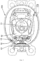
- a refrigeration compressor 100 according to an exemplary embodiment of the invention comprises: an upper housing 1, a lower housing 2, a guide post 3, a pump body and at least one limiting device 5.
- the upper housing 1 and the lower housing 2 are combined to form a containing space, and the upper housing 1 and the lower housing form an annular protrusion 11 protruding towards the containing space at a joining position.
- the pump body is arranged in the containing space and supported by the supporting spring.
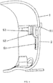
- the limiting device 5 is integrally formed by, for example, stainless steel sheet.
- the limiting device 5 comprises a mounting portion 51, a stepped portion 52 and a limiting portion 53.
- the mounting portion 51 is mounted on an inner wall of the lower housing 2.
- the stepped portion 52 is connected to an upper end of the mounting portion 51, and the stepped portion 52 offsets away from a side of the lower housing 2 along an upper end of the mounting portion 51, so that a containing space is formed between the stepped portion 52 and the inner wall of the lower housing 2, when the limiting device 5 is mounted on the inner wall of the lower housing 2.
- the limiting portion 53 extends from the stepped portion 51 to a position above a stator 43 which is one of components of the pump body so as to block upward movement of the pump body.
- the pump body 4 comprises a compressor assembly 41 integrally assembled, a motor assembly for driving the compressor assembly 41, and a bracket for supporting the compressor assembly 41 and the motor assembly 42.
- the motor assembly includes a rotor 42 and a stator 43.
- the stator includes a stator lamination, wherein the limiting device 5 of the pump body extends to a position above an upper surface of the stator lamination.
- stator core laminations are formed by stacking simultaneously molded and punched metal sheets. A stator winding is fixed on the periphery of stator core laminations.
- the upper surface of the stator core laminations is a substantially flat surface, above which there is a space in sealed containing space.
- the protrusion 11 is formed by a lower edge of the upper housing 1 which is contained within an upper edge 21 of the lower housing 2.
- the upper housing 1 and the lower housing 2 are combined by, such as, welding, and the lower edge of the upper housing 1 protrudes inwardly inside the lower housing 2 to form an annular protrusion 11.
- the stepped portion 52 of the limiting device 5 is formed through inwardly, substantially perpendicular bent for two times relative to the mounting portion 51 so as to match with the shape of the protrusion 11.
- the limiting device 5 has a generally approximate inverted "L" shape in the plane view and is provided with the stepped portion 52 deviated relative to the surface of the mounting portion 51.
- the limiting portion 53 extends obliquely to a position above a portion 43 of the pump body from side portion of the stepped portion 52. In this way, as shown in FIG.
- a containing space formed between the stepped portion 52 and the inner wall of the lower housing 2 can be used for accommodating the protrusion 11 , thus, the length of the mounting portion 51 of the limiting device 5 may be changed such that it may still be installed on flat portion of the inner wall of the lower housing 2 in case that the height of the stator core laminations is substantially flush with the protrusion, at the same time, the limiting portion 53 can still be located above the stator laminations.
- the limiting device of the invention can be used to prevent excessive inclination of the pump body 4 caused by moving upward, which makes the detachment of the pump body from supporting spring, thus resulting in the failure of the compressor.
- a limited portion 43 of the pump body is a relatively static and substantially flat upper surface during operation of the compressor, and there is an appropriate space within the sealed space of the inner of the compressor above the upper surface, in which the limiting device 5 can be arranged to block upward movement of the pump body.
- a portion 43 limited by the limiting portion 53 may be an upper surface of the pump component, such as stator core laminations, because the stator core laminations have appropriate plane area and flatness.
- a portion limited by the limiting portion 53 also may be stator bracket, groove, hole and the like of the pump component.
- the limiting device 5 and a portion of the pump body are spaced apart with a predetermined gap in the up-down direction. Therefore, the limiting device 5 is arranged above upper surface of a portion 43 of the pump body and does not contact with each other. In this way, this will not produce friction during normal operation of the compressor, thereby there will not produce wear or noise. It should be noted that direct contact or pressing between the limiting device 5 and one portion of the pump body can also realize the restriction to upward movement of the pump body.
- the protrusion 11 is formed by the lower edge of the upper housing 1 which is contained in the lower housing 2, and the stepped portion 52 of the limiting device 5 is formed through inwardly, substantially perpendicular bent for two times relative to the mounting portion 51.
- the protrusion 11 is formed by an upper edge of the lower housing 2 which is contained in the upper housing, and the stepped portion of the limiting device is formed through outwardly, substantially perpendicular bent for two times relative to the mounting portion, such that there is a containing space between the stepped portion 53 and the lower housing 2 to contain an edge portion of the upper housing 1 installed on the lower housing 2.
- the mounting portion 51 is mounted on the inner wall of the lower housing 2 with the height being adjustable.
- the mounting portion 51 is provided with at least one welding spot 55.Thus, the mounting portion 51 can be installed at different height by selecting the welding spot 55 so as to adapt to different height of the stator core laminations, and to ensure that a containing space can be formed between the stepped portion 52 and the inner wall of the lower housing 2 to contain the protrusion 11.
- the motor assembly is replaceable, and the different stator core laminations of the motor assembly have different height.
- the stator core laminations with different height can be replaced so as to the motor assembly has different output power, correspondingly, changing the mounting height of the limiting device.
- two or more limiting device can be symmetrically arranged on the inner wall of the lower housing such that the pump 4 can be uniformly forced and not incline.
- a limiting device 5 for a refrigeration compressor 100 comprising: a mounting portion 51, a stepped portion 52 and a limiting portion 53.
- the mounting portion 51 is mounted on an inner wall of a lower housing 2 of the refrigeration compressor 100.
- the stepped portion 52 is connected to an upper end of the mounting portion 51 and protrudes towards one side relative to a surface of the mounting portion 51.
- the limiting portion extends obliquely from the side portion of the stepped portion 52.
- the mounting portion 51 is provided with at least one welding spot 55 to adjust mounting height of the limiting device 5.
- the limiting device 5 has a generally inverted "L" shape in the plane view, and the limiting portion 53 forms a stopper structure extending from side portion of the stepped portion 52.
- the stepped portion 52 is located in the direction away from the inner side wall of the lower housing 2, and the limiting portion 53 is located above a portion (such as stator core lamination) of the pump body, blocking the upward movement of the whole pump body.
- the stepped portion is arranged on the limiting device, such that a containing space can be formed between the stepped portion and the inner wall of the lower housing, therefore, the mounting portion is steadily mounted on the inner wall of the lower housing, and when the height of the pump increases (such as 5mm), due to the stepped portion, the limiting device will not hinder the installation of the upper housing on the lower housing.
- the pump moves upward, an upper surface of a portion of the pump will contact against the lower portion of the limiting portion of the limiting device, therefore the whole pump body cannot continue to move upward.
- this can prevent excessive inclination of the pump body caused by moving upward which makes the detachment of the pump body from supporting spring, resulting in the failure of the compressor.
- the height of the limiting device according to the embodiment of the invention is adjustable, therefore it can adapt to the stator core laminations with different height and allow the replacement of the motor assembly with different power, so that the refrigeration compressor has a different refrigerating capacity, and at the same time the volume of the entire housing does not need to be changed.
Landscapes
- Engineering & Computer Science (AREA)
- Mechanical Engineering (AREA)
- General Engineering & Computer Science (AREA)
- Compressor (AREA)
Claims (10)
- Kühlkompressor (100), umfassend:ein oberes Gehäuse (1) und ein unteres Gehäuse (2), die kombiniert sind, um einen Aufnahmeraum zu bilden;wenigstens einen Führungsstift (3), der im Inneren des unteren Gehäuses (2) angeordnet ist,eine Tragfeder, die auf den wenigstens einen Führungsstift (3) aufgesetzt ist;einen Pumpenkörper, der in dem Aufnahmeraum angeordnet ist und durch die Tragfeder getragen wird; undwenigstens eine Begrenzungsvorrichtung (5), umfassend:einen Montageabschnitt (51), der an einer Innenwand des unteren Gehäuses (2) montiert ist;einen abgestuften Abschnitt (52), der mit einem oberen Ende des Montageabschnitts (51) verbunden ist und in einer Richtung weg von der Innenwand des unteren Gehäuses (2) relativ zu einer Oberfläche des Montageabschnitts (51) vorspringt; wobei der Kühlkompressor (100) dadurch gekennzeichnet ist, dass die Begrenzungsvorrichtung (5) ferner einen Begrenzungsabschnitt (53) umfasst, der sich schräg von dem abgestuften Abschnitt (52) zu einer Position über einem Abschnitt (43) des Pumpenkörpers erstreckt, sodass die Aufwärtsbewegung des Pumpenkörpers blockiert wird.
- Kühlkompressor (100) nach Anspruch 1, dadurch gekennzeichnet, dass der Begrenzungsabschnitt (53) dafür eingerichtet ist, die Aufwärtsbewegung des Pumpenkörpers bei Kontakt eines unteren Abschnitts des Begrenzungsabschnitts (53) mit einer oberen Oberfläche des Abschnitts (43) des Pumpenkörpers zu blockieren.
- Kühlkompressor (100) nach Anspruch 1, dadurch gekennzeichnet, dass das untere Gehäuse (2) und das obere Gehäuse (1) an ihrem Verbindungsabschnitt einen ringförmigen Vorsprung (11) bilden, der zu dem Aufnahmeraum hin vorspringt;
wobei der ringförmige Vorsprung (11) durch eine untere Kante des oberen Gehäuses (1) gebildet wird, die in dem unteren Gehäuse (2) aufgenommen ist. - Kühlkompressor (100) nach Anspruch 3, dadurch gekennzeichnet, dass, wenn die Höhe einer Statorblechung zunimmt, sich der ringförmige Vorsprung (11) an einem Spalt zwischen dem abgestuften Abschnitt (52) und dem unteren Gehäuse (2) befindet.
- Kühlkompressor (100) nach Anspruch 1, dadurch gekennzeichnet, dass sich der Begrenzungsabschnitt (53) von einer Seite des abgestuften Abschnitts (52) zu der Position über dem Abschnitt (43) des Pumpenkörpers erstreckt und einen Winkel mit dem abgestuften Abschnitt (52) bildet.
- Kühlkompressor (100) nach einem der Ansprüche 1, 3, 4 oder 5, dadurch gekennzeichnet, dass der Montageabschnitt (51) mit wenigstens einem Schweißpunkt (55) versehen ist, der es ermöglicht, den Montageabschnitt (51) in unterschiedlicher Höhe einzubauen, indem der Schweißpunkt (55) ausgewählt wird.
- Kühlkompressor (100) nach Anspruch 6, dadurch gekennzeichnet, dass der Montageabschnitt (51) durch den wenigstens einen Schweißpunkt (55) an die Innenwand des unteren Gehäuses (2) geschweißt wird.
- Kühlkompressor (100) nach Anspruch 6, dadurch gekennzeichnet, dass der Pumpenkörper eine einstückig zusammengesetzte Kompressoranordnung (41), eine Motoranordnung zum Antreiben der Kompressoranordnung (41) und eine Halterung zum Tragen der Kompressoranordnung (41) und der Motoranordnung umfasst, die Motoranordnung einen Rotor (42) und einen Stator (43) umfasst und der Stator (43) eine Statorblechung umfasst, wobei sich die Begrenzungsvorrichtung (5) des Pumpenkörpers zu einer Position über einer oberen Oberfläche der Statorblechung erstreckt.
- Kühlkompressor (100) nach Anspruch 8, dadurch gekennzeichnet, dass die Höhe der Statorblechung der Motoranordnung mit den unterschiedlichen Anforderungen der Motorleistung variiert.
- Kühlkompressor (100) nach Anspruch 5, dadurch gekennzeichnet, dass zwei Begrenzungsvorrichtungen (5) symmetrisch an der Innenwand des unteren Gehäuses (2) vorgesehen sind.
Applications Claiming Priority (2)
| Application Number | Priority Date | Filing Date | Title |
|---|---|---|---|
| CN201420580968.1U CN204327448U (zh) | 2014-09-30 | 2014-09-30 | 制冷压缩机和限位装置 |
| PCT/CN2015/090720 WO2016050174A2 (en) | 2014-09-30 | 2015-09-25 | Refrigeration compressor and limiting device |
Publications (3)
| Publication Number | Publication Date |
|---|---|
| EP3201468A2 EP3201468A2 (de) | 2017-08-09 |
| EP3201468A4 EP3201468A4 (de) | 2018-05-23 |
| EP3201468B1 true EP3201468B1 (de) | 2020-08-26 |
Family
ID=53163817
Family Applications (1)
| Application Number | Title | Priority Date | Filing Date |
|---|---|---|---|
| EP15847057.5A Active EP3201468B1 (de) | 2014-09-30 | 2015-09-25 | Kühlkompressor und begrenzungsvorrichtung |
Country Status (3)
| Country | Link |
|---|---|
| EP (1) | EP3201468B1 (de) |
| CN (1) | CN204327448U (de) |
| WO (1) | WO2016050174A2 (de) |
Families Citing this family (5)
| Publication number | Priority date | Publication date | Assignee | Title |
|---|---|---|---|---|
| CN204327448U (zh) * | 2014-09-30 | 2015-05-13 | 思科普压缩机(天津)有限公司 | 制冷压缩机和限位装置 |
| CN111271260B (zh) * | 2018-12-05 | 2022-05-24 | 安徽美芝制冷设备有限公司 | 压缩机及制冷设备 |
| CN112228344A (zh) * | 2019-07-15 | 2021-01-15 | 多美达瑞典有限公司 | 一种用于移动冰箱的压缩机组件 |
| CN111687532B (zh) * | 2020-06-28 | 2025-09-02 | 芜湖欧宝机电有限公司 | 激光焊接的压缩机壳体及其焊接方法 |
| CN115476114A (zh) * | 2022-09-14 | 2022-12-16 | 金雅豪金属科技(江苏)有限公司 | 一种压缩机壳体组合一体件的加工工艺 |
Family Cites Families (12)
| Publication number | Priority date | Publication date | Assignee | Title |
|---|---|---|---|---|
| US3385542A (en) * | 1965-10-16 | 1968-05-28 | Arne F. Enemark | Motor compressor unit with spring suspension |
| DE1751259A1 (de) * | 1968-04-27 | 1972-04-06 | Danfoss As | In einer Kapsel federnd aufgehaengter Motorverdichter |
| DE7143699U (de) * | 1971-11-20 | 1972-08-03 | Bosch R Gmbh | Motor-verdichter-aggregat von kaeltemaschinen |
| US4174189A (en) * | 1977-02-10 | 1979-11-13 | Copeland Corporation | Refrigeration compressor suspension system |
| US4352642A (en) * | 1979-04-04 | 1982-10-05 | Hitachi, Ltd. | Hermetic motor-compressor |
| JPH0326311Y2 (de) * | 1985-04-27 | 1991-06-06 | ||
| SU1760164A1 (ru) * | 1991-04-08 | 1992-09-07 | Производственное Объединение "Тульский Оружейный Завод" | Герметичный компрессор |
| JPH05164047A (ja) * | 1991-12-17 | 1993-06-29 | Matsushita Refrig Co Ltd | 密閉型電動圧縮機 |
| KR101202902B1 (ko) * | 2006-01-16 | 2012-11-19 | 엘지전자 주식회사 | 리니어 압축기의 본체프레임 |
| CN201763570U (zh) * | 2010-06-30 | 2011-03-16 | 丹佛斯制冷设备(天津)有限公司 | 制冷压缩机 |
| CN202017599U (zh) * | 2010-07-30 | 2011-10-26 | 丹佛斯制冷设备(天津)有限公司 | 制冷压缩机 |
| CN204327448U (zh) * | 2014-09-30 | 2015-05-13 | 思科普压缩机(天津)有限公司 | 制冷压缩机和限位装置 |
-
2014
- 2014-09-30 CN CN201420580968.1U patent/CN204327448U/zh not_active Expired - Lifetime
-
2015
- 2015-09-25 WO PCT/CN2015/090720 patent/WO2016050174A2/en not_active Ceased
- 2015-09-25 EP EP15847057.5A patent/EP3201468B1/de active Active
Non-Patent Citations (1)
| Title |
|---|
| None * |
Also Published As
| Publication number | Publication date |
|---|---|
| CN204327448U (zh) | 2015-05-13 |
| WO2016050174A3 (en) | 2016-05-06 |
| WO2016050174A2 (en) | 2016-04-07 |
| EP3201468A2 (de) | 2017-08-09 |
| EP3201468A4 (de) | 2018-05-23 |
Similar Documents
| Publication | Publication Date | Title |
|---|---|---|
| EP3201468B1 (de) | Kühlkompressor und begrenzungsvorrichtung | |
| KR101406207B1 (ko) | 브러시리스 직류 진동모터 | |
| EP3046237B1 (de) | Deckenlüftermotor | |
| US7465156B2 (en) | Apparatus for mounting compressor | |
| US9979258B2 (en) | Vibration motor | |
| EP3087274B1 (de) | Hubkolbenverdichter | |
| US20200018302A1 (en) | Linear compressor | |
| JP6094497B2 (ja) | 電動圧縮機、及び電動圧縮機の製造方法 | |
| US20070041855A1 (en) | Linear compressor, particularly refrigerant compressor | |
| KR101530116B1 (ko) | 전동 압축기 | |
| CN108150383A (zh) | 一种制冷压缩机缓冲脚垫 | |
| US10396645B2 (en) | Vibration motor | |
| JP6655214B2 (ja) | 振動モータ | |
| KR20190068782A (ko) | 압축기 | |
| JP2015094223A (ja) | 密閉形圧縮機 | |
| JP6289231B2 (ja) | 回転型圧縮機 | |
| CN100529396C (zh) | 制冷机的外壳 | |
| CN101334019B (zh) | 密闭型压缩机 | |
| CN112628117B (zh) | 线性压缩机 | |
| KR20110123162A (ko) | 선형 진동 발생장치 | |
| KR200345404Y1 (ko) | 방진 스프링 마운트 | |
| KR200345403Y1 (ko) | 방진 스프링 마운트 | |
| KR101854532B1 (ko) | 냉장고의 압축기 조립체 및 이를 구비하는 냉장고 | |
| KR102436355B1 (ko) | 압축기 | |
| KR101113701B1 (ko) | 선형 진동 발생장치 |
Legal Events
| Date | Code | Title | Description |
|---|---|---|---|
| STAA | Information on the status of an ep patent application or granted ep patent |
Free format text: STATUS: THE INTERNATIONAL PUBLICATION HAS BEEN MADE |
|
| PUAI | Public reference made under article 153(3) epc to a published international application that has entered the european phase |
Free format text: ORIGINAL CODE: 0009012 |
|
| STAA | Information on the status of an ep patent application or granted ep patent |
Free format text: STATUS: REQUEST FOR EXAMINATION WAS MADE |
|
| 17P | Request for examination filed |
Effective date: 20170330 |
|
| AK | Designated contracting states |
Kind code of ref document: A2 Designated state(s): AL AT BE BG CH CY CZ DE DK EE ES FI FR GB GR HR HU IE IS IT LI LT LU LV MC MK MT NL NO PL PT RO RS SE SI SK SM TR |
|
| AX | Request for extension of the european patent |
Extension state: BA ME |
|
| DAV | Request for validation of the european patent (deleted) | ||
| DAX | Request for extension of the european patent (deleted) | ||
| A4 | Supplementary search report drawn up and despatched |
Effective date: 20180423 |
|
| RIC1 | Information provided on ipc code assigned before grant |
Ipc: F04B 39/02 20060101ALI20180417BHEP Ipc: F04B 39/12 20060101AFI20180417BHEP |
|
| STAA | Information on the status of an ep patent application or granted ep patent |
Free format text: STATUS: EXAMINATION IS IN PROGRESS |
|
| 17Q | First examination report despatched |
Effective date: 20190325 |
|
| GRAP | Despatch of communication of intention to grant a patent |
Free format text: ORIGINAL CODE: EPIDOSNIGR1 |
|
| STAA | Information on the status of an ep patent application or granted ep patent |
Free format text: STATUS: GRANT OF PATENT IS INTENDED |
|
| INTG | Intention to grant announced |
Effective date: 20191126 |
|
| GRAJ | Information related to disapproval of communication of intention to grant by the applicant or resumption of examination proceedings by the epo deleted |
Free format text: ORIGINAL CODE: EPIDOSDIGR1 |
|
| STAA | Information on the status of an ep patent application or granted ep patent |
Free format text: STATUS: EXAMINATION IS IN PROGRESS |
|
| GRAP | Despatch of communication of intention to grant a patent |
Free format text: ORIGINAL CODE: EPIDOSNIGR1 |
|
| STAA | Information on the status of an ep patent application or granted ep patent |
Free format text: STATUS: GRANT OF PATENT IS INTENDED |
|
| INTG | Intention to grant announced |
Effective date: 20200319 |
|
| GRAS | Grant fee paid |
Free format text: ORIGINAL CODE: EPIDOSNIGR3 |
|
| GRAA | (expected) grant |
Free format text: ORIGINAL CODE: 0009210 |
|
| STAA | Information on the status of an ep patent application or granted ep patent |
Free format text: STATUS: THE PATENT HAS BEEN GRANTED |
|
| AK | Designated contracting states |
Kind code of ref document: B1 Designated state(s): AL AT BE BG CH CY CZ DE DK EE ES FI FR GB GR HR HU IE IS IT LI LT LU LV MC MK MT NL NO PL PT RO RS SE SI SK SM TR |
|
| REG | Reference to a national code |
Ref country code: GB Ref legal event code: FG4D |
|
| REG | Reference to a national code |
Ref country code: CH Ref legal event code: EP |
|
| REG | Reference to a national code |
Ref country code: AT Ref legal event code: REF Ref document number: 1306623 Country of ref document: AT Kind code of ref document: T Effective date: 20200915 |
|
| REG | Reference to a national code |
Ref country code: IE Ref legal event code: FG4D |
|
| REG | Reference to a national code |
Ref country code: DE Ref legal event code: R096 Ref document number: 602015058132 Country of ref document: DE |
|
| REG | Reference to a national code |
Ref country code: LT Ref legal event code: MG4D |
|
| REG | Reference to a national code |
Ref country code: SK Ref legal event code: T3 Ref document number: E 35768 Country of ref document: SK |
|
| PG25 | Lapsed in a contracting state [announced via postgrant information from national office to epo] |
Ref country code: SE Free format text: LAPSE BECAUSE OF FAILURE TO SUBMIT A TRANSLATION OF THE DESCRIPTION OR TO PAY THE FEE WITHIN THE PRESCRIBED TIME-LIMIT Effective date: 20200826 Ref country code: BG Free format text: LAPSE BECAUSE OF FAILURE TO SUBMIT A TRANSLATION OF THE DESCRIPTION OR TO PAY THE FEE WITHIN THE PRESCRIBED TIME-LIMIT Effective date: 20201126 Ref country code: NO Free format text: LAPSE BECAUSE OF FAILURE TO SUBMIT A TRANSLATION OF THE DESCRIPTION OR TO PAY THE FEE WITHIN THE PRESCRIBED TIME-LIMIT Effective date: 20201126 Ref country code: GR Free format text: LAPSE BECAUSE OF FAILURE TO SUBMIT A TRANSLATION OF THE DESCRIPTION OR TO PAY THE FEE WITHIN THE PRESCRIBED TIME-LIMIT Effective date: 20201127 Ref country code: LT Free format text: LAPSE BECAUSE OF FAILURE TO SUBMIT A TRANSLATION OF THE DESCRIPTION OR TO PAY THE FEE WITHIN THE PRESCRIBED TIME-LIMIT Effective date: 20200826 Ref country code: FI Free format text: LAPSE BECAUSE OF FAILURE TO SUBMIT A TRANSLATION OF THE DESCRIPTION OR TO PAY THE FEE WITHIN THE PRESCRIBED TIME-LIMIT Effective date: 20200826 Ref country code: PT Free format text: LAPSE BECAUSE OF FAILURE TO SUBMIT A TRANSLATION OF THE DESCRIPTION OR TO PAY THE FEE WITHIN THE PRESCRIBED TIME-LIMIT Effective date: 20201228 Ref country code: HR Free format text: LAPSE BECAUSE OF FAILURE TO SUBMIT A TRANSLATION OF THE DESCRIPTION OR TO PAY THE FEE WITHIN THE PRESCRIBED TIME-LIMIT Effective date: 20200826 |
|
| REG | Reference to a national code |
Ref country code: NL Ref legal event code: MP Effective date: 20200826 |
|
| PG25 | Lapsed in a contracting state [announced via postgrant information from national office to epo] |
Ref country code: RS Free format text: LAPSE BECAUSE OF FAILURE TO SUBMIT A TRANSLATION OF THE DESCRIPTION OR TO PAY THE FEE WITHIN THE PRESCRIBED TIME-LIMIT Effective date: 20200826 Ref country code: PL Free format text: LAPSE BECAUSE OF FAILURE TO SUBMIT A TRANSLATION OF THE DESCRIPTION OR TO PAY THE FEE WITHIN THE PRESCRIBED TIME-LIMIT Effective date: 20200826 Ref country code: LV Free format text: LAPSE BECAUSE OF FAILURE TO SUBMIT A TRANSLATION OF THE DESCRIPTION OR TO PAY THE FEE WITHIN THE PRESCRIBED TIME-LIMIT Effective date: 20200826 Ref country code: NL Free format text: LAPSE BECAUSE OF FAILURE TO SUBMIT A TRANSLATION OF THE DESCRIPTION OR TO PAY THE FEE WITHIN THE PRESCRIBED TIME-LIMIT Effective date: 20200826 Ref country code: IS Free format text: LAPSE BECAUSE OF FAILURE TO SUBMIT A TRANSLATION OF THE DESCRIPTION OR TO PAY THE FEE WITHIN THE PRESCRIBED TIME-LIMIT Effective date: 20201226 |
|
| REG | Reference to a national code |
Ref country code: AT Ref legal event code: UEP Ref document number: 1306623 Country of ref document: AT Kind code of ref document: T Effective date: 20200826 |
|
| PG25 | Lapsed in a contracting state [announced via postgrant information from national office to epo] |
Ref country code: DK Free format text: LAPSE BECAUSE OF FAILURE TO SUBMIT A TRANSLATION OF THE DESCRIPTION OR TO PAY THE FEE WITHIN THE PRESCRIBED TIME-LIMIT Effective date: 20200826 Ref country code: CZ Free format text: LAPSE BECAUSE OF FAILURE TO SUBMIT A TRANSLATION OF THE DESCRIPTION OR TO PAY THE FEE WITHIN THE PRESCRIBED TIME-LIMIT Effective date: 20200826 Ref country code: SM Free format text: LAPSE BECAUSE OF FAILURE TO SUBMIT A TRANSLATION OF THE DESCRIPTION OR TO PAY THE FEE WITHIN THE PRESCRIBED TIME-LIMIT Effective date: 20200826 Ref country code: RO Free format text: LAPSE BECAUSE OF FAILURE TO SUBMIT A TRANSLATION OF THE DESCRIPTION OR TO PAY THE FEE WITHIN THE PRESCRIBED TIME-LIMIT Effective date: 20200826 Ref country code: EE Free format text: LAPSE BECAUSE OF FAILURE TO SUBMIT A TRANSLATION OF THE DESCRIPTION OR TO PAY THE FEE WITHIN THE PRESCRIBED TIME-LIMIT Effective date: 20200826 |
|
| REG | Reference to a national code |
Ref country code: CH Ref legal event code: PL |
|
| REG | Reference to a national code |
Ref country code: DE Ref legal event code: R097 Ref document number: 602015058132 Country of ref document: DE |
|
| PG25 | Lapsed in a contracting state [announced via postgrant information from national office to epo] |
Ref country code: MC Free format text: LAPSE BECAUSE OF FAILURE TO SUBMIT A TRANSLATION OF THE DESCRIPTION OR TO PAY THE FEE WITHIN THE PRESCRIBED TIME-LIMIT Effective date: 20200826 Ref country code: AL Free format text: LAPSE BECAUSE OF FAILURE TO SUBMIT A TRANSLATION OF THE DESCRIPTION OR TO PAY THE FEE WITHIN THE PRESCRIBED TIME-LIMIT Effective date: 20200826 Ref country code: ES Free format text: LAPSE BECAUSE OF FAILURE TO SUBMIT A TRANSLATION OF THE DESCRIPTION OR TO PAY THE FEE WITHIN THE PRESCRIBED TIME-LIMIT Effective date: 20200826 |
|
| REG | Reference to a national code |
Ref country code: BE Ref legal event code: MM Effective date: 20200930 |
|
| PG25 | Lapsed in a contracting state [announced via postgrant information from national office to epo] |
Ref country code: LU Free format text: LAPSE BECAUSE OF NON-PAYMENT OF DUE FEES Effective date: 20200925 |
|
| PLBE | No opposition filed within time limit |
Free format text: ORIGINAL CODE: 0009261 |
|
| STAA | Information on the status of an ep patent application or granted ep patent |
Free format text: STATUS: NO OPPOSITION FILED WITHIN TIME LIMIT |
|
| GBPC | Gb: european patent ceased through non-payment of renewal fee |
Effective date: 20201126 |
|
| PG25 | Lapsed in a contracting state [announced via postgrant information from national office to epo] |
Ref country code: FR Free format text: LAPSE BECAUSE OF NON-PAYMENT OF DUE FEES Effective date: 20201026 |
|
| 26N | No opposition filed |
Effective date: 20210527 |
|
| PG25 | Lapsed in a contracting state [announced via postgrant information from national office to epo] |
Ref country code: SI Free format text: LAPSE BECAUSE OF FAILURE TO SUBMIT A TRANSLATION OF THE DESCRIPTION OR TO PAY THE FEE WITHIN THE PRESCRIBED TIME-LIMIT Effective date: 20200826 Ref country code: IE Free format text: LAPSE BECAUSE OF NON-PAYMENT OF DUE FEES Effective date: 20200925 Ref country code: LI Free format text: LAPSE BECAUSE OF NON-PAYMENT OF DUE FEES Effective date: 20200930 Ref country code: CH Free format text: LAPSE BECAUSE OF NON-PAYMENT OF DUE FEES Effective date: 20200930 Ref country code: BE Free format text: LAPSE BECAUSE OF NON-PAYMENT OF DUE FEES Effective date: 20200930 |
|
| PG25 | Lapsed in a contracting state [announced via postgrant information from national office to epo] |
Ref country code: GB Free format text: LAPSE BECAUSE OF NON-PAYMENT OF DUE FEES Effective date: 20201126 |
|
| PG25 | Lapsed in a contracting state [announced via postgrant information from national office to epo] |
Ref country code: IS Free format text: LAPSE BECAUSE OF FAILURE TO SUBMIT A TRANSLATION OF THE DESCRIPTION OR TO PAY THE FEE WITHIN THE PRESCRIBED TIME-LIMIT Effective date: 20201226 Ref country code: TR Free format text: LAPSE BECAUSE OF FAILURE TO SUBMIT A TRANSLATION OF THE DESCRIPTION OR TO PAY THE FEE WITHIN THE PRESCRIBED TIME-LIMIT Effective date: 20200826 Ref country code: MT Free format text: LAPSE BECAUSE OF FAILURE TO SUBMIT A TRANSLATION OF THE DESCRIPTION OR TO PAY THE FEE WITHIN THE PRESCRIBED TIME-LIMIT Effective date: 20200826 Ref country code: CY Free format text: LAPSE BECAUSE OF FAILURE TO SUBMIT A TRANSLATION OF THE DESCRIPTION OR TO PAY THE FEE WITHIN THE PRESCRIBED TIME-LIMIT Effective date: 20200826 |
|
| PG25 | Lapsed in a contracting state [announced via postgrant information from national office to epo] |
Ref country code: MK Free format text: LAPSE BECAUSE OF FAILURE TO SUBMIT A TRANSLATION OF THE DESCRIPTION OR TO PAY THE FEE WITHIN THE PRESCRIBED TIME-LIMIT Effective date: 20200826 |
|
| P01 | Opt-out of the competence of the unified patent court (upc) registered |
Effective date: 20230517 |
|
| PGFP | Annual fee paid to national office [announced via postgrant information from national office to epo] |
Ref country code: DE Payment date: 20250926 Year of fee payment: 11 |
|
| PGFP | Annual fee paid to national office [announced via postgrant information from national office to epo] |
Ref country code: IT Payment date: 20250922 Year of fee payment: 11 |
|
| PGFP | Annual fee paid to national office [announced via postgrant information from national office to epo] |
Ref country code: AT Payment date: 20250924 Year of fee payment: 11 |
|
| PGFP | Annual fee paid to national office [announced via postgrant information from national office to epo] |
Ref country code: SK Payment date: 20250908 Year of fee payment: 11 |