EP3201498B1 - Serrure à crochet destinée à un joint d'étanchéité rectangulaire ainsi que joint d'étanchéité rectangulaire comportant une serrure à crochet de ce type - Google Patents
Serrure à crochet destinée à un joint d'étanchéité rectangulaire ainsi que joint d'étanchéité rectangulaire comportant une serrure à crochet de ce type Download PDFInfo
- Publication number
- EP3201498B1 EP3201498B1 EP15757127.4A EP15757127A EP3201498B1 EP 3201498 B1 EP3201498 B1 EP 3201498B1 EP 15757127 A EP15757127 A EP 15757127A EP 3201498 B1 EP3201498 B1 EP 3201498B1
- Authority
- EP
- European Patent Office
- Prior art keywords
- rectangular seal
- tongue
- hook lock
- recess
- locking element
- Prior art date
- Legal status (The legal status is an assumption and is not a legal conclusion. Google has not performed a legal analysis and makes no representation as to the accuracy of the status listed.)
- Active
Links
Images





Classifications
-
- F—MECHANICAL ENGINEERING; LIGHTING; HEATING; WEAPONS; BLASTING
- F16—ENGINEERING ELEMENTS AND UNITS; GENERAL MEASURES FOR PRODUCING AND MAINTAINING EFFECTIVE FUNCTIONING OF MACHINES OR INSTALLATIONS; THERMAL INSULATION IN GENERAL
- F16J—PISTONS; CYLINDERS; SEALINGS
- F16J15/00—Sealings
- F16J15/16—Sealings between relatively-moving surfaces
- F16J15/32—Sealings between relatively-moving surfaces with elastic sealings, e.g. O-rings
- F16J15/3268—Mounting of sealing rings
- F16J15/3272—Mounting of sealing rings the rings having a break or opening, e.g. to enable mounting on a shaft otherwise than from a shaft end
Definitions
- the invention relates to a hook lock for a rectangular seal having at least one pair of cooperating closing elements, wherein a first closing element hook-shaped and engages the complementary thereto formed second closing element for closing the rectangular seal, and a rectangular seal for sealing a passage, in particular for fluids, the one having open, non-metallic sealing body with a lateral surface, two flank surfaces and a base surface and a lock for closing the sealing body.
- Such a rectangular seal is generally known and is used in a sealing arrangement for sealing a passage, in particular a rotary feedthrough for fluids, between two components, in particular a shaft and a housing.
- the shaft has at least one groove for receiving the rectangular seal. Rectangular seals are assembled by expanding them and pushing them over the shaft to the groove they receive. The lock of the rectangular seal should in this case allow the most elastic possible expansion of the annular sealing body of the rectangular seal.
- Rectangular seals for feedthroughs are generally made of thermoplastic or else thermoset polymer materials and have a plastic-elastic deformation behavior. Rectangular seals made of these materials thus experience a sometimes plastic deformation during mounting. If the permanent deformation of the rectangular seal becomes too large, the sealing body may be damaged during assembly of the rectangular seal. B. by too large widening of the sealing body of the rectangular seal overlap, in which an edge of the housing flat meets the flank surface of the annular sealing body, this can easily lead to damage.
- the EP 2 557 337 A1 describes a sealing ring, which has a base body with at least one connectable to a further end portion end portion.
- the first end section has a locking projection with a guide surface, which can be brought into contact with a guide surface of a guide section of the second end section with respect to a guide plane.
- This second end portion has a locking projection with a support surface, which is engageable with respect to the guide plane in abutment against a support surface of a guide portion of the first end portion.
- the locking projections engage behind each other in a locking position
- the US 2009/0 194 948 A1 describes a hook lock for a rectangular seal and such a rectangular seal.
- the hook lock has a first closing element and a second closing element cooperating therewith.
- the first closing element is hook-shaped and has a circumferential direction of the sealing body extending tongue with a recess, at the end of a radial projection is provided.
- the second closing element is designed to be complementary thereto, so that in the closed state the projection of the tongue of the first closing element dips into a correspondingly shaped recess of the second closing element and a projection of the tongue of the second closing element dips into a corresponding recess of the first closing element.
- a seal is formed in the radial direction. In the axial direction but the hook lock is continuous, since liquid can pass between the superimposed outer contours of the projections and Ausnehumg the closing elements.
- the US 4,844,487 A. describes a rectangular seal with a hook lock, wherein the two free ends of the hook lock are moved against each other for closing in the axial direction.
- the US 2010/0 032 0217 A1 describes a similar construction in which a projection of a first closing element dips into a correspondingly shaped recess of a second closing element, so that there is no sealing in the axial direction.
- a rectangular seal which has at its first end a projecting tongue which dips in the closed state into a first receptacle of the second end.
- the second end of the main body of the rectangular seal known from the above-mentioned publication again has a tongue projecting in the circumferential direction, which dips into a corresponding recess of the first end of the base body.
- the two tongues are arranged displaceably in the respective recesses so that the two tongues can slide in the recesses when the rectangular seal widens. Furthermore, free spaces are provided which form a passage for a liquid.
- the ring inserted in a corresponding bore thus allows liquid to be passed from one side of the ring to the other.
- hook locks in rectangular seals made of metallic materials such. B. gray cast iron
- the US 4,361,337 describes z. B. a piston which is made of a cast iron.
- one end of the piston ring has an obliquely running recess and the other end has an obliquely extending projection, so that the projection for closing the hook lock can be inserted from the side of the base body.
- the lock can not be designed so that it closes with a small leakage. Rather, this leakage in the radial direction corresponds to that of an open shock.
- a rectangular seal, which uses such a hook lock, in the axial direction is continuous.
- the shaft For mounting the shaft in the housing, the shaft is inserted together with the rectangular seal received in its groove in a rotary guide of the housing or the housing is pushed onto the already pre-assembled shaft. There is thus a relative movement between the shaft and the housing.
- the lateral surface of the rectangular seal inserted in the groove of the shaft abuts the inner wall of the passage of the housing and thus seals the sealing gap located between the shaft and the inner surface of the rotary union.
- the rectangular seal must be beyond the surface of the shaft so that the sealing gap between the shaft and the housing can be sealed by the sealant of the rectangular seal.
- a hook lock for a rectangular seal in such a way that even in the axial direction, a sufficiently large seal is given.
- the invention also relates to a rectangular seal using such a hook lock.
- the first closing element has a tongue and a recess and the second closing element has a further tongue and a further recess that the recesses are each formed by a bottom and a wall of the remaining portion of the sealing body that in the closed state of Hook lock in radial Direction of the tongue of the first closing element in the corresponding recess of the second closing element and the tongue of the second closing element is immersed in the corresponding recess of the first closing element, that in the axial direction, the tongue of the first closing element on the wall of the recess of the second closing element and the tongue of the second Closing element over the wall of the first closing element is that in the radial direction, the tongue over the bottom of the recess of the second closing element and the other tongue over the bottom of the recess of the first closing element, and that at least one of the tongues a radially inwardly projecting locking element and the corresponding recess has a locking receptacle for this locking element, in which the locking element for closing the
- a hook lock and a hook latch such using a rectangular seal is provided in an advantageous manner, which are characterized in that by the inventive design and arrangement of the closing elements of the latch lock both in the radial and in the axial direction sufficiently good seal the hook lock according to the invention using rectangular seal is achieved.
- the rectangular seal according to the invention can be pushed during its assembly in the expanded state on the corresponding component of a seal assembly, in particular a shaft, so that the risk of excessive expansion of the rectangular seal is counteracted during their assembly. After closing the hook lock according to the invention of the rectangular seal according to the invention therefore a radial and an axial seal is given in an advantageous manner.
- the hook lock according to the invention and the rectangular seal according to the invention are thus distinguished by a two-dimensional sealing effect, namely both in the axial and in the radial direction.
- a rectangular seal is formed by the measures according to the invention, which seals adequately well along its entire circumference, ie also in the region of its hook lock, both in the axial and in the radial direction.
- Another advantage of the measures according to the invention is that the lock contour of the hook lock and the hook lock using this rectangular seal easy, z. B. by an injection molding process, can be produced. Also, a calibration process to set the desired delivery diameter of the rectangular seal according to the invention, can be omitted in a number of cases in an advantageous manner.
- the rectangular seal according to the invention provides that it has at least one provided in a flank surface and at least along a portion of the circumference of the sealing body circulating insertion.
- Such a measure has the advantage that the risk of damage to the rectangular seal when it is mounted in a sealing arrangement if not eliminated, then at least significantly reduced.
- the insertion element provided according to the invention has the effect that upon insertion of the rectangular seal according to the invention into a passage, its edge region, which in this process comes into contact with the abovementioned insertion element of the flank surface, this edge region slides onto the sealing body of the rectangular seal, so that the risk of damage to the sealing body and Thus, the sealant of the rectangular seal is at least reduced in this area.
- a further advantageous embodiment of the invention provides that the rectangular seal according to the invention at both flank surfaces in each case one above Having at least a portion of the circumference extending insertion element.
- a further advantageous embodiment of the invention provides that at least one insertion element is designed as a Ein Siliconfase. Such a measure has the advantage that the insertion element is particularly simple.
- a further advantageous development of the invention provides that the rectangular seal according to the invention has a hydrostatic or hydrodynamic relief structure on its lateral surface. Such a measure has the advantage that in this way the sealing body of the rectangular seal according to the invention is relieved.
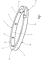
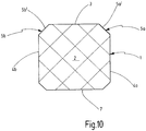
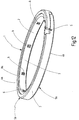
- FIG. 1 As well as in the FIGS. 8 to 10 is a generally designated 1 rectangular seal shown having a sealing body 2 with a lateral surface 3 and two flank surfaces 4a and 4b.
- the rectangular seal 1 has a lock 5, which is designed here as a hook lock 10, which in the following on the basis of FIGS. 2 to 7 is described.
- the sealing body 2 is made of a non-metallic material, in particular a thermoplastic or thermosetting material. Such a rectangular seal is known and therefore need not be described in detail.
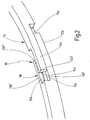
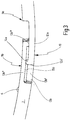
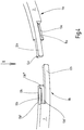
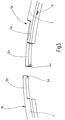
- the hook lock 10 has a first closing element 11a and a second closing element 11b, which engage with each other and thus connect the open sealing body 2 of the rectangular seal 1 into a closed ring and a seal in both the radial and axial directions form.
- first closing element 11a and second closing element 11b engage with each other and thus connect the open sealing body 2 of the rectangular seal 1 into a closed ring and a seal in both the radial and axial directions form.
- the right-hand closing element 11a has a tongue 12a extending in the circumferential direction of the sealing body 2, which tongue has a length I and extends over a defined circumferential region of the sealing body 2.
- a radially inwardly projecting locking element 14a is arranged, so that the tongue 12a together with the locking element 14a seen in the ring cross-section has a hook-like or L-shaped form.
- the tongue 12a and the latching element 14a of the first closing element 11a cooperate with the complementary thereto formed second closing element 11b, which has a circumferentially extending annular sealing body recess 13b and a latching receptacle 15b.
- the recess In this case, 13b again has a length l which corresponds to the length of the tongue 12a of the first closing element 11a, whereby the recess 13b is formed in the limiting bottom 13b 'by the sealing body 2.
- the recess 13b is bounded by a wall 13b "which is formed by the remaining area of the sealing body 2.
- the recess 13b is bounded by a stop element 13b '" cooperating with the locking element 14a.
- the thickness and thus the radial extent of the tongue 12a and the depth of the recess 13b are preferably coordinated such that their sum is equal to the radial or axial extent of the sealing body 2 of the rectangular seal 1, so that the radial Extension of the hook lock 10 is substantially equal to the radial extent of the sealing body 2. This ensures that no significant weakening of the sealing body 2 of the seal 1 occurs in this area by the closing elements 11a, 11b of the hook lock 10.
- the tongue 12 a can thus be inserted into the recess 13 b of the second closing element 11 b and covers its bottom 13 b ', wherein the nose-like locking element 14 a of the first closing element 11 a dips into the receptacle 13 b of the second closing element 11 b, whereby the sealing body 2 of the rectangular seal. 1 is closed in the circumferential direction.
- the second closing element 11b has a tongue 12b corresponding to the tongue 12a of the first closing element 11a, which extends over a length I in the circumferential direction of the annular sealing body 2.
- the tongues 12a and 12b are arranged mirror-symmetrically.
- the first closing element 11a has a recess 13a corresponding to the recess 13b, the bottom 13a ', wall 13a "and stop element 13a"' of which are formed by corresponding regions of the sealing body 2.
- the second tongue 12b can thus be introduced into the recess 13a of the first closing element 11a, so that the tongue 12b and the region of the sealing body 2 forming the bottom 13a 'of the recess 13a overlap when the hook lock 10 is closed.
- an axial seal seen in the axial direction, the tongue 12a in front of the wall 13b "of the recess 13b and the tongue 12b is located in the axial direction behind the wall 13a" of the recess 13a so that overlap each of these areas and thus effect the above-mentioned axial sealing of the hook lock 10 and thus of this hook lock 10 using rectangular seal 1.
- the tongue 12b also has a latching element 14a corresponding latching element 14 and the recess 13a has a locking receptacle 15b corresponding latching receptacle 15a.
- This mirror-symmetrical structure of the two closing elements 11a and 11b has the advantage that care must be taken when inserting the rectangular seal 1 in a sealing arrangement 20 on its orientation, since the thus formed hook lock 10 has a bidirectional seal in the axial direction.
- the configuration of the latch lock 10 described above can be simplified if a double locking of the sealing body 2, as by the cooperating locking elements, namely by the locking element 14a of the first closing element 11a and the locking receptacle 15b of second locking member 11b and the locking element 14b and the locking receptacle 15a is formed is not needed.
- one of the two locking elements for. B. the locking element 14b of the second closing element 11b and with him cooperating locking receptacle 15a accounts, so that the closing of the sealing body 2 of the rectangular seal 1 is effected only by the locking element 14a and cooperating with him locking receptacle 15b.
- the tongue 12b has no latching element 14b and therefore the latching receptacle 15a is likewise omitted.
- the tongue 12b is then received without a latching in the receptacle 13a and thus seals the hook lock 10 and thus the rectangular seal 1 in the axial direction.
- first tongue 12a and the second tongue 12b be the same in the circumferential direction. It is then also possible to form the tongues 12a, 12b and consequently the recesses 13a and 13b cooperating therewith with different lengths I, so that an asymmetrical construction of the hook lock 10 is then provided.
- At least one of the two latching elements 13a and 13b is designed such that it snaps when closing the hook lock 10 in cooperating with him latching receptacle 15a and 15b. This ensures that after closing the hook lock 10 unintentional re-opening the hook lock 10 is prevented.
- FIG. 1 How best of the FIG. 1 can be seen is at the rectangular seal 1 at least one and in the case shown here at both flank surfaces 4a and 4b in each case an insertion element 5a and 5b is arranged. However, it may also be sufficient for certain applications that one or both insertion elements 5a and 5b each only along a portion of the circumference of the Seal body 2 run.
- These insertion elements 5a and 5b serve - as described below - during insertion of the rectangular seal 1 in a passage 21 of a seal assembly 20, the edge region R of this implementation 21 limiting housing G (see FIG. 2 ) of this implementation can slide on the respective insertion bevel 5a or 5b.
- insertion elements 5a and 5b serve - as described below - during insertion of the rectangular seal 1 in a passage 21 of a seal assembly 20, the edge region R of this implementation 21 limiting housing G (see FIG. 11 ) of this implementation can slide on the respective insertion bevel 5a or 5b.
- the radial course of both or at least one insertion element 5a and / or 5b is such that the insertion element 5a and / or 5b begins at least at the point at which the rectangular seal 1 from the groove N of a shaft W (see FIG. 11 ), and that one or both insertion elements 5a, 5b preferably terminate in the transition region between the flank surface 4a or 4b and the outer circumferential surface 3.
- the insertion elements 5a and 5b are formed in the embodiment shown here as Ein Industriesfasen 5a 'and 5b'. Such a measure has the advantage of a particularly simple design of the insertion elements 5a and 5b. However, it is not absolutely necessary that the insertion elements 5a and 5b extend obliquely over their entire area. Rather, this area can also be formed curved or it is also possible that the last area of the insertion elements 5a and 5b, d. H. the area lying just before the outer circumferential surface 3, is radially aligned, d. h., So that a kind of "stage" is realized.
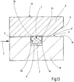
- FIG. 11 is now shown schematically the seal assembly 20, by means of which the installation situation of the rectangular seal 1 is to be explained in a passage 21 and the assembly process.
- the FIG. 11 shows a cross section through such a seal assembly 20 which is rotationally symmetrical to an axis A.
- a housing G has the rotary feedthrough 21, in which a shaft W is inserted. Between the outer surface W 'of the shaft W and the inner surface G' of the housing G, which limits the rotary feedthrough 21, a sealing gap D is present, which is to be sealed by the rectangular seal 1.
- the term "Seal" compliance with a critical fluid or gas leakage is called, the magnitude of this leakage can be quite different depending on the application and must be defined for the individual case.
- the rectangular seal 1 is first inserted into the groove N of the shaft W. This can be done by the rectangular seal 1 expanded, then pushed onto the shaft W and finally to the groove N, in which it is to be placed, moved further and is introduced into the groove N.
- the shaft W is inserted into the feedthrough 21, which is designed as a rotary feedthrough in this case.
- the outer diameter of the shaft W is smaller by the dimension of the sealing gap D than the diameter of the passage 21 defined by the inner wall G 'of the housing G. Since the rectangular seal 1 must close the sealing gap D in the installed state of this dynamic sealing arrangement 20, that its lateral surface 3 rests against the inner wall G 'of the housing G, the groove N of the shaft W inserted rectangular seal 1 at least by the dimension of the sealing gap D on the outer surface W' before.
- the rectangular seal 1 is formed such that its outer surface defined by the outer surface 2 diameter is greater than the sum of the outer diameter of the shaft W and the dimension of the sealing gap D, so that after insertion of the rectangular seal 1 in the seal assembly 20 the Jacket surface 3 of the sealing body 2 against the inner surface G 'of the housing G is pressed.
- the insertion of the area of the shaft W in the leadthrough 21 in front of the rectangular seal 1 mounted in the groove N is generally easily possible, since the outside diameter of the shaft W around the sealing gap D is less than the diameter of the feedthrough 21 Inserted in the groove N used rectangular seal 1 in the passage 21, so the edge region R of the housing G comes into contact with the front in the insertion direction V flank region, here the flank region 4a.
- the described Rectangular seal 1 has, in an advantageous manner, the insertion element 5a formed here as an introduction chamfer 5a ', which runs inclined from the lateral surface 3 to the first flank surface 4a.
- the edge region R of the housing G then slides on insertion of the shaft W in the insertion direction V on the insertion element 5a.
- the risk of damage to the sealing body 2 if not eliminated, at least reduced.
- the described embodiment of the rectangular seal 1 with insertion elements 5a and 5b facilitates the insertion of the rectangular seal 1 into the sealing arrangement 20, especially when the edge region R of the housing G, when the shaft W is moved onto the insertion elements 5a slips on, not - as in FIG. 11 shown - is executed chamfered.
- lateral surface 3 of the rectangular seal 1 of the first and the second embodiment may optionally be provided further hydrodynamic or hydrostatic relief structures.
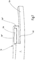
- FIG. 12 and 13 a second embodiment of a rectangular seal 1 is shown, wherein the basic structure of the rectangular seal 1 of the second embodiment corresponds to that of the first embodiment, so that the same or corresponding components are provided with the same reference numerals and will not be described in detail.
- the essential difference between the first and the second embodiment is that in the latter the two flank surfaces 4a and 4b are designed in stages, so that due to these stages 8a and 8b of the flank surfaces 4a and 4b measured in the axial direction width of the lateral surface 3 is less than the width of the base area 7 of the sealing body 2 is.
- a hydrostatic relief structure is formed.
- One of the seal assembly 20 of the first embodiment corresponding, the rectangular seal 1 of the second embodiment using seal assembly 20 is again in FIG. 13 shown.
- the to FIG. 11 The explanations given here apply accordingly.
- lateral surface 3 of the rectangular seal 1 of the first and the second embodiment may optionally be provided further hydrodynamic or hydrostatic relief structures.
- FIG. 14 a third embodiment of a rectangular seal 1 is shown, wherein corresponding components provided with the same reference numerals and will not be described in detail.
- the embodiment shown in the above figure is an internal straining rectangular seal 1.
- Such a rectangular seal 1 is disposed in a groove of the passage 21 delimiting the inner wall G 'of the housing G and the shaft W is thus by the through the inner circumferential surface 7 of the sealing body 2 of the rectangular seal 1 limited interior pushed through.
- the outer lateral surface 3 is received in the assembled state of the rectangular seal 1 in the groove of the inner wall G 'of the housing G and consequently has the elevations 6 in the third embodiment.
- the rectangular seal 1 has in the transition region between the flank surfaces 4a and 4b and the inner circumferential surface 7 provided insertion elements 25a and 25b, which correspond to the insertion elements 5a and 5b of the first two embodiments.
- insertion elements 25a and 25b which correspond to the insertion elements 5a and 5b of the first two embodiments.
- the rectangular seal 1 of the third embodiment on both flank surfaces 4a and 4b each have an insertion element 25a and 25b, so that here also on the orientation of the rectangular seal 1 during insertion does not need to be taken.
- the radial extension of the insertion elements is again such that they preferably begin in the radial direction at the point where the sealing body 2 of the rectangular seal 1 protrudes beyond the edge of the groove provided in the inner wall G ', and that at least one insertion element 25a, 25b extends to the inner circumferential surface 7.
- a rectangular seal 1 it is of course also possible for a rectangular seal 1 to have at least one insertion element 5a and / or 5b assigned to the outer lateral surface 3 and at least one insertion element 25a and / or 25b assigned to the inner lateral surface 7.
- the thus configured seal is in the FIGS. 1 and 8-10. It is therefore suitable in an advantageous manner both for receiving in a groove N of the shaft W and in a groove of the inner wall G 'of the housing G.
- a rectangular seal 1 is formed by the measures described, which is characterized in that at one or both flank surfaces 4a and / or 4b each one at least part of the circumference of the sealing body 2, preferably along the entire circumference, extending Insertion elements 5a and / or 5b or 25a and / or 25b are provided.
- This measure has the advantage that thereby the Danger that during assembly of the rectangular seal 1 in the passage 21 of the seal assembly 20, the sealing body 2 is damaged, at least reduced. It is preferably provided that the insertion elements 5a, 5b or 25a and / or 25b are provided on both flank regions 4a and 4b.
- Such a measure has the advantage that, as a result, when inserting the rectangular seal 1 into the groove N, it is no longer necessary to pay attention to the orientation of the rectangular seal 1.
- the rectangular seal 1 serves to seal the sealing gap D between a shaft W, that is to say a rotating component, and a housing G, ie a stationary component. This is not mandatory.
- the measures described are equally suitable for a rectangular seal for use in a static seal assembly 20, which serves to seal a passage of a fluid or a gas.
Landscapes
- Engineering & Computer Science (AREA)
- General Engineering & Computer Science (AREA)
- Mechanical Engineering (AREA)
- Sealing Devices (AREA)
Claims (11)
- Serrure à crochet pour un joint d'étanchéité rectangulaire qui présente un corps étanche (2) et au moins une paire d'éléments de fermeture (11a, 11b) coopérants, dans laquelle un premier élément de fermeture (11a) est réalisé en forme de crochet et vient en prise avec le second élément de fermeture (11b) réalisé de manière complémentaire à celui-ci pour la fermeture d'un joint d'étanchéité rectangulaire (1), dans laquelle le premier élément de fermeture (11a) possède une languette (12a) ainsi qu'un évidement (13a) et le second élément de fermeture (11b), une autre languette (12b) ainsi qu'un autre évidement (13b), caractérisée en ce que les évidements (13a ; 13b) sont réalisés respectivement par un fond (13a'; 13b') et une paroi (13a" ; 13b") de la zone restante du corps étanche (2), que dans l'état de fermeture de la serrure à crochet (10) dans le sens radial, la languette (12a) du premier élément de fermeture (11a) s'enfonce dans l'évidement (13b) correspondant du second élément de fermeture (11b) et la languette (12b) du second élément de fermeture (11b), dans l'évidement (13a) correspondant du premier élément de fermeture (11a), que dans le sens axial la languette (12a) du premier élément de fermeture (11a) se trouve au-dessus de la paroi (13b") de l'évidement (13b) du second élément de fermeture (11b) et la languette (12b) du second élément de fermeture (11a), au-dessus de la paroi (13a") du premier élément de fermeture (11a), que dans le sens radial la languette (12a) se trouve au-dessus du fond (13b' de l'évidement (13b) du second élément de fermeture (11b) et l'autre languette (12b), au-dessus du fond (13a') de l'évidement (13a) du premier élément de fermeture (11a), et qu'au moins une des languettes (12a ; 12b) présente un élément d'encliquetage (14a ; 14b) en saillie radialement vers l'intérieur et l'évidement (13b ; 13a) correspondant, un logement d'encliquetage (15b ; 15a) pour cet élément d'encliquetage (14a ; 14b) dans lequel l'élément d'encliquetage (14a ; 14b) peut être introduit pour la fermeture de la serrure à crochet (10).
- Serrure à crochet selon la revendication 1, caractérisée en ce que les éléments de fermeture (11a, 11b) sont agencés de manière symétrique.
- Serrure à crochet selon l'une quelconque des revendications précédentes, caractérisée en ce que la longueur d'une languette (12a ; 12b) correspond à la longueur de l'évidement (13b ; 13a) coopérant avec celle-ci.
- Serrure à crochet selon l'une quelconque des revendications précédentes, caractérisée en ce que la somme de l'étendue radiale de l'au moins une languette (12a ; 12b) et de la profondeur de l'évidement (13b ; 13a) coopérant avec celle-ci est identique à l'étendue radiale du corps étanche (2) du joint d'étanchéité rectangulaire (1).
- Joint d'étanchéité rectangulaire pour rendre étanche un passage, qui présente un corps étanche (2) avec une surface enveloppe (3), deux surfaces de flanc (4a, 4b) ainsi qu'une surface de base (7) ainsi qu'une serrure (10) pour la fermeture du corps étanche (2), caractérisé en ce que la serrure est réalisée comme une serrure à crochet (10) selon l'une quelconque des revendications 1 à 4.
- Joint d'étanchéité rectangulaire selon la revendication 5, caractérisé en ce que le joint d'étanchéité rectangulaire (1) présente au moins un élément d'introduction (5a ; 5b ; 25a ; 25b) prévu dans une surface de flanc (4a ; 4b) et tournant au moins le long d'une partie de la périphérie du corps étanche (2).
- Joint d'étanchéité rectangulaire selon la revendication 6, caractérisé en ce qu'un élément d'introduction (5a ; 5b ; 25a ; 25b) est prévu au niveau des deux surfaces de flanc (4a, 4b).
- Joint d'étanchéité rectangulaire selon l'une quelconque des revendications précédentes, caractérisé en ce qu'au moins un élément d'introduction (5a ; 5b ; 25a ; 25b) est réalisé comme un chanfrein d'introduction (5a' ; 5b' ; 25a' ; 25b'), et que de préférence au moins un chanfrein d'introduction (5a' ; 5b' ; 25a' ; 25b') s'étend de manière inclinée entre la surface enveloppe (3) et la surface de flanc (4a ; 4b) associée.
- Joint d'étanchéité rectangulaire selon l'une quelconque des revendications précédentes, caractérisé en ce qu'au moins une surface de flanc (4a ; 4b) présente un étage (8a ; 8b), et que de préférence la largeur axiale de la surface enveloppe (3) du corps étanche (2) du joint d'étanchéité rectangulaire (1) est supérieure à la largeur axiale de la surface de base (7) de ce corps étanche (2).
- Joint d'étanchéité rectangulaire selon l'une quelconque des revendications précédentes, caractérisé en ce que le joint d'étanchéité rectangulaire (1) présente au moins une structure de détente, et que la structure de détente est une structure de détente hydrostatique ou hydrodynamique.
- Agencement de joint d'étanchéité pour rendre étanche un passage (21) pour des fluides ou des gaz entre un premier composant (W) et un second composant (G), dans lequel une rainure (N) est prévue dans le premier composant (W) pour la réception d'un joint d'étanchéité rectangulaire (1), caractérisé en ce que le joint d'étanchéité rectangulaire (1) est réalisé selon l'une quelconque des revendications précédentes, dans lequel de préférence l'agencement de joint d'étanchéité (20) est un agencement de joint d'étanchéité dynamique, que le premier composant est un arbre (W) et le second composant, un boîtier (G) et que le passage (21) est réalisé comme un passage rotatif pour l'arbre (W).
Applications Claiming Priority (3)
| Application Number | Priority Date | Filing Date | Title |
|---|---|---|---|
| DE102014011532.1A DE102014011532A1 (de) | 2014-08-08 | 2014-08-08 | Hakenschloss für eine Rechteckdichtung sowie eine ein derartiges Hakenschloss aufweisende Rechteckdichtung |
| DE202014006271.4U DE202014006271U1 (de) | 2014-08-08 | 2014-08-08 | Hakenschloss für eine Rechteckdichtung sowie eine ein derartiges Hakenschloss aufweisende Rechteckdichtung |
| PCT/EP2015/001609 WO2016020057A1 (fr) | 2014-08-08 | 2015-08-05 | Serrure à crochet destinée à un joint d'étanchéité rectangulaire ainsi que joint d'étanchéité rectangulaire comportant une serrure à crochet de ce type |
Publications (2)
| Publication Number | Publication Date |
|---|---|
| EP3201498A1 EP3201498A1 (fr) | 2017-08-09 |
| EP3201498B1 true EP3201498B1 (fr) | 2019-09-25 |
Family
ID=54035191
Family Applications (1)
| Application Number | Title | Priority Date | Filing Date |
|---|---|---|---|
| EP15757127.4A Active EP3201498B1 (fr) | 2014-08-08 | 2015-08-05 | Serrure à crochet destinée à un joint d'étanchéité rectangulaire ainsi que joint d'étanchéité rectangulaire comportant une serrure à crochet de ce type |
Country Status (2)
| Country | Link |
|---|---|
| EP (1) | EP3201498B1 (fr) |
| WO (1) | WO2016020057A1 (fr) |
Families Citing this family (4)
| Publication number | Priority date | Publication date | Assignee | Title |
|---|---|---|---|---|
| JP6650810B2 (ja) * | 2016-03-31 | 2020-02-19 | 三菱電線工業株式会社 | シールリング |
| FR3050773B1 (fr) * | 2016-04-28 | 2018-05-11 | Poclain Hydraulics Industrie | Machine hydraulique debrayable et vehicule equipe d'une telle machine |
| US20230272858A1 (en) * | 2020-06-09 | 2023-08-31 | Nok Corporation | Sealing structure |
| CN114135668B (zh) * | 2021-11-26 | 2024-04-02 | 济南鸿德橡塑有限公司 | 一种耐磨耐高压密封圈 |
Family Cites Families (5)
| Publication number | Priority date | Publication date | Assignee | Title |
|---|---|---|---|---|
| GB324406A (en) * | 1928-10-27 | 1930-01-27 | Doxford William & Sons Ltd | Improvements in or relating to piston rings |
| US4361337A (en) * | 1979-05-15 | 1982-11-30 | Adriel Montes | Piston ring with tongue and groove joint |
| US4844487A (en) * | 1988-11-04 | 1989-07-04 | Kaydon Corporation | Lock-step duo step split sealing ring |
| JPWO2010084853A1 (ja) * | 2009-01-20 | 2012-07-19 | Nok株式会社 | シールリング |
| EP2557337A1 (fr) * | 2011-08-09 | 2013-02-13 | MTU Aero Engines GmbH | Elément de construction |
-
2015
- 2015-08-05 EP EP15757127.4A patent/EP3201498B1/fr active Active
- 2015-08-05 WO PCT/EP2015/001609 patent/WO2016020057A1/fr not_active Ceased
Non-Patent Citations (1)
| Title |
|---|
| None * |
Also Published As
| Publication number | Publication date |
|---|---|
| WO2016020057A1 (fr) | 2016-02-11 |
| EP3201498A1 (fr) | 2017-08-09 |
Similar Documents
| Publication | Publication Date | Title |
|---|---|---|
| EP2212593B1 (fr) | Joint à expansion, en particulier pour des gaz | |
| DE102010013412A1 (de) | Abgasleitung für ein Kraftfahrzeug und Abgasanlage | |
| DE102014203913A1 (de) | Buchse | |
| EP3201498B1 (fr) | Serrure à crochet destinée à un joint d'étanchéité rectangulaire ainsi que joint d'étanchéité rectangulaire comportant une serrure à crochet de ce type | |
| DE102018114701A1 (de) | Hydrodynamisch wirksamer Dichtring und Drehdurchführung mit einem solchen Dichtring | |
| EP2927541A1 (fr) | Élément d'étanchéité et construction d'un joint de conduite | |
| AT520210B1 (de) | Steckverbindung zwischen zwei je eine Innenauskleidung aus Kunststoff aufweisenden rohrförmigen Werkstücken aus Beton | |
| DE2648519C2 (de) | Klappenabsperrventil | |
| DE102015009421A1 (de) | Stellventil zum Einstellen einer Prozessfluidströmung einer prozesstechnischen Anlage | |
| WO2016020058A1 (fr) | Joint d'étanchéité rectangulaire servant à rendre étanche un passage, destiné en particulier à des fluides | |
| DE102014011532A1 (de) | Hakenschloss für eine Rechteckdichtung sowie eine ein derartiges Hakenschloss aufweisende Rechteckdichtung | |
| DE202014006271U1 (de) | Hakenschloss für eine Rechteckdichtung sowie eine ein derartiges Hakenschloss aufweisende Rechteckdichtung | |
| DE102014111436A1 (de) | Kupplungsanordnung, insbesondere Rohrkupplung | |
| DE102013200986A1 (de) | Dichtungsanordnung | |
| EP1775507B1 (fr) | Raccord pour des tuyaux | |
| DE102018122507A1 (de) | Anschlussvorrichtung für Rohrleitungen mit Leckageanzeige | |
| DE4123392A1 (de) | Wellendichtring | |
| DE102012220652A1 (de) | Nockenwelle | |
| DE102014011534A1 (de) | Rechteckdichtung zur Abdichtung einer Durchführung, insbesonder für Fluide | |
| DE102015010782A1 (de) | Ventil | |
| DE102017122269A1 (de) | Dichtungsanordnung, insbesondere für Radialgelenklager | |
| DE202012008998U1 (de) | Arbeitszylinder | |
| EP2667074B1 (fr) | Système de connexion de tuyaux avec clip de serrage | |
| DE4203370C2 (de) | Verbindung einer Ventilspindel mit einem Ventilgehäuse und Verfahren zur Herstellung der Verbindung | |
| DE102015226513B4 (de) | Bausatz für eine Rohrverbindung und Dichtungs-Ring für eine solche Rohrverbindung |
Legal Events
| Date | Code | Title | Description |
|---|---|---|---|
| STAA | Information on the status of an ep patent application or granted ep patent |
Free format text: STATUS: THE INTERNATIONAL PUBLICATION HAS BEEN MADE |
|
| PUAI | Public reference made under article 153(3) epc to a published international application that has entered the european phase |
Free format text: ORIGINAL CODE: 0009012 |
|
| STAA | Information on the status of an ep patent application or granted ep patent |
Free format text: STATUS: REQUEST FOR EXAMINATION WAS MADE |
|
| 17P | Request for examination filed |
Effective date: 20170628 |
|
| AK | Designated contracting states |
Kind code of ref document: A1 Designated state(s): AL AT BE BG CH CY CZ DE DK EE ES FI FR GB GR HR HU IE IS IT LI LT LU LV MC MK MT NL NO PL PT RO RS SE SI SK SM TR |
|
| AX | Request for extension of the european patent |
Extension state: BA ME |
|
| DAV | Request for validation of the european patent (deleted) | ||
| DAX | Request for extension of the european patent (deleted) | ||
| REG | Reference to a national code |
Ref country code: DE Ref legal event code: R079 Ref document number: 502015010474 Country of ref document: DE Free format text: PREVIOUS MAIN CLASS: F16J0015320000 Ipc: F16J0015327200 |
|
| GRAP | Despatch of communication of intention to grant a patent |
Free format text: ORIGINAL CODE: EPIDOSNIGR1 |
|
| STAA | Information on the status of an ep patent application or granted ep patent |
Free format text: STATUS: GRANT OF PATENT IS INTENDED |
|
| RIC1 | Information provided on ipc code assigned before grant |
Ipc: F16J 15/3272 20160101AFI20190425BHEP |
|
| INTG | Intention to grant announced |
Effective date: 20190523 |
|
| GRAJ | Information related to disapproval of communication of intention to grant by the applicant or resumption of examination proceedings by the epo deleted |
Free format text: ORIGINAL CODE: EPIDOSDIGR1 |
|
| STAA | Information on the status of an ep patent application or granted ep patent |
Free format text: STATUS: REQUEST FOR EXAMINATION WAS MADE |
|
| GRAS | Grant fee paid |
Free format text: ORIGINAL CODE: EPIDOSNIGR3 |
|
| STAA | Information on the status of an ep patent application or granted ep patent |
Free format text: STATUS: GRANT OF PATENT IS INTENDED |
|
| GRAP | Despatch of communication of intention to grant a patent |
Free format text: ORIGINAL CODE: EPIDOSNIGR1 |
|
| GRAA | (expected) grant |
Free format text: ORIGINAL CODE: 0009210 |
|
| STAA | Information on the status of an ep patent application or granted ep patent |
Free format text: STATUS: THE PATENT HAS BEEN GRANTED |
|
| INTC | Intention to grant announced (deleted) | ||
| INTG | Intention to grant announced |
Effective date: 20190816 |
|
| AK | Designated contracting states |
Kind code of ref document: B1 Designated state(s): AL AT BE BG CH CY CZ DE DK EE ES FI FR GB GR HR HU IE IS IT LI LT LU LV MC MK MT NL NO PL PT RO RS SE SI SK SM TR |
|
| REG | Reference to a national code |
Ref country code: GB Ref legal event code: FG4D Free format text: NOT ENGLISH |
|
| REG | Reference to a national code |
Ref country code: CH Ref legal event code: EP |
|
| REG | Reference to a national code |
Ref country code: AT Ref legal event code: REF Ref document number: 1184130 Country of ref document: AT Kind code of ref document: T Effective date: 20191015 |
|
| REG | Reference to a national code |
Ref country code: IE Ref legal event code: FG4D Free format text: LANGUAGE OF EP DOCUMENT: GERMAN |
|
| REG | Reference to a national code |
Ref country code: DE Ref legal event code: R096 Ref document number: 502015010474 Country of ref document: DE |
|
| REG | Reference to a national code |
Ref country code: NL Ref legal event code: MP Effective date: 20190925 |
|
| PG25 | Lapsed in a contracting state [announced via postgrant information from national office to epo] |
Ref country code: FI Free format text: LAPSE BECAUSE OF FAILURE TO SUBMIT A TRANSLATION OF THE DESCRIPTION OR TO PAY THE FEE WITHIN THE PRESCRIBED TIME-LIMIT Effective date: 20190925 Ref country code: LT Free format text: LAPSE BECAUSE OF FAILURE TO SUBMIT A TRANSLATION OF THE DESCRIPTION OR TO PAY THE FEE WITHIN THE PRESCRIBED TIME-LIMIT Effective date: 20190925 Ref country code: NO Free format text: LAPSE BECAUSE OF FAILURE TO SUBMIT A TRANSLATION OF THE DESCRIPTION OR TO PAY THE FEE WITHIN THE PRESCRIBED TIME-LIMIT Effective date: 20191225 Ref country code: SE Free format text: LAPSE BECAUSE OF FAILURE TO SUBMIT A TRANSLATION OF THE DESCRIPTION OR TO PAY THE FEE WITHIN THE PRESCRIBED TIME-LIMIT Effective date: 20190925 Ref country code: BG Free format text: LAPSE BECAUSE OF FAILURE TO SUBMIT A TRANSLATION OF THE DESCRIPTION OR TO PAY THE FEE WITHIN THE PRESCRIBED TIME-LIMIT Effective date: 20191225 Ref country code: HR Free format text: LAPSE BECAUSE OF FAILURE TO SUBMIT A TRANSLATION OF THE DESCRIPTION OR TO PAY THE FEE WITHIN THE PRESCRIBED TIME-LIMIT Effective date: 20190925 |
|
| REG | Reference to a national code |
Ref country code: LT Ref legal event code: MG4D |
|
| PG25 | Lapsed in a contracting state [announced via postgrant information from national office to epo] |
Ref country code: GR Free format text: LAPSE BECAUSE OF FAILURE TO SUBMIT A TRANSLATION OF THE DESCRIPTION OR TO PAY THE FEE WITHIN THE PRESCRIBED TIME-LIMIT Effective date: 20191226 Ref country code: RS Free format text: LAPSE BECAUSE OF FAILURE TO SUBMIT A TRANSLATION OF THE DESCRIPTION OR TO PAY THE FEE WITHIN THE PRESCRIBED TIME-LIMIT Effective date: 20190925 Ref country code: LV Free format text: LAPSE BECAUSE OF FAILURE TO SUBMIT A TRANSLATION OF THE DESCRIPTION OR TO PAY THE FEE WITHIN THE PRESCRIBED TIME-LIMIT Effective date: 20190925 |
|
| PG25 | Lapsed in a contracting state [announced via postgrant information from national office to epo] |
Ref country code: EE Free format text: LAPSE BECAUSE OF FAILURE TO SUBMIT A TRANSLATION OF THE DESCRIPTION OR TO PAY THE FEE WITHIN THE PRESCRIBED TIME-LIMIT Effective date: 20190925 Ref country code: PL Free format text: LAPSE BECAUSE OF FAILURE TO SUBMIT A TRANSLATION OF THE DESCRIPTION OR TO PAY THE FEE WITHIN THE PRESCRIBED TIME-LIMIT Effective date: 20190925 Ref country code: AL Free format text: LAPSE BECAUSE OF FAILURE TO SUBMIT A TRANSLATION OF THE DESCRIPTION OR TO PAY THE FEE WITHIN THE PRESCRIBED TIME-LIMIT Effective date: 20190925 Ref country code: PT Free format text: LAPSE BECAUSE OF FAILURE TO SUBMIT A TRANSLATION OF THE DESCRIPTION OR TO PAY THE FEE WITHIN THE PRESCRIBED TIME-LIMIT Effective date: 20200127 Ref country code: IT Free format text: LAPSE BECAUSE OF FAILURE TO SUBMIT A TRANSLATION OF THE DESCRIPTION OR TO PAY THE FEE WITHIN THE PRESCRIBED TIME-LIMIT Effective date: 20190925 Ref country code: ES Free format text: LAPSE BECAUSE OF FAILURE TO SUBMIT A TRANSLATION OF THE DESCRIPTION OR TO PAY THE FEE WITHIN THE PRESCRIBED TIME-LIMIT Effective date: 20190925 Ref country code: NL Free format text: LAPSE BECAUSE OF FAILURE TO SUBMIT A TRANSLATION OF THE DESCRIPTION OR TO PAY THE FEE WITHIN THE PRESCRIBED TIME-LIMIT Effective date: 20190925 Ref country code: RO Free format text: LAPSE BECAUSE OF FAILURE TO SUBMIT A TRANSLATION OF THE DESCRIPTION OR TO PAY THE FEE WITHIN THE PRESCRIBED TIME-LIMIT Effective date: 20190925 |
|
| PG25 | Lapsed in a contracting state [announced via postgrant information from national office to epo] |
Ref country code: SK Free format text: LAPSE BECAUSE OF FAILURE TO SUBMIT A TRANSLATION OF THE DESCRIPTION OR TO PAY THE FEE WITHIN THE PRESCRIBED TIME-LIMIT Effective date: 20190925 Ref country code: SM Free format text: LAPSE BECAUSE OF FAILURE TO SUBMIT A TRANSLATION OF THE DESCRIPTION OR TO PAY THE FEE WITHIN THE PRESCRIBED TIME-LIMIT Effective date: 20190925 Ref country code: CZ Free format text: LAPSE BECAUSE OF FAILURE TO SUBMIT A TRANSLATION OF THE DESCRIPTION OR TO PAY THE FEE WITHIN THE PRESCRIBED TIME-LIMIT Effective date: 20190925 Ref country code: IS Free format text: LAPSE BECAUSE OF FAILURE TO SUBMIT A TRANSLATION OF THE DESCRIPTION OR TO PAY THE FEE WITHIN THE PRESCRIBED TIME-LIMIT Effective date: 20200224 |
|
| REG | Reference to a national code |
Ref country code: DE Ref legal event code: R097 Ref document number: 502015010474 Country of ref document: DE |
|
| PG2D | Information on lapse in contracting state deleted |
Ref country code: IS |
|
| PG25 | Lapsed in a contracting state [announced via postgrant information from national office to epo] |
Ref country code: DK Free format text: LAPSE BECAUSE OF FAILURE TO SUBMIT A TRANSLATION OF THE DESCRIPTION OR TO PAY THE FEE WITHIN THE PRESCRIBED TIME-LIMIT Effective date: 20190925 Ref country code: IS Free format text: LAPSE BECAUSE OF FAILURE TO SUBMIT A TRANSLATION OF THE DESCRIPTION OR TO PAY THE FEE WITHIN THE PRESCRIBED TIME-LIMIT Effective date: 20200126 |
|
| PLBE | No opposition filed within time limit |
Free format text: ORIGINAL CODE: 0009261 |
|
| STAA | Information on the status of an ep patent application or granted ep patent |
Free format text: STATUS: NO OPPOSITION FILED WITHIN TIME LIMIT |
|
| 26N | No opposition filed |
Effective date: 20200626 |
|
| PG25 | Lapsed in a contracting state [announced via postgrant information from national office to epo] |
Ref country code: SI Free format text: LAPSE BECAUSE OF FAILURE TO SUBMIT A TRANSLATION OF THE DESCRIPTION OR TO PAY THE FEE WITHIN THE PRESCRIBED TIME-LIMIT Effective date: 20190925 |
|
| PG25 | Lapsed in a contracting state [announced via postgrant information from national office to epo] |
Ref country code: MC Free format text: LAPSE BECAUSE OF FAILURE TO SUBMIT A TRANSLATION OF THE DESCRIPTION OR TO PAY THE FEE WITHIN THE PRESCRIBED TIME-LIMIT Effective date: 20190925 |
|
| REG | Reference to a national code |
Ref country code: CH Ref legal event code: PL |
|
| PG25 | Lapsed in a contracting state [announced via postgrant information from national office to epo] |
Ref country code: LU Free format text: LAPSE BECAUSE OF NON-PAYMENT OF DUE FEES Effective date: 20200805 Ref country code: LI Free format text: LAPSE BECAUSE OF NON-PAYMENT OF DUE FEES Effective date: 20200831 Ref country code: CH Free format text: LAPSE BECAUSE OF NON-PAYMENT OF DUE FEES Effective date: 20200831 |
|
| REG | Reference to a national code |
Ref country code: BE Ref legal event code: MM Effective date: 20200831 |
|
| PG25 | Lapsed in a contracting state [announced via postgrant information from national office to epo] |
Ref country code: BE Free format text: LAPSE BECAUSE OF NON-PAYMENT OF DUE FEES Effective date: 20200831 Ref country code: IE Free format text: LAPSE BECAUSE OF NON-PAYMENT OF DUE FEES Effective date: 20200805 |
|
| REG | Reference to a national code |
Ref country code: AT Ref legal event code: MM01 Ref document number: 1184130 Country of ref document: AT Kind code of ref document: T Effective date: 20200805 |
|
| PG25 | Lapsed in a contracting state [announced via postgrant information from national office to epo] |
Ref country code: AT Free format text: LAPSE BECAUSE OF NON-PAYMENT OF DUE FEES Effective date: 20200805 |
|
| PG25 | Lapsed in a contracting state [announced via postgrant information from national office to epo] |
Ref country code: TR Free format text: LAPSE BECAUSE OF FAILURE TO SUBMIT A TRANSLATION OF THE DESCRIPTION OR TO PAY THE FEE WITHIN THE PRESCRIBED TIME-LIMIT Effective date: 20190925 Ref country code: MT Free format text: LAPSE BECAUSE OF FAILURE TO SUBMIT A TRANSLATION OF THE DESCRIPTION OR TO PAY THE FEE WITHIN THE PRESCRIBED TIME-LIMIT Effective date: 20190925 Ref country code: CY Free format text: LAPSE BECAUSE OF FAILURE TO SUBMIT A TRANSLATION OF THE DESCRIPTION OR TO PAY THE FEE WITHIN THE PRESCRIBED TIME-LIMIT Effective date: 20190925 |
|
| PG25 | Lapsed in a contracting state [announced via postgrant information from national office to epo] |
Ref country code: MK Free format text: LAPSE BECAUSE OF FAILURE TO SUBMIT A TRANSLATION OF THE DESCRIPTION OR TO PAY THE FEE WITHIN THE PRESCRIBED TIME-LIMIT Effective date: 20190925 |
|
| PGFP | Annual fee paid to national office [announced via postgrant information from national office to epo] |
Ref country code: DE Payment date: 20240723 Year of fee payment: 10 |
|
| PGFP | Annual fee paid to national office [announced via postgrant information from national office to epo] |
Ref country code: GB Payment date: 20240723 Year of fee payment: 10 |
|
| PGFP | Annual fee paid to national office [announced via postgrant information from national office to epo] |
Ref country code: FR Payment date: 20240823 Year of fee payment: 10 |
|
| REG | Reference to a national code |
Ref country code: DE Ref legal event code: R119 Ref document number: 502015010474 Country of ref document: DE |