EP3201513B1 - Quantenpunkte in geschlossener umgebung - Google Patents
Quantenpunkte in geschlossener umgebung Download PDFInfo
- Publication number
- EP3201513B1 EP3201513B1 EP15763357.9A EP15763357A EP3201513B1 EP 3201513 B1 EP3201513 B1 EP 3201513B1 EP 15763357 A EP15763357 A EP 15763357A EP 3201513 B1 EP3201513 B1 EP 3201513B1
- Authority
- EP
- European Patent Office
- Prior art keywords
- light
- gas
- light source
- wavelength converter
- chamber
- Prior art date
- Legal status (The legal status is an assumption and is not a legal conclusion. Google has not performed a legal analysis and makes no representation as to the accuracy of the status listed.)
- Active
Links
Images


Classifications
-
- F—MECHANICAL ENGINEERING; LIGHTING; HEATING; WEAPONS; BLASTING
- F21—LIGHTING
- F21K—NON-ELECTRIC LIGHT SOURCES USING LUMINESCENCE; LIGHT SOURCES USING ELECTROCHEMILUMINESCENCE; LIGHT SOURCES USING CHARGES OF COMBUSTIBLE MATERIAL; LIGHT SOURCES USING SEMICONDUCTOR DEVICES AS LIGHT-GENERATING ELEMENTS; LIGHT SOURCES NOT OTHERWISE PROVIDED FOR
- F21K9/00—Light sources using semiconductor devices as light-generating elements, e.g. using light-emitting diodes [LED] or lasers
- F21K9/60—Optical arrangements integrated in the light source, e.g. for improving the colour rendering index or the light extraction
- F21K9/64—Optical arrangements integrated in the light source, e.g. for improving the colour rendering index or the light extraction using wavelength conversion means distinct or spaced from the light-generating element, e.g. a remote phosphor layer
-
- F—MECHANICAL ENGINEERING; LIGHTING; HEATING; WEAPONS; BLASTING
- F21—LIGHTING
- F21K—NON-ELECTRIC LIGHT SOURCES USING LUMINESCENCE; LIGHT SOURCES USING ELECTROCHEMILUMINESCENCE; LIGHT SOURCES USING CHARGES OF COMBUSTIBLE MATERIAL; LIGHT SOURCES USING SEMICONDUCTOR DEVICES AS LIGHT-GENERATING ELEMENTS; LIGHT SOURCES NOT OTHERWISE PROVIDED FOR
- F21K9/00—Light sources using semiconductor devices as light-generating elements, e.g. using light-emitting diodes [LED] or lasers
- F21K9/20—Light sources comprising attachment means
- F21K9/23—Retrofit light sources for lighting devices with a single fitting for each light source, e.g. for substitution of incandescent lamps with bayonet or threaded fittings
- F21K9/232—Retrofit light sources for lighting devices with a single fitting for each light source, e.g. for substitution of incandescent lamps with bayonet or threaded fittings specially adapted for generating an essentially omnidirectional light distribution, e.g. with a glass bulb
-
- F—MECHANICAL ENGINEERING; LIGHTING; HEATING; WEAPONS; BLASTING
- F21—LIGHTING
- F21V—FUNCTIONAL FEATURES OR DETAILS OF LIGHTING DEVICES OR SYSTEMS THEREOF; STRUCTURAL COMBINATIONS OF LIGHTING DEVICES WITH OTHER ARTICLES, NOT OTHERWISE PROVIDED FOR
- F21V29/00—Protecting lighting devices from thermal damage; Cooling or heating arrangements specially adapted for lighting devices or systems
- F21V29/50—Cooling arrangements
- F21V29/70—Cooling arrangements characterised by passive heat-dissipating elements, e.g. heat-sinks
-
- F—MECHANICAL ENGINEERING; LIGHTING; HEATING; WEAPONS; BLASTING
- F21—LIGHTING
- F21V—FUNCTIONAL FEATURES OR DETAILS OF LIGHTING DEVICES OR SYSTEMS THEREOF; STRUCTURAL COMBINATIONS OF LIGHTING DEVICES WITH OTHER ARTICLES, NOT OTHERWISE PROVIDED FOR
- F21V31/00—Gas-tight or water-tight arrangements
-
- F—MECHANICAL ENGINEERING; LIGHTING; HEATING; WEAPONS; BLASTING
- F21—LIGHTING
- F21V—FUNCTIONAL FEATURES OR DETAILS OF LIGHTING DEVICES OR SYSTEMS THEREOF; STRUCTURAL COMBINATIONS OF LIGHTING DEVICES WITH OTHER ARTICLES, NOT OTHERWISE PROVIDED FOR
- F21V9/00—Elements for modifying spectral properties, polarisation or intensity of the light emitted, e.g. filters
- F21V9/08—Elements for modifying spectral properties, polarisation or intensity of the light emitted, e.g. filters for producing coloured light, e.g. monochromatic; for reducing intensity of light
-
- F—MECHANICAL ENGINEERING; LIGHTING; HEATING; WEAPONS; BLASTING
- F21—LIGHTING
- F21V—FUNCTIONAL FEATURES OR DETAILS OF LIGHTING DEVICES OR SYSTEMS THEREOF; STRUCTURAL COMBINATIONS OF LIGHTING DEVICES WITH OTHER ARTICLES, NOT OTHERWISE PROVIDED FOR
- F21V9/00—Elements for modifying spectral properties, polarisation or intensity of the light emitted, e.g. filters
- F21V9/30—Elements containing photoluminescent material distinct from or spaced from the light source
- F21V9/32—Elements containing photoluminescent material distinct from or spaced from the light source characterised by the arrangement of the photoluminescent material
-
- F—MECHANICAL ENGINEERING; LIGHTING; HEATING; WEAPONS; BLASTING
- F21—LIGHTING
- F21V—FUNCTIONAL FEATURES OR DETAILS OF LIGHTING DEVICES OR SYSTEMS THEREOF; STRUCTURAL COMBINATIONS OF LIGHTING DEVICES WITH OTHER ARTICLES, NOT OTHERWISE PROVIDED FOR
- F21V9/00—Elements for modifying spectral properties, polarisation or intensity of the light emitted, e.g. filters
- F21V9/40—Elements for modifying spectral properties, polarisation or intensity of the light emitted, e.g. filters with provision for controlling spectral properties, e.g. colour, or intensity
- F21V9/45—Elements for modifying spectral properties, polarisation or intensity of the light emitted, e.g. filters with provision for controlling spectral properties, e.g. colour, or intensity by adjustment of photoluminescent elements
-
- F—MECHANICAL ENGINEERING; LIGHTING; HEATING; WEAPONS; BLASTING
- F21—LIGHTING
- F21Y—INDEXING SCHEME ASSOCIATED WITH SUBCLASSES F21K, F21L, F21S and F21V, RELATING TO THE FORM OR THE KIND OF THE LIGHT SOURCES OR OF THE COLOUR OF THE LIGHT EMITTED
- F21Y2101/00—Point-like light sources
-
- F—MECHANICAL ENGINEERING; LIGHTING; HEATING; WEAPONS; BLASTING
- F21—LIGHTING
- F21Y—INDEXING SCHEME ASSOCIATED WITH SUBCLASSES F21K, F21L, F21S and F21V, RELATING TO THE FORM OR THE KIND OF THE LIGHT SOURCES OR OF THE COLOUR OF THE LIGHT EMITTED
- F21Y2115/00—Light-generating elements of semiconductor light sources
- F21Y2115/10—Light-emitting diodes [LED]
Definitions
- WO2011/053635 describes a light-emitting diode (LED) device, comprising: (a) a blue-light emitting LED; and (b) a hermetically sealed container comprising a plurality of luminescent nanocrystals, wherein the container is placed with respect to the LED to facilitate down- conversion of the luminescent nanocrystals.
- LED light-emitting diode
- JP2012009712 describes a light emitting device comprising a semiconductor laser emitting laser light and a light emitting part receiving excitation light emitted from the semiconductor laser and emitting light.
- the semiconductor laser and the light emitting part are provided in an airtight space, and dry air having a moisture content not more than a predetermined moisture content is filled in the airtight space.
- Quantum dots are currently being studied as phosphors in solid state lighting (SSL) applications (LEDs). They have several advantages such as a tunable emission and a narrow emission band which can help to significantly increase the efficacy of LED based lamps, especially at high CRI.
- qdots are supplied in an organic liquid, with the quantum dots surrounded by organic ligands, such as oleate (the anion of oleic acid), which helps to improve the emission efficiency of the dots as well as stabilize them in organic media.
- organic ligands such as oleate (the anion of oleic acid)
- hydrolyzed TEOS has a high affinity for the QD surface and replaces the hydrophobic amine ligands, which enables the transfer of the QDs to the hydrophilic interior of the micelles where silica growth takes place.
- the position of the incorporated QDs could be controlled from centered to off-center and eventually to the surface of the silica spheres. They were able to make QD/silica particles with an unprecedented quantum efficiency of 35%.
- Silica encapsulation of QDs see also above, is (thus) used to stabilize the QDs in air and to protect them from chemical interactions with the outside.
- the reverse micelle method was introduced in the 90's as a method to make small ( ⁇ 20 nm) silica particles with a small size dispersion (see below).
- This method can also be used to make silica-coated QDs.
- the native organic ligands around QDs are replaced by inorganic silica precursor molecules during the silica shell growth.
- the inorganic silica shell around QDs has the promise to make QDs more stable against photooxidation, because the organic ligands are seen as the weak chain in conventional (e.g. oleic acid or hexadecylamine) capped QDs.
- silica as grown by the reverse micelle method appears to be relatively porous, making it a less good barrier against oxygen or water than sometimes suggested.
- the stability in ambient conditions is less than in general desired, and it was found that especially water is the root cause for degradation of such QDs.
- QE quantum efficiency
- color point stability over time which are less than desirable. For instance, a large initial QE drop may be percieved, or a photo brightening effect may be percieved, and/or a color point change during life time may be percieved.
- silica coated QDs require a certain amount of water to ensure optimal performance (both QE and stability). Especially when QDs are used within a hermetically sealed light bulb, it surprisingly appears that it is important to include a sufficient amount of water.
- a specific example of such an application is a helium cooled LED bulb, where a number of LEDs are placed in a hermetically sealed glass bulb (using the process used for conventional incandescent light bulbs) under a helium atmosphere. Because of the unique cooling properties of helium, limited additional heat sinking is required in such a lamp architecture, saving significant costs.
- the invention provides a lighting device comprising a closed chamber with a light transmissive window and a light source configured to provide light source radiation into the chamber, wherein the chamber further encloses a wavelength converter configured to convert at least part of the light source radiation into wavelength converter light, wherein the light transmissive window is transmissive for the wavelength converter light, wherein the wavelength converter comprises luminescent quantum dots which upon excitation with at least part of the light source radiation generate at least part of said wavelength converter light, and wherein the closed chamber comprises a filling gas, especially comprising one or more of helium gas, hydrogen gas (H 2 ), nitrogen gas (N 2 ) and oxygen gas (O 2 ), and (the filling gas) especially having a relative humidity (RH) at 19 °C of at least 1%, such as especially at least 5%, but especially lower than 100% (at 19 °C), such as in the range of 5-95%, like 10-85%.
- a filling gas especially comprising one or more of helium gas, hydrogen gas (H 2 ), nitrogen gas
- the filling gas especially has a relative high thermal conductivity, such as the indicated helium, hydrogen, nitrogen and oxygen gas, even more especially at least one or more of helium and hydrogen.
- the filling gas may also be applied as cooling gas (optionally in combination with a heat sink (see also below)).
- the filling gas is relative inert, such as helium, hydrogen and nitrogen, even more especially helium and nitrogen.
- the filling gas may especially comprise helium.
- the closed chamber with a light transmissive window is configured to host the wavelength converter.
- the wavelength converter is thus especially enclosed by the closed chamber.
- the chamber may comprise a wall, the wall providing said closed chamber.
- the term "wall" may also refer to a plurality of walls and may optionally comprise more than one element.
- part of the wall may be provided by an element or support comprising the light source and e.g. electronics and a heat sink, and may e.g. include also a PCB (printed circuit board).
- the light source may also be enclosed by the chamber.
- the light source may also be external from the chamber.
- part of the light source is outside of the chamber and part of the light source, especially a light emissive surface, may be within the chamber.
- the light source When the light source is configured outside the chamber, or when the light emissive surface of such light source is configured outside the chamber, the light source will be configured to provide light source radiation into the chamber via a radiation transmissive window.
- the chamber may include a radiation transmissive window that is transmissive for at least part of the light source radiation.
- the wall(s) of the chamber are especially gas tight, i.e. that substantially no gas leaks away from the chamber or is introduced from external of the chamber into the chamber after closing the chamber.
- the wall(s), including the light transmissive window (and optionally the radiation transmissive window) is especially gas-tight.
- the gas chamber may thus especially hermitically sealed.
- the wall(s) may e.g. include inorganic material.
- the wall(s) may include an organic material, e.g. covered with a layer of an (e.g. inorganic) gas-tight material. Combinations of inorganic wall parts and organic wall parts may also be possible.
- the lighting device further comprises a heat sink in thermal contact with one or more of the transmissive window, the light source and the wavelength converter. Together with the filling gas, this may provide a good thermal control and will reduce operating temperature.
- thermal contact may in an embodiment mean physical contact and may in another embodiment mean in contact via a (solid) thermal conductor.
- the wavelength converter may include one or more luminescent materials, but at least comprises quantum dots. These quantum dots are responsible for at least part of the wavelength converter light.
- the luminescent quantum dots are configured to generate at least part of the wavelength converter light upon excitation with at least part of the light source radiation.
- the luminescence of the wavelength converter should escape from the chamber.
- the chamber comprises a light transmissive window.
- the light transmissive window comprises a solid material that is transmissive for at least part of the visible light generated by the wavelength converter.
- the radiation transmissive window may comprise the light transmissive window. However, optionally these are different parts from of the chamber (wall).
- the device is especially configured to generate lighting device light, which at least partly comprises the wavelength converter light, but which may optionally also comprise (remaining) light source radiation.
- the wavelength converter may be configured to only partly convert the light source radiation.
- the device light may comprise converter light and light source radiation.
- the wavelength converter may also be configured to convert all the light source radiation.
- the lighting device is configured to provide lighting device light comprising both light source radiation and converter light, for instance the former being blue light, and the latter comprising yellow light, or yellow and red light, or green and red light, or green, yellow and red light, etc.
- the lighting device is configured to provide lighting device light comprising only converter light. This may for instance happen (especially in transmissive mode) when light source radiation irradiating the wavelength converter only leaves the downstream side of the wavelength converter as converted light (i.e. all light source radiation penetrating into the wavelength converter is absorbed by the wavelength converter).
- the converter light and optional remaining light source radiation (remaining downstream of the wavelength converter)).
- the color of the device light may be tunable.
- Other options to make white light are also possible (see also below).
- the lighting device comprises a plurality of light source, then these may optionally be controlled independently (with an (external) control unit).
- the second luminescent material may comprise one or more luminescent materials selected from the group consisting of a divalent europium containing nitride luminescent material or a divalent europium containing oxonitride luminescent material, such as one or more materials selected from the group consisting of (Ba,Sr,Ca)S:Eu, (Mg,Sr,Ca)AlSiN 3 :Eu and (Ba,Sr,Ca) 2 Si 5 N 8 :Eu.
- a divalent europium containing nitride luminescent material or a divalent europium containing oxonitride luminescent material, such as one or more materials selected from the group consisting of (Ba,Sr,Ca)S:Eu, (Mg,Sr,Ca)AlSiN 3 :Eu and (Ba,Sr,Ca) 2 Si 5 N 8 :Eu.
- the second luminescent material may also comprise one or more luminescent materials selected from the group consisting of a trivalent cerium containing garnet and a trivalent cerium containing oxonitride.
- the oxonitride materials are in the art often also indicated as oxynitride materials.
- Such cerium containing garnet may be indicated with the general formula A 3 B 5 O 12 :Ce 3+ , wherein A may comprise one or more of Y, Sc, La, Gd, Tb and Lighting unit, and wherein B comprises one or more of Al and Ga.
- A comprises one or more of Y, Gd and Ly
- B comprises one or more of Al and Ga, especially at least (or only) Al.
- the cerium containing garnet may especially comprise (Y,Gd,Lu) 3 (Al,Ga) 5 O 12 :Ce 3+ class).
- Examples of members within this class are Y 3 Al 5 O 12 :Ce 3+ and Lu 3 Al 5 O 12 :Ce 3+ , etc.
- the second luminescent material may also comprise a tetravalent manganese doped material.
- members of the G 2 ZF 6 :Mn class may be relevant, wherein G is selected from the group of alkaline elements (such as Li, Na, K, etc.) and wherein Z is selected from the group of Si, Ge, Ti, Hf, Zr, Sn.
- This class is herein also indicated as the K 2 SiF 6 :Mn class, which is the class of complex fluoride systems.
- the materials within this class have a cubic Hieratite or hexagonal Demartinite type crystal structure.
- An example of a member within this class is K 2 SiF 6 :Mn (IV; i.e. tetravalent manganese).
- the second luminescent material may also comprise an organic luminescent material, such as a perylene derivative.
- class or “group” herein especially refers to a group of materials that have the same crystallographic structure. Further, the term “class” may also include partial substitutions of cations and/or anions. For instance, in some of the above-mentioned classes Al-O may partially be replaced by Si-N (or the other way around).
- the fact that the above indicated luminescent materials are indicated to be doped with europium (Eu), or cerium (Ce), or manganese (Mn) does not exclude the presence of co-dopants, such the Eu,Ce, wherein europium is co-doped with cerium, Ce,Pr, wherein cerium is codoped with praseodymium, Ce,Na, wherein cerium is codoped with sodium, Ce,Mg, wherein cerium is codoped with magnesium, Ce,Ca, wherein cerium is codoped with calcium, etc., etc. Codoping is known in the art and is known to sometimes enhance the quantum efficiency and/or to tune the emission spectrum.
- the light transmissive window (and/or optionally also the radiation transmissive window) may comprises one or more materials selected from the group consisting of a transmissive organic material support, such as selected from the group consisting of PE (polyethylene), PP (polypropylene), PEN (polyethylene napthalate), PC (polycarbonate), polymethylacrylate (PMA), polymethylmethacrylate (PMMA) (Plexiglas or Perspex), cellulose acetate butyrate (CAB), silicone, polyvinylchloride (PVC), polyethylene terephthalate (PET), (PETG) (glycol modified polyethylene terephthalate), PDMS (polydimethylsiloxane), and COC (cyclo olefin copolymer).
- a transmissive organic material support such as selected from the group consisting of PE (polyethylene), PP (polypropylene), PEN (polyethylene napthalate), PC (polycarbonate), polymethylacrylate (PM
- the light transmissive window may comprise an inorganic material.
- Preferred inorganic materials are selected from the group consisting of glasses, (fused) quartz, transmissive ceramic materials, and silicones. Also hybrid materials, comprising both inorganic and organic parts may be applied. Especially preferred are PMMA, transparent PC, or glass as material for the light transmissive window (and/or optionally also the radiation transmissive window).
- the light transmissive window may be substantially transparent but may alternatively (independently) be selected to be translucent.
- material may be embedded in the window to increase translucency and/or the window may be frosted (such as with sand blasting) (see further also below).
- the elements within the chamber may be less or may be not visible, which may be desirable.
- the light transmissive window and the option radiation transmissive window light (radiation) transmissive material is applied.
- the material has a light transmission in the range of 50-100 %, especially in the range of 70-100%, for light generated by the luminescent material, i.e.
- the support cover is transmissive for visible light from the luminescent material.
- the transmission or light permeability can be determined by providing light at a specific wavelength with a first intensity to the material and relating the intensity of the light at that wavelength measured after transmission through the material, to the first intensity of the light provided at that specific wavelength to the material (see also E-208 and E-406 of the CRC Handbook of Chemistry and Physics, 69th edition, 1088-1989).
- the closed chamber comprises a light bulb shaped light transmissive window.
- a kind of retrofit incandescent lamp can be provided.
- other retrofit type chambers may also be applied, like tubular chambers (T-lamps, such as a T8 tube), etc..
- the chamber may also be formed in other shapes and may also be used to replace an existing lighting fixture.
- the chamber comprises a filling gas comprising one or more of helium gas, hydrogen gas, nitrogen gas and oxygen gas and having a relative humidity at 19 °C of at least 1%, such as especially at least 5%, but especially lower than 100%, such as in the range of 5-95%, like 10-85% (at 19 °C).
- the upper range is especially lower than 100%, such that when the light source is used at a temperature lower than 19 °C, there is (substantially) no condensation of water.
- especially the relative humidity at 19 °C is 95% or lower, such a 90% or lower, like 85% or lower, such as at maximum 80%.
- the lower limit of 1% is especially chosen to provide the desired stability effect (see also above).
- a lower limit of at least 5% relative humidity may provide the desired stability effect.
- the Karl Fischer analysis may be applied, which is known in the art. This analysis is also known as Karl Fisch titration.
- the relative humidity is a ratio, expressed in percent, of the amount of H 2 O present in a gas (the partial pressure of water vapor) relative to the amount that would be present if the gas were saturated (the equilibrium vapor pressure of water).
- helium as atmosphere, and/or optionally one or more other high thermal conductivity gas(ses), for the quantum dots is beneficial.
- the helium gas and/or other gasses are used for cooling. Cooling is important for LED efficiency.
- a lower temperature will in general mean longer stability (lifetime) and higher lm/W efficiency (due to higher QE).
- the presence of some H 2 O is further beneficial.
- at least 70% (not including H 2 O), such as especially at least 75%, such as at least 80%, of the filling gas consists of He.
- the percentage refers to volume percentages.
- the presence of some oxygen may surprisingly also be beneficial.
- the filling gas comprises (at least) helium and oxygen.
- at least 95%, such as at least 99% of the filling gas consists of He and O 2 , and wherein the gas comprises at maximum 30% oxygen, such as at maximum 25% oxygen, like at maximum 20% oxygen. Larger amounts of oxygen may be less desirable in view of amongst others thermal energy management and also stability of the lighting device.
- gasses that may be available may be selected from the (other) noble gasses, H 2 and N 2 , especially H 2 and N 2 .
- the RH is at least 1%, even more at least 5%, such as at least 10%.
- the chamber does not contain liquid water.
- the quantum dots may optionally also be embedded in a matrix.
- the quantum dots may be (homogeneously) dispersed in a (polymeric) matrix.
- Matrices of specific interest are siloxanes (which are often also indicated as silicones).
- a siloxane may be obtained with known siloxane production processes wherein the quantum dots are dispersed.
- the wavelength converter comprises a siloxane matrix wherein the luminescent quantum dots are embedded.
- Relevant siloxane matrices comprise e.g. one or more of polydimethylsiloxane (PDMS) and polydiphenylsiloxane (PDPhS).
- matrices may be applied, such as one or more of a silazane and an acrylate. Even though the QDs are embedded in a matrix it appears that the gas conditions as defined herein are beneficial for the light device (especially QD) properties. Such matrices may not be completely impermeable for water. Hence, even when the QDs are embedded in a (silicone) matrix, the filling gas as indicated above is desirable.
- Quantum dots may be provided as bare particles, or may e.g. be provided as core-shell particles.
- the term "shell” may also refer to a plurality of shells.
- core-shell particles are not necessarily spherical; they may e.g. also be of the quantum rod type or tetrapod type (or other multipod type), etc.. Further examples are provided below.
- the bare particle or core is the optically active part.
- the shell is used as a kind of protection and often comprises a similar type of material, such as a ZnSe core and a ZnS shell (see also below).
- Such particles are commercially available in organic liquids, with organic ligands attached to such particles for better dispersion.
- the outer layer of the particle is the layer most remote from a central part of the bare particle or the core.
- this outer layer would be the ZnS surface of the QD.
- the invention is, however, not limited to quantum dots whit a ZnS shell and a ZnSe core. Below, a number of alternative quantum dots are described.
- the coating process is executed in micelles containing said quantum dots, especially using the reverse-micelle method, as also discussed in Koole et al., which is herein incorporated by reference.
- the coating process is especially a process wherein the coating, especially an oxide coating, even more especially a silica coating, is provided to the outer layer of the QD, and which coating process is especially performed in micelles, wherein the QD is enclosed.
- a micelle may especially be defined as an aggregate of surfactant molecules dispersed in a liquid medium.
- the quantum dots may also comprise coated quantum dots, such as e.g. core-shell QDs comprising a silica coating.
- the coating comprises a silica (SiO 2 ) coating.
- the coating may comprise a titania (TiO 2 ) coating, an alumina (Al 2 O 3 ) coating, or a zirconia (ZrO 2 ) coating.
- TiO 2 titania
- Al 2 O 3 alumina
- ZrO 2 zirconia
- the coating is especially provided in a wet-chemical approach. Further, the coating is especially an inorganic coating.
- the luminescent quantum dots comprise an inorganic coating.
- the gas conditions as defined herein are beneficial for the light device (especially QD) properties. Also such coatings, especially obtainable via a wet-chemical process, may not be completely impermeable for water. Hence, even when the QDs are coated, the filling gas as indicated above is desirable.
- the luminescent quantum dots comprise an inorganic coating, wherein the wavelength converter comprises a (siloxane) matrix wherein the luminescent quantum dots, with said inorganic coating, are embedded.
- the luminescent nanoparticles may for instance be group III-V compound semiconductor quantum dots selected from the group consisting of GaN, GaP, GaAs, AlN, AlP, AlAs, InN, InP, InAs, GaNP, GaNAs, GaPAs, AlNP, AlNAs, AlPAs, InNP, InNAs, InPAs, GaAlNP, GaAlNAs, GaAlPAs, GaInNP, GaInNAs, GaInPAs, InAlNP, InAlNAs, and InAlPAs.
- the luminescent nanoparticles may for instance be I-III-VI2 chalcopyrite-type semiconductor quantum dots selected from the group consisting of CuInS 2 , CuInSe 2 , CuGaS 2 , CuGaSe 2 , AgInS 2 , AgInSe 2 , AgGaS 2 , and AgGaSe 2 .
- the luminescent nanoparticles may for instance be I-V-VI2 semiconductor quantum dots, such as selected from the group consisting of LiAsSe 2 , NaAsSe 2 and KAsSe 2 .
- the dopant elements could be selected from Mn, Ag, Zn, Eu, S, P, Cu, Ce, Tb, Au, Pb, Tb, Sb, Sn and Tl.
- the luminescent nanoparticles based luminescent material may also comprise different types of QDs, such as CdSe and ZnSe:Mn.
- the semiconductor based luminescent quantum dots comprise II-VI quantum dots, especially selected from the group consisting of CdS, CdSe, CdTe, ZnS, ZnSe, ZnTe, HgS, HgSe, HgTe, CdSeS, CdSeTe, CdSTe, ZnSeS, ZnSeTe, ZnSTe, HgSeS, HgSeTe, HgSTe, CdZnS, CdZnSe, CdZnTe, CdHgS, CdHgSe, CdHgTe, HgZnS, HgZnSe, HgZnTe, CdZnSeS, CdZnSeTe, CdZnSTe, CdHgSeS, CdHgSeTe, CdHgSTe, HgZnSeS, CdHgSeTe, CdHgSTe, Hg
- the wavelength converter nano-particles comprise III-V QDs, more specifically an InP based quantum dots, such as a core-shell InP-ZnS QDs.
- InP quantum dot or “InP based quantum dot” and similar terms may relate to "bare” InP QDs, but also to core-shell InP QDs, with a shell on the InP core, such as a core-shell InP-ZnS QDs, like a InP-ZnS QDs dot-in-rod.
- the luminescent nanoparticles may have dimensions in the range of about 1-50 nm, especially 1-20 nm, such as 1-15 nm, like 1-5 nm; especially at least 90 % of the nanoparticles have dimension in the indicated ranges, respectively, (i.e. e.g. at least 90% of the nanoparticles have dimensions in the range of 2-50 nm, or especially at least 90% of the nanoparticles have dimensions in the range of 5-15 nm).
- the term "dimensions" especially relate to one or more of length, width, and diameter, dependent upon the shape of the nanoparticle.
- the wavelength converter nanoparticles have an average particle size in a range from about 1 to about 1000 nanometers (nm), and preferably in a range from about 1 to about 100 nm. In an embodiment, nanoparticles have an average particle size in a range from about 1-50 nm, especially 1 to about 20 nm, and in general at least 1.5 nm, such as at least 2 nm. In an embodiment, nanoparticles have an average particle size in a range from about 1 to about 20 nm.
- Typical dots may be made of binary alloys such as cadmium selenide, cadmium sulfide, indium arsenide, and indium phosphide. However, dots may also be made from ternary alloys such as cadmium selenide sulfide. These quantum dots can contain as few as 100 to 100,000 atoms within the quantum dot volume, with a diameter of 10 to 50 atoms. This corresponds to about 2 to 10 nanometers. For instance, (spherical) particles such as CdSe, InP, or CuInSe 2 , with a diameter of about 3 nm may be provided.
- the luminescent nanoparticles may have the shape of spherical, cube, rods, wires, disk, multi-pods, etc., with the size in one dimension of less than 10 nm.
- nanorods of CdSe with the length of 20 nm and a diameter of 4 nm may be provided.
- the semiconductor based luminescent quantum dots comprise core-shell quantum dots.
- the semiconductor based luminescent quantum dots comprise dots-in-rods nanoparticles. A combination of different types of particles may also be applied.
- core-shell particles and dots-in-rods may be applied and/or combinations of two or more of the afore-mentioned nano particles may be applied, such as CdS and CdSe.
- the term "different types" may relate to different geometries as well as to different types of semiconductor luminescent material.
- a combination of two or more of (the above indicated) quantum dots or luminescent nano-particles may also be applied.
- the quantum dots have a shape selected from the group consisting of a sphere, a cube, a rod, a wire, a disk, and a multi-pod, etc.
- a combination of different types of particles may also be applied.
- the term “different types” may relate to different geometries as well as to different types of semiconductor luminescent material.
- a combination of two or more of (the above indicated) quantum dots or luminescent nano-particles may also be applied.
- nanoparticles or QDs can comprise semiconductor nanocrystals including a core comprising a first semiconductor material and a shell comprising a second semiconductor material, wherein the shell is disposed over at least a portion of a surface of the core.
- a semiconductor nanocrystal or QD including a core and shell is also referred to as a "core/shell" semiconductor nanocrystal.
- the semiconductor nanocrystal or QD can include a core having the formula MX, where M can be cadmium, zinc, magnesium, mercury, aluminum, gallium, indium, thallium, or mixtures thereof, and X can be oxygen, sulfur, selenium, tellurium, nitrogen, phosphorus, arsenic, antimony, or mixtures thereof.
- Examples of materials suitable for use as semiconductor nanocrystal cores include, but are not limited to, ZnO, ZnS, ZnSe, ZnTe, CdO, CdS, CdSe, CdTe, MgS, MgSe, GaAs, GaN, GaP, GaSe, GaSb, HgO, HgS, HgSe, HgTe, InAs, InN, InP, InSb, AlAs, AIN, AlP, AlSb, TIN, TIP, TlAs, TlSb, PbO, PbS, PbSe, PbTe, Ge, Si, an alloy including any of the foregoing, and/or a mixture including any of the foregoing, including ternary and quaternary mixtures or alloys.
- the shell can be a semiconductor material having a composition that is the same as or different from the composition of the core.
- the shell comprises an overcoat of a semiconductor material on a surface of the core semiconductor nanocrystal can include a Group IV element, a Group II-VI compound, a Group II-V compound, a Group III- VI compound, a Group III-V compound, a Group IV-VI compound, a Group I-III-VI compound, a Group II-IV-VI compound, a Group II-IV-V compound, alloys including any of the foregoing, and/or mixtures including any of the foregoing, including ternary and quaternary mixtures or alloys.
- Examples include, but are not limited to, ZnO, ZnS, ZnSe, ZnTe, CdO, CdS, CdSe, CdTe, MgS, MgSe, GaAs, GaN, GaP, GaSe, GaSb, HgO, HgS, HgSe, HgTe, InAs, InN, InP, InSb, AlAs, AIN, AlP, AlSb, TIN, TIP, TlAs, TlSb, PbO, PbS, PbSe, PbTe, Ge, Si, an alloy including any of the foregoing, and/or a mixture including any of the foregoing.
- ZnS, ZnSe or CdS overcoatings can be grown on CdSe or CdTe semiconductor nanocrystals.
- An overcoating process is described, for example, in U.S. Patent 6,322,901 .
- the overcoating comprises at least one semiconductor material which is the same as or different from the composition of the core.
- the overcoating has a thickness from about one to about ten monolayers.
- An overcoating can also have a thickness greater than ten monolayers.
- more than one overcoating can be included on a core.
- semiconductor nanocrystal (core)shell materials include, without limitation: red (e.g., (CdSe)ZnS (core)shell), green (e.g., (CdZnSe)CdZnS (core)shell, etc.), and blue (e.g., (CdS)CdZnS (core)shell (see further also above for examples of specific wavelength converter nanoparticles, based on semiconductors.
- red e.g., (CdSe)ZnS (core)shell
- green e.g., (CdZnSe)CdZnS (core)shell, etc.
- blue e.g., (CdS)CdZnS (core)shell
- quantum dots is luminescent nanocrystal.
- the above-mentioned outer surface may be the surface of a bare quantum dot (i.e. a QD not comprising a further shell or coating) or may be the surface of a coated quantum dot, such as a core-shell quantum dot (like core-shell or dot-in-rod), i.e. the (outer) surface of the shell.
- a coated quantum dot such as a core-shell quantum dot (like core-shell or dot-in-rod), i.e. the (outer) surface of the shell.
- the grafting ligand thus especially grafts to the outer surface of the quantum dot, such as the outer surface of a dot-in-rod QD.
- the cores and shells comprise the same class of material, but essentially consist of different materials, like a ZnS shell surrounding a CdSe core, etc.
- the quantum dots comprise core/shell luminescent nanocrystals comprising CdSe/ZnS, InP/ZnS, PbSe/PbS, CdSe/CdS, CdTe/CdS or CdTe/ZnS.
- the lighting device as described above may be obtainable in different ways. For instance, part of the processing may be done in the indicated filling gas, thereby allowing the chamber to be filled with the filling gas followed by a closing of the chamber with a closure.
- the lighting device may substantially be assembled, but the chamber may include a gas stem for filling the chamber with the filling gas. After filling the chamber, the gas stem may be closed with a closure.
- part of the gas atmosphere may be provided by a material in the (closed) chamber that releases one or more of the components.
- the phrase "filling gas (especially) comprising one or more of helium gas, hydrogen gas, nitrogen gas and oxygen gas and gaseous water at 19 °C" and similar phrases does not mean that the filling gas is provided to the chamber at this temperature.
- the gasses may be provided separately, the H 2 O may be provided as water, etc.
- the filling gas is such that when the chamber is closed and the filling gas is in the chamber, at 19 °C the filling gas comprises helium and/or one or more of the other gasses, and gaseous water. Further, at this temperature the chamber will especially not comprise liquid water.
- the phrase "filling gas comprising one or more of helium gas, hydrogen gas, nitrogen gas and oxygen gas (and gaseous water at 19 °C)" and similar phrases include that in embodiments the pressure within the chamber may be - at least during operation of the lamp - different from about 1 bar, such as e.g. 0.5-1.5 bar, like e.g. 0.5-1 bar, like 0.7-0.9 bar.
- the chamber may include the gas at a pressure of substantially more than 1 bar.
- the chamber comprises gaseous water. Further, at this temperature and pressure the chamber will especially not comprise liquid water.
- upstream and downstream relate to an arrangement of items or features relative to the propagation of the light from a light generating means (here the especially the first light source), wherein relative to a first position within a beam of light from the light generating means, a second position in the beam of light closer to the light generating means is “upstream”, and a third position within the beam of light further away from the light generating means is “downstream”.
- the light source is configured to provide blue light source radiation and the wavelength converter is configured to convert at least part of the light source radiation into wavelength converter light having one or more of a green component, a yellow component, an orange component and a red component.
- the lighting device may provide white light.
- the lighting device may, in addition to the light source configured to provide excitation light to the quantum dots, also include one or more light sources, especially solid state light sources that are not primarily configured to provide radiation to the quantum dots to be wavelength converted by these quantum dots.
- the lighting device may also include a blue and/or green and/or yellow and/or orange and/or red LED. With such lighting device, the lighting device light may further be color tuned.
- the term "green component" and similar terms indicate that the optical spectrum will show intensity in the green (or otherwise indicated) wavelength range.
- substantially herein, such as in “substantially all light” or in “substantially consists”, will be understood by the person skilled in the art.
- the term “substantially” may also include embodiments with “entirely”, “completely”, “all”, etc. Hence, in embodiments the adjective substantially may also be removed.
- the term “substantially” may also relate to 90% or higher, such as 95% or higher, especially 99% or higher, even more especially 99.5% or higher, including 100%.
- the term “comprise” includes also embodiments wherein the term “comprises” means “consists of”.
- the term “and/or” especially relates to one or more of the items mentioned before and after "and/or”.
- Fig. 1a schematically depicts a quantum dot based luminescent material.
- QDs indicated with reference 30
- the QD at the top left is a bare QD, without shell.
- the QD is indicated with C (core).
- the QD 30 at the right top is a core-shell particle, with C again indicating the core, and S indicating the shell.
- C core
- S indicating the shell.
- Reference 36 indicates the outer layer, which is in the first example the core material at the external surface, and which is in the latter two embodiments the shell material at the external surface of the QD 30.
- Fig. 1b schematically depicts an embodiment of the luminescent material, but now the QDs 30 including the coating 45, especially an oxide coating, such as a silica coating.
- the thickness of the coating is indicated with reference d1.
- the thickness may especially be in the range of 1-50 nm.
- the coating 45 is available over the entire outer layer 36.
- a silica coating may be somewhat permeable.
- the outer layer 36 of the uncoated nanoparticle i.e. not yet coated with the coating of the invention
- the outer layer is (in general) not an outer layer anymore after the coating process, as then an outer layer will be the outer layer of the coating 45.
- the term outer layer, especially indicated with reference 36 refers to the outer layer of the uncoated (core-shell) nanoparticle.
- the closed chamber 200 comprises a filling gas 40, for instance comprising one or more of He gas, H 2 gas, N 2 gas and O 2 gas, and having a relative humidity at 19 °C of e.g. at least 5% but lower than 100%. Especially, at 19 °C the chamber does not include liquid water.
- a filling gas 40 for instance comprising one or more of He gas, H 2 gas, N 2 gas and O 2 gas, and having a relative humidity at 19 °C of e.g. at least 5% but lower than 100%.
- the chamber does not include liquid water.
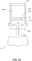
- Figs. 2b-2c schematically depict two further embodiments of the lighting device 100, with the latter having the light source 10 arranged external from the chamber.
- the wavelength converter 300 is arranged at a non-zero distance from the light source 10, especially from its light emitting surface.
- the distance is indicated with reference d2 and may e.g. be in the range of 0.1-100 mm, such as 1-100 mm, like 2-20 mm.
- reference 211 in Fig. 2c refers to a radiation transmissive window.
- the entire wall 201 is radiation transmissive.
- Reference 240 refers to a material that releases water.
- the configuration of the water releasing material 240 in Fig. 2c as layer is only an example of the many options such material may be arranged.
- silica coated QDs peak maximum of ⁇ 610 nm at room temperature
- YAG:Ce powder was added to the QD-silicone mixture, and this blend was dispensed into LED packages, after which the phosphor-silicone blend was cured for 2 hours at 150C.
- the concentration of QDs and YAG:Ce material was tuned in order to achieve a color temperature of 2700K-3000K (close to or on the black body line), and high CRI (80, 85, 90, or higher).
- u' is the appropriate parameter to follow the QD emission over time because the QDs emit at around 610-620 nm. A shift in u' larger than 0.007 over the LED lifespan is generally considered to be not acceptable.
- Upon sealing (so without turning on/off the LED), it is observed that the LEDs enclosed under dry conditions (0%, and 1% RH) show a significant drop in u' (i.e. loss in QD emission).
- the LED sealed under 10% RH shows a moderate drop in u', and the LED in 80% RH shows an increase in u', similar to the LED that was not sealed (i.e. ambient conditions).
- a control LED without QDs which was also sealed at 80% RH did not show any changes upon sealing.
- the data show that 0% is not wanted and 1% is less desirable, 80% is the same as open, and that in the order of about 5-10% RH is a critical filling value for these lamps.
- the lower value may be 5 % RH but this may depend upon the lamp type and pressure.
- the value of at least 1% is chosen, even more especially at least 5%, such as at least 10%.
- Silica powder and/or other powders like titania may be provided as coating at the internal surface of at least part of the wall(s) of the chamber, especially the light transmissive part, to provide a frosted appearance.
- red emitting quantum dots consisting of a CdSe core and a ZnS shell were silica coated using the reverse micelle method as adapted by Koole et al. (see above). They were incorporated into an optical quality silicone and dropcasted onto a glass plate. The silicone was cured at 150°C for two hours. The optical properties of the quantum dot containing film were tested at 450 nm light of an intensity of 10 W/cm 2 at a temperature of 100°C, detecting the intensity of the emitted light using an integrating sphere coupled to a spectrophotometer.
Landscapes
- Engineering & Computer Science (AREA)
- General Engineering & Computer Science (AREA)
- Physics & Mathematics (AREA)
- Spectroscopy & Molecular Physics (AREA)
- Microelectronics & Electronic Packaging (AREA)
- Optics & Photonics (AREA)
- Led Device Packages (AREA)
- Luminescent Compositions (AREA)
- Optical Filters (AREA)
- Non-Portable Lighting Devices Or Systems Thereof (AREA)
- Planar Illumination Modules (AREA)
Claims (11)
- Beleuchtungsvorrichtung (100), umfassend (i) eine geschlossene Kammer (200) mit einem lichtdurchlässigen Fenster (210) und (ii) eine Lichtquelle (10), die dafür gestaltet ist, Lichtquellenstrahlung (11) in die Kammer (200) bereitzustellen, wobei die Kammer (200) ferner einen Wellenlängenwandler (300) umschließt, der dafür gestaltet ist, zumindest einen Teil der Lichtquellenstrahlung (11) in Wellenlängenwandlerlicht (301) umzuwandeln, wobei das lichtdurchlässige Fenster (210) für das Wellenlängenwandlerlicht (301) durchlässig ist, wobei der Wellenlängenwandler (300) lumineszierende Quantenpunkte (30) umfasst, die nach Anregung durch zumindest einen Teil der Lichtquellenstrahlung (11) mindestens einen Teil des Wellenlängenwandlerlichts (301) erzeugen, und wobei die geschlossene Kammer (200) ein Füllgas (40) umfasst, das Heliumgas und/oder Wasserstoffgas und/oder Stickstoffgas und/oder Sauerstoffgas umfasst, dadurch gekennzeichnet, dass das Füllgas bei 19 °C eine relative Feuchte von mindestens 5 % aufweist.
- Beleuchtungsvorrichtung (100) nach Anspruch 1, wobei der Wellenlängenwandler (300) eine Siloxanmatrix (310) umfasst, in welche die lumineszierenden Quantenpunkte (30) eingebettet sind.
- Beleuchtungsvorrichtung (100) nach einem der vorhergehenden Ansprüche, wobei die lumineszierenden Quantenpunkte (30) eine anorganische Beschichtung (45) umfassen.
- Beleuchtungsvorrichtung (100) nach einem der vorhergehenden Ansprüche, wobei das Füllgas Helium umfasst.
- Beleuchtungsvorrichtung (100) nach einem der vorhergehenden Ansprüche, wobei mindestens 80 % des Füllgases (40) aus He bestehen, wobei das Füllgas ferner bei 19 °C eine relative Feuchte von mindestens 5 % aufweist und wobei die Kammer bei 19 °C kein flüssiges Wasser umfasst.
- Beleuchtungsvorrichtung (100) nach einem der vorhergehenden Ansprüche, wobei mindestens 95 % des Füllgases (40) aus He und O2 bestehen und wobei das Gas maximal 25 % Sauerstoff umfasst.
- Beleuchtungsvorrichtung (100) nach einem der vorhergehenden Ansprüche, wobei die geschlossene Kammer (200) ein leuchtkolbenförmiges lichtdurchlässiges Fenster (210) umfasst.
- Beleuchtungsvorrichtung (100) nach einem der vorhergehenden Ansprüche, wobei die Lichtquelle (10) dafür gestaltet ist, blaue Lichtquellenstrahlung (11) bereitzustellen, und wobei der Wellenlängenwandler (300) dafür gestaltet ist, zumindest einen Teil der Lichtquellenstrahlung (11) in Wellenlängenwandlerlicht (301) mit einer grünen Komponente und/oder einer gelben Komponente und/oder einer orangefarbenen Komponente und/oder einer roten Komponente umzuwandeln.
- Beleuchtungsvorrichtung (100) nach einem der vorhergehenden Ansprüche, wobei die Lichtquelle (10) eine Festkörper-Lichtquelle umfasst.
- Beleuchtungsvorrichtung (100) nach einem der vorhergehenden Ansprüche, ferner einen Wärmeableiter (117) in thermischem Kontakt mit dem durchlässigen Fenster (210) und/oder der Lichtquelle (10) und/oder dem Wellenlängenwandler (300) umfassend.
- Verfahren zur Herstellung einer Beleuchtungsvorrichtung, die eine geschlossene Kammer (200) mit einem lichtdurchlässigen Fenster (210) und eine Lichtquelle (10) umfasst, die dafür gestaltet ist, Lichtquellenstrahlung (11) in die Kammer (200) bereitzustellen, wobei die Kammer (200) ferner einen Wellenlängenwandler (300) umschließt, der dafür gestaltet ist, zumindest einen Teil der Lichtquellenstrahlung (11) in Wellenlängenwandlerlicht (301) umzuwandeln, wobei das lichtdurchlässige Fenster (210) für das Wellenlängenwandlerlicht (301) durchlässig ist, wobei der Wellenlängenwandler (300) lumineszierende Quantenpunkte (30) umfasst, die nach Anregung durch zumindest einen Teil der Lichtquellenstrahlung (11) mindestens einen Teil des Wellenlängenwandlerlichts (301) erzeugen, und wobei die geschlossene Kammer (200) ein Füllgas (40) umfasst, das Heliumgas und/oder Wasserstoffgas und/oder Stickstoffgas und/oder Sauerstoffgas umfasst, wobei das Füllgas bei 19 °C eine relative Feuchte von mindestens 1 % aufweist, wobei das Verfahren das Zusammenfügen der Kammer (200) mit einem lichtdurchlässigen Fenster (210), der Lichtquelle (10) und dem Wellenlängenwandler (300) in einem Zusammenfügeverfahren umfasst, wobei das Füllgas (40) und Wasser in die Kammer (200) bereitgestellt werden,
wobei das Füllgas (40) erzielt wird, nachdem ein Gasverschluss (207) für die Kammer (200) bereitgestellt wurde, und
wobei die Kammer (200) ferner ein Material (240) umfasst, das während zumindest eines Teils seiner Verwendungsdauer Wasser freisetzt.
Applications Claiming Priority (3)
| Application Number | Priority Date | Filing Date | Title |
|---|---|---|---|
| US201462057334P | 2014-09-30 | 2014-09-30 | |
| EP14189526 | 2014-10-20 | ||
| PCT/EP2015/071245 WO2016050517A1 (en) | 2014-09-30 | 2015-09-16 | Quantum dots in enclosed environment |
Publications (3)
| Publication Number | Publication Date |
|---|---|
| EP3201513A1 EP3201513A1 (de) | 2017-08-09 |
| EP3201513B1 true EP3201513B1 (de) | 2018-03-07 |
| EP3201513B8 EP3201513B8 (de) | 2018-08-29 |
Family
ID=51786811
Family Applications (1)
| Application Number | Title | Priority Date | Filing Date |
|---|---|---|---|
| EP15763357.9A Active EP3201513B8 (de) | 2014-09-30 | 2015-09-16 | Quantenpunkte in geschlossener umgebung |
Country Status (7)
| Country | Link |
|---|---|
| US (1) | US10156325B2 (de) |
| EP (1) | EP3201513B8 (de) |
| JP (1) | JP6748072B2 (de) |
| KR (1) | KR102362773B1 (de) |
| CN (1) | CN106716001B (de) |
| TW (1) | TWI662722B (de) |
| WO (1) | WO2016050517A1 (de) |
Families Citing this family (8)
| Publication number | Priority date | Publication date | Assignee | Title |
|---|---|---|---|---|
| KR102673595B1 (ko) * | 2017-02-14 | 2024-06-12 | 삼성전자주식회사 | Led 장치 및 그 제조 방법 |
| KR102601056B1 (ko) * | 2017-02-14 | 2023-11-10 | 삼성디스플레이 주식회사 | 양자점, 색변환 패널 및 이를 포함하는 표시 장치 |
| US10345688B2 (en) * | 2017-04-18 | 2019-07-09 | Unique Materials Co., Ltd. | Light emitting apparatus using composite material |
| CN110582667A (zh) * | 2017-05-11 | 2019-12-17 | 通用电气公司 | 玻璃led组件 |
| WO2019022194A1 (ja) * | 2017-07-28 | 2019-01-31 | 住友化学株式会社 | 組成物、フィルム、積層構造体、発光装置、及びディスプレイ |
| US11101403B1 (en) * | 2020-03-13 | 2021-08-24 | Shenzhen Xiangyou Technology Co., Ltd | Surface light source |
| JP7355724B2 (ja) * | 2020-12-07 | 2023-10-03 | 信越化学工業株式会社 | 量子ドットの表面処理方法及び表面処理装置 |
| US12498095B2 (en) | 2023-08-23 | 2025-12-16 | Autosystems, A Division Of Magna Exteriors Inc. | Vehicle lighting assembly with three-dimensional luminescent structure |
Family Cites Families (14)
| Publication number | Priority date | Publication date | Assignee | Title |
|---|---|---|---|---|
| US6322901B1 (en) | 1997-11-13 | 2001-11-27 | Massachusetts Institute Of Technology | Highly luminescent color-selective nano-crystalline materials |
| US20070267976A1 (en) * | 2003-05-05 | 2007-11-22 | Bohler Christopher L | Led-Based Light Bulb |
| JP2005333014A (ja) * | 2004-05-20 | 2005-12-02 | Koha Co Ltd | Ledランプ |
| JP2007165811A (ja) * | 2005-12-16 | 2007-06-28 | Nichia Chem Ind Ltd | 発光装置 |
| US8390193B2 (en) * | 2008-12-31 | 2013-03-05 | Intematix Corporation | Light emitting device with phosphor wavelength conversion |
| JP2013509714A (ja) | 2009-10-30 | 2013-03-14 | ナノシス・インク. | ナノ結晶を含む発光ダイオード(led)デバイス |
| JP5798722B2 (ja) * | 2010-06-25 | 2015-10-21 | シャープ株式会社 | 発光装置および照明装置 |
| JP2013545263A (ja) * | 2010-09-28 | 2013-12-19 | コーニンクレッカ フィリップス エヌ ヴェ | 発光装置 |
| CN103270136B (zh) * | 2010-12-21 | 2016-08-10 | 皇家飞利浦电子股份有限公司 | 具有包含聚合物的基体的照明设备 |
| US8425065B2 (en) * | 2010-12-30 | 2013-04-23 | Xicato, Inc. | LED-based illumination modules with thin color converting layers |
| US9365766B2 (en) * | 2011-10-13 | 2016-06-14 | Intematix Corporation | Wavelength conversion component having photo-luminescence material embedded into a hermetic material for remote wavelength conversion |
| US8757839B2 (en) * | 2012-04-13 | 2014-06-24 | Cree, Inc. | Gas cooled LED lamp |
| JP6360150B2 (ja) * | 2013-03-20 | 2018-07-18 | コーニンクレッカ フィリップス エヌ ヴェKoninklijke Philips N.V. | 多孔質粒子内の封止量子ドット |
| CN104061556A (zh) * | 2014-06-24 | 2014-09-24 | 厦门市东林电子有限公司 | 一种led灯中散热防光衰混合气体 |
-
2015
- 2015-09-16 US US15/512,434 patent/US10156325B2/en active Active
- 2015-09-16 WO PCT/EP2015/071245 patent/WO2016050517A1/en not_active Ceased
- 2015-09-16 EP EP15763357.9A patent/EP3201513B8/de active Active
- 2015-09-16 JP JP2017516651A patent/JP6748072B2/ja active Active
- 2015-09-16 KR KR1020177011908A patent/KR102362773B1/ko active Active
- 2015-09-16 CN CN201580053295.1A patent/CN106716001B/zh active Active
- 2015-09-30 TW TW104132244A patent/TWI662722B/zh active
Also Published As
| Publication number | Publication date |
|---|---|
| KR20170065617A (ko) | 2017-06-13 |
| JP6748072B2 (ja) | 2020-08-26 |
| CN106716001B (zh) | 2019-12-13 |
| EP3201513B8 (de) | 2018-08-29 |
| TWI662722B (zh) | 2019-06-11 |
| JP2017538244A (ja) | 2017-12-21 |
| US10156325B2 (en) | 2018-12-18 |
| KR102362773B1 (ko) | 2022-02-15 |
| CN106716001A (zh) | 2017-05-24 |
| TW201622181A (zh) | 2016-06-16 |
| WO2016050517A1 (en) | 2016-04-07 |
| US20170276300A1 (en) | 2017-09-28 |
| EP3201513A1 (de) | 2017-08-09 |
Similar Documents
| Publication | Publication Date | Title |
|---|---|---|
| EP3201513B1 (de) | Quantenpunkte in geschlossener umgebung | |
| US10158052B2 (en) | LED based device with wide color gamut | |
| KR102577454B1 (ko) | 하이브리드 코팅을 갖는 인광체 및 제조 방법 | |
| US9825241B2 (en) | Green emitting phosphors combined with broad band organic red emitters with a sharp near IR cut off | |
| EP2912370B1 (de) | Mit farbdarstellungsindex abstimmbare lampe und leuchte | |
| EP3174952B1 (de) | Lumineszierendes material enthaltend siliciumdioxidbeschichtete quantenpunkte, ein verfahren zu dessen herstellung, wellenlängenkonverter und beleuchtungsvorrichtung | |
| RU2616080C2 (ru) | Источник света с квантовыми точками | |
| JP2013033916A (ja) | 発光装置及びその製造方法 | |
| US10615316B2 (en) | Manganese-doped phosphor materials for high power density applications |
Legal Events
| Date | Code | Title | Description |
|---|---|---|---|
| STAA | Information on the status of an ep patent application or granted ep patent |
Free format text: STATUS: THE INTERNATIONAL PUBLICATION HAS BEEN MADE |
|
| PUAI | Public reference made under article 153(3) epc to a published international application that has entered the european phase |
Free format text: ORIGINAL CODE: 0009012 |
|
| STAA | Information on the status of an ep patent application or granted ep patent |
Free format text: STATUS: REQUEST FOR EXAMINATION WAS MADE |
|
| 17P | Request for examination filed |
Effective date: 20170502 |
|
| AK | Designated contracting states |
Kind code of ref document: A1 Designated state(s): AL AT BE BG CH CY CZ DE DK EE ES FI FR GB GR HR HU IE IS IT LI LT LU LV MC MK MT NL NO PL PT RO RS SE SI SK SM TR |
|
| AX | Request for extension of the european patent |
Extension state: BA ME |
|
| REG | Reference to a national code |
Ref country code: DE Ref legal event code: R079 Ref document number: 602015008602 Country of ref document: DE Free format text: PREVIOUS MAIN CLASS: F21K0099000000 Ipc: F21K0009232000 |
|
| RIC1 | Information provided on ipc code assigned before grant |
Ipc: F21K 9/64 20160101ALI20171013BHEP Ipc: F21Y 115/10 20160101ALN20171013BHEP Ipc: F21K 9/232 20160101AFI20171013BHEP |
|
| GRAP | Despatch of communication of intention to grant a patent |
Free format text: ORIGINAL CODE: EPIDOSNIGR1 |
|
| STAA | Information on the status of an ep patent application or granted ep patent |
Free format text: STATUS: GRANT OF PATENT IS INTENDED |
|
| DAV | Request for validation of the european patent (deleted) | ||
| DAX | Request for extension of the european patent (deleted) | ||
| INTG | Intention to grant announced |
Effective date: 20171204 |
|
| GRAS | Grant fee paid |
Free format text: ORIGINAL CODE: EPIDOSNIGR3 |
|
| GRAA | (expected) grant |
Free format text: ORIGINAL CODE: 0009210 |
|
| STAA | Information on the status of an ep patent application or granted ep patent |
Free format text: STATUS: THE PATENT HAS BEEN GRANTED |
|
| AK | Designated contracting states |
Kind code of ref document: B1 Designated state(s): AL AT BE BG CH CY CZ DE DK EE ES FI FR GB GR HR HU IE IS IT LI LT LU LV MC MK MT NL NO PL PT RO RS SE SI SK SM TR |
|
| REG | Reference to a national code |
Ref country code: GB Ref legal event code: FG4D |
|
| REG | Reference to a national code |
Ref country code: CH Ref legal event code: EP Ref country code: AT Ref legal event code: REF Ref document number: 976942 Country of ref document: AT Kind code of ref document: T Effective date: 20180315 |
|
| REG | Reference to a national code |
Ref country code: IE Ref legal event code: FG4D |
|
| REG | Reference to a national code |
Ref country code: DE Ref legal event code: R096 Ref document number: 602015008602 Country of ref document: DE |
|
| REG | Reference to a national code |
Ref country code: NL Ref legal event code: MP Effective date: 20180307 |
|
| REG | Reference to a national code |
Ref country code: LT Ref legal event code: MG4D |
|
| PG25 | Lapsed in a contracting state [announced via postgrant information from national office to epo] |
Ref country code: CY Free format text: LAPSE BECAUSE OF FAILURE TO SUBMIT A TRANSLATION OF THE DESCRIPTION OR TO PAY THE FEE WITHIN THE PRESCRIBED TIME-LIMIT Effective date: 20180307 Ref country code: LT Free format text: LAPSE BECAUSE OF FAILURE TO SUBMIT A TRANSLATION OF THE DESCRIPTION OR TO PAY THE FEE WITHIN THE PRESCRIBED TIME-LIMIT Effective date: 20180307 Ref country code: NO Free format text: LAPSE BECAUSE OF FAILURE TO SUBMIT A TRANSLATION OF THE DESCRIPTION OR TO PAY THE FEE WITHIN THE PRESCRIBED TIME-LIMIT Effective date: 20180607 Ref country code: HR Free format text: LAPSE BECAUSE OF FAILURE TO SUBMIT A TRANSLATION OF THE DESCRIPTION OR TO PAY THE FEE WITHIN THE PRESCRIBED TIME-LIMIT Effective date: 20180307 Ref country code: ES Free format text: LAPSE BECAUSE OF FAILURE TO SUBMIT A TRANSLATION OF THE DESCRIPTION OR TO PAY THE FEE WITHIN THE PRESCRIBED TIME-LIMIT Effective date: 20180307 Ref country code: FI Free format text: LAPSE BECAUSE OF FAILURE TO SUBMIT A TRANSLATION OF THE DESCRIPTION OR TO PAY THE FEE WITHIN THE PRESCRIBED TIME-LIMIT Effective date: 20180307 |
|
| RAP2 | Party data changed (patent owner data changed or rights of a patent transferred) |
Owner name: LUMILEDS HOLDING B.V. |
|
| REG | Reference to a national code |
Ref country code: AT Ref legal event code: MK05 Ref document number: 976942 Country of ref document: AT Kind code of ref document: T Effective date: 20180307 Ref country code: CH Ref legal event code: PK Free format text: BERICHTIGUNG B8 |
|
| PG25 | Lapsed in a contracting state [announced via postgrant information from national office to epo] |
Ref country code: RS Free format text: LAPSE BECAUSE OF FAILURE TO SUBMIT A TRANSLATION OF THE DESCRIPTION OR TO PAY THE FEE WITHIN THE PRESCRIBED TIME-LIMIT Effective date: 20180307 Ref country code: GR Free format text: LAPSE BECAUSE OF FAILURE TO SUBMIT A TRANSLATION OF THE DESCRIPTION OR TO PAY THE FEE WITHIN THE PRESCRIBED TIME-LIMIT Effective date: 20180608 Ref country code: BG Free format text: LAPSE BECAUSE OF FAILURE TO SUBMIT A TRANSLATION OF THE DESCRIPTION OR TO PAY THE FEE WITHIN THE PRESCRIBED TIME-LIMIT Effective date: 20180607 Ref country code: LV Free format text: LAPSE BECAUSE OF FAILURE TO SUBMIT A TRANSLATION OF THE DESCRIPTION OR TO PAY THE FEE WITHIN THE PRESCRIBED TIME-LIMIT Effective date: 20180307 Ref country code: SE Free format text: LAPSE BECAUSE OF FAILURE TO SUBMIT A TRANSLATION OF THE DESCRIPTION OR TO PAY THE FEE WITHIN THE PRESCRIBED TIME-LIMIT Effective date: 20180307 |
|
| REG | Reference to a national code |
Ref country code: FR Ref legal event code: PLFP Year of fee payment: 4 |
|
| PG25 | Lapsed in a contracting state [announced via postgrant information from national office to epo] |
Ref country code: AL Free format text: LAPSE BECAUSE OF FAILURE TO SUBMIT A TRANSLATION OF THE DESCRIPTION OR TO PAY THE FEE WITHIN THE PRESCRIBED TIME-LIMIT Effective date: 20180307 Ref country code: NL Free format text: LAPSE BECAUSE OF FAILURE TO SUBMIT A TRANSLATION OF THE DESCRIPTION OR TO PAY THE FEE WITHIN THE PRESCRIBED TIME-LIMIT Effective date: 20180307 Ref country code: PL Free format text: LAPSE BECAUSE OF FAILURE TO SUBMIT A TRANSLATION OF THE DESCRIPTION OR TO PAY THE FEE WITHIN THE PRESCRIBED TIME-LIMIT Effective date: 20180307 Ref country code: RO Free format text: LAPSE BECAUSE OF FAILURE TO SUBMIT A TRANSLATION OF THE DESCRIPTION OR TO PAY THE FEE WITHIN THE PRESCRIBED TIME-LIMIT Effective date: 20180307 Ref country code: IT Free format text: LAPSE BECAUSE OF FAILURE TO SUBMIT A TRANSLATION OF THE DESCRIPTION OR TO PAY THE FEE WITHIN THE PRESCRIBED TIME-LIMIT Effective date: 20180307 Ref country code: EE Free format text: LAPSE BECAUSE OF FAILURE TO SUBMIT A TRANSLATION OF THE DESCRIPTION OR TO PAY THE FEE WITHIN THE PRESCRIBED TIME-LIMIT Effective date: 20180307 |
|
| PG25 | Lapsed in a contracting state [announced via postgrant information from national office to epo] |
Ref country code: SK Free format text: LAPSE BECAUSE OF FAILURE TO SUBMIT A TRANSLATION OF THE DESCRIPTION OR TO PAY THE FEE WITHIN THE PRESCRIBED TIME-LIMIT Effective date: 20180307 Ref country code: CZ Free format text: LAPSE BECAUSE OF FAILURE TO SUBMIT A TRANSLATION OF THE DESCRIPTION OR TO PAY THE FEE WITHIN THE PRESCRIBED TIME-LIMIT Effective date: 20180307 Ref country code: SM Free format text: LAPSE BECAUSE OF FAILURE TO SUBMIT A TRANSLATION OF THE DESCRIPTION OR TO PAY THE FEE WITHIN THE PRESCRIBED TIME-LIMIT Effective date: 20180307 Ref country code: AT Free format text: LAPSE BECAUSE OF FAILURE TO SUBMIT A TRANSLATION OF THE DESCRIPTION OR TO PAY THE FEE WITHIN THE PRESCRIBED TIME-LIMIT Effective date: 20180307 |
|
| REG | Reference to a national code |
Ref country code: DE Ref legal event code: R097 Ref document number: 602015008602 Country of ref document: DE |
|
| PG25 | Lapsed in a contracting state [announced via postgrant information from national office to epo] |
Ref country code: PT Free format text: LAPSE BECAUSE OF FAILURE TO SUBMIT A TRANSLATION OF THE DESCRIPTION OR TO PAY THE FEE WITHIN THE PRESCRIBED TIME-LIMIT Effective date: 20180709 |
|
| PLBE | No opposition filed within time limit |
Free format text: ORIGINAL CODE: 0009261 |
|
| STAA | Information on the status of an ep patent application or granted ep patent |
Free format text: STATUS: NO OPPOSITION FILED WITHIN TIME LIMIT |
|
| PG25 | Lapsed in a contracting state [announced via postgrant information from national office to epo] |
Ref country code: DK Free format text: LAPSE BECAUSE OF FAILURE TO SUBMIT A TRANSLATION OF THE DESCRIPTION OR TO PAY THE FEE WITHIN THE PRESCRIBED TIME-LIMIT Effective date: 20180307 |
|
| 26N | No opposition filed |
Effective date: 20181210 |
|
| PG25 | Lapsed in a contracting state [announced via postgrant information from national office to epo] |
Ref country code: MC Free format text: LAPSE BECAUSE OF FAILURE TO SUBMIT A TRANSLATION OF THE DESCRIPTION OR TO PAY THE FEE WITHIN THE PRESCRIBED TIME-LIMIT Effective date: 20180307 |
|
| REG | Reference to a national code |
Ref country code: CH Ref legal event code: PL |
|
| REG | Reference to a national code |
Ref country code: BE Ref legal event code: MM Effective date: 20180930 |
|
| REG | Reference to a national code |
Ref country code: IE Ref legal event code: MM4A |
|
| PG25 | Lapsed in a contracting state [announced via postgrant information from national office to epo] |
Ref country code: LU Free format text: LAPSE BECAUSE OF NON-PAYMENT OF DUE FEES Effective date: 20180916 |
|
| PG25 | Lapsed in a contracting state [announced via postgrant information from national office to epo] |
Ref country code: IE Free format text: LAPSE BECAUSE OF NON-PAYMENT OF DUE FEES Effective date: 20180916 |
|
| PG25 | Lapsed in a contracting state [announced via postgrant information from national office to epo] |
Ref country code: CH Free format text: LAPSE BECAUSE OF NON-PAYMENT OF DUE FEES Effective date: 20180930 Ref country code: LI Free format text: LAPSE BECAUSE OF NON-PAYMENT OF DUE FEES Effective date: 20180930 Ref country code: BE Free format text: LAPSE BECAUSE OF NON-PAYMENT OF DUE FEES Effective date: 20180930 |
|
| PG25 | Lapsed in a contracting state [announced via postgrant information from national office to epo] |
Ref country code: MT Free format text: LAPSE BECAUSE OF NON-PAYMENT OF DUE FEES Effective date: 20180916 |
|
| PG25 | Lapsed in a contracting state [announced via postgrant information from national office to epo] |
Ref country code: TR Free format text: LAPSE BECAUSE OF FAILURE TO SUBMIT A TRANSLATION OF THE DESCRIPTION OR TO PAY THE FEE WITHIN THE PRESCRIBED TIME-LIMIT Effective date: 20180307 |
|
| PG25 | Lapsed in a contracting state [announced via postgrant information from national office to epo] |
Ref country code: HU Free format text: LAPSE BECAUSE OF FAILURE TO SUBMIT A TRANSLATION OF THE DESCRIPTION OR TO PAY THE FEE WITHIN THE PRESCRIBED TIME-LIMIT; INVALID AB INITIO Effective date: 20150916 Ref country code: MK Free format text: LAPSE BECAUSE OF NON-PAYMENT OF DUE FEES Effective date: 20180307 |
|
| PG25 | Lapsed in a contracting state [announced via postgrant information from national office to epo] |
Ref country code: IS Free format text: LAPSE BECAUSE OF FAILURE TO SUBMIT A TRANSLATION OF THE DESCRIPTION OR TO PAY THE FEE WITHIN THE PRESCRIBED TIME-LIMIT Effective date: 20180707 |
|
| PG25 | Lapsed in a contracting state [announced via postgrant information from national office to epo] |
Ref country code: SI Free format text: LAPSE BECAUSE OF NON-PAYMENT OF DUE FEES Effective date: 20180916 |
|
| P01 | Opt-out of the competence of the unified patent court (upc) registered |
Effective date: 20230530 |
|
| PGFP | Annual fee paid to national office [announced via postgrant information from national office to epo] |
Ref country code: DE Payment date: 20250926 Year of fee payment: 11 |
|
| PGFP | Annual fee paid to national office [announced via postgrant information from national office to epo] |
Ref country code: GB Payment date: 20250923 Year of fee payment: 11 |
|
| PGFP | Annual fee paid to national office [announced via postgrant information from national office to epo] |
Ref country code: FR Payment date: 20250925 Year of fee payment: 11 |