EP3201546B1 - Kältegerät mit auszugkasten - Google Patents
Kältegerät mit auszugkasten Download PDFInfo
- Publication number
- EP3201546B1 EP3201546B1 EP15763267.0A EP15763267A EP3201546B1 EP 3201546 B1 EP3201546 B1 EP 3201546B1 EP 15763267 A EP15763267 A EP 15763267A EP 3201546 B1 EP3201546 B1 EP 3201546B1
- Authority
- EP
- European Patent Office
- Prior art keywords
- drawer
- shelf
- refrigeration appliance
- appliance according
- side wall
- Prior art date
- Legal status (The legal status is an assumption and is not a legal conclusion. Google has not performed a legal analysis and makes no representation as to the accuracy of the status listed.)
- Active
Links
Images


Classifications
-
- F—MECHANICAL ENGINEERING; LIGHTING; HEATING; WEAPONS; BLASTING
- F25—REFRIGERATION OR COOLING; COMBINED HEATING AND REFRIGERATION SYSTEMS; HEAT PUMP SYSTEMS; MANUFACTURE OR STORAGE OF ICE; LIQUEFACTION SOLIDIFICATION OF GASES
- F25D—REFRIGERATORS; COLD ROOMS; ICE-BOXES; COOLING OR FREEZING APPARATUS NOT OTHERWISE PROVIDED FOR
- F25D25/00—Charging, supporting, and discharging the articles to be cooled
- F25D25/02—Charging, supporting, and discharging the articles to be cooled by shelves
- F25D25/024—Slidable shelves
- F25D25/025—Drawers
-
- F—MECHANICAL ENGINEERING; LIGHTING; HEATING; WEAPONS; BLASTING
- F25—REFRIGERATION OR COOLING; COMBINED HEATING AND REFRIGERATION SYSTEMS; HEAT PUMP SYSTEMS; MANUFACTURE OR STORAGE OF ICE; LIQUEFACTION SOLIDIFICATION OF GASES
- F25D—REFRIGERATORS; COLD ROOMS; ICE-BOXES; COOLING OR FREEZING APPARATUS NOT OTHERWISE PROVIDED FOR
- F25D17/00—Arrangements for circulating cooling fluids; Arrangements for circulating gas, e.g. air, within refrigerated spaces
- F25D17/04—Arrangements for circulating cooling fluids; Arrangements for circulating gas, e.g. air, within refrigerated spaces for circulating air, e.g. by convection
- F25D17/042—Air treating means within refrigerated spaces
- F25D17/045—Air flow control arrangements
-
- F—MECHANICAL ENGINEERING; LIGHTING; HEATING; WEAPONS; BLASTING
- F25—REFRIGERATION OR COOLING; COMBINED HEATING AND REFRIGERATION SYSTEMS; HEAT PUMP SYSTEMS; MANUFACTURE OR STORAGE OF ICE; LIQUEFACTION SOLIDIFICATION OF GASES
- F25D—REFRIGERATORS; COLD ROOMS; ICE-BOXES; COOLING OR FREEZING APPARATUS NOT OTHERWISE PROVIDED FOR
- F25D2300/00—Special arrangements or features for refrigerators; cold rooms; ice-boxes; Cooling or freezing apparatus not covered by any other subclass
-
- F—MECHANICAL ENGINEERING; LIGHTING; HEATING; WEAPONS; BLASTING
- F25—REFRIGERATION OR COOLING; COMBINED HEATING AND REFRIGERATION SYSTEMS; HEAT PUMP SYSTEMS; MANUFACTURE OR STORAGE OF ICE; LIQUEFACTION SOLIDIFICATION OF GASES
- F25D—REFRIGERATORS; COLD ROOMS; ICE-BOXES; COOLING OR FREEZING APPARATUS NOT OTHERWISE PROVIDED FOR
- F25D2317/00—Details or arrangements for circulating cooling fluids; Details or arrangements for circulating gas, e.g. air, within refrigerated spaces, not provided for in other groups of this subclass
- F25D2317/04—Treating air flowing to refrigeration compartments
- F25D2317/041—Treating air flowing to refrigeration compartments by purification
- F25D2317/0413—Treating air flowing to refrigeration compartments by purification by humidification
- F25D2317/04131—Control means therefor
-
- F—MECHANICAL ENGINEERING; LIGHTING; HEATING; WEAPONS; BLASTING
- F25—REFRIGERATION OR COOLING; COMBINED HEATING AND REFRIGERATION SYSTEMS; HEAT PUMP SYSTEMS; MANUFACTURE OR STORAGE OF ICE; LIQUEFACTION SOLIDIFICATION OF GASES
- F25D—REFRIGERATORS; COLD ROOMS; ICE-BOXES; COOLING OR FREEZING APPARATUS NOT OTHERWISE PROVIDED FOR
- F25D2325/00—Charging, supporting or discharging the articles to be cooled, not provided for in other groups of this subclass
- F25D2325/021—Shelves with several possible configurations
-
- F—MECHANICAL ENGINEERING; LIGHTING; HEATING; WEAPONS; BLASTING
- F25—REFRIGERATION OR COOLING; COMBINED HEATING AND REFRIGERATION SYSTEMS; HEAT PUMP SYSTEMS; MANUFACTURE OR STORAGE OF ICE; LIQUEFACTION SOLIDIFICATION OF GASES
- F25D—REFRIGERATORS; COLD ROOMS; ICE-BOXES; COOLING OR FREEZING APPARATUS NOT OTHERWISE PROVIDED FOR
- F25D2325/00—Charging, supporting or discharging the articles to be cooled, not provided for in other groups of this subclass
- F25D2325/022—Shelves made of glass or ceramic
-
- F—MECHANICAL ENGINEERING; LIGHTING; HEATING; WEAPONS; BLASTING
- F25—REFRIGERATION OR COOLING; COMBINED HEATING AND REFRIGERATION SYSTEMS; HEAT PUMP SYSTEMS; MANUFACTURE OR STORAGE OF ICE; LIQUEFACTION SOLIDIFICATION OF GASES
- F25D—REFRIGERATORS; COLD ROOMS; ICE-BOXES; COOLING OR FREEZING APPARATUS NOT OTHERWISE PROVIDED FOR
- F25D2500/00—Problems to be solved
Definitions
- the present invention relates to a refrigeration appliance, in particular a domestic refrigeration appliance, which is particularly suitable for storing refrigerated goods that are sensitive to drying out.
- Fresh foods such as fruit, vegetables, salads or fresh herbs release moisture into their surroundings until a balance has been established between them and the surrounding air.
- Moisture that such food releases into the air in a storage chamber of a refrigeration device usually condenses after a short time on an evaporator that cools the storage chamber, so that the air humidity never reaches a saturation state. Therefore, the food constantly emits moisture, quickly dries up and becomes unsightly.
- WO 2013 186 128 A1 a household refrigeration appliance is known in which a cover is hung from a shelf dividing the storage space and rests tightly on a pull-out drawer in the pushed-in position. A user can adjust the strength of the air exchange between the interior of the pull-out drawer and the surrounding storage space via closable openings in the cover.
- a refrigeration device which has mesh baskets which can be pushed into the inner container and end in the height direction below a partition wall and at a distance therefrom.
- a refrigeration device with a container which has an interior climate control element.
- a container for food is known. This has a shell and a cover.
- WO 2010/02941 A1 discloses a refrigerator with a shell.
- the shell 3 is covered with an insert and a hood.
- the insert 5 is arranged between the hood 4 and the shell 3 .
- the object of the present invention is to provide such a structure which overcomes or reduces the disadvantages of the prior art.
- the object is achieved by using a refrigeration appliance with a storage space delimited by a body and a door, the storage space being divided into an upper and a lower compartment by a shelf and a pull-out drawer being accommodated in the lower compartment, in one into the lower compartment pushed-in stop position of the pull-out drawer a front wall of the pull-out drawer on a front edge of Shelf abuts, the shelf has a passage, and a closure element between a passage blocking position and a passage on at least a part of its cross-section releasing position is movable.
- attachment wall elements are detachably mounted on the side walls of the drawer. Instead of the top wall elements that move when the pull-out drawer is pulled out, side wall elements that are hung from the shelf can also be provided, which seal against the side walls of the pull-out drawer when it is in the pushed-in stop position.
- the attachment of the passage in the shelf makes a cover for the pull-out drawer as a component separate from the shelf superfluous.
- the passage is preferably arranged adjacent to the front edge of the shelf.
- the passage is preferably recessed from the frame.
- a slide which can be moved in the plane of the passage is preferably provided as a closing element which does not impede the other use of the shelf.
- Such a slide can be composed of two elements, one of which forms an upper side wall and the other a lower side wall of a groove in which the plate or a web of the frame engages, in order to control the displacement movement of the slide between the position blocking the passage and to lead the releasing position.
- the frame can have a web provided with openings, the openings of which cover the part of the cross section of the forming a passage, and which faces an edge of the plate, so that the slider is slidable between the passages of the web blocking position and an unblocking position in which parts of the slider engage the plate.
- the side wall elements are preferably connected to one another via a rear wall element.
- the rear wall element can be used to fix the side wall elements in relation to one another in order to ensure that in the pushed-in stop position both seal at the same time on the upper edges of the side walls; it can also perform a sealing function itself between a rear wall of the pull-out drawer and the shelf.
- the upper edges of the side walls of the pull-out drawer and optionally also the rear wall form sealing surfaces which rest against the suspended side and/or rear wall elements in the pushed-in stop position.
- the side walls and optionally the rear wall of the pull-out drawer are reinforced by webs angled along their upper edges, the upper sides of these webs in particular can serve as sealing surfaces.
- the side wall elements can be suspended vertically from the shelf with play in order to be able to compensate for any manufacturing tolerances.
- the side wall elements can then each have a shelf facing flange on an upper edge, which, by forming a narrow gap together with the shelf, the air exchange between the interior of the The pull-out drawer and the surrounding storage space cannot be completely prevented, but can at least severely limit it.
- the pull-out drawer can have a height-profiled base plate, at the lowest points of which condensation can collect, while higher points in between protect the refrigerated goods and keep them away from condensation.
- Local deepest points of the base plate are preferably adjacent to the walls of the pull-out drawer, on the one hand because such points are more difficult for the refrigerated goods to reach the closer they are to the walls, on the other hand because the condensation water is mainly on the walls of the Pull-out box forms.
- FIG. 1 shows a schematic section through a domestic refrigeration appliance with a body 1 and a door 2 surrounding a refrigerated storage space 3 .
- a shelf 4 divides the storage space 3 into an upper compartment 5 and a lower compartment 6.
- An evaporator chamber 7 is in direct connection with the lower compartment 6 via a duct 8, so that by intensively supplying cold air from the evaporator chamber 7 in the lower compartment 6 a lower temperature can be maintained than in the upper compartment 5.
- a pull-out drawer 9 is housed in the lower compartment 6 . Gaps 10 between the pull-out drawer 9 and the walls of the compartment 6 allow cold air to circulate freely around the pull-out drawer 9.
- the pull-out drawer 9 has a front wall 11 which rises above the side walls 12 and rear wall 13 and, in the shown pushed-in stop position of the pull-out drawer 9, closely touches a front edge of the shelf 4.
- the side walls 12 have upper edges 14 sloping down towards the rear wall 13. Attachment wall elements 15 mounted on these upper edges extend directly under the shelf 4.
- FIG. 2 shows the shelf 4 in a perspective view. It includes a plate 16 made of safety glass, which is surrounded by a molded frame 17 made of plastic all around. A bordering in the front edge of the plate 16 front profile 18 is wider than side profiles 19 and a rear profile 20 of the frame and provides space for a passage 21, which in the representation of the 2 is closed by a slide 22 movable in depth direction.
- the slide 22 is composed of an upper and a lower element 23, 24 together.
- Base plates 25, 26 of the elements 23, 24 are kept at a distance in a central region by spacers 27, so that a circumferential groove 28 is formed along their edges.
- the elements 23, 24 are fixed to one another by latching hooks 29 which project from one of the base plates 25, 26 and engage in slots 30 of the other base plate.
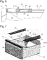
- FIG. 4 shows the slider 22 in the passage 21 closing position partly in a perspective view, partly in section.
- a web 31 of the front frame profile 18 and the front edge of the plate 16 engage in the groove 28 of the slide 22 on opposite sides.
- the plate 16 does not extend to a bottom of the groove 28, so that the slide 22, guided by a one on a narrow side of the slide 22 engaging in the groove 28, in 4 Web 32 of the profile 18 shown in dashed lines, from the position of 4 into a figure 5 shown position, in which the web 31 is largely exposed and an exchange of air between the upper compartment 5 and the interior of the pull-out drawer 9 arranged above the shelf is possible via openings 33 in the pull-out drawer 31, so that moisture can escape from the pull-out drawer 9 .
- the extent of the air exchange is controllable by a user by setting a position of the slide 22 between the two extreme positions of the Figures 4 and 5 selects, in which the openings 33 are more or less strongly hidden.
- a seal can be provided between the front edge of the shelf 4 and the front wall 11 of the pull-out drawer 9 in order to minimize an exchange of air that cannot be controlled by the user between the interior of the pull-out drawer 9 and its surroundings.
- this seal may be formed as a flexible lip 34 on the front edge of shelf 4 which is crimped into contact with the rear of front wall 11; alternatively, such a seal could also be attached to the back of the front wall 11 .
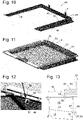
- a base part 35 molded in one piece from plastic forms a bottom plate 36, the side walls 12 and the rear wall 13 of the pull-out drawer 9.
- the walls 12, 13 are reinforced by webs 38 protruding outwards.
- the front wall 11 made of transparent plastic is snapped onto the base part 35 .
- the bottom plate 36 which is partially visible through the front wall 11, has a height profile in the form of a ribbed central plateau 40, surrounded by a ditch 39 which extends to the foot of the walls 11, 12, 13. Condensation water can collect in the ditch 39 on the walls, so that chilled goods lying on the ribs of the central plateau are protected from moisture penetration.
- the side walls 12 reach their greatest height immediately at their front end; over a large part of their length they run a few centimeters lower, at a considerable distance from the shelf 4, so that they do not prevent an intensive exchange of air between the pull-out drawer 9 and its surroundings. If refrigerated goods that are sensitive to drying out are to be accommodated in the pull-out drawer 9 , it makes sense to close these passages using the attachment wall elements 15 .
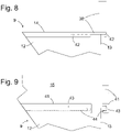
- the attachment wall elements 15 are plastic plates which are shaped to complement the shape of the upper edges 14, 37 of the side and rear walls 12, 13 and are provided with hooks 41 on their lower edges for latching on the webs 38 of the walls 12, 13.
- the webs 38 are each provided with downwardly projecting ribs 42 along part of their length.
- FIG. 9 shows in a too 8 analogous view of the top wall element 15 mounted on the drawer 9.
- the hooks 41 with which the top wall element 15 is clamped to the side and rear walls 12, 37, extend along the edges 14, 38 of the walls 12, 37 in each case over one length of a few centimeters and are elastically deformable thanks to a longitudinal slot 43, so that a locking lug 44 formed on a part of the hook 41 lying below the longitudinal slot 43 can be elastically deflected in contact with the rib 42 and, as in Fig 9 shown, can engage behind the rib 42 in order to fix the attachment wall element 15 in a form-fitting manner.
- the sealing frame includes two side wall elements 46, the lower edges of which are like those of the attachment wall elements 40 of 7 are shaped complementarily to the course of the upper edges 14 of the side walls 12 .
- the side wall elements 46 are connected to one another by a rear wall element 47.
- the rear wall 37 of the pull-out drawer 9 in this embodiment lacks the one shown in FIG 7 shown, over the rear ends of the side walls 12 towering area 48, instead the upper edge of the rear wall 13 runs horizontally between the corners.
- Flanges 49 projecting horizontally outwards are formed on the lower edges of the side wall and rear wall elements 46, 47, and flanges 50 project horizontally inwards along their upper edges.
- Hooks 51 project along the upper edge of the rear wall element 47, which, as in FIG 11 shown, are provided in order to encompass a rib 52 rising up on the rear profile 20 of the shelf 4 and thus to anchor the sealing frame 45 hanging on the shelf 4 .
- the side wall elements 46 Adjacent to their front ends, the side wall elements 46 each have a 12 pin 53 shown in an enlarged view, which engages with play in a tab 54 projecting downwards from one of its lateral profiles 19 .
- the engagement of the hooks 51 on the rib 52 of the shelf 4 also has slight play in the vertical direction, so that when the pull-out drawer 9 is pushed in, the upper edges 14 of the side walls 12 hit the flanges 49 of the sealing frame 45 before the stop position is reached ,
- the sealing frame 45 can deviate upwards.
- a gap 55 must be open between the sealing frame 45 and the shelf 4, which gap 55 must have when the pull-out drawer 9 is in the stop position is normally narrowed by raising the sealing frame 45, but will not be completely closed.
- the flanges 50 on the upper side of the sealing frame 45 considerably lengthen the path that air has to travel in this gap 55 in order to switch between the interior of the pull-out drawer 9 and its surroundings, and the exchange of air accordingly restricted by the gap 55 to such an extent that the climate in the pull-out drawer 9 can be controlled via the position of the slide 22 .
Landscapes
- Engineering & Computer Science (AREA)
- Chemical & Material Sciences (AREA)
- Combustion & Propulsion (AREA)
- Physics & Mathematics (AREA)
- Mechanical Engineering (AREA)
- Thermal Sciences (AREA)
- General Engineering & Computer Science (AREA)
- Drawers Of Furniture (AREA)
- Devices That Are Associated With Refrigeration Equipment (AREA)
- Cold Air Circulating Systems And Constructional Details In Refrigerators (AREA)
Applications Claiming Priority (2)
| Application Number | Priority Date | Filing Date | Title |
|---|---|---|---|
| DE102014219664.7A DE102014219664A1 (de) | 2014-09-29 | 2014-09-29 | Kältegerät mit Auszugkasten |
| PCT/EP2015/070320 WO2016050449A1 (de) | 2014-09-29 | 2015-09-07 | Kältegerät mit auszugkasten |
Publications (2)
| Publication Number | Publication Date |
|---|---|
| EP3201546A1 EP3201546A1 (de) | 2017-08-09 |
| EP3201546B1 true EP3201546B1 (de) | 2022-07-20 |
Family
ID=54106337
Family Applications (1)
| Application Number | Title | Priority Date | Filing Date |
|---|---|---|---|
| EP15763267.0A Active EP3201546B1 (de) | 2014-09-29 | 2015-09-07 | Kältegerät mit auszugkasten |
Country Status (7)
| Country | Link |
|---|---|
| US (2) | US20170276425A1 (pl) |
| EP (1) | EP3201546B1 (pl) |
| CN (1) | CN107076505B (pl) |
| DE (1) | DE102014219664A1 (pl) |
| PL (1) | PL3201546T3 (pl) |
| RU (1) | RU2656418C1 (pl) |
| WO (1) | WO2016050449A1 (pl) |
Cited By (1)
| Publication number | Priority date | Publication date | Assignee | Title |
|---|---|---|---|---|
| EP4715293A1 (de) * | 2024-09-05 | 2026-03-25 | BSH Hausgeräte GmbH | Trägereinrichtung mit spezifisch elastisch aufgeschnapptem adapterteil, sowie verfahren |
Families Citing this family (16)
| Publication number | Priority date | Publication date | Assignee | Title |
|---|---|---|---|---|
| US10139152B2 (en) * | 2013-10-03 | 2018-11-27 | Arcelik Anonim Sirketi | Refrigerator comprising a drawer |
| US9593879B2 (en) | 2015-03-17 | 2017-03-14 | Whirlpool Corporation | U-shaped tuck shelf |
| USD810493S1 (en) * | 2016-02-25 | 2018-02-20 | Dometic Sweden Ab | Cooktop cover |
| US10281197B2 (en) | 2016-10-11 | 2019-05-07 | Whirlpool Corporation | Quick shelf adjustment mechanism for a refrigerating appliance |
| DE102016220304A1 (de) | 2016-10-18 | 2018-04-19 | BSH Hausgeräte GmbH | Kältegerät mit Frischeschale |
| US10677514B2 (en) | 2017-08-01 | 2020-06-09 | Whirlpool Corporation | Door bin with dual material and system lock |
| BR102017019233B1 (pt) | 2017-09-08 | 2022-10-18 | Whirlpool S.A. | Sistema de translação para prateleira de refrigerador |
| DE102017216189A1 (de) * | 2017-09-13 | 2019-03-14 | BSH Hausgeräte GmbH | Haushaltskältegerät mit spezifischer frontseitiger Absenkung eines Fachbodens |
| US10371436B2 (en) | 2017-11-08 | 2019-08-06 | Whirlpool Corporation | Bin assembly |
| BR112020017851B1 (pt) * | 2018-03-02 | 2023-01-10 | Electrolux Do Brasil S.A. | Cobertura para um recipiente de armazenamento de um refrigerador |
| US10551071B2 (en) | 2018-05-11 | 2020-02-04 | Whirlpool Corporation | Oven rack system with removable support elements |
| US11073329B2 (en) | 2018-10-31 | 2021-07-27 | Whirlpool Corporation | Refrigerator shelving frame with snap-in sliding insert |
| DE102019214591A1 (de) * | 2019-09-24 | 2021-03-25 | BSH Hausgeräte GmbH | Lebensmittel-Aufnahmebehälter mit Schale und spezifischen Deckel dazu, sowie Haushaltskältegerät |
| TR201914652A2 (tr) * | 2019-09-26 | 2021-04-21 | Bsh Ev Aletleri San Ve Tic As | Bi̇r soğutucu ci̇haz |
| CN112373764A (zh) * | 2020-11-03 | 2021-02-19 | 湖州清优包装材料有限公司 | 一种抽拉式包装盒的自动合盖装置 |
| US12152831B2 (en) | 2021-04-06 | 2024-11-26 | Electrolux Home Products, Inc. | Crisper assembly with slide out shelf |
Citations (4)
| Publication number | Priority date | Publication date | Assignee | Title |
|---|---|---|---|---|
| KR200146134Y1 (ko) * | 1996-12-20 | 1999-06-15 | 윤종용 | 냉장고의 야채실 습도조절장치 |
| CN200952864Y (zh) * | 2006-04-29 | 2007-09-26 | 海尔集团公司 | 可调湿度的保鲜果盒 |
| WO2010029041A1 (en) * | 2008-09-09 | 2010-03-18 | Arcelik Anonim Sirketi | A cooling device |
| DE102011078146A1 (de) * | 2011-06-27 | 2012-12-27 | BSH Bosch und Siemens Hausgeräte GmbH | Kühlgutschublade für ein kältegerät sowie kältegerät |
Family Cites Families (21)
| Publication number | Priority date | Publication date | Assignee | Title |
|---|---|---|---|---|
| KR200156044Y1 (ko) * | 1997-06-30 | 1999-09-01 | 전주범 | 냉장고용 야채박스의 습도조절레바구조 |
| US7490915B2 (en) * | 2003-03-12 | 2009-02-17 | Maytag Corporation | Locking divider for a refrigerator storage compartment |
| CA2492347A1 (en) * | 2004-01-16 | 2005-07-16 | Maytag Corporation | Versatile refrigerator crisper system |
| KR101010793B1 (ko) * | 2004-02-11 | 2011-01-25 | 엘지전자 주식회사 | 냉장고 본체 및 그 제조방법 |
| US20090199587A1 (en) * | 2005-04-04 | 2009-08-13 | Fisher & Paykel Appliances Limited | Humidity control lid |
| KR101233200B1 (ko) * | 2006-04-14 | 2013-02-15 | 엘지전자 주식회사 | 냉장고용 수납박스 출납구조 |
| KR20070109517A (ko) * | 2006-05-11 | 2007-11-15 | 삼성전자주식회사 | 냉장고 |
| KR100719252B1 (ko) * | 2006-07-03 | 2007-05-18 | 주식회사 대우일렉트로닉스 | 냉장고용 야채박스의 커버 조립체 및 습도조절노브를조립하기 위한 구조 |
| WO2009099441A1 (en) * | 2008-02-07 | 2009-08-13 | Kueny Matthew D | Refrigerating apparatus and method |
| US8979621B2 (en) * | 2007-06-05 | 2015-03-17 | Electrolux Home Products, Inc. | Storage systems |
| DE102007048575A1 (de) * | 2007-10-10 | 2009-04-16 | BSH Bosch und Siemens Hausgeräte GmbH | Kältegerät |
| KR101695808B1 (ko) * | 2009-07-22 | 2017-01-13 | 엘지전자 주식회사 | 냉장고 |
| DE102009029133A1 (de) | 2009-09-02 | 2011-03-03 | BSH Bosch und Siemens Hausgeräte GmbH | Kühlgutbehälter für ein Kältegerät |
| DE102009029141A1 (de) * | 2009-09-02 | 2011-03-03 | BSH Bosch und Siemens Hausgeräte GmbH | Kältegerät mit Gemüsefach |
| US9115927B2 (en) * | 2011-04-29 | 2015-08-25 | Electrolux Home Products, Inc. | Crisper drawers with rollers and ramp |
| CN102721252A (zh) * | 2012-05-29 | 2012-10-10 | 海信容声(广东)冰箱有限公司 | 一种冰箱用悬挂储物盒 |
| DE102012209938A1 (de) | 2012-06-13 | 2013-12-19 | BSH Bosch und Siemens Hausgeräte GmbH | Kältegerät |
| DE102012209937A1 (de) * | 2012-06-13 | 2013-12-19 | BSH Bosch und Siemens Hausgeräte GmbH | Kältegerät |
| CN103575046A (zh) * | 2012-07-31 | 2014-02-12 | 海尔集团公司 | 一种冰箱果蔬盒及包括该果蔬盒的冰箱 |
| KR102028022B1 (ko) * | 2013-04-05 | 2019-10-04 | 삼성전자주식회사 | 냉장고 |
| DE102013225541A1 (de) * | 2013-12-11 | 2015-06-11 | BSH Hausgeräte GmbH | Haushaltskältegerät mit einer feuchtigkeitsdicht abschließenden Kühlgutschublade |
-
2014
- 2014-09-29 DE DE102014219664.7A patent/DE102014219664A1/de active Pending
-
2015
- 2015-09-07 US US15/510,894 patent/US20170276425A1/en not_active Abandoned
- 2015-09-07 RU RU2017113068A patent/RU2656418C1/ru active
- 2015-09-07 WO PCT/EP2015/070320 patent/WO2016050449A1/de not_active Ceased
- 2015-09-07 PL PL15763267.0T patent/PL3201546T3/pl unknown
- 2015-09-07 EP EP15763267.0A patent/EP3201546B1/de active Active
- 2015-09-07 CN CN201580052643.3A patent/CN107076505B/zh active Active
-
2018
- 2018-10-26 US US16/171,691 patent/US10386114B2/en active Active
Patent Citations (4)
| Publication number | Priority date | Publication date | Assignee | Title |
|---|---|---|---|---|
| KR200146134Y1 (ko) * | 1996-12-20 | 1999-06-15 | 윤종용 | 냉장고의 야채실 습도조절장치 |
| CN200952864Y (zh) * | 2006-04-29 | 2007-09-26 | 海尔集团公司 | 可调湿度的保鲜果盒 |
| WO2010029041A1 (en) * | 2008-09-09 | 2010-03-18 | Arcelik Anonim Sirketi | A cooling device |
| DE102011078146A1 (de) * | 2011-06-27 | 2012-12-27 | BSH Bosch und Siemens Hausgeräte GmbH | Kühlgutschublade für ein kältegerät sowie kältegerät |
Cited By (1)
| Publication number | Priority date | Publication date | Assignee | Title |
|---|---|---|---|---|
| EP4715293A1 (de) * | 2024-09-05 | 2026-03-25 | BSH Hausgeräte GmbH | Trägereinrichtung mit spezifisch elastisch aufgeschnapptem adapterteil, sowie verfahren |
Also Published As
| Publication number | Publication date |
|---|---|
| CN107076505B (zh) | 2020-03-03 |
| DE102014219664A1 (de) | 2016-03-31 |
| EP3201546A1 (de) | 2017-08-09 |
| WO2016050449A1 (de) | 2016-04-07 |
| US20190063821A1 (en) | 2019-02-28 |
| US10386114B2 (en) | 2019-08-20 |
| US20170276425A1 (en) | 2017-09-28 |
| PL3201546T3 (pl) | 2022-11-07 |
| RU2656418C1 (ru) | 2018-06-05 |
| CN107076505A (zh) | 2017-08-18 |
Similar Documents
| Publication | Publication Date | Title |
|---|---|---|
| EP3201546B1 (de) | Kältegerät mit auszugkasten | |
| EP2473797B1 (de) | Kältegerät mit gemüsefach | |
| EP2473796B1 (de) | Kältegerät mit gemüsefach | |
| EP2473805B1 (de) | Kältegerät mit herausziehbarer schale | |
| DE102013212387A1 (de) | Haushaltskältegerät mit einem Frischhaltebehälter und einem Bedienelement, das als Push-Push-Verriegelungsmechanik zum Bewegen eines Deckels für den Frischhaltebehälter ausgebildet ist | |
| EP2561292A2 (de) | Türblatt, verfahren zum herstellen eines türblatts und kältegerät mit einem türblatt | |
| EP2606298B1 (de) | Kältegerät mit haltemitteln für einen fachboden | |
| DE102016218342A1 (de) | Kältegerät mit Frischeschale | |
| EP3121543A1 (de) | Kältegerät mit auszugkasten | |
| WO2014166871A1 (de) | Kältegerät mit zwei lagerkammern | |
| DE102013016430A1 (de) | Kühl- und/oder Gefriergerät | |
| EP1535007A1 (de) | Kältegerät mit unterteiltem innenraum | |
| DE102009028418A1 (de) | Kältegerät | |
| WO2012130561A1 (de) | Kältegerät mit interner klappe | |
| EP2244043B1 (de) | Kältegerät und Innenbehälter dafür | |
| DE102009029138B4 (de) | Ablagefach für ein Kältegerät | |
| DE8909402U1 (de) | Kühlgerät, insbesondere Haushalts-Kühlschrank | |
| WO2014206811A1 (de) | Haushaltskältegerät mit einem frischhaltebehälter und einem bedienelement und einer bewegungsführungseinrichtung | |
| WO2011151210A2 (de) | Einbaubehälter für ein kältegerät | |
| EP2420779B1 (de) | Lagerungseinheit und diese verwendendes Kältegerät | |
| EP2419690A1 (de) | Kältegerät, insbesondere haushaltskältegerät | |
| DE102016220304A1 (de) | Kältegerät mit Frischeschale | |
| DE102015212672A1 (de) | Haushaltskältegerät mit mehreren Frischhaltebehältern und mit einer an einer Abdeckung befestigten mittleren Führungsschiene für einen Deckel der Frischhaltebehälter | |
| DE102010030582A1 (de) | Haushaltsgerät mit einer Kühlgutablage | |
| DE102005043353A1 (de) | Kältegerät mit Absteller |
Legal Events
| Date | Code | Title | Description |
|---|---|---|---|
| STAA | Information on the status of an ep patent application or granted ep patent |
Free format text: STATUS: THE INTERNATIONAL PUBLICATION HAS BEEN MADE |
|
| PUAI | Public reference made under article 153(3) epc to a published international application that has entered the european phase |
Free format text: ORIGINAL CODE: 0009012 |
|
| STAA | Information on the status of an ep patent application or granted ep patent |
Free format text: STATUS: REQUEST FOR EXAMINATION WAS MADE |
|
| 17P | Request for examination filed |
Effective date: 20170502 |
|
| AK | Designated contracting states |
Kind code of ref document: A1 Designated state(s): AL AT BE BG CH CY CZ DE DK EE ES FI FR GB GR HR HU IE IS IT LI LT LU LV MC MK MT NL NO PL PT RO RS SE SI SK SM TR |
|
| AX | Request for extension of the european patent |
Extension state: BA ME |
|
| DAV | Request for validation of the european patent (deleted) | ||
| DAX | Request for extension of the european patent (deleted) | ||
| STAA | Information on the status of an ep patent application or granted ep patent |
Free format text: STATUS: EXAMINATION IS IN PROGRESS |
|
| 17Q | First examination report despatched |
Effective date: 20190521 |
|
| GRAP | Despatch of communication of intention to grant a patent |
Free format text: ORIGINAL CODE: EPIDOSNIGR1 |
|
| STAA | Information on the status of an ep patent application or granted ep patent |
Free format text: STATUS: GRANT OF PATENT IS INTENDED |
|
| INTG | Intention to grant announced |
Effective date: 20220304 |
|
| GRAS | Grant fee paid |
Free format text: ORIGINAL CODE: EPIDOSNIGR3 |
|
| GRAA | (expected) grant |
Free format text: ORIGINAL CODE: 0009210 |
|
| STAA | Information on the status of an ep patent application or granted ep patent |
Free format text: STATUS: THE PATENT HAS BEEN GRANTED |
|
| AK | Designated contracting states |
Kind code of ref document: B1 Designated state(s): AL AT BE BG CH CY CZ DE DK EE ES FI FR GB GR HR HU IE IS IT LI LT LU LV MC MK MT NL NO PL PT RO RS SE SI SK SM TR |
|
| REG | Reference to a national code |
Ref country code: GB Ref legal event code: FG4D Free format text: NOT ENGLISH |
|
| REG | Reference to a national code |
Ref country code: CH Ref legal event code: EP |
|
| REG | Reference to a national code |
Ref country code: DE Ref legal event code: R096 Ref document number: 502015015964 Country of ref document: DE |
|
| REG | Reference to a national code |
Ref country code: AT Ref legal event code: REF Ref document number: 1505763 Country of ref document: AT Kind code of ref document: T Effective date: 20220815 |
|
| REG | Reference to a national code |
Ref country code: IE Ref legal event code: FG4D Free format text: LANGUAGE OF EP DOCUMENT: GERMAN |
|
| REG | Reference to a national code |
Ref country code: LT Ref legal event code: MG9D |
|
| REG | Reference to a national code |
Ref country code: NL Ref legal event code: MP Effective date: 20220720 |
|
| PG25 | Lapsed in a contracting state [announced via postgrant information from national office to epo] |
Ref country code: SE Free format text: LAPSE BECAUSE OF FAILURE TO SUBMIT A TRANSLATION OF THE DESCRIPTION OR TO PAY THE FEE WITHIN THE PRESCRIBED TIME-LIMIT Effective date: 20220720 Ref country code: RS Free format text: LAPSE BECAUSE OF FAILURE TO SUBMIT A TRANSLATION OF THE DESCRIPTION OR TO PAY THE FEE WITHIN THE PRESCRIBED TIME-LIMIT Effective date: 20220720 Ref country code: PT Free format text: LAPSE BECAUSE OF FAILURE TO SUBMIT A TRANSLATION OF THE DESCRIPTION OR TO PAY THE FEE WITHIN THE PRESCRIBED TIME-LIMIT Effective date: 20221121 Ref country code: NO Free format text: LAPSE BECAUSE OF FAILURE TO SUBMIT A TRANSLATION OF THE DESCRIPTION OR TO PAY THE FEE WITHIN THE PRESCRIBED TIME-LIMIT Effective date: 20221020 Ref country code: NL Free format text: LAPSE BECAUSE OF FAILURE TO SUBMIT A TRANSLATION OF THE DESCRIPTION OR TO PAY THE FEE WITHIN THE PRESCRIBED TIME-LIMIT Effective date: 20220720 Ref country code: LV Free format text: LAPSE BECAUSE OF FAILURE TO SUBMIT A TRANSLATION OF THE DESCRIPTION OR TO PAY THE FEE WITHIN THE PRESCRIBED TIME-LIMIT Effective date: 20220720 Ref country code: LT Free format text: LAPSE BECAUSE OF FAILURE TO SUBMIT A TRANSLATION OF THE DESCRIPTION OR TO PAY THE FEE WITHIN THE PRESCRIBED TIME-LIMIT Effective date: 20220720 Ref country code: FI Free format text: LAPSE BECAUSE OF FAILURE TO SUBMIT A TRANSLATION OF THE DESCRIPTION OR TO PAY THE FEE WITHIN THE PRESCRIBED TIME-LIMIT Effective date: 20220720 Ref country code: ES Free format text: LAPSE BECAUSE OF FAILURE TO SUBMIT A TRANSLATION OF THE DESCRIPTION OR TO PAY THE FEE WITHIN THE PRESCRIBED TIME-LIMIT Effective date: 20220720 |
|
| PGFP | Annual fee paid to national office [announced via postgrant information from national office to epo] |
Ref country code: IT Payment date: 20221109 Year of fee payment: 8 |
|
| PG25 | Lapsed in a contracting state [announced via postgrant information from national office to epo] |
Ref country code: IS Free format text: LAPSE BECAUSE OF FAILURE TO SUBMIT A TRANSLATION OF THE DESCRIPTION OR TO PAY THE FEE WITHIN THE PRESCRIBED TIME-LIMIT Effective date: 20221120 Ref country code: HR Free format text: LAPSE BECAUSE OF FAILURE TO SUBMIT A TRANSLATION OF THE DESCRIPTION OR TO PAY THE FEE WITHIN THE PRESCRIBED TIME-LIMIT Effective date: 20220720 Ref country code: GR Free format text: LAPSE BECAUSE OF FAILURE TO SUBMIT A TRANSLATION OF THE DESCRIPTION OR TO PAY THE FEE WITHIN THE PRESCRIBED TIME-LIMIT Effective date: 20221021 |
|
| REG | Reference to a national code |
Ref country code: DE Ref legal event code: R097 Ref document number: 502015015964 Country of ref document: DE |
|
| PG25 | Lapsed in a contracting state [announced via postgrant information from national office to epo] |
Ref country code: SM Free format text: LAPSE BECAUSE OF FAILURE TO SUBMIT A TRANSLATION OF THE DESCRIPTION OR TO PAY THE FEE WITHIN THE PRESCRIBED TIME-LIMIT Effective date: 20220720 Ref country code: RO Free format text: LAPSE BECAUSE OF FAILURE TO SUBMIT A TRANSLATION OF THE DESCRIPTION OR TO PAY THE FEE WITHIN THE PRESCRIBED TIME-LIMIT Effective date: 20220720 Ref country code: MC Free format text: LAPSE BECAUSE OF FAILURE TO SUBMIT A TRANSLATION OF THE DESCRIPTION OR TO PAY THE FEE WITHIN THE PRESCRIBED TIME-LIMIT Effective date: 20220720 Ref country code: DK Free format text: LAPSE BECAUSE OF FAILURE TO SUBMIT A TRANSLATION OF THE DESCRIPTION OR TO PAY THE FEE WITHIN THE PRESCRIBED TIME-LIMIT Effective date: 20220720 Ref country code: CZ Free format text: LAPSE BECAUSE OF FAILURE TO SUBMIT A TRANSLATION OF THE DESCRIPTION OR TO PAY THE FEE WITHIN THE PRESCRIBED TIME-LIMIT Effective date: 20220720 |
|
| REG | Reference to a national code |
Ref country code: CH Ref legal event code: PL |
|
| REG | Reference to a national code |
Ref country code: BE Ref legal event code: MM Effective date: 20220930 |
|
| PLBE | No opposition filed within time limit |
Free format text: ORIGINAL CODE: 0009261 |
|
| STAA | Information on the status of an ep patent application or granted ep patent |
Free format text: STATUS: NO OPPOSITION FILED WITHIN TIME LIMIT |
|
| PG25 | Lapsed in a contracting state [announced via postgrant information from national office to epo] |
Ref country code: SK Free format text: LAPSE BECAUSE OF FAILURE TO SUBMIT A TRANSLATION OF THE DESCRIPTION OR TO PAY THE FEE WITHIN THE PRESCRIBED TIME-LIMIT Effective date: 20220720 Ref country code: EE Free format text: LAPSE BECAUSE OF FAILURE TO SUBMIT A TRANSLATION OF THE DESCRIPTION OR TO PAY THE FEE WITHIN THE PRESCRIBED TIME-LIMIT Effective date: 20220720 |
|
| P01 | Opt-out of the competence of the unified patent court (upc) registered |
Effective date: 20230510 |
|
| 26N | No opposition filed |
Effective date: 20230421 |
|
| GBPC | Gb: european patent ceased through non-payment of renewal fee |
Effective date: 20221020 |
|
| PG25 | Lapsed in a contracting state [announced via postgrant information from national office to epo] |
Ref country code: LU Free format text: LAPSE BECAUSE OF NON-PAYMENT OF DUE FEES Effective date: 20220907 Ref country code: AL Free format text: LAPSE BECAUSE OF FAILURE TO SUBMIT A TRANSLATION OF THE DESCRIPTION OR TO PAY THE FEE WITHIN THE PRESCRIBED TIME-LIMIT Effective date: 20220720 |
|
| PG25 | Lapsed in a contracting state [announced via postgrant information from national office to epo] |
Ref country code: LI Free format text: LAPSE BECAUSE OF NON-PAYMENT OF DUE FEES Effective date: 20220930 Ref country code: IE Free format text: LAPSE BECAUSE OF NON-PAYMENT OF DUE FEES Effective date: 20220907 Ref country code: FR Free format text: LAPSE BECAUSE OF NON-PAYMENT OF DUE FEES Effective date: 20220920 Ref country code: CH Free format text: LAPSE BECAUSE OF NON-PAYMENT OF DUE FEES Effective date: 20220930 |
|
| PG25 | Lapsed in a contracting state [announced via postgrant information from national office to epo] |
Ref country code: SI Free format text: LAPSE BECAUSE OF FAILURE TO SUBMIT A TRANSLATION OF THE DESCRIPTION OR TO PAY THE FEE WITHIN THE PRESCRIBED TIME-LIMIT Effective date: 20220720 |
|
| PG25 | Lapsed in a contracting state [announced via postgrant information from national office to epo] |
Ref country code: BE Free format text: LAPSE BECAUSE OF NON-PAYMENT OF DUE FEES Effective date: 20220930 |
|
| PG25 | Lapsed in a contracting state [announced via postgrant information from national office to epo] |
Ref country code: GB Free format text: LAPSE BECAUSE OF NON-PAYMENT OF DUE FEES Effective date: 20221020 |
|
| REG | Reference to a national code |
Ref country code: AT Ref legal event code: MM01 Ref document number: 1505763 Country of ref document: AT Kind code of ref document: T Effective date: 20220907 |
|
| PG25 | Lapsed in a contracting state [announced via postgrant information from national office to epo] |
Ref country code: AT Free format text: LAPSE BECAUSE OF NON-PAYMENT OF DUE FEES Effective date: 20220907 |
|
| PG25 | Lapsed in a contracting state [announced via postgrant information from national office to epo] |
Ref country code: HU Free format text: LAPSE BECAUSE OF FAILURE TO SUBMIT A TRANSLATION OF THE DESCRIPTION OR TO PAY THE FEE WITHIN THE PRESCRIBED TIME-LIMIT; INVALID AB INITIO Effective date: 20150907 |
|
| PG25 | Lapsed in a contracting state [announced via postgrant information from national office to epo] |
Ref country code: CY Free format text: LAPSE BECAUSE OF FAILURE TO SUBMIT A TRANSLATION OF THE DESCRIPTION OR TO PAY THE FEE WITHIN THE PRESCRIBED TIME-LIMIT Effective date: 20220720 |
|
| PG25 | Lapsed in a contracting state [announced via postgrant information from national office to epo] |
Ref country code: MK Free format text: LAPSE BECAUSE OF FAILURE TO SUBMIT A TRANSLATION OF THE DESCRIPTION OR TO PAY THE FEE WITHIN THE PRESCRIBED TIME-LIMIT Effective date: 20220720 |
|
| PG25 | Lapsed in a contracting state [announced via postgrant information from national office to epo] |
Ref country code: BG Free format text: LAPSE BECAUSE OF FAILURE TO SUBMIT A TRANSLATION OF THE DESCRIPTION OR TO PAY THE FEE WITHIN THE PRESCRIBED TIME-LIMIT Effective date: 20220720 |
|
| PG25 | Lapsed in a contracting state [announced via postgrant information from national office to epo] |
Ref country code: MT Free format text: LAPSE BECAUSE OF FAILURE TO SUBMIT A TRANSLATION OF THE DESCRIPTION OR TO PAY THE FEE WITHIN THE PRESCRIBED TIME-LIMIT Effective date: 20220720 |
|
| PG25 | Lapsed in a contracting state [announced via postgrant information from national office to epo] |
Ref country code: IT Free format text: LAPSE BECAUSE OF NON-PAYMENT OF DUE FEES Effective date: 20230907 |
|
| PG25 | Lapsed in a contracting state [announced via postgrant information from national office to epo] |
Ref country code: IT Free format text: LAPSE BECAUSE OF NON-PAYMENT OF DUE FEES Effective date: 20230907 |
|
| PGFP | Annual fee paid to national office [announced via postgrant information from national office to epo] |
Ref country code: DE Payment date: 20250930 Year of fee payment: 11 |
|
| PGFP | Annual fee paid to national office [announced via postgrant information from national office to epo] |
Ref country code: TR Payment date: 20250903 Year of fee payment: 11 Ref country code: PL Payment date: 20250825 Year of fee payment: 11 |