EP3201577B1 - Selbstausrichtendes prozessinstrument vom wafer-typ - Google Patents
Selbstausrichtendes prozessinstrument vom wafer-typ Download PDFInfo
- Publication number
- EP3201577B1 EP3201577B1 EP15847314.0A EP15847314A EP3201577B1 EP 3201577 B1 EP3201577 B1 EP 3201577B1 EP 15847314 A EP15847314 A EP 15847314A EP 3201577 B1 EP3201577 B1 EP 3201577B1
- Authority
- EP
- European Patent Office
- Prior art keywords
- wafer
- cams
- flanged pipe
- process instrument
- threaded fasteners
- Prior art date
- Legal status (The legal status is an assumption and is not a legal conclusion. Google has not performed a legal analysis and makes no representation as to the accuracy of the status listed.)
- Active
Links
Images



Classifications
-
- G—PHYSICS
- G01—MEASURING; TESTING
- G01F—MEASURING VOLUME, VOLUME FLOW, MASS FLOW OR LIQUID LEVEL; METERING BY VOLUME
- G01F15/00—Details of, or accessories for, apparatus of groups G01F1/00 - G01F13/00 insofar as such details or appliances are not adapted to particular types of such apparatus
- G01F15/18—Supports or connecting means for meters
- G01F15/185—Connecting means, e.g. bypass conduits
-
- G—PHYSICS
- G01—MEASURING; TESTING
- G01F—MEASURING VOLUME, VOLUME FLOW, MASS FLOW OR LIQUID LEVEL; METERING BY VOLUME
- G01F15/00—Details of, or accessories for, apparatus of groups G01F1/00 - G01F13/00 insofar as such details or appliances are not adapted to particular types of such apparatus
- G01F15/14—Casings, e.g. of special material
-
- G—PHYSICS
- G01—MEASURING; TESTING
- G01F—MEASURING VOLUME, VOLUME FLOW, MASS FLOW OR LIQUID LEVEL; METERING BY VOLUME
- G01F1/00—Measuring the volume flow or mass flow of fluid or fluent solid material wherein the fluid passes through a meter in a continuous flow
- G01F1/56—Measuring the volume flow or mass flow of fluid or fluent solid material wherein the fluid passes through a meter in a continuous flow by using electric or magnetic effects
- G01F1/58—Measuring the volume flow or mass flow of fluid or fluent solid material wherein the fluid passes through a meter in a continuous flow by using electric or magnetic effects by electromagnetic flowmeters
Definitions
- the present invention relates generally to fluid processing and, more particularly, to process instruments. Specifically, the invention concerns the alignment of wafer-style devices installed in a flow line.
- Process instruments are used in a wide range of fluid handling systems. While the present invention will be described in the context of a flow measurement device, it is to be understood that the invention could be applied to other types of wafer-style process instruments.
- Flow measurement devices are used to monitor and control the flow rate or quantity of process flow within a conduit and come in many varieties, including positive displacement and magnetic flow meters, suited for use in numerous applications.
- the different types of meters employ technology based on the system in which they are installed. For example, a magnetic flow meter is advantageous when the use of moving parts within a flow line is not ideal or practical. While the present invention will be described in the context of a magnetic flow meter, it is to be understood that the invention could be applied to other types of flow meters.
- Standard flow meters are interposed between upstream and downstream pipes, each pipe having an end flange.
- traditional flow meters are equipped with a flange on each end, each flange having a circle of bolt holes that aligns with bolt holes on the end flanges of the pipes.
- flow meter flanges ensure the flow passage of the meter is centered with respect to the flow passage of the conduit, flanged flow meters are relatively large and expensive.
- there a number of possible bolt hole patterns in existing flanged pipelines requiring flanged flow meters to have distinct bolt hole circles.
- One solution to reduce cost and simplify installation is to remove the flanges from the flow meter body. While flangeless, or wafer-style, flow meters save money and time, without bolt hole circles on the flanges, these meters can suffer from misalignment issues giving rise to local turbulence and inaccurate meter readings.
- the additional hardware such as camming sleeves or rings and the gaskets required to seal the flow meter between the pipe ends, can easily be ineffectively installed or inadvertently discarded.
- Prior art document US 2014/090483 A1 discloses a magnetic flowmeter for sensing process fluid flow.
- the flowmeter includes a tube configured to receive the process fluid flow therethrough.
- a plurality of electrodes is disposed to contact process fluid.
- At least one electromagnetic coil is disposed proximate the tube.
- Flowmeter electronics are configured to drive a current through at least one electromagnetic coil and to sense a signal developed across a plurality of electrodes disposed to contact process fluid.
- a flexible circuit module is disposed proximate the tube, and has at least one flexible circuit containing a plurality of electrical traces electrically coupled to the flowmeter electronics.
- the at least one electromagnetic coil includes a first coil in the flexible circuit module that is coupled to the electrical traces.
- a process instrument having a wafer-style body for mounting between an upstream flanged pipe and a downstream flanged pipe has a flow passage, a transmitter connected to the body, and first and second end plates fixed to the body.
- the first end plate has a first set of cams for engaging a plurality of threaded fasteners extending between the upstream flanged pipe and the downstream flanged pipe.
- the second end plate has a second set of cams for engaging the plurality of threaded fasteners such that the first set of cams and the second set of cams center the flow passage with respect to the upstream flanged pipe and the downstream flanged pipe, wherein the transmitter is joined to the body by a repositionable neck, wherein the repositionable neck comprises a series of rotatable segments, the rotatable segments comprising male and female ends to facilitate leak-proof rotation.
- a method of centering a wafer-style body of a process instrument between an upstream flanged pipe and a downstream flanged pipe includes inserting a plurality of threaded fasteners into a plurality of corresponding holes in the upstream flanged pipe and the downstream flanged pipe, and positioning the wafer-style body of the process instrument between the upstream flanged pipe and the downstream flanged pipe such that a first set of cams on a first endplate fixed to an upstream end of the wafer-style body and a second set of cams on a second endplate fixed to a downstream end of the wafer-style body engage the plurality of threaded fasteners, and further comprising adjusting a repositionable neck joining a transmitter to the wafer-style body to thereby adjust orientation of the transmitter , wherein the repositionable neck comprises a series of rotatable segments, the rotatable segments comprising male and female ends to facilitate leak-proof rotation.
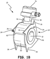
- FIG. 1A is an exploded view of wafer-style process instrument (flow meter) 10, and FIG. 1B is a perspective view of wafer-style flow meter 10.
- Flow meter 10 includes meter flow passage 12, flow meter body (or flow tube) 14, transmitter (or remote junction box) 16, neck 18, wrappers 20, electrical components 22, end plates 24, and cams 26.
- flow meter 10 is a magnetic flow meter.
- flow meter 10 can be any type of flow meter, including but not limited to other velocity flow meters, positive displacement flow meters, and mass flow meters.
- flow meter 10 can be any type of process instrument that uses a wafer-style mounted in a pipe line.
- Meter flow passage 12 forms a tube for directing flow through flow meter body 14.
- Transmitter 16 is connected to flow meter body 14 by neck 18.
- Wrappers 20 are two arcuate halves joined together to form the outer cylinder or housing of flow meter body 14.
- Electrical components 22 (such as field coils and electrodes) can be connected as appropriate to meter flow passage 12, and can be housed within the cylinder formed by wrappers 20.
- End plates 24 are joined to each end of the cylinder formed by wrappers 20. End plates 24 have a series of evenly-spaced cams 26 extending radially outward from flow meter body 14. Cams 26 can be arcuate and gradually increase in size as they extend outward from flow meter body 14 to produce a desired angle (discussed further in FIGS. 3-4 ).
- Flow meter 10 can be assembled by welding wrappers 20 together around meter flow passage 12 to form flow meter body 14.
- Transmitter 16 is connected to flow meter body 14 by neck 18, which is flexible to allow for repositioning of transmitter 16 (discussed further in FIG. 5 ).
- End plates 24 can then be welded to either side of the cylinder of flow meter body 14. In this manner, the components of flow meter 10 can be cut from the same material and welded into a single, leak-proof housing for electrical components 22 of flow meter 10. Further, flow meter body 14 and end plates 24 can be cut to various sizes and shapes to accommodate pipe lines having different sizes and bolt hole patterns.
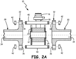
- FIG. 2A is a plan view of wafer-style flow meter 10 positioned between upstream flanged pipe 28 and downstream flanged pipe 30.
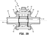
- FIG. 2B is a plan view of wafer-style flow meter 10 installed between upstream flanged pipe 28 and downstream flanged pipe 30.
- Upstream flanged pipe 28 and downstream flanged pipe 30 include flanges 32 and pipe flow passages 34.
- Flanges 32 include lower holes 36 and upper holes 38 for receiving threaded fasteners 40, which are threaded to receive nuts 42. For simplicity, only one upper hole 36 and one lower hole 38 are shown on each flange 32 in FIGS. 2A-2B .
- Flanges 32 can have any number of lower holes 36 and upper holes 38. Threaded fasteners 38 span the distance between upstream flanged pipe 28 and downstream flanged pipe 30 and, together with nuts 42, hold flow meter 10 securely in place.
- Threaded fasteners 40 can be placed in lower holes 36 and fastened by nuts 42 to form a preliminary connection between upstream flanged pipe 28 and downstream flanged pipe 30. Flow meter 10 can then be installed between upstream flanged pipe 28 and downstream flanged pipe 30 such that end plates 24 are flush with flanges 32. Threaded fasteners 40 can then be placed in upper holes 38 and fastened by nuts 42. Nuts 42 can be tightened such that flow meter 10 is suspended between upstream flanged pipe 28 and downstream flanged pipe 30 while still allowing flow meter 10 to be rotated to a desired position to align meter flow passage 12 with pipe flow passages 34 (described further in FIGS. 3-4 ).
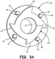
- FIGS. 3-4 illustrate the compatibility of the present invention with a variety of flange bolt hole patterns.
- a single end plate 24 of flow meter 10 is shown with flange 32.
- FIG. 3A is a perspective view of an end plate of a wafer-style flow meter aligned with a pipe flange having four holes and a plurality of threaded fasteners in loose positions.
- FIG. 3B is a perspective view of the end plate aligned with a pipe flange of FIG. 3A with the threaded fasteners in outer limit positions.
- FIG. 4A is a perspective view of an end plate of a wafer-style flow meter aligned with a pipe flange having eight holes and a plurality of threaded fasteners in loose positions.
- FIG. 4B is a perspective view of the end plate aligned with a pipe flange of FIG. 4A with the threaded fasteners in outer limit positions.
- Flange 32 has lower holes 36 and upper holes 38. In the embodiment shown in FIG. 3 , flange 32 has two lower holes 36 and two upper holes 38. In the embodiment shown in FIG. 4 , flange 32 has four lower holes 36 and four upper holes 38. In other embodiments, flange 32 may have any number of lower holes 36 and upper holes 38. End plate 24 has equally spaced cams 26 extending radially outward.
- threaded fasteners 40 are loosely held in lower holes 36 and upper holes 38 of flange 32.
- Lower holes 36 and upper holes 38 are sized such that threaded fasteners 40 are given limited play when initially installed to facilitate connection of pipe flanges 32 on either side of flow meter 10.
- threaded fasteners 40 are pushed to the outer limit of lower holes 36 and upper holes 38 of flange 32.
- cams 26 of end plate 24 engage threaded fasteners 40.
- the arcuate surface of cams 26 push against threaded fasteners 40 such that flow meter 10 can rotate until threaded fasteners 40 reach the outer limit of lower holes 36 and upper holes 38 of flange 32.
- the arcuate surface of cams 26 can extend radially outward from end plate 24 in a variety of angles. The angle required can differ based on the number of lower holes 36 and upper holes 38 of flange 32. In this manner, a variety of end plates 24 having cams 26 extending radially outward at different angles can be joined to flow meter 10 depending on the bolt hole pattern of flanges 32. Cams 26 can thus enable rotation of flow meter 10 until threaded fasteners 40 are pushed to the outer limit position and meter flow passage 12 is aligned with pipe flow passage 34.
- FIG. 5A is an exploded view of flexible neck 44 attached to wafer-style flow meter 10
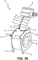
- FIG. 5B is a perspective view of flexible neck 44.
- Flexible neck 44 includes rotatable segments 46.
- Rotatable segments 46 include ridges 48 for sealable engagement with other rotatable segments 46 or transmitter 16.
- Flexible neck 44 extends from flow meter body 14 of flow meter 10, connecting the housing of transmitter 16 to flow meter body 14. Electrical connections between flow meter body 14 and transmitter 16 are made by wires (not shown) that extend through flexible neck 44.
- Flexible neck 44 can have any number of rotatable segments 46 to achieve the desired length and flexibility. Each rotatable segment 46 has a ridge 48 at one end that connects it to other rotatable segments 46. Rotatable segments 46 can be generally cylindrical with one side being shorter than the other. Thus, when rotatable segments 46 are twisted, flexible neck 44 can be twisted into any number of positions. In this manner, transmitter 16 can be repositioned to an optimal orientation after meter flow passage 12 has been aligned with pipe flow passages 34 via the rotation of flow meter body 14 end plates 24 having cams 26.
- the rotatable segments 46 comprise male and female ends to facilitate leak-proof rotation.
Landscapes
- Physics & Mathematics (AREA)
- Fluid Mechanics (AREA)
- General Physics & Mathematics (AREA)
- Measuring Volume Flow (AREA)
- Electromagnetism (AREA)
Claims (12)
- Prozessinstrument (10), umfassend:einen Körper vom Wafer-Typ zur Montage zwischen einem vorgeordneten, mit Flansch versehenen Rohr (28) und einem nachgeordneten, mit Flansch versehenen Rohr (30), wobei der Körper einen Strömungsdurchgang (12) hat;einen Transmitter (16), der an den Prozessinstrumentenkörper (14) angeschlossen ist, um einen Parameter eines durch den Strömungsdurchgang (12) strömenden Prozessfluids zu messen;gekennzeichnet durcheine erste Endplatte (24), die am Körper fixiert ist, wobei die erste Endplatte eine erste Gruppe von Zackengebilden (26) hat, um mehrere mit Gewinde versehene Befestigungselemente (40) in Eingriff zu nehmen, die sich zwischen dem vorgeordneten, mit Flansch versehenen Rohr (28) und dem nachgeordneten, mit Flansch versehenen Rohr (30) erstrecken; undeine zweite Endplatte (24), die am Körper fixiert ist, wobei die zweite Endplatte eine zweite Gruppe von Zackengebilden (26) hat, um die mehreren mit Gewinde versehenen Befestigungselemente (40) in Eingriff zu nehmen, wobei ein Eingriff der ersten Gruppe von Zackengebilden und der zweiten Gruppe von Zackengebilden mit den mehreren Befestigungselementen den Strömungsdurchgang (12) in Bezug auf das vorgeordnete, mit Flansch versehene Rohr (28) und das nachgeordnete, mit Flansch versehene Rohr (30) zentriert, wobei der Transmitter (16) mittels eines umpositionierbaren Halses mit dem Körper verbunden ist, wobei der umpositionierbare Hals eine Reihe von drehbeweglichen Segmenten (46) umfasst, wobei die drehbeweglichen Segmente Einsteck- und Aufnahmeenden umfassen, um eine leckdichte Drehung zu unterstützen.
- Prozessinstrument nach Anspruch 1, wobei die erste Gruppe von Zackengebilden und die zweite Gruppe von Zackengebilden jeweils eine Anzahl von Zackengebildeflächen hat, wobei die Anzahl der Zackengebildeflächen der ersten Gruppe von Zackengebilden gleich der Anzahl von Zackengebildeflächen der zweiten Gruppe von Zackengebilden ist.
- Prozessinstrument nach Anspruch 2, wobei die erste Gruppe von Zackengebilden und die zweite Gruppe von Zackengebilden ausgerichtet sind.
- Prozessinstrument nach Anspruch 3, wobei die Anzahl der Zackengebildeflächen mindestens vier Zackengebildeflächen umfasst.
- Prozessinstrument nach Anspruch 4, wobei sich die mindestens vier Zackengebildeflächen jeweils vom Durchflussmesserkörper in einem bogenförmigen Winkel erstrecken.
- Prozessinstrument nach Anspruch 5, wobei die mindestens vier Zackengebildeflächen tangential eine gleiche Anzahl der mehreren mit Gewinde versehenen Befestigungselemente in Eingriff nehmen, um die gleiche Anzahl der mit Gewinde versehenen Befestigungselemente zwangsläufig zu einer Außenbegrenzung in mehreren entsprechenden Öffnungen (36, 38) zu führen, wobei sich die mehreren entsprechenden Öffnungen an einem vorgeordneten Rohrflansch und einem nachgeordneten Rohrflansch befinden.
- Prozessinstrument nach Anspruch 1, wobei es sich bei dem Prozessinstrument um einen Durchflussmesser handelt.
- Prozessinstrument nach Anspruch 7, wobei der Körper ein Durchflussrohr eines magnetischen Durchflussmessers umfasst.
- Verfahren zum Zentrieren eines Körpers vom Wafer-Typ eines Prozessinstruments (10) zwischen einem vorgeordneten, mit Flansch versehenen Rohr (28) und einem nachgeordneten, mit Flansch versehenen Rohr (30), wobei das Verfahren umfasst:Einsetzen von mehreren mit Gewinde versehenen Befestigungselementen (40) in mehrere entsprechende Öffnungen (36, 38) im vorgeordneten, mit Flansch versehenen Rohr (28) und nachgeordneten, mit Flansch versehenen Rohr (30); undgekennzeichnet durchein Anordnen des Körpers vom Wafer-Typ des Prozessinstruments zwischen dem vorgeordneten, mit Flansch versehenen Rohr (28) und dem nachgeordneten, mit Flansch versehenen Rohr (30) derart, dass eine erste Gruppe von Zackengebilden (26) an einer ersten Endplatte (24), die an einem vorgeordneten Ende des Körpers vom Wafer-Typ fixiert ist, und eine zweite Gruppe von Zackengebilden (26) an einer zweiten Endplatte (24), die an einem nachgeordneten Ende des Körpers vom Wafer-Typ fixiert ist, die mehreren mit Gewinde versehenen Befestigungselemente (40) in Eingriff nehmen, und darüber hinaus ein Anpassen eines umpositionierbaren Halses umfassend, der einen Transmitter mit dem Körper vom Wafer-Typ verbindet, um dadurch eine Ausrichtung des Transmitters (16) anzupassen, wobei der umpositionierbare Hals eine Reihe von drehbeweglichen Segmenten (46) umfasst, wobei die drehbeweglichen Segmente Einsteck- und Aufnahmeenden umfassen, um eine leckdichte Drehung zu unterstützen.
- Verfahren zum Zentrieren eines Körpers vom Wafer-Typ eines Prozessinstruments nach Anspruch 9, wobei das Einsetzen der mehreren mit Gewinde versehenen Befestigungselemente (40) in die mehreren entsprechenden Öffnungen (36, 38) eine erste Stufe und eine zweite Stufe umfasst, wobei die erste Stufe abgeschlossen ist, bevor der Körper vom Wafer-Typ des Prozessinstruments zwischen dem vorgeordneten, mit Flansch versehenen Rohr (28) und dem nachgeordneten, mit Flansch versehenen Rohr (30) installiert wird, und die zweite Stufe abgeschlossen ist, nachdem der Körper vom Wafer-Typ zwischen dem vorgeordneten, mit Flansch versehenen Rohr (28) und dem nachgeordneten, mit Flansch versehenen Rohr (30) installiert wurde.
- Verfahren zum Zentrieren eines Körpers vom Wafer-Typ eines Prozessinstruments nach Anspruch 10, wobei die erste Stufe ein Einsetzen von mindestens zweien der mehreren mit Gewinde versehenen Befestigungselemente (40) in mehrere untere Öffnungspositionen (36) umfasst, und die zweite Stufe ein Einsetzen von mindestens zweien der mehreren mit Gewinde versehenen Befestigungselemente in mehrere obere Öffnungspositionen (38) umfasst.
- Verfahren zum Zentrieren eines Körpers vom Wafer-Typ eines Prozessinstruments nach Anspruch 9, wobei das Positionieren des Körpers vom Wafer-Typ umfasst, den Körper vom Wafer-Typ derart zu drehen, dass die erste Gruppe von Zackengebilden und die zweite Gruppe von Zackengebilden die mehreren mit Gewinde versehenen Befestigungselemente (40) zwangsläufig zu einer Außenbegrenzung in den mehreren entsprechenden Öffnungen (36, 38) führen.
Applications Claiming Priority (2)
| Application Number | Priority Date | Filing Date | Title |
|---|---|---|---|
| US14/502,778 US9255825B1 (en) | 2014-09-30 | 2014-09-30 | Self-aligning wafer-style process instrument |
| PCT/US2015/047510 WO2016053529A1 (en) | 2014-09-30 | 2015-08-28 | Self-aligning wafer-style process instrument |
Publications (3)
| Publication Number | Publication Date |
|---|---|
| EP3201577A1 EP3201577A1 (de) | 2017-08-09 |
| EP3201577A4 EP3201577A4 (de) | 2018-07-04 |
| EP3201577B1 true EP3201577B1 (de) | 2019-11-27 |
Family
ID=54421779
Family Applications (1)
| Application Number | Title | Priority Date | Filing Date |
|---|---|---|---|
| EP15847314.0A Active EP3201577B1 (de) | 2014-09-30 | 2015-08-28 | Selbstausrichtendes prozessinstrument vom wafer-typ |
Country Status (5)
| Country | Link |
|---|---|
| US (1) | US9255825B1 (de) |
| EP (1) | EP3201577B1 (de) |
| JP (1) | JP2017530360A (de) |
| CN (2) | CN105716677B (de) |
| WO (1) | WO2016053529A1 (de) |
Families Citing this family (6)
| Publication number | Priority date | Publication date | Assignee | Title |
|---|---|---|---|---|
| US9255825B1 (en) * | 2014-09-30 | 2016-02-09 | Rosemount Inc. | Self-aligning wafer-style process instrument |
| US9846022B2 (en) * | 2015-09-25 | 2017-12-19 | Dieterich Standard, Inc. | Wafer alignment device |
| DE102016124975A1 (de) * | 2016-12-20 | 2018-06-21 | Endress+Hauser Flowtec Ag | Gehäuse für ein Durchflussmessgerät, und ein Durchflussmessgerät mit einem solchen Gehäuse |
| CN113669527B (zh) * | 2021-08-20 | 2023-06-09 | 中国海洋石油集团有限公司 | 一种管道错位连接装置及方法 |
| CN113758537A (zh) * | 2021-10-08 | 2021-12-07 | 合肥科迈捷智能传感技术有限公司 | 一种用于夹持型流量计安装的定位环 |
| CN114235078B (zh) * | 2021-12-15 | 2023-10-31 | 无锡欧百仪表科技有限公司 | 一种高效低功耗涡轮流量计 |
Family Cites Families (38)
| Publication number | Priority date | Publication date | Assignee | Title |
|---|---|---|---|---|
| US3643983A (en) * | 1969-11-21 | 1972-02-22 | Andrews Ind | Devices for axial alignment of pipe or other flanges |
| JPS526492B2 (de) * | 1971-12-28 | 1977-02-22 | ||
| US4181018A (en) | 1977-02-23 | 1980-01-01 | Fischer & Porter Co. | Unitary electromagnetic flowmeter |
| USRE31444E (en) | 1980-10-31 | 1983-11-15 | Two-phase transformer and welding circuit therefor | |
| JPS61233282A (ja) * | 1985-04-09 | 1986-10-17 | 株式会社椿本チエイン | ケ−ブル等の可撓支持体 |
| JPS6262085U (de) * | 1985-10-08 | 1987-04-17 | ||
| US4986574A (en) | 1990-01-11 | 1991-01-22 | Fisher Controls International, Inc. | Raised face flange alignment tool |
| US5361797A (en) | 1993-06-01 | 1994-11-08 | Schwing America, Inc. | Sludge pipeline lubrication system |
| US5632632A (en) | 1994-09-29 | 1997-05-27 | Rosemount Inc. | Flowmeter alignment device |
| JPH08166267A (ja) * | 1994-12-16 | 1996-06-25 | Toshiba Corp | 電磁流量計装置 |
| JPH1048015A (ja) * | 1996-08-05 | 1998-02-20 | Yokogawa Electric Corp | 電磁流量計 |
| US5814738A (en) | 1997-05-01 | 1998-09-29 | Mccrometer, Inc. | Fluid flow meter and mixer having removable and replaceable displacement member |
| DE19832926A1 (de) * | 1998-07-22 | 2000-01-27 | Gestra Gmbh | Flanschloses Ventilgehäuse für den Einbau zwischen Flansche |
| US7134354B2 (en) * | 1999-09-28 | 2006-11-14 | Rosemount Inc. | Display for process transmitter |
| DE50013695D1 (de) * | 2000-09-07 | 2006-12-14 | Flowtec Ag | Erdungsscheibe |
| JP2002257277A (ja) * | 2001-03-02 | 2002-09-11 | Kubota Corp | 自在曲管 |
| JP2003185482A (ja) | 2001-12-17 | 2003-07-03 | Yokogawa Electric Corp | コリオリ質量流量計 |
| US7284450B2 (en) | 2002-04-09 | 2007-10-23 | Dieterich Standard, Inc. | Averaging orifice primary flow element |
| GB2391278A (en) * | 2002-07-30 | 2004-02-04 | David Williams | Pipe Coupling |
| DE102005002905A1 (de) * | 2005-01-21 | 2006-07-27 | Abb Patent Gmbh | Durchflussmesseinrichtung |
| GB0512619D0 (en) * | 2005-06-21 | 2005-07-27 | Scott Kenneth L | Improvements in or relating to pipelines and method of installation thereof |
| JP4892232B2 (ja) * | 2005-12-16 | 2012-03-07 | 吉佳株式会社 | 組み管ピース、該組み管ピースを用いたライニング用組み管 |
| US7703745B2 (en) * | 2006-04-25 | 2010-04-27 | Fisher Controls International Llc | Seal retainer/longitudinal centering clips with multiple flange capability |
| US7845688B2 (en) * | 2007-04-04 | 2010-12-07 | Savant Measurement Corporation | Multiple material piping component |
| US7472608B2 (en) | 2007-04-04 | 2009-01-06 | Rosemount Inc. | Flangeless differential pressure transmitter for industrial process control systems |
| US9254499B2 (en) * | 2007-10-24 | 2016-02-09 | Michael Klicpera | Apparatus for displaying shower or bath water parameters |
| US7637169B2 (en) | 2008-01-25 | 2009-12-29 | Rosemount, Inc. | Flangeless magnetic flowmeter with integrated retention collar, valve seat and liner protector |
| JP5462496B2 (ja) * | 2009-02-09 | 2014-04-02 | 富士工業株式会社 | 筒状型自在継手 |
| DE102009002053A1 (de) * | 2009-03-31 | 2010-10-07 | Endress + Hauser Flowtec Ag | Magnetisch-induktive Durchflussmesseinrichtung |
| EP2375225A1 (de) * | 2010-04-12 | 2011-10-12 | Itron France | Verbindungsvorrichtung zwischen einer hydraulischen und einer elektronischen Vorrichtung |
| US9182258B2 (en) | 2011-06-28 | 2015-11-10 | Rosemount Inc. | Variable frequency magnetic flowmeter |
| EP2753854B1 (de) * | 2011-09-08 | 2019-11-20 | BS & B Safety Systems Limited | Sicherheitskopf |
| US9032815B2 (en) * | 2011-10-05 | 2015-05-19 | Saudi Arabian Oil Company | Pulsating flow meter having a bluff body and an orifice plate to produce a pulsating flow |
| US8739638B1 (en) * | 2011-11-22 | 2014-06-03 | The United States Of America As Represented By The Administrator Of The National Aeronautics And Space Administration | Star-shaped fluid flow tool for use in making differential measurements |
| US8991264B2 (en) * | 2012-09-26 | 2015-03-31 | Rosemount Inc. | Integrally molded magnetic flowmeter |
| US9021890B2 (en) * | 2012-09-26 | 2015-05-05 | Rosemount Inc. | Magnetic flowmeter with multiple coils |
| US9027418B2 (en) * | 2012-09-28 | 2015-05-12 | Rosemount Inc. | Magnetic flowmeter |
| US9255825B1 (en) * | 2014-09-30 | 2016-02-09 | Rosemount Inc. | Self-aligning wafer-style process instrument |
-
2014
- 2014-09-30 US US14/502,778 patent/US9255825B1/en active Active
- 2014-12-05 CN CN201410737317.3A patent/CN105716677B/zh active Active
- 2014-12-05 CN CN201420761127.0U patent/CN204740048U/zh not_active Withdrawn - After Issue
-
2015
- 2015-08-28 EP EP15847314.0A patent/EP3201577B1/de active Active
- 2015-08-28 JP JP2017516500A patent/JP2017530360A/ja active Pending
- 2015-08-28 WO PCT/US2015/047510 patent/WO2016053529A1/en not_active Ceased
Non-Patent Citations (1)
| Title |
|---|
| None * |
Also Published As
| Publication number | Publication date |
|---|---|
| CN105716677A (zh) | 2016-06-29 |
| CN204740048U (zh) | 2015-11-04 |
| EP3201577A4 (de) | 2018-07-04 |
| US9255825B1 (en) | 2016-02-09 |
| CN105716677B (zh) | 2020-04-14 |
| JP2017530360A (ja) | 2017-10-12 |
| EP3201577A1 (de) | 2017-08-09 |
| WO2016053529A1 (en) | 2016-04-07 |
Similar Documents
| Publication | Publication Date | Title |
|---|---|---|
| EP3201577B1 (de) | Selbstausrichtendes prozessinstrument vom wafer-typ | |
| CN110332963B (zh) | 一体式孔板组件 | |
| EP2521897B1 (de) | Ultraschallflussmesser- und energieumwandleranordnung mit isolierter transformatorkapsel | |
| US9334886B2 (en) | Flow conditioner with integral vanes | |
| US8132469B2 (en) | Ultrasonic flow meter with transducer assembly having a rotatable receptacle and elbow connector | |
| US9541107B2 (en) | Flow conditioner with integral vanes | |
| US20170009788A1 (en) | Pipe Assembly With Stepped Flow Conditioners | |
| JP6491327B2 (ja) | ラグ形化工されたウェハ位置調整リング | |
| US9625293B2 (en) | Flow conditioner having integral pressure tap | |
| CN204269166U (zh) | 晶片型电磁流量传感器 | |
| CN103649690B (zh) | 电磁流量计以及其接地方法 | |
| HK1175838B (en) | Ultrasonic flow meter and transducer assembly with isolated transformer capsule |
Legal Events
| Date | Code | Title | Description |
|---|---|---|---|
| STAA | Information on the status of an ep patent application or granted ep patent |
Free format text: STATUS: THE INTERNATIONAL PUBLICATION HAS BEEN MADE |
|
| PUAI | Public reference made under article 153(3) epc to a published international application that has entered the european phase |
Free format text: ORIGINAL CODE: 0009012 |
|
| STAA | Information on the status of an ep patent application or granted ep patent |
Free format text: STATUS: REQUEST FOR EXAMINATION WAS MADE |
|
| 17P | Request for examination filed |
Effective date: 20170223 |
|
| AK | Designated contracting states |
Kind code of ref document: A1 Designated state(s): AL AT BE BG CH CY CZ DE DK EE ES FI FR GB GR HR HU IE IS IT LI LT LU LV MC MK MT NL NO PL PT RO RS SE SI SK SM TR |
|
| AX | Request for extension of the european patent |
Extension state: BA ME |
|
| DAV | Request for validation of the european patent (deleted) | ||
| DAX | Request for extension of the european patent (deleted) | ||
| A4 | Supplementary search report drawn up and despatched |
Effective date: 20180601 |
|
| RIC1 | Information provided on ipc code assigned before grant |
Ipc: G01F 1/58 20060101ALN20180525BHEP Ipc: G01F 15/14 20060101AFI20180525BHEP Ipc: F16L 23/06 20060101ALI20180525BHEP Ipc: G01F 15/18 20060101ALI20180525BHEP Ipc: F16L 23/04 20060101ALI20180525BHEP Ipc: F16L 23/02 20060101ALI20180525BHEP Ipc: G01F 15/00 20060101ALI20180525BHEP Ipc: G01F 1/00 20060101ALI20180525BHEP |
|
| REG | Reference to a national code |
Ref country code: DE Ref legal event code: R079 Ref document number: 602015042684 Country of ref document: DE Free format text: PREVIOUS MAIN CLASS: G01F0015000000 Ipc: G01F0015140000 |
|
| RIC1 | Information provided on ipc code assigned before grant |
Ipc: G01F 1/00 20060101ALI20190508BHEP Ipc: G01F 15/14 20060101AFI20190508BHEP Ipc: G01F 15/00 20060101ALI20190508BHEP Ipc: F16L 23/04 20060101ALI20190508BHEP Ipc: G01F 1/58 20060101ALN20190508BHEP Ipc: G01F 15/18 20060101ALI20190508BHEP Ipc: F16L 23/06 20060101ALI20190508BHEP Ipc: F16L 23/02 20060101ALI20190508BHEP |
|
| GRAP | Despatch of communication of intention to grant a patent |
Free format text: ORIGINAL CODE: EPIDOSNIGR1 |
|
| STAA | Information on the status of an ep patent application or granted ep patent |
Free format text: STATUS: GRANT OF PATENT IS INTENDED |
|
| RIC1 | Information provided on ipc code assigned before grant |
Ipc: G01F 1/58 20060101ALN20190516BHEP Ipc: G01F 15/14 20060101AFI20190516BHEP Ipc: F16L 23/04 20060101ALI20190516BHEP Ipc: G01F 15/00 20060101ALI20190516BHEP Ipc: F16L 23/02 20060101ALI20190516BHEP Ipc: F16L 23/06 20060101ALI20190516BHEP Ipc: G01F 1/00 20060101ALI20190516BHEP Ipc: G01F 15/18 20060101ALI20190516BHEP |
|
| RIC1 | Information provided on ipc code assigned before grant |
Ipc: G01F 1/00 20060101ALI20190520BHEP Ipc: F16L 23/02 20060101ALI20190520BHEP Ipc: F16L 23/04 20060101ALI20190520BHEP Ipc: G01F 1/58 20060101ALN20190520BHEP Ipc: G01F 15/14 20060101AFI20190520BHEP Ipc: G01F 15/18 20060101ALI20190520BHEP Ipc: F16L 23/06 20060101ALI20190520BHEP Ipc: G01F 15/00 20060101ALI20190520BHEP |
|
| INTG | Intention to grant announced |
Effective date: 20190614 |
|
| GRAS | Grant fee paid |
Free format text: ORIGINAL CODE: EPIDOSNIGR3 |
|
| GRAA | (expected) grant |
Free format text: ORIGINAL CODE: 0009210 |
|
| STAA | Information on the status of an ep patent application or granted ep patent |
Free format text: STATUS: THE PATENT HAS BEEN GRANTED |
|
| AK | Designated contracting states |
Kind code of ref document: B1 Designated state(s): AL AT BE BG CH CY CZ DE DK EE ES FI FR GB GR HR HU IE IS IT LI LT LU LV MC MK MT NL NO PL PT RO RS SE SI SK SM TR |
|
| REG | Reference to a national code |
Ref country code: GB Ref legal event code: FG4D |
|
| REG | Reference to a national code |
Ref country code: CH Ref legal event code: EP Ref country code: CH Ref legal event code: NV Representative=s name: FELBER UND PARTNER AG, CH |
|
| REG | Reference to a national code |
Ref country code: AT Ref legal event code: REF Ref document number: 1207208 Country of ref document: AT Kind code of ref document: T Effective date: 20191215 |
|
| REG | Reference to a national code |
Ref country code: DE Ref legal event code: R096 Ref document number: 602015042684 Country of ref document: DE |
|
| REG | Reference to a national code |
Ref country code: IE Ref legal event code: FG4D |
|
| REG | Reference to a national code |
Ref country code: NL Ref legal event code: MP Effective date: 20191127 |
|
| REG | Reference to a national code |
Ref country code: LT Ref legal event code: MG4D |
|
| PG25 | Lapsed in a contracting state [announced via postgrant information from national office to epo] |
Ref country code: NL Free format text: LAPSE BECAUSE OF FAILURE TO SUBMIT A TRANSLATION OF THE DESCRIPTION OR TO PAY THE FEE WITHIN THE PRESCRIBED TIME-LIMIT Effective date: 20191127 Ref country code: LT Free format text: LAPSE BECAUSE OF FAILURE TO SUBMIT A TRANSLATION OF THE DESCRIPTION OR TO PAY THE FEE WITHIN THE PRESCRIBED TIME-LIMIT Effective date: 20191127 Ref country code: GR Free format text: LAPSE BECAUSE OF FAILURE TO SUBMIT A TRANSLATION OF THE DESCRIPTION OR TO PAY THE FEE WITHIN THE PRESCRIBED TIME-LIMIT Effective date: 20200228 Ref country code: NO Free format text: LAPSE BECAUSE OF FAILURE TO SUBMIT A TRANSLATION OF THE DESCRIPTION OR TO PAY THE FEE WITHIN THE PRESCRIBED TIME-LIMIT Effective date: 20200227 Ref country code: SE Free format text: LAPSE BECAUSE OF FAILURE TO SUBMIT A TRANSLATION OF THE DESCRIPTION OR TO PAY THE FEE WITHIN THE PRESCRIBED TIME-LIMIT Effective date: 20191127 Ref country code: LV Free format text: LAPSE BECAUSE OF FAILURE TO SUBMIT A TRANSLATION OF THE DESCRIPTION OR TO PAY THE FEE WITHIN THE PRESCRIBED TIME-LIMIT Effective date: 20191127 Ref country code: BG Free format text: LAPSE BECAUSE OF FAILURE TO SUBMIT A TRANSLATION OF THE DESCRIPTION OR TO PAY THE FEE WITHIN THE PRESCRIBED TIME-LIMIT Effective date: 20200227 Ref country code: FI Free format text: LAPSE BECAUSE OF FAILURE TO SUBMIT A TRANSLATION OF THE DESCRIPTION OR TO PAY THE FEE WITHIN THE PRESCRIBED TIME-LIMIT Effective date: 20191127 |
|
| PG25 | Lapsed in a contracting state [announced via postgrant information from national office to epo] |
Ref country code: RS Free format text: LAPSE BECAUSE OF FAILURE TO SUBMIT A TRANSLATION OF THE DESCRIPTION OR TO PAY THE FEE WITHIN THE PRESCRIBED TIME-LIMIT Effective date: 20191127 Ref country code: IS Free format text: LAPSE BECAUSE OF FAILURE TO SUBMIT A TRANSLATION OF THE DESCRIPTION OR TO PAY THE FEE WITHIN THE PRESCRIBED TIME-LIMIT Effective date: 20200327 Ref country code: HR Free format text: LAPSE BECAUSE OF FAILURE TO SUBMIT A TRANSLATION OF THE DESCRIPTION OR TO PAY THE FEE WITHIN THE PRESCRIBED TIME-LIMIT Effective date: 20191127 |
|
| PG25 | Lapsed in a contracting state [announced via postgrant information from national office to epo] |
Ref country code: AL Free format text: LAPSE BECAUSE OF FAILURE TO SUBMIT A TRANSLATION OF THE DESCRIPTION OR TO PAY THE FEE WITHIN THE PRESCRIBED TIME-LIMIT Effective date: 20191127 |
|
| PG25 | Lapsed in a contracting state [announced via postgrant information from national office to epo] |
Ref country code: PT Free format text: LAPSE BECAUSE OF FAILURE TO SUBMIT A TRANSLATION OF THE DESCRIPTION OR TO PAY THE FEE WITHIN THE PRESCRIBED TIME-LIMIT Effective date: 20200419 Ref country code: EE Free format text: LAPSE BECAUSE OF FAILURE TO SUBMIT A TRANSLATION OF THE DESCRIPTION OR TO PAY THE FEE WITHIN THE PRESCRIBED TIME-LIMIT Effective date: 20191127 Ref country code: DK Free format text: LAPSE BECAUSE OF FAILURE TO SUBMIT A TRANSLATION OF THE DESCRIPTION OR TO PAY THE FEE WITHIN THE PRESCRIBED TIME-LIMIT Effective date: 20191127 Ref country code: RO Free format text: LAPSE BECAUSE OF FAILURE TO SUBMIT A TRANSLATION OF THE DESCRIPTION OR TO PAY THE FEE WITHIN THE PRESCRIBED TIME-LIMIT Effective date: 20191127 Ref country code: ES Free format text: LAPSE BECAUSE OF FAILURE TO SUBMIT A TRANSLATION OF THE DESCRIPTION OR TO PAY THE FEE WITHIN THE PRESCRIBED TIME-LIMIT Effective date: 20191127 Ref country code: CZ Free format text: LAPSE BECAUSE OF FAILURE TO SUBMIT A TRANSLATION OF THE DESCRIPTION OR TO PAY THE FEE WITHIN THE PRESCRIBED TIME-LIMIT Effective date: 20191127 |
|
| REG | Reference to a national code |
Ref country code: DE Ref legal event code: R097 Ref document number: 602015042684 Country of ref document: DE |
|
| PG25 | Lapsed in a contracting state [announced via postgrant information from national office to epo] |
Ref country code: SM Free format text: LAPSE BECAUSE OF FAILURE TO SUBMIT A TRANSLATION OF THE DESCRIPTION OR TO PAY THE FEE WITHIN THE PRESCRIBED TIME-LIMIT Effective date: 20191127 Ref country code: SK Free format text: LAPSE BECAUSE OF FAILURE TO SUBMIT A TRANSLATION OF THE DESCRIPTION OR TO PAY THE FEE WITHIN THE PRESCRIBED TIME-LIMIT Effective date: 20191127 |
|
| REG | Reference to a national code |
Ref country code: AT Ref legal event code: MK05 Ref document number: 1207208 Country of ref document: AT Kind code of ref document: T Effective date: 20191127 |
|
| PLBE | No opposition filed within time limit |
Free format text: ORIGINAL CODE: 0009261 |
|
| STAA | Information on the status of an ep patent application or granted ep patent |
Free format text: STATUS: NO OPPOSITION FILED WITHIN TIME LIMIT |
|
| 26N | No opposition filed |
Effective date: 20200828 |
|
| PG25 | Lapsed in a contracting state [announced via postgrant information from national office to epo] |
Ref country code: SI Free format text: LAPSE BECAUSE OF FAILURE TO SUBMIT A TRANSLATION OF THE DESCRIPTION OR TO PAY THE FEE WITHIN THE PRESCRIBED TIME-LIMIT Effective date: 20191127 Ref country code: PL Free format text: LAPSE BECAUSE OF FAILURE TO SUBMIT A TRANSLATION OF THE DESCRIPTION OR TO PAY THE FEE WITHIN THE PRESCRIBED TIME-LIMIT Effective date: 20191127 Ref country code: AT Free format text: LAPSE BECAUSE OF FAILURE TO SUBMIT A TRANSLATION OF THE DESCRIPTION OR TO PAY THE FEE WITHIN THE PRESCRIBED TIME-LIMIT Effective date: 20191127 |
|
| PG25 | Lapsed in a contracting state [announced via postgrant information from national office to epo] |
Ref country code: IT Free format text: LAPSE BECAUSE OF FAILURE TO SUBMIT A TRANSLATION OF THE DESCRIPTION OR TO PAY THE FEE WITHIN THE PRESCRIBED TIME-LIMIT Effective date: 20191127 |
|
| PG25 | Lapsed in a contracting state [announced via postgrant information from national office to epo] |
Ref country code: MC Free format text: LAPSE BECAUSE OF FAILURE TO SUBMIT A TRANSLATION OF THE DESCRIPTION OR TO PAY THE FEE WITHIN THE PRESCRIBED TIME-LIMIT Effective date: 20191127 |
|
| GBPC | Gb: european patent ceased through non-payment of renewal fee |
Effective date: 20200828 |
|
| PG25 | Lapsed in a contracting state [announced via postgrant information from national office to epo] |
Ref country code: LU Free format text: LAPSE BECAUSE OF NON-PAYMENT OF DUE FEES Effective date: 20200828 |
|
| REG | Reference to a national code |
Ref country code: BE Ref legal event code: MM Effective date: 20200831 |
|
| PG25 | Lapsed in a contracting state [announced via postgrant information from national office to epo] |
Ref country code: FR Free format text: LAPSE BECAUSE OF NON-PAYMENT OF DUE FEES Effective date: 20200831 |
|
| PG25 | Lapsed in a contracting state [announced via postgrant information from national office to epo] |
Ref country code: IE Free format text: LAPSE BECAUSE OF NON-PAYMENT OF DUE FEES Effective date: 20200828 Ref country code: GB Free format text: LAPSE BECAUSE OF NON-PAYMENT OF DUE FEES Effective date: 20200828 Ref country code: BE Free format text: LAPSE BECAUSE OF NON-PAYMENT OF DUE FEES Effective date: 20200831 |
|
| PG25 | Lapsed in a contracting state [announced via postgrant information from national office to epo] |
Ref country code: TR Free format text: LAPSE BECAUSE OF FAILURE TO SUBMIT A TRANSLATION OF THE DESCRIPTION OR TO PAY THE FEE WITHIN THE PRESCRIBED TIME-LIMIT Effective date: 20191127 Ref country code: MT Free format text: LAPSE BECAUSE OF FAILURE TO SUBMIT A TRANSLATION OF THE DESCRIPTION OR TO PAY THE FEE WITHIN THE PRESCRIBED TIME-LIMIT Effective date: 20191127 Ref country code: CY Free format text: LAPSE BECAUSE OF FAILURE TO SUBMIT A TRANSLATION OF THE DESCRIPTION OR TO PAY THE FEE WITHIN THE PRESCRIBED TIME-LIMIT Effective date: 20191127 |
|
| PG25 | Lapsed in a contracting state [announced via postgrant information from national office to epo] |
Ref country code: MK Free format text: LAPSE BECAUSE OF FAILURE TO SUBMIT A TRANSLATION OF THE DESCRIPTION OR TO PAY THE FEE WITHIN THE PRESCRIBED TIME-LIMIT Effective date: 20191127 |
|
| P01 | Opt-out of the competence of the unified patent court (upc) registered |
Effective date: 20231208 |
|
| PGFP | Annual fee paid to national office [announced via postgrant information from national office to epo] |
Ref country code: DE Payment date: 20250724 Year of fee payment: 11 |
|
| PGFP | Annual fee paid to national office [announced via postgrant information from national office to epo] |
Ref country code: CH Payment date: 20250901 Year of fee payment: 11 |