EP3201967B1 - Modular approach for advanced battery modules having different electrical characteristics - Google Patents
Modular approach for advanced battery modules having different electrical characteristics Download PDFInfo
- Publication number
- EP3201967B1 EP3201967B1 EP15738164.1A EP15738164A EP3201967B1 EP 3201967 B1 EP3201967 B1 EP 3201967B1 EP 15738164 A EP15738164 A EP 15738164A EP 3201967 B1 EP3201967 B1 EP 3201967B1
- Authority
- EP
- European Patent Office
- Prior art keywords
- lithium ion
- battery module
- ion battery
- housing
- region
- Prior art date
- Legal status (The legal status is an assumption and is not a legal conclusion. Google has not performed a legal analysis and makes no representation as to the accuracy of the status listed.)
- Active
Links
Images




Classifications
-
- H—ELECTRICITY
- H01—ELECTRIC ELEMENTS
- H01M—PROCESSES OR MEANS, e.g. BATTERIES, FOR THE DIRECT CONVERSION OF CHEMICAL ENERGY INTO ELECTRICAL ENERGY
- H01M10/00—Secondary cells; Manufacture thereof
- H01M10/05—Accumulators with non-aqueous electrolyte
- H01M10/052—Li-accumulators
- H01M10/0525—Rocking-chair batteries, i.e. batteries with lithium insertion or intercalation in both electrodes; Lithium-ion batteries
-
- H—ELECTRICITY
- H01—ELECTRIC ELEMENTS
- H01M—PROCESSES OR MEANS, e.g. BATTERIES, FOR THE DIRECT CONVERSION OF CHEMICAL ENERGY INTO ELECTRICAL ENERGY
- H01M50/00—Constructional details or processes of manufacture of the non-active parts of electrochemical cells other than fuel cells, e.g. hybrid cells
- H01M50/20—Mountings; Secondary casings or frames; Racks, modules or packs; Suspension devices; Shock absorbers; Transport or carrying devices; Holders
- H01M50/267—Mountings; Secondary casings or frames; Racks, modules or packs; Suspension devices; Shock absorbers; Transport or carrying devices; Holders having means for adapting to batteries or cells of different types or different sizes
-
- H—ELECTRICITY
- H01—ELECTRIC ELEMENTS
- H01M—PROCESSES OR MEANS, e.g. BATTERIES, FOR THE DIRECT CONVERSION OF CHEMICAL ENERGY INTO ELECTRICAL ENERGY
- H01M10/00—Secondary cells; Manufacture thereof
- H01M10/42—Methods or arrangements for servicing or maintenance of secondary cells or secondary half-cells
- H01M10/425—Structural combination with electronic components, e.g. electronic circuits integrated to the outside of the casing
-
- H—ELECTRICITY
- H01—ELECTRIC ELEMENTS
- H01M—PROCESSES OR MEANS, e.g. BATTERIES, FOR THE DIRECT CONVERSION OF CHEMICAL ENERGY INTO ELECTRICAL ENERGY
- H01M4/00—Electrodes
- H01M4/02—Electrodes composed of, or comprising, active material
- H01M4/36—Selection of substances as active materials, active masses, active liquids
- H01M4/48—Selection of substances as active materials, active masses, active liquids of inorganic oxides or hydroxides
- H01M4/485—Selection of substances as active materials, active masses, active liquids of inorganic oxides or hydroxides of mixed oxides or hydroxides for inserting or intercalating light metals, e.g. LiTi2O4 or LiTi2OxFy
-
- H—ELECTRICITY
- H01—ELECTRIC ELEMENTS
- H01M—PROCESSES OR MEANS, e.g. BATTERIES, FOR THE DIRECT CONVERSION OF CHEMICAL ENERGY INTO ELECTRICAL ENERGY
- H01M4/00—Electrodes
- H01M4/02—Electrodes composed of, or comprising, active material
- H01M4/36—Selection of substances as active materials, active masses, active liquids
- H01M4/48—Selection of substances as active materials, active masses, active liquids of inorganic oxides or hydroxides
- H01M4/50—Selection of substances as active materials, active masses, active liquids of inorganic oxides or hydroxides of manganese
- H01M4/505—Selection of substances as active materials, active masses, active liquids of inorganic oxides or hydroxides of manganese of mixed oxides or hydroxides containing manganese for inserting or intercalating light metals, e.g. LiMn2O4 or LiMn2OxFy
-
- H—ELECTRICITY
- H01—ELECTRIC ELEMENTS
- H01M—PROCESSES OR MEANS, e.g. BATTERIES, FOR THE DIRECT CONVERSION OF CHEMICAL ENERGY INTO ELECTRICAL ENERGY
- H01M4/00—Electrodes
- H01M4/02—Electrodes composed of, or comprising, active material
- H01M4/36—Selection of substances as active materials, active masses, active liquids
- H01M4/48—Selection of substances as active materials, active masses, active liquids of inorganic oxides or hydroxides
- H01M4/52—Selection of substances as active materials, active masses, active liquids of inorganic oxides or hydroxides of nickel, cobalt or iron
- H01M4/525—Selection of substances as active materials, active masses, active liquids of inorganic oxides or hydroxides of nickel, cobalt or iron of mixed oxides or hydroxides containing iron, cobalt or nickel for inserting or intercalating light metals, e.g. LiNiO2, LiCoO2 or LiCoOxFy
-
- H—ELECTRICITY
- H01—ELECTRIC ELEMENTS
- H01M—PROCESSES OR MEANS, e.g. BATTERIES, FOR THE DIRECT CONVERSION OF CHEMICAL ENERGY INTO ELECTRICAL ENERGY
- H01M50/00—Constructional details or processes of manufacture of the non-active parts of electrochemical cells other than fuel cells, e.g. hybrid cells
- H01M50/20—Mountings; Secondary casings or frames; Racks, modules or packs; Suspension devices; Shock absorbers; Transport or carrying devices; Holders
- H01M50/271—Lids or covers for the racks or secondary casings
-
- B—PERFORMING OPERATIONS; TRANSPORTING
- B60—VEHICLES IN GENERAL
- B60L—PROPULSION OF ELECTRICALLY-PROPELLED VEHICLES; SUPPLYING ELECTRIC POWER FOR AUXILIARY EQUIPMENT OF ELECTRICALLY-PROPELLED VEHICLES; ELECTRODYNAMIC BRAKE SYSTEMS FOR VEHICLES IN GENERAL; MAGNETIC SUSPENSION OR LEVITATION FOR VEHICLES; MONITORING OPERATING VARIABLES OF ELECTRICALLY-PROPELLED VEHICLES; ELECTRIC SAFETY DEVICES FOR ELECTRICALLY-PROPELLED VEHICLES
- B60L50/00—Electric propulsion with power supplied within the vehicle
- B60L50/50—Electric propulsion with power supplied within the vehicle using propulsion power supplied by batteries or fuel cells
- B60L50/60—Electric propulsion with power supplied within the vehicle using propulsion power supplied by batteries or fuel cells using power supplied by batteries
- B60L50/64—Constructional details of batteries specially adapted for electric vehicles
-
- H—ELECTRICITY
- H01—ELECTRIC ELEMENTS
- H01M—PROCESSES OR MEANS, e.g. BATTERIES, FOR THE DIRECT CONVERSION OF CHEMICAL ENERGY INTO ELECTRICAL ENERGY
- H01M10/00—Secondary cells; Manufacture thereof
- H01M10/60—Heating or cooling; Temperature control
- H01M10/61—Types of temperature control
- H01M10/613—Cooling or keeping cold
-
- H—ELECTRICITY
- H01—ELECTRIC ELEMENTS
- H01M—PROCESSES OR MEANS, e.g. BATTERIES, FOR THE DIRECT CONVERSION OF CHEMICAL ENERGY INTO ELECTRICAL ENERGY
- H01M10/00—Secondary cells; Manufacture thereof
- H01M10/60—Heating or cooling; Temperature control
- H01M10/62—Heating or cooling; Temperature control specially adapted for specific applications
- H01M10/625—Vehicles
-
- H—ELECTRICITY
- H01—ELECTRIC ELEMENTS
- H01M—PROCESSES OR MEANS, e.g. BATTERIES, FOR THE DIRECT CONVERSION OF CHEMICAL ENERGY INTO ELECTRICAL ENERGY
- H01M10/00—Secondary cells; Manufacture thereof
- H01M10/60—Heating or cooling; Temperature control
- H01M10/65—Means for temperature control structurally associated with the cells
- H01M10/656—Means for temperature control structurally associated with the cells characterised by the type of heat-exchange fluid
- H01M10/6561—Gases
- H01M10/6563—Gases with forced flow, e.g. by blowers
-
- H—ELECTRICITY
- H01—ELECTRIC ELEMENTS
- H01M—PROCESSES OR MEANS, e.g. BATTERIES, FOR THE DIRECT CONVERSION OF CHEMICAL ENERGY INTO ELECTRICAL ENERGY
- H01M2220/00—Batteries for particular applications
- H01M2220/20—Batteries in motive systems, e.g. vehicle, ship, plane
-
- H—ELECTRICITY
- H01—ELECTRIC ELEMENTS
- H01M—PROCESSES OR MEANS, e.g. BATTERIES, FOR THE DIRECT CONVERSION OF CHEMICAL ENERGY INTO ELECTRICAL ENERGY
- H01M50/00—Constructional details or processes of manufacture of the non-active parts of electrochemical cells other than fuel cells, e.g. hybrid cells
- H01M50/20—Mountings; Secondary casings or frames; Racks, modules or packs; Suspension devices; Shock absorbers; Transport or carrying devices; Holders
- H01M50/204—Racks, modules or packs for multiple batteries or multiple cells
- H01M50/207—Racks, modules or packs for multiple batteries or multiple cells characterised by their shape
- H01M50/209—Racks, modules or packs for multiple batteries or multiple cells characterised by their shape adapted for prismatic or rectangular cells
-
- H—ELECTRICITY
- H01—ELECTRIC ELEMENTS
- H01M—PROCESSES OR MEANS, e.g. BATTERIES, FOR THE DIRECT CONVERSION OF CHEMICAL ENERGY INTO ELECTRICAL ENERGY
- H01M50/00—Constructional details or processes of manufacture of the non-active parts of electrochemical cells other than fuel cells, e.g. hybrid cells
- H01M50/20—Mountings; Secondary casings or frames; Racks, modules or packs; Suspension devices; Shock absorbers; Transport or carrying devices; Holders
- H01M50/249—Mountings; Secondary casings or frames; Racks, modules or packs; Suspension devices; Shock absorbers; Transport or carrying devices; Holders specially adapted for aircraft or vehicles, e.g. cars or trains
-
- Y—GENERAL TAGGING OF NEW TECHNOLOGICAL DEVELOPMENTS; GENERAL TAGGING OF CROSS-SECTIONAL TECHNOLOGIES SPANNING OVER SEVERAL SECTIONS OF THE IPC; TECHNICAL SUBJECTS COVERED BY FORMER USPC CROSS-REFERENCE ART COLLECTIONS [XRACs] AND DIGESTS
- Y02—TECHNOLOGIES OR APPLICATIONS FOR MITIGATION OR ADAPTATION AGAINST CLIMATE CHANGE
- Y02E—REDUCTION OF GREENHOUSE GAS [GHG] EMISSIONS, RELATED TO ENERGY GENERATION, TRANSMISSION OR DISTRIBUTION
- Y02E60/00—Enabling technologies; Technologies with a potential or indirect contribution to GHG emissions mitigation
- Y02E60/10—Energy storage using batteries
-
- Y—GENERAL TAGGING OF NEW TECHNOLOGICAL DEVELOPMENTS; GENERAL TAGGING OF CROSS-SECTIONAL TECHNOLOGIES SPANNING OVER SEVERAL SECTIONS OF THE IPC; TECHNICAL SUBJECTS COVERED BY FORMER USPC CROSS-REFERENCE ART COLLECTIONS [XRACs] AND DIGESTS
- Y02—TECHNOLOGIES OR APPLICATIONS FOR MITIGATION OR ADAPTATION AGAINST CLIMATE CHANGE
- Y02P—CLIMATE CHANGE MITIGATION TECHNOLOGIES IN THE PRODUCTION OR PROCESSING OF GOODS
- Y02P70/00—Climate change mitigation technologies in the production process for final industrial or consumer products
- Y02P70/50—Manufacturing or production processes characterised by the final manufactured product
-
- Y—GENERAL TAGGING OF NEW TECHNOLOGICAL DEVELOPMENTS; GENERAL TAGGING OF CROSS-SECTIONAL TECHNOLOGIES SPANNING OVER SEVERAL SECTIONS OF THE IPC; TECHNICAL SUBJECTS COVERED BY FORMER USPC CROSS-REFERENCE ART COLLECTIONS [XRACs] AND DIGESTS
- Y02—TECHNOLOGIES OR APPLICATIONS FOR MITIGATION OR ADAPTATION AGAINST CLIMATE CHANGE
- Y02T—CLIMATE CHANGE MITIGATION TECHNOLOGIES RELATED TO TRANSPORTATION
- Y02T10/00—Road transport of goods or passengers
- Y02T10/60—Other road transportation technologies with climate change mitigation effect
- Y02T10/70—Energy storage systems for electromobility, e.g. batteries
Definitions
- the present disclosure relates generally to the field of batteries and battery modules. More specifically, the present disclosure relates to water management features for Lithium-ion (Li-ion) battery modules.
- xEV A vehicle that uses one or more battery systems for providing all or a portion of the motive power for the vehicle can be referred to as an xEV, where the term "xEV” is defined herein to include all of the following vehicles, or any variations or combinations thereof, that use electric power for all or a portion of their vehicular motive force.
- xEVs include electric vehicles (EVs) that utilize electric power for all motive force.
- EVs electric vehicles
- hybrid electric vehicles (HEVs) also considered xEVs, combine an internal combustion engine propulsion system and a battery-powered electric propulsion system, such as 48 Volt (V) or 130V systems.
- the term HEV may include any variation of a hybrid electric vehicle.
- full hybrid systems may provide motive and other electrical power to the vehicle using one or more electric motors, using only an internal combustion engine, or using both.
- mild hybrid systems MHEVs
- MHEVs disable the internal combustion engine when the vehicle is idling and utilize a battery system to continue powering the air conditioning unit, radio, or other electronics, as well as to restart the engine when propulsion is desired.
- the mild hybrid system may also apply some level of power assist, during acceleration for example, to supplement the internal combustion engine.
- Mild hybrids are typically 96V to 130V and recover braking energy through a belt or crank integrated starter generator.
- a micro-hybrid electric vehicle also uses a "Stop-Start" system similar to the mild hybrids, but the micro-hybrid systems of a mHEV may or may not supply power assist to the internal combustion engine and operates at a voltage below 60V.
- mHEVs typically do not technically use electric power provided directly to the crankshaft or transmission for any portion of the motive force of the vehicle, but an mHEV may still be considered as an xEV since it does use electric power to supplement a vehicle's power needs when the vehicle is idling with internal combustion engine disabled and recovers braking energy through an integrated starter generator.
- a plug-in electric vehicle is any vehicle that can be charged from an external source of electricity, such as wall sockets, and the energy stored in the rechargeable battery packs drives or contributes to drive the wheels.
- PEVs are a subcategory of EVs that include all-electric or battery electric vehicles (BEVs), plug-in hybrid electric vehicles (PHEVs), and electric vehicle conversions of hybrid electric vehicles and conventional internal combustion engine vehicles.
- xEVs as described above may provide a number of advantages as compared to more traditional gas-powered vehicles using only internal combustion engines and traditional electrical systems, which are typically 12V systems powered by a lead acid battery.
- xEVs may produce fewer undesirable emission products and may exhibit greater fuel efficiency as compared to traditional internal combustion vehicles and, in some cases, such xEVs may eliminate the use of gasoline entirely, as is the case of certain types of EVs or FEVs.
- traditional battery modules may be constructed on an individually-designed basis, meaning that each traditional battery module may be designed for a specific implementation (e.g., voltage and capacity). Accordingly, each type of traditional battery module may use components specifically selected for that module. It is now recognized that in traditional approaches, it may be difficult to construct battery modules for different applications, but using a shared approach and source of components for the modules. Indeed, it is now recognized that it may be desirable to provide battery modules that utilize a set of common (shared) components, and other shared features.
- US2012100401 discloses a lithium ion battery product portfolio according to the preamble of claim 1.
- Present embodiments are directed toward a series of battery modules having a plurality of electrochemical cells (which may also be referred to as battery cells herein) having different voltages and/or capacities, where the battery modules are each constructed using components, architectures, production methods, among other things, in common with each other.
- the battery modules may include a first battery module type having a first capacity and a first voltage, a second battery module type having a second capacity and a second voltage, and, in some embodiments, additional battery module types (e.g., a third battery module type having a third capacity and a third voltage) having different voltages and/or capacities,
- the present invention relates to a lithium ion battery module product portofolio according to the appended claims.
- the present disclosure also relates to a method of manufacturing lithium ion battery modules.
- the method includes producing a first lithium ion battery module by a first process that includes disposing a first number of prismatic electrochemical cells having a set of standardized dimensions in a first housing, the first housing having a first base with a length and a width, and electrically connecting the first number of prismatic electrochemical cells such that the first lithium ion battery module has a first voltage and a first capacity.
- the method also includes producing a second battery module by a second process, the second process including disposing a second number of prismatic electrochemical cells having the set of standardized dimensions in a second housing different from the first housing, the second housing having a second base with the length and the width, and electrically connecting the second number of prismatic electrochemical cells such that the second lithium ion battery module has a second voltage and a second capacity.
- the first process and the second process collectively comprise using a type of component configured to interchangeably couple with a first region of the first housing of the first lithium ion battery module and a second region of the housing of the second lithium ion battery module, the first and second regions having the same location on their first and second housings, respectively.
- the present disclosure also relates to a lithium ion battery module product portfolio, including a first lithium ion battery module product having a first layout.
- the first layout includes a first module housing configured to house a first set of electrochemical cells.
- the first module housing includes a first top portion having terminals configured to provide a voltage output of the first lithium ion battery module product, a first base disposed opposite the top portion and having a set of dimensions; and a first cell receptacle region disposed between the first top portion and the first base, the first cell receptacle region being configured to receive the first set of electrochemical cells in an orientation
- the system also includes a second lithium ion battery module product having a second layout, the layout including a second module housing configured to house a second set of electrochemical cells, the second set of electrochemical cells having a greater number of electrochemical cells compared to the first set of electrochemical cells.
- the second module housing includes a second top portion having terminals configured to provide a voltage output of the second lithium ion battery module, a second base disposed opposite the second top portion and having the same set of dimensions as the first base, and a second cell receptacle region disposed between the second top portion and the second base, the second cell receptacle region being configured to receive the second set of electrochemical cells in the orientation.
- the system further includes a plurality of components configured to interchangeably couple with a plurality of corresponding first regions of the first battery module housing and a plurality of corresponding second regions of the second module housing, and the first and second layouts are such that the corresponding first and second regions have the same location on their respective housings.
- the battery systems described herein may be used to provide power to various types of electric vehicles (xEVs) and other high voltage energy storage/expending applications (e.g., electrical grid power storage systems).
- Such battery systems may include one or more battery modules, each battery module having a housing and a number of battery cells (e.g., Lithium-ion (Li-ion) electrochemical cells) arranged within the housing to provide particular voltages and/or currents useful to power, for example, one or more components of an xEV.
- battery modules in accordance with present embodiments may be incorporated with or provide power to stationary power systems (e.g., non-automotive systems).
- Present embodiments are directed toward a lithium ion battery module product portfolio including a series of battery module products having a plurality of electrochemical cells (which may also be referred to as battery cells) having different electrical characteristics such as voltages and/or capacities, where the battery module products are each constructed using components, architectures, production methods, among other things, in common with each other.
- a lithium ion battery module product portfolio including a series of battery module products having a plurality of electrochemical cells (which may also be referred to as battery cells) having different electrical characteristics such as voltages and/or capacities, where the battery module products are each constructed using components, architectures, production methods, among other things, in common with each other.
- the battery module products may include a first battery module type (e.g., a first battery module product) having a first capacity and a first voltage, a second battery module type (e.g., a second battery module product) having a second capacity and a second voltage, and, in some embodiments, additional battery module types (e.g., a third battery module type or product having a third capacity and a third voltage) having different voltages and/or capacities.
- a first battery module type e.g., a first battery module product
- second battery module type e.g., a second battery module product
- additional battery module types e.g., a third battery module type or product having a third capacity and a third voltage
- the battery module types may differ in voltage and/or capacity, but may have a number of similar components that may be utilized in any of the different designs in a modular fashion.
- these modular components may include, but are not limited to, battery cells, terminals, bus bar connections, shunt bridges, side plugs, fans, low voltage connectors, relays, printed circuit boards (PCBs), and fan filters.
- the battery module types also include housings that, while different in terms of the number of battery cells they may hold, ultimately include features that perform the same functions in substantially the same way. That is, the different battery module types include similar design concepts for their respective housings, including similar receptacles for the similar components and, in some embodiments, a similar layout.
- the present embodiments are described in the context of two or three battery modules (which are also battery module products as described herein).
- two battery modules may have a similar voltage rating but different capacities
- a third battery module may have a different voltage but the same capacity as one of the other two battery modules.
- any combination of overlapping voltages and/or capacities is encompassed by the present disclosure.
- a 12 V output from a lithium ion battery module may be desirable to power certain types of components (e.g., similar types of components traditionally powered by a traditional lead acid battery in traditional vehicles), while a 48 V output may be more suitable to power other types of components that may require a higher voltage, such as an air conditioning system.
- a higher voltage such as an air conditioning system
- the different battery modules constructed in accordance with the modular approaches described herein may include a first battery module type having a voltage of 12V and a capacity of 10 Amp hours (Ah), a second battery module type having a voltage of 12V and a capacity of 20Ah, and a third battery module type having a voltage of 48V and a capacity of 10Ah.
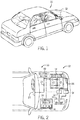
- FIG. 1 is a perspective view of an embodiment of a vehicle 10, which may utilize a regenerative braking system.
- vehicle 10 which may utilize a regenerative braking system.
- FIG. 1 is a perspective view of an embodiment of a vehicle 10, which may utilize a regenerative braking system.
- the battery system 12 may be placed in a location in the vehicle 10 that would have housed a traditional battery system.
- the vehicle 10 may include the battery system 12 positioned similarly to a lead-acid battery of a typical combustion-engine vehicle (e.g., under the hood of the vehicle 10).
- the battery system 12 may be positioned to facilitate managing temperature of the battery system 12. For example, in some embodiments, positioning a battery system 12 under the hood of the vehicle 10 may enable an air duct to channel airflow over the battery system 12 and cool the battery system 12.
- the battery system 12 includes an energy storage component 14 coupled to an ignition system 16, an alternator 18, a vehicle console 20, and optionally to an electric motor 22.
- the energy storage component 14 may capture/store electrical energy generated in the vehicle 10 and output electrical energy to power electrical devices in the vehicle 10.
- the battery system 12 may supply power to components of the vehicle's electrical system, which may include radiator cooling fans, climate control systems, electric power steering systems, active suspension systems, auto park systems, electric oil pumps, electric super/turbochargers, electric water pumps, heated windscreen/defrosters, window lift motors, vanity lights, tire pressure monitoring systems, sunroof motor controls, power seats, alarm systems, infotainment systems, navigation features, lane departure warning systems, electric parking brakes, external lights, or any combination thereof.
- the energy storage component 14 supplies power to the vehicle console 20 and the ignition system 16, which may be used to start (e.g., crank) the internal combustion engine 24.
- the energy storage component 14 may capture electrical energy generated by the alternator 18 and/or the electric motor 22.
- the alternator 18 may generate electrical energy while the internal combustion engine 24 is running. More specifically, the alternator 18 may convert the mechanical energy produced by the rotation of the internal combustion engine 24 into electrical energy. Additionally or alternatively, when the vehicle 10 includes an electric motor 22, the electric motor 22 may generate electrical energy by converting mechanical energy produced by the movement of the vehicle 10 (e.g., rotation of the wheels) into electrical energy.
- the energy storage component 14 may capture electrical energy generated by the alternator 18 and/or the electric motor 22 during regenerative braking.
- the alternator and/or the electric motor 22 are generally referred to herein as a regenerative braking system.
- the energy storage component 14 may be electrically coupled to the vehicle's electric system via a bus 26.
- the bus 26 may enable the energy storage component 14 to receive electrical energy generated by the alternator 18 and/or the electric motor 22. Additionally, the bus may enable the energy storage component 14 to output electrical energy to the ignition system 16 and/or the vehicle console 20. Accordingly, when a 12 volt battery system 12 is used, the bus 26 may carry electrical power typically between 8-18 volts.
- the energy storage component 14 may include multiple battery modules.
- the energy storage component 14 includes a lithium ion (e.g., a first) battery module 28 and a lead-acid (e.g., a second) battery module 30, which each includes one or more battery cells.
- the energy storage component 14 may include any number of battery modules.
- the lithium ion battery module 28 and lead-acid battery module 30 are depicted adjacent to one another, they may be positioned in different areas around the vehicle.
- the lead-acid battery module may be positioned in or about the interior of the vehicle 10 while the lithium ion battery module 28 may be positioned under the hood of the vehicle 10.
- the energy storage component 14 may include multiple battery modules to utilize multiple different battery chemistries.
- performance of the battery system 12 may be improved since the lithium ion battery chemistry generally has a higher coulombic efficiency and/or a higher power charge acceptance rate (e.g., higher maximum charge current or charge voltage) than the lead-acid battery chemistry. As such, the capture, storage, and/or distribution efficiency of the battery system 12 may be improved.
- the battery system 12 may additionally include a control module 32. More specifically, the control module 32 may control operations of components in the battery system 12, such as relays (e.g., switches) within energy storage component 14, the alternator 18, and/or the electric motor 22. For example, the control module 32 may regulate amount of electrical energy captured/supplied by each battery module 28 or 30 (e.g., to de-rate and re-rate the battery system 12), perform load balancing between the battery modules 28 and 30, determine a state of charge of each battery module 28 or 30, determine temperature of each battery module 28 or 30, control voltage output by the alternator 18 and/or the electric motor 22, and the like.
- the control module 32 may control operations of components in the battery system 12, such as relays (e.g., switches) within energy storage component 14, the alternator 18, and/or the electric motor 22.
- the control module 32 may regulate amount of electrical energy captured/supplied by each battery module 28 or 30 (e.g., to de-rate and re-rate the battery system 12), perform load balancing between the battery modules 28
- control unit 32 may include one or processor 34 and one or more memory 36. More specifically, the one or more processor 34 may include one or more application specific integrated circuits (ASICs), one or more field programmable gate arrays (FPGAs), one or more general purpose processors, or any combination thereof. Additionally, the one or more memory 36 may include volatile memory, such as random access memory (RAM), and/or non-volatile memory, such as read-only memory (ROM), optical drives, hard disc drives, or solid-state drives. In some embodiments, the control unit 32 may include portions of a vehicle control unit (VCU) and/or a separate battery control module.
- VCU vehicle control unit
- the lithium ion battery module 28 and the lead-acid battery module 30 are connected in parallel across their terminals, In other words, the lithium ion battery module 28 and the lead-acid module 30 may be coupled in parallel to the vehicle's electrical system via the bus 26.
- different types of the lithium ion battery module 28 may utilize components of the same type and may have similar geometrical features (e.g., layout, overall architecture).
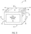
- An example embodiment of the layout of the lithium ion battery module 28 is illustrated in FIG. 3 .
- the illustrated embodiment of the lithium ion battery module 28 includes a housing 40, which is intended to represent a one-piece housing or a multi-piece housing (e.g., two-piece, three-piece, or more).
- a base 42 which may also be referred to as a bottom portion and generally defines the footprint of the lithium ion battery module 28 when placed in operation (e.g., in the xEV 10)
- sides including a left side 44 and a right side 46, and a top region or top portion 48.
- the top portion 48 is generally opposite the base 42, with the sides generally extending between the two.
- the left side 44 and right side 46 are determined, in the illustrated embodiment, with reference to a cell receptacle region 50, which may be considered to correspond to a front end 52 of the lithium ion battery module 28.
- the cell receptacle region 50 is configured to receive a plurality of battery cells (e.g., prismatic electrochemical cells) in a particular orientation.
- a back end 54 of the lithium ion battery module 28 may be considered to correspond to an end opposite the cell receptacle region 50 (and, accordingly, opposite the front end 52).
- these different sections of the lithium ion battery module 28 may have substantially the same layout and/or configuration across multiple versions, meaning that similar components (e.g., components from the same source), referred to as components of the same type, may be located in these regions. It should be noted that the battery module 28 of FIG.
- a region of the lithium ion battery module 28 of FIG, 3 is intended to represent first, second, third, fourth, and so on, regions of the housing 40 corresponding to first, second, third, fourth, and so on, respective embodiments of the battery module 28.
- the phrase "common component” or “shared component” is intended to denote a component that can be interchangeably coupled for use in a set of different types of the lithium ion battery module 28, where the component is provided from a common source.
- a source of a particular one component such as a particular relay, a particular bus bar, a particular battery cell, and so forth, may be interchangeably used in the different types of lithium ion battery modules 28 set forth herein. That is, common or shared components are interchangeable, and have dimensions to within manufacturing tolerances of their common source.
- one common layout for the different versions of the lithium ion battery module 28 may include an electrical layout 56 of the top region 48.
- the electrical layout 56 may include first and second terminal regions 58, 60, corresponding to respective locations of a first terminal and second terminal (e.g., pairs of terminals, which are shown in FIG. 4 ) of the lithium ion battery module 28, the terminals being configured to provide an electrical output of the respective lithium ion battery modules 28.
- the illustrated electrical layout 56 also includes a control board region 62 corresponding to a location of a control board (where examples of the control board are shown in FIGS, 9 and 10 ), and a relay region 64 corresponding to a location of a relay.
- regions 58, 60, 62, 64 are not only locations corresponding to these components, but also may include certain features (e.g., receptacle areas, connectors, pegs, electrical traces) that enable that particular region to interface with these components, and, in certain embodiments enable them to interface and house the components in a particular way.
- certain features e.g., receptacle areas, connectors, pegs, electrical traces
- the sides of the lithium ion battery module 28 may also be configured in this manner.
- the left and/or right sides 44, 46 located laterally with respect to the cell receptacle region 50
- the vent region 66 may include one or more features configured to interface with, for example, vent plugs, vent adapters for hose connections of a vehicle, and the like. It should be noted that the disclosed embodiments are not limited to these regions and the particular components set forth above. Rather, there may be other features, including but not limited to those described in further detail below.
- the lithium ion battery modules 28 configured in accordance with present embodiments may also include regions specifically configured to couple with other components, such as fans, fan filters, fan covers, thermal management features, and the like.
- the base 42 of the lithium ion battery module 28 generally defines its footprint. With regard to vehicle integration, this can be an important design concern in that certain sizes for the base 42 may be desired for integration into a particular vehicle due to, for example, spatial constraints, Indeed, in embodiments where the xEV 10 of FIGS. 1 and 2 is a micro-hybrid, it may be desirable for the base 42 to be a size that enables the lithium ion battery module 28 to be located relatively close to a lead acid battery, close to an alternator, etc. Thus, the lithium ion battery module 28 may be a size that enables vehicle integration, as an example, under a hood of the xEV 10, or within a cage located toward a front of the xEV 10.
- first, second, and third types of the lithium ion battery module 28 may have substantially the same base configuration (e.g., substantially the same footprint).
- FIGS. 4, 5, and 6 respectively depict a first embodiment of the lithium ion battery module 28A, a second embodiment of the lithium ion battery module 28B, and a third embodiment of the lithium ion battery module 28C.
- the base 42 may be represented by the dimensions of the portion of the battery module housing 40 that is ultimately mounted to or rests on a surface of the xEV 10 (e.g., closest to the ground/floor).
- the respective housings 40 have bases 42 each having the same dimensions.
- the base 42 may generally correspond to a length (L) and a width (W) of the lithium ion battery module 28, and the length and width of the respective bases of the first, second, and third embodiments of the lithium ion battery modules 28 may be the same, which is intended to account for manufacturing tolerances.
- the lithium ion battery modules 28 are intended to represent advanced battery modules having lithium ion electrochemical cells
- the base 42 may correspond to any one of the many group representations (e.g., Battery Council international (BCI) group numbers, Deutsche Industrie Normen (DIN codes), European Norm (EN) codes) established for traditional lead acid batteries (e.g., lead acid battery module 30).
- Each group (e.g., group number) from these established set of standards has a standard length and width for the base of the particular battery corresponding to the particular group designation.
- the secondary lithium ion battery modules described herein may or may not have dimensions that substantially match or comply with the standard dimension requirements of at least a base of a known lead acid battery standard (e.g., a BCI group, DIN code, or EN code).
- the first, second, and third embodiments of the lithium ion battery modules 28 of FIGS. 4-6 may be sized to have an H5 (DIN code) base, which is 242 mm in length by 175 mm in width.
- the H5 base is also commonly referred to as an LN2 base.
- the base 42 of the lithium ion battery modules 28 may have any length and width suitable to substantially match a particular base of a lead acid battery.
- lead acid batteries it can be difficult to conform to such standards using lithium ion electrochemical cell technologies, especially when considering that lithium ion battery modules, such as those described herein, may be associated with equipment not found in traditional lead acid batteries such as intelligent control features, thermal management features, advanced venting features, and so forth.
- the present disclosure is not limited to the bases 42 of the lithium ion battery modules 28 being the same size as a lead acid standard. Rather, the lithium ion battery modules 28 may have any size for their respective bases 42, which in certain embodiments may be the same for the different lithium ion battery modules 28.
- the length L may be a value between 150 mm and 450 mm
- the width W may be a value between 100 mm and 200 mm, where the values match for all the modular lithium ion battery modules 28.
- the lithium ion battery modules 28 of FIGS. 4-6 have aspects or features with the same configuration or layout (e.g., substantially the same base 42 or the same lateral arrangement of terminals), it should be noted that their respective heights (e.g., vertical profiles opposing respective bases of the housings) may differ, depending, for example, on their power components.
- the lithium ion battery module 28 may have a first output voltage (e.g., 12 V) and a first capacity (e.g., 10 amp hours (Ah)).
- the lithium ion battery module 28 may have a second output voltage that is the same as the first output voltage while having a second capacity greater than the first capacity (e.g., 20Ah).
- the lithium ion battery module 28 of FIG. 5 differs from the first lithium ion battery module 28 of FIG. 4 by the number of total electrochemical cells in their respective housings 40.
- the first embodiment of the lithium ion battery module 28A of FIG. 4 may include a first number (e.g., 6) of electrochemical cells electrically coupled in a serial arrangement
- the second embodiment of the lithium ion battery module 28B of FIG. 5 which has a larger capacity (e.g., twice the capacity), has a second number (e.g., 12) of the same type of electrochemical cells coupled using a combination of serial and parallel electrical connections.
- the arrangement of the electrochemical cells within the housings 40 is the primary factor that causes a respective vertical profile, or height H1 of the lithium ion battery module 28 of FIG. 4 and a vertical profile, or respective height H2 of the lithium ion battery module 28 of FIG. 5 to differ.
- its cell receptacle region 50 and, therefore, its housing 40 is configured to (e.g., sized to) receive (e.g., fit) a first number of prismatic electrochemical cells conforming to a set of manufacturing specifications
- the lithium ion battery module 28 of FIG. 5 has an embodiment of the housing 40 configured to (e.g., sized to) receive (e.g., fit) a second number of the prismatic electrochemical cells, the second number being greater than the first.
- the third embodiment of the lithium ion battery module 28C of FIG. 6 has a significantly larger vertical profile or height H3, compared to the lithium ion battery modules 28 of FIGS. 4 and 5 . This is due, at least in part, to the additional number of electrochemical cells required for the lithium ion battery module 28 to reach a higher voltage (e.g., 48 V using a third number, such as 20, of the same type of electrochemical cells connected in series). That is, the housing 40 of the third embodiment of the lithium ion battery module 28C may be configured to (e.g., sized to) receive (e.g., fit) the third number of prismatic electrochemical cells). It should be noted that the different lithium ion battery modules 28 of FIGS.
- the electrochemical cells in some embodiments may be prismatic electrochemical cells that have standardized dimensions associated with a particular tolerance.
- the lithium ion battery modules 28 described herein may be modular not only from the standpoint of their electrochemical cells and their footprint (e.g., base 42), but also from the standpoint of their architecture and common components.
- the base 42 of each lithium ion battery module 28 is located at an end that is substantially opposite a location of a set of terminals of the lithium ion battery module 28, illustrated as a first terminal 70 (e.g., a positive terminal) and a second terminal 72 (e.g., a negative terminal), which are positioned in the first and second terminal regions 58, 60, respectively.
- the terminals 70, 72 may include a single component or a set of components that are common to (e.g., of the same type and configured to be interchangeably coupled to) the different lithium ion battery modules 28. Further, in accordance with certain embodiments, the first and second terminal regions 58, 60 are specifically configured to position terminal posts 74, 76 (e.g., an end of the terminal posts) of the first and second terminals 70, 72 at substantially the same level as a top cover 78 of the first lithium ion battery module 28 of FIG. 4 , a top cover 80 of the second embodiment of the lithium ion battery module 28B of FIG.
- a top cover (e.g., top cover 78) may be configured to interchangeably cover the top portions of the lithium ion battery modules 28A and 28B of FIGS. 4 and 5 .
- venting region 66 immediately adjacent to the first terminal region 58 is the venting region 66 including a vent plug 84, which is a common component for the different lithium ion battery modules 28.
- the vent plug 84 may be configured to open a vent of the lithium ion battery module 28 after an internal portion of the housing 40 reaches a pressure threshold (e.g., as a result of a battery cell rupture).
- the first and second embodiments of the lithium ion battery modules 28 in FIGS. 4 and 5 may include additional shared components.
- the first and second embodiments of the lithium ion battery modules 28 of FIGS. 4 and 5 may include a common fan assembly 86, which may include a filter portion 88 including a fan filter, and a fan portion 90 including a fan.
- the common fan assembly 86 of the first and second embodiment of the lithium ion battery modules 28 of FIGS, 4 and 5 may also include a cover that is specifically configured (e.g., shaped and sized and having specific connection features) to couple with the respective top portions 48 of the first and second lithium ion battery modules 28 of FIGS. 4 and 5 .
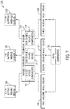
- the ability to utilize interchangeable and modular components across the different embodiments (i.e., types, versions) of the lithium ion battery modules 28 may result in the ability to manufacture the lithium ion battery modules 28 according to more efficient processes, such as performed by the embodiment of a manufacturing system 100 shown in FIG. 7 .
- Such a process may be more efficient than a traditional manufacturing process in that different types of lithium ion battery modules may be formed using shared assembly regions, shared component sources, and so forth, which may reduce capital costs and increase the speed of manufacturing.
- the shared assembly regions and shared component sources may include common components of the same type, size, and overall configuration, to within manufacturing tolerances, that can be used in any one or a combination of different types of the lithium ion battery modules (e.g., lithium ion battery modules 28 having different output voltages, different capacities, and so forth).
- the manufacturing system 100 may include the use of an initial set of shared source components 102, which may include, for example, components that can be integrated into the respective housings 40 of the different lithium ion battery modules 28.
- shared source components 102 may include, for example, components that can be integrated into the respective housings 40 of the different lithium ion battery modules 28.
- overmolded components such as terminals, structural support components, and the like, shared by the different lithium ion battery modules 28 may be incorporated into this particular portion of the system 100.
- the initial shared source components 102 may be distributed among different areas of the manufacturing system 100 where the housings 40 may be produced.
- the initial shared source components 102 e.g., common heat sinks for in-molding with housings
- the initial shared source components 102 may be distributed to a first housing mold region 104 where the housing 40 of the first embodiment of the lithium ion battery module 28A may be molded, to a second housing mold region 106 where the housing 40 of the second embodiment of the lithium ion battery module 28B may be molded, and/or to a third housing mold region 108 where the housing 40 of the third embodiment of the lithium ion battery module 28C may be molded.
- the different module housings 40 may be provided to various module component integration regions 110, where different portions of the modules are provided to the housings 40 for module completion.
- the module component integration regions 110 may include, as shown, a battery cell (electrochemical cell) shared source 112, which provides the same type of battery cell (e.g., prismatic lithium ion electrochemical cells having the same manufacturing specifications) to the different module housings 40 in their respective cell receptacle regions 50.
- Other shared source components 114 may be similarly provided, including fans, fan covers, fan filters, printed control boards, bus bars, vent plugs, and the like.
- Non-shared source components 116 provided at the regions 114 may include size-specific components, such as integrated bus bar and voltage sense carrier assemblies, certain types of relays, front covers, thermal gap pads, and the like.
- the region 110 includes a first path 124 that conveys intermediates for the first embodiment of the battery module 28A, a second path 126 that conveys intermediates for the second embodiment of the battery module 28B, and a third path 128 that conveys intermediates for the third embodiment of the battery module 28C, wherein the term "intermediates" refers to incomplete versions of the battery modules (e.g., the battery module housings 40 will some, but not all, of their respective components).
- the paths 124, 126, 128 may correspond to one or more conveyance paths, such as conveyor belts or the like, that traverse all or a portion of the region 110.
- the illustrated embodiment includes a first version of the battery module housing 130 introduced along the first path 124, a second version of the battery module housing 132 introduced along the second path 126, and a third version of the battery module housing 134 introduced along the third path 128.
- the first, second, and third versions of the battery module housing 130, 132, 134 may correspond, for example, to as-formed versions of the battery module housing 40 shown in FIGS. 4, 5, and 6 , respectively.
- the as-formed versions may be provided, for example, after molding the housings in the first, second, and third housing molding regions 104, 106, 108 of FIG. 7 .
- the paths 124, 126, 128 may converge in regions where a common component is introduced to the different modules, while they diverge in regions where size-specific or other non-shared components are introduced to the modules 28.
- the paths 124, 126, 128 convey the housings 40 to a battery cell positioning region 136 that uses the battery cell source 112.
- the battery cell positioning region 136 includes an automated system that positions battery cells in the housings 130, 132, 134 in a particular manner, for example in a specific orientation and in a specific number for the different embodiments of the battery module 28.
- the paths 124, 126, 128 may then diverge from one another to separate respective sections of a first component integration region, depicted as region 138A for path 124, region 138B for path 126, and region 138C for path 128,
- the regions 138A-138C utilize different sources of a component not shared by the different lithium ion battery modules 28, including a first version of a first non-shared component 140A for region 138A, a second version of the first non-shared component 140B for region 138B, and a third version of the first non-shared component 140C.
- the different versions of the first non-shared component may include size-specific components, such as structural supports (carriers) for integrated bus bar and voltage sense assemblies for each lithium ion battery module 28, a front cover for each lithium ion battery module 28, and the like. It should be noted that conveyance of different partial battery module assemblies on an area for shared components may be avoided in accordance with present embodiments by distributing the shared components from a common source (i.e., a source of a set of the same type of component having the same dimensions and configuration, to within manufacturing tolerances).
- a common source i.e., a source of a set of the same type of component having the same dimensions and configuration, to within manufacturing tolerances.
- the illustrated component integration region 110 may also include additional regions where common (i.e., interchangeably couplable) components are provided to the different types of the lithium ion battery module 28.
- Such embodiments are intended to be represented by a second component integration region 146 that utilizes a second shared component 148 (and/or source thereof), where the different types of the lithium ion battery module 28 may be fitted with common components, such as the same fan assemblies, the same bus bars, the same electrical connectors, and so forth.
- such modularity of the different versions of the lithium ion battery module 28 may be a result of all the lithium ion battery modules 28 having a corresponding region (e.g., a recess having a particular shape) for these different common components, including connectors, receptacles, spaces, or the like, that are specifically configured to receive the shared components.
- the component integration region 110 may include more regions where additional components, from shared or non-shared sources of these components, may be used to integrate the components with the lithium ion battery modules 28.
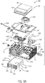
- FIGS. 9 and 10 depict exploded perspective views of the first, second, and third embodiments of the lithium ion battery module 28A, 28B, and 28C, respectively.
- FIG. 9 a comparison between the first and second lithium ion battery modules 28A, 28B demonstrates that the two modules 28 have a similar architecture, and have a number of shared components.
- the housing 40A of the first embodiment of the lithium ion battery module 28A and the housing 40B of the second embodiment of the lithium ion battery module 28B each have a layout including a plurality of regions (e.g., the terminal regions, the relay regions, and so forth).
- Each region of the plurality of regions has a particular location on the respective housings 40A, 40B, and is configured to mechanically couple to a particular component, such as control boards, relays, plugs, and so on.
- the particular locations and particular components of the plurality of regions of the first and second embodiments of the lithium ion battery modules 28A, 28B match (e.g., have the same corresponding location and the same type of component).
- the illustrated lithium ion battery modules 28A, 28B include a common electrochemical cell 160, meaning that the electrochemical cells 160 used in the different embodiments of the lithium ion battery modules 28 have the same manufacturing specifications, including the same chemistry (e.g., cathode and anode electrode active materials, electrolyte, additives) and the same size manufacturing specifications, to within a specified tolerance.
- the same chemistry e.g., cathode and anode electrode active materials, electrolyte, additives
- certain types of electrochemical cells may benefit such approaches more than others.
- the electrochemical cells 160 may have a particular combination of anode active materials (e.g., including Li 4 Ti 5 O 12 , which is lithium titanate (LTO)) and cathode active materials (e.g., including LiNi 1/3 Co 1/3 Mn 1/3 O 2 , which is nickel cobalt manganese oxide (NMC)) that prevent them from swelling beyond a predetermined threshold.
- anode active materials e.g., including Li 4 Ti 5 O 12 , which is lithium titanate (LTO)
- cathode active materials e.g., including LiNi 1/3 Co 1/3 Mn 1/3 O 2 , which is nickel cobalt manganese oxide (NMC)
- the electrochemical cells 160 have a prismatic casing 162.
- the prismatic casings 162 are subject to, and may conform to, a set of manufacturing specifications, including their size in all dimensions.
- the prismatic casings 162 include a top casing portion 164 where a set of cell terminals 166, 168 (e.g., positive and negative cell terminals) are located.
- One or more cell vents 170 may also be located on the top casing portion 164.
- the set of cell terminals 166, 168 for each of the electrochemical cells 160 enables the cells to be electrically connected to various electrical components, including each other, to the terminals 70, 72 of the lithium ion battery module 28, and a load to which the lithium ion battery module 28 may be coupled.
- the cell vents 170 are configured to enable venting of gases under certain conditions.
- the prismatic cell casings 162 also include a bottom casing portion 172 positioned opposite the top casing portion 164, first and second rounded sides 174, 176 that extend between the bottom and top casing portions 172, 164 proximate the cell terminals 166, 168, and first and second faces 178, 180 that couple the first and second rounded sides 174, 176 at opposing ends of each cell 160.
- the presently disclosed configurations may be, in some embodiments, facilitated by the presently illustrated orientation of the electrochemical cells 160 within the housings 40.
- the electrochemical cells 160 which are prismatic in FIGS. 9 and 10 , are situated in the housings 40 with their respective sets of terminals 166, 168 pointed outward from the cell receptacle regions 50.
- the electrochemical cells 160 rest on one of their two faces 178, 180 within the lithium ion battery modules 28, and the electrochemical cells are in a stacked arrangement in which the faces 178, 180 are oriented substantially parallel with respect to one another in a particular column 182 having a plurality (i.e., more than one) electrochemical cells 160.
- the electrochemical cells 160 are arranged in two such columns 182, with the number of rows depending on the number of total electrochemical cells 160.
- Such an arrangement may be desirable, for example, to maintain standard dimensions for the base 42 across the different embodiments of the lithium ion battery modules 28.
- a combination of the cell chemistry e.g., NMC/LTO electrochemical cells
- cell shape e.g., prismatic
- cell size may provide advantages that have not traditionally been used to achieve the technical effects set forth herein.
- NMC/LTO electrochemical cells may enable a total cell volume to be defined for the housing, and the remaining layout of the battery modules 28 to be defined relative to this volume.
- the terminals 70, 72 of the lithium ion battery modules 28 are all the same across the different embodiments described above with respect to FIGS. 4-6 .
- their illustrated vent configurations are also the same --- where the battery modules 28 may use the same type of closure, securement, and venting features, such as a common set of threads and screws, a common side plug 190, and a common vent opening 192 into which a common barbed fitting 194 of a corresponding size may be used to enable the vent opening 192 to be coupled to a vent hose of the xEV 10 (where the xEV is shown in FIG. 2 ).
- the first and second embodiments of the lithium ion battery module 28A, 28B may each include a respective set of common components, and the common components may represent between 60% and 95% of a total part count of the first and second embodiments of the lithium ion battery modules 28A, 28B.
- the common components may represent between 60% and 90% of the total part count, between 65% and 85% of the total part count, or between 70% and 80% of the total part count of the lithium ion battery modules 28A, 28B.
- the respective layouts of the different lithium ion battery modules 28 described herein are substantially the same.
- the relative location of the components of the different embodiments of the lithium ion battery modules 28 is the same (i.e., matching) for each module 28. This includes, for example, the regions described above with respect to FIG. 3 .
- the first and second embodiments of the lithium ion battery modules 28 include a common relay 200 configured to electrically couple and de-couple one of the terminals (e.g., the first terminal 70) to an electrical load, and a common set of electronics 202.
- the electronics 202 may include the same shape and size of circuit board, as well as the same electrical architecture (e.g., components, location, and connections) and layout. For instance, a single source of the electronics 202 is intended to be appropriately used in either the first embodiment or the second embodiment of the lithium ion battery module 28.
- the electronics 202 may include a control board, as shown, as well as various short circuit protection circuitry, a battery control module including control circuitry configured to control operational parameters of the battery modules 28, and so forth.
- the top portions 48 of the housings 40 also include the control board region 62 and the relay region 64, which are all the same layout and configuration for the first and second embodiments of the lithium ion battery module 28. That is, the control board region 62 for both the first and second embodiments of the lithium ion battery module 28 includes the same arrangement of prongs, connectors, and so forth, that enable the top portion 48 to mechanically couple to and secure the set of electronics 202.
- the relay region 64 for both the first and second embodiments of the lithium ion battery module 28 includes the same arrangement of prongs, connectors, and so forth, that enable the top portion 48 to mechanically couple to and secure the relay 200 (i.e., the same type and configuration of relay).
- the top portion 48 of the different lithium ion battery modules 28 may be the same, meaning that if the housing 40, or the portion of the housings illustrated, are formed from different pieces, the top portion 48 may be produced at a common source.
- the mold tools used to mold the housings 40 may utilize the same types of equipment, for example the same portion of the mold tool used to form the top portion 48.
- first and second embodiments of the lithium ion battery modules 28 may include a common low voltage connector 208 that may be used to electrically couple the relay 200 to certain components, for example to couple the lithium ion battery module 28 to the xEV 10, and/or to electrically couple a common fan 210 to the lithium ion battery module 28 to power the fan 210.
- the top cover 78 over which the fan 210 is disposed, is also common for the first and second embodiments of the lithium ion battery modules 28. Further, as noted above, the fan assembly 86 is also common between the two, including a fan filter 212. The manner in which a back cover 214 of the fan assembly 86 interfaces with the first and second embodiments of the lithium ion battery modules 28 may also be the same.
- the third embodiment of the lithium ion battery module 28C also includes common components as set forth above. Indeed, in addition to having the same general layout as set forth above for the first and second embodiments of the lithium ion battery module 28A, 28B, the third embodiment of the lithium ion battery module 28C also uses the same shunt bridge 204, relay bus bar 206, terminals 70, 72, side plugs 190, and barbed fittings 194, among others. As noted above, the modular aspect of the lithium ion battery modules 28 also includes the use of the common electrochemical cell 160.
- a respective relay 220 and a respective set of electronics 222 may be different for the third embodiment of the lithium ion battery module 28C compared to others, the relative layout and placement of these features on its respective top portion 48 of the housing 40 is substantially the same (i.e., matches the first and second embodiments of the lithium ion battery modules 28A-28C).
- the electronics region 62 and the relay region 64 of the third embodiment of the lithium ion battery module 28C may be different compared to the others illustrated. For example, its layout of connectors, prongs, and so forth, may be different but generally located in a matching position as set forth for modules 28A and 28B.
- One or more of the disclosed embodiments may provide one or more technical effects including the use of a number of shared components across different battery modules having different electrical characteristics.
- two or more battery modules, each having a different number of electrochemical cells may include a number of components that are provided by a common source.
- the use of such common components facilitates manufacturing and reduces associated costs by enabling faster manufacture and greater compatibility between battery modules.
- the technical effects and technical problems in the specification are exemplary and are not limiting. It should be noted that the embodiments described in the specification may have other technical effects and can solve other technical problems.
Landscapes
- Chemical & Material Sciences (AREA)
- Chemical Kinetics & Catalysis (AREA)
- Electrochemistry (AREA)
- General Chemical & Material Sciences (AREA)
- Engineering & Computer Science (AREA)
- Inorganic Chemistry (AREA)
- Manufacturing & Machinery (AREA)
- Microelectronics & Electronic Packaging (AREA)
- Materials Engineering (AREA)
- Charge And Discharge Circuits For Batteries Or The Like (AREA)
- Battery Mounting, Suspending (AREA)
- Secondary Cells (AREA)
Description
- The present disclosure relates generally to the field of batteries and battery modules. More specifically, the present disclosure relates to water management features for Lithium-ion (Li-ion) battery modules.
- This section is intended to introduce the reader to various aspects of art that may be related to various aspects of the present disclosure, which are described and/or claimed below. This discussion is believed to be helpful in providing the reader with background information to facilitate a better understanding of the various aspects of the present disclosure. Accordingly, it should be understood that these statements are to be read in this light, and not as admissions of prior art.
- A vehicle that uses one or more battery systems for providing all or a portion of the motive power for the vehicle can be referred to as an xEV, where the term "xEV" is defined herein to include all of the following vehicles, or any variations or combinations thereof, that use electric power for all or a portion of their vehicular motive force. For example, xEVs include electric vehicles (EVs) that utilize electric power for all motive force. As will be appreciated by those skilled in the art, hybrid electric vehicles (HEVs), also considered xEVs, combine an internal combustion engine propulsion system and a battery-powered electric propulsion system, such as 48 Volt (V) or 130V systems. The term HEV may include any variation of a hybrid electric vehicle. For example, full hybrid systems (FHEVs) may provide motive and other electrical power to the vehicle using one or more electric motors, using only an internal combustion engine, or using both. In contrast, mild hybrid systems (MHEVs) disable the internal combustion engine when the vehicle is idling and utilize a battery system to continue powering the air conditioning unit, radio, or other electronics, as well as to restart the engine when propulsion is desired. The mild hybrid system may also apply some level of power assist, during acceleration for example, to supplement the internal combustion engine. Mild hybrids are typically 96V to 130V and recover braking energy through a belt or crank integrated starter generator. Further, a micro-hybrid electric vehicle (mHEV) also uses a "Stop-Start" system similar to the mild hybrids, but the micro-hybrid systems of a mHEV may or may not supply power assist to the internal combustion engine and operates at a voltage below 60V. For the purposes of the present discussion, it should be noted that mHEVs typically do not technically use electric power provided directly to the crankshaft or transmission for any portion of the motive force of the vehicle, but an mHEV may still be considered as an xEV since it does use electric power to supplement a vehicle's power needs when the vehicle is idling with internal combustion engine disabled and recovers braking energy through an integrated starter generator. In addition, a plug-in electric vehicle (PEV) is any vehicle that can be charged from an external source of electricity, such as wall sockets, and the energy stored in the rechargeable battery packs drives or contributes to drive the wheels. PEVs are a subcategory of EVs that include all-electric or battery electric vehicles (BEVs), plug-in hybrid electric vehicles (PHEVs), and electric vehicle conversions of hybrid electric vehicles and conventional internal combustion engine vehicles.
- xEVs as described above may provide a number of advantages as compared to more traditional gas-powered vehicles using only internal combustion engines and traditional electrical systems, which are typically 12V systems powered by a lead acid battery. For example, xEVs may produce fewer undesirable emission products and may exhibit greater fuel efficiency as compared to traditional internal combustion vehicles and, in some cases, such xEVs may eliminate the use of gasoline entirely, as is the case of certain types of EVs or FEVs.
- As technology continues to evolve, there is a need to provide improved power sources, particularly battery modules, for such vehicles and other implementations. For example, traditional battery modules may be constructed on an individually-designed basis, meaning that each traditional battery module may be designed for a specific implementation (e.g., voltage and capacity). Accordingly, each type of traditional battery module may use components specifically selected for that module. It is now recognized that in traditional approaches, it may be difficult to construct battery modules for different applications, but using a shared approach and source of components for the modules. Indeed, it is now recognized that it may be desirable to provide battery modules that utilize a set of common (shared) components, and other shared features.
- A summary of certain embodiments disclosed herein is set forth below. It should be understood that these aspects are presented merely to provide the reader with a brief summary of these certain embodiments and that these aspects are not intended to limit the scope of this disclosure. Indeed, this disclosure may encompass a variety of aspects that may not be set forth below.
-
US2012100401 discloses a lithium ion battery product portfolio according to the preamble ofclaim 1. - Present embodiments are directed toward a series of battery modules having a plurality of electrochemical cells (which may also be referred to as battery cells herein) having different voltages and/or capacities, where the battery modules are each constructed using components, architectures, production methods, among other things, in common with each other. For example, in certain implementations of the present approach, the battery modules may include a first battery module type having a first capacity and a first voltage, a second battery module type having a second capacity and a second voltage, and, in some embodiments, additional battery module types (e.g., a third battery module type having a third capacity and a third voltage) having different voltages and/or capacities,
- For example, in one aspect, the present invention relates to a lithium ion battery module product portofolio according to the appended claims.
- In another aspect, the present disclosure also relates to a method of manufacturing lithium ion battery modules. The method includes producing a first lithium ion battery module by a first process that includes disposing a first number of prismatic electrochemical cells having a set of standardized dimensions in a first housing, the first housing having a first base with a length and a width, and electrically connecting the first number of prismatic electrochemical cells such that the first lithium ion battery module has a first voltage and a first capacity. The method also includes producing a second battery module by a second process, the second process including disposing a second number of prismatic electrochemical cells having the set of standardized dimensions in a second housing different from the first housing, the second housing having a second base with the length and the width, and electrically connecting the second number of prismatic electrochemical cells such that the second lithium ion battery module has a second voltage and a second capacity. The first process and the second process collectively comprise using a type of component configured to interchangeably couple with a first region of the first housing of the first lithium ion battery module and a second region of the housing of the second lithium ion battery module, the first and second regions having the same location on their first and second housings, respectively.
- In yet another aspect, the present disclosure also relates to a lithium ion battery module product portfolio, including a first lithium ion battery module product having a first layout. The first layout includes a first module housing configured to house a first set of electrochemical cells. The first module housing includes a first top portion having terminals configured to provide a voltage output of the first lithium ion battery module product, a first base disposed opposite the top portion and having a set of dimensions; and a first cell receptacle region disposed between the first top portion and the first base, the first cell receptacle region being configured to receive the first set of electrochemical cells in an orientation, The system also includes a second lithium ion battery module product having a second layout, the layout including a second module housing configured to house a second set of electrochemical cells, the second set of electrochemical cells having a greater number of electrochemical cells compared to the first set of electrochemical cells. The second module housing includes a second top portion having terminals configured to provide a voltage output of the second lithium ion battery module, a second base disposed opposite the second top portion and having the same set of dimensions as the first base, and a second cell receptacle region disposed between the second top portion and the second base, the second cell receptacle region being configured to receive the second set of electrochemical cells in the orientation. The system further includes a plurality of components configured to interchangeably couple with a plurality of corresponding first regions of the first battery module housing and a plurality of corresponding second regions of the second module housing, and the first and second layouts are such that the corresponding first and second regions have the same location on their respective housings.
-
-
FIG. 1 is a perspective view of an xEV having a battery system configured in accordance with present embodiments to provide power for various components of the xEV, in accordance with an aspect of the present disclosure; -
FIG. 2 is a cutaway schematic view of an embodiment of the xEV having a start-stop system that utilizes the battery system ofFIG. 1 , the battery system having a lithium ion battery module, in accordance with an aspect of the present disclosure; -
FIG. 3 is a schematic representation of a layout of an embodiment of the lithium ion battery module ofFIG. 2 , in accordance with an aspect of the present disclosure; -
FIG. 4 is a perspective view of an embodiment of the lithium ion battery module ofFIG. 2 having various components that may be used in other versions of a lithium ion battery module, in accordance with an aspect of the present disclosure; -
FIG. 5 is a perspective view of an embodiment of the lithium ion battery module ofFIG. 2 having various components that may be used in other versions of a lithium ion battery module, in accordance with an aspect of the present disclosure; -
FIG. 6 is a perspective view of an embodiment of the lithium ion battery module ofFIG. 2 having various components that may be used in other versions of a lithium ion battery module, in accordance with an aspect of the present disclosure; -
FIG. 7 is a block diagram representing an embodiment of a manufacturing system configured to produce a set of lithium ion battery modules having a plurality of common components, in accordance with an aspect of the present disclosure; -
FIG. 8 is a block diagram representing an embodiment of a region of the manufacturing system ofFIG. 7 in which various shared components may be incorporated into a variety of different lithium ion battery modules, in accordance with an aspect of the present disclosure; -
FIG. 9 (FIGS. 9A and9B ) is a combined exploded perspective view of the embodiments of the lithium ion battery modules ofFIGS. 4 and 5 and highlighting various shared components between the modules, in accordance with an aspect of the present disclosure; -
FIG. 10 (FIGS, 10A and10B ) is a combined exploded perspective view of the embodiments of the lithium ion battery modules ofFIGS. 4 and 6 and highlighting various shared components between the modules, in accordance with an aspect of the present disclosure. - One or more specific embodiments will be described below. In an effort to provide a concise description of these embodiments, not all features of an actual implementation are described in the specification. It should be appreciated that in the development of any such actual implementation, as in any engineering or design project, numerous implementation-specific decisions must be made to achieve the developers' specific goals, such as compliance with system-related and business-related constraints, which may vary from one implementation to another. Moreover, it should be appreciated that such a development effort might be complex and time consuming, but would nevertheless be a routine undertaking of design, fabrication, and manufacture for those of ordinary skill having the benefit of this disclosure.
- When introducing elements of various embodiments of the present disclosure, the articles "a," "an," and "the" are intended to mean that there are one or more of the elements. The terms "comprising," "including," and "having" are intended to be inclusive and mean that there may be additional elements other than the listed elements. Additionally, it should be understood that references to "one embodiment" or "an embodiment" of the present disclosure are not intended to be interpreted as excluding the existence of additional embodiments that also incorporate the recited features.
- The battery systems described herein may be used to provide power to various types of electric vehicles (xEVs) and other high voltage energy storage/expending applications (e.g., electrical grid power storage systems). Such battery systems may include one or more battery modules, each battery module having a housing and a number of battery cells (e.g., Lithium-ion (Li-ion) electrochemical cells) arranged within the housing to provide particular voltages and/or currents useful to power, for example, one or more components of an xEV. As another example, battery modules in accordance with present embodiments may be incorporated with or provide power to stationary power systems (e.g., non-automotive systems).
- Present embodiments are directed toward a lithium ion battery module product portfolio including a series of battery module products having a plurality of electrochemical cells (which may also be referred to as battery cells) having different electrical characteristics such as voltages and/or capacities, where the battery module products are each constructed using components, architectures, production methods, among other things, in common with each other. For example, in certain implementations of the present approach, the battery module products (also referred to herein individually as a "battery module" and collectively as "battery modules") may include a first battery module type (e.g., a first battery module product) having a first capacity and a first voltage, a second battery module type (e.g., a second battery module product) having a second capacity and a second voltage, and, in some embodiments, additional battery module types (e.g., a third battery module type or product having a third capacity and a third voltage) having different voltages and/or capacities.
- Again, the battery module types (e.g., a battery module products) may differ in voltage and/or capacity, but may have a number of similar components that may be utilized in any of the different designs in a modular fashion. For instance, these modular components may include, but are not limited to, battery cells, terminals, bus bar connections, shunt bridges, side plugs, fans, low voltage connectors, relays, printed circuit boards (PCBs), and fan filters.
- Not only are the same types of components used across the different battery module types or products, but the battery module types also include housings that, while different in terms of the number of battery cells they may hold, ultimately include features that perform the same functions in substantially the same way. That is, the different battery module types include similar design concepts for their respective housings, including similar receptacles for the similar components and, in some embodiments, a similar layout.
- Though there may be two, three, or more different battery module types depending, for example, on the number of battery cells utilized in the battery module and the manner in which they are connected, the present embodiments are described in the context of two or three battery modules (which are also battery module products as described herein). For example, two battery modules may have a similar voltage rating but different capacities, and a third battery module may have a different voltage but the same capacity as one of the other two battery modules. However, any combination of overlapping voltages and/or capacities is encompassed by the present disclosure.
- As set forth above, in certain xEV contexts (among others, such as non-automotive or stationary energy expending applications), a 12 V output from a lithium ion battery module may be desirable to power certain types of components (e.g., similar types of components traditionally powered by a traditional lead acid battery in traditional vehicles), while a 48 V output may be more suitable to power other types of components that may require a higher voltage, such as an air conditioning system. With this in mind, it is now recognized that the present battery module embodiments may be particularly applicable to such types of battery modules.
- By way of non-limiting example, the different battery modules constructed in accordance with the modular approaches described herein may include a first battery module type having a voltage of 12V and a capacity of 10 Amp hours (Ah), a second battery module type having a voltage of 12V and a capacity of 20Ah, and a third battery module type having a voltage of 48V and a capacity of 10Ah.
- To help illustrate,
FIG. 1 is a perspective view of an embodiment of avehicle 10, which may utilize a regenerative braking system. Although the following discussion is presented in relation to vehicles with regenerative braking systems, the techniques described herein are adaptable to other vehicles that capture/store electrical energy with a battery, which may include electric-powered and gas-powered vehicles. - It is now recognized that it is desirable for a non-traditional battery system 12 (e.g., a lithium ion car battery) to be largely compatible with traditional vehicle designs. In this respect, present embodiments include various types of battery modules for xEVs and systems that include xEVs. Accordingly, the
battery system 12 may be placed in a location in thevehicle 10 that would have housed a traditional battery system. For example, as illustrated, thevehicle 10 may include thebattery system 12 positioned similarly to a lead-acid battery of a typical combustion-engine vehicle (e.g., under the hood of the vehicle 10). Furthermore, as will be described in more detail below, thebattery system 12 may be positioned to facilitate managing temperature of thebattery system 12. For example, in some embodiments, positioning abattery system 12 under the hood of thevehicle 10 may enable an air duct to channel airflow over thebattery system 12 and cool thebattery system 12. - A more detailed view of the
battery system 12 is described inFIG. 2 . As depicted, thebattery system 12 includes anenergy storage component 14 coupled to anignition system 16, analternator 18, avehicle console 20, and optionally to anelectric motor 22. Generally, theenergy storage component 14 may capture/store electrical energy generated in thevehicle 10 and output electrical energy to power electrical devices in thevehicle 10. - In other words, the
battery system 12 may supply power to components of the vehicle's electrical system, which may include radiator cooling fans, climate control systems, electric power steering systems, active suspension systems, auto park systems, electric oil pumps, electric super/turbochargers, electric water pumps, heated windscreen/defrosters, window lift motors, vanity lights, tire pressure monitoring systems, sunroof motor controls, power seats, alarm systems, infotainment systems, navigation features, lane departure warning systems, electric parking brakes, external lights, or any combination thereof. Illustratively, in the depicted embodiment, theenergy storage component 14 supplies power to thevehicle console 20 and theignition system 16, which may be used to start (e.g., crank) theinternal combustion engine 24. - Additionally, the
energy storage component 14 may capture electrical energy generated by thealternator 18 and/or theelectric motor 22. In some embodiments, thealternator 18 may generate electrical energy while theinternal combustion engine 24 is running. More specifically, thealternator 18 may convert the mechanical energy produced by the rotation of theinternal combustion engine 24 into electrical energy. Additionally or alternatively, when thevehicle 10 includes anelectric motor 22, theelectric motor 22 may generate electrical energy by converting mechanical energy produced by the movement of the vehicle 10 (e.g., rotation of the wheels) into electrical energy. Thus, in some embodiments, theenergy storage component 14 may capture electrical energy generated by thealternator 18 and/or theelectric motor 22 during regenerative braking. As such, the alternator and/or theelectric motor 22 are generally referred to herein as a regenerative braking system. - To facilitate capturing and supplying electric energy, the
energy storage component 14 may be electrically coupled to the vehicle's electric system via abus 26. For example, thebus 26 may enable theenergy storage component 14 to receive electrical energy generated by thealternator 18 and/or theelectric motor 22. Additionally, the bus may enable theenergy storage component 14 to output electrical energy to theignition system 16 and/or thevehicle console 20. Accordingly, when a 12volt battery system 12 is used, thebus 26 may carry electrical power typically between 8-18 volts. - Additionally, as depicted, the
energy storage component 14 may include multiple battery modules. For example, in the depicted embodiment, theenergy storage component 14 includes a lithium ion (e.g., a first)battery module 28 and a lead-acid (e.g., a second)battery module 30, which each includes one or more battery cells. In other embodiments, theenergy storage component 14 may include any number of battery modules. Additionally, although the lithiumion battery module 28 and lead-acid battery module 30 are depicted adjacent to one another, they may be positioned in different areas around the vehicle. For example, the lead-acid battery module may be positioned in or about the interior of thevehicle 10 while the lithiumion battery module 28 may be positioned under the hood of thevehicle 10. - In some embodiments, the
energy storage component 14 may include multiple battery modules to utilize multiple different battery chemistries. For example, when the lithiumion battery module 28 is used, performance of thebattery system 12 may be improved since the lithium ion battery chemistry generally has a higher coulombic efficiency and/or a higher power charge acceptance rate (e.g., higher maximum charge current or charge voltage) than the lead-acid battery chemistry. As such, the capture, storage, and/or distribution efficiency of thebattery system 12 may be improved. - To facilitate controlling the capturing and storing of electrical energy, the
battery system 12 may additionally include acontrol module 32. More specifically, thecontrol module 32 may control operations of components in thebattery system 12, such as relays (e.g., switches) withinenergy storage component 14, thealternator 18, and/or theelectric motor 22. For example, thecontrol module 32 may regulate amount of electrical energy captured/supplied by eachbattery module 28 or 30 (e.g., to de-rate and re-rate the battery system 12), perform load balancing between thebattery modules battery module battery module alternator 18 and/or theelectric motor 22, and the like. - Accordingly, the
control unit 32 may include one orprocessor 34 and one ormore memory 36. More specifically, the one ormore processor 34 may include one or more application specific integrated circuits (ASICs), one or more field programmable gate arrays (FPGAs), one or more general purpose processors, or any combination thereof. Additionally, the one ormore memory 36 may include volatile memory, such as random access memory (RAM), and/or non-volatile memory, such as read-only memory (ROM), optical drives, hard disc drives, or solid-state drives. In some embodiments, thecontrol unit 32 may include portions of a vehicle control unit (VCU) and/or a separate battery control module. Furthermore, as depicted, the lithiumion battery module 28 and the lead-acid battery module 30 are connected in parallel across their terminals, In other words, the lithiumion battery module 28 and the lead-acid module 30 may be coupled in parallel to the vehicle's electrical system via thebus 26. - It should be noted that presently disclosed embodiments may be applicable to any battery module having the same or different configurations and/or orientations described above and in detail below. One of ordinary skill in the art would recognize that the components and examples used to describe battery modules in accordance with the present disclosure should not be construed to limit the present disclosure to those components and examples alone. Rather, the disclosed examples are merely intended to serve as non-limiting examples to facilitate discussion of the present disclosure.
- As set forth above, in accordance with the present disclosure, different types of the lithium ion battery module 28 (e.g., a lithium ion battery module product portfolio including different lithium ion battery module products) may utilize components of the same type and may have similar geometrical features (e.g., layout, overall architecture). An example embodiment of the layout of the lithium
ion battery module 28 is illustrated inFIG. 3 . Specifically, the illustrated embodiment of the lithiumion battery module 28 includes ahousing 40, which is intended to represent a one-piece housing or a multi-piece housing (e.g., two-piece, three-piece, or more). To facilitate discussion, different sections of the housing 40 (which may or may not correspond to sections of the overall lithium ion battery module 28) may be defined as follows: a base 42, which may also be referred to as a bottom portion and generally defines the footprint of the lithiumion battery module 28 when placed in operation (e.g., in the xEV 10), sides including aleft side 44 and aright side 46, and a top region ortop portion 48. Thetop portion 48 is generally opposite thebase 42, with the sides generally extending between the two. Theleft side 44 andright side 46 are determined, in the illustrated embodiment, with reference to acell receptacle region 50, which may be considered to correspond to afront end 52 of the lithiumion battery module 28. As described in further detail below, thecell receptacle region 50 is configured to receive a plurality of battery cells (e.g., prismatic electrochemical cells) in a particular orientation. Aback end 54 of the lithiumion battery module 28 may be considered to correspond to an end opposite the cell receptacle region 50 (and, accordingly, opposite the front end 52). In accordance with present embodiments, these different sections of the lithiumion battery module 28 may have substantially the same layout and/or configuration across multiple versions, meaning that similar components (e.g., components from the same source), referred to as components of the same type, may be located in these regions. It should be noted that thebattery module 28 ofFIG. 3 is intended to represent multiple versions (e.g., individual products of a product portfolio), also referred to as embodiments or types, of lithium ion battery modules having the same regions located in the same (e.g., corresponding from a location standpoint) portion of the battery module relative to all other features of the battery module. For example, a region of the lithiumion battery module 28 ofFIG, 3 is intended to represent first, second, third, fourth, and so on, regions of thehousing 40 corresponding to first, second, third, fourth, and so on, respective embodiments of thebattery module 28. - In accordance with the present disclosure, the phrase "common component" or "shared component" is intended to denote a component that can be interchangeably coupled for use in a set of different types of the lithium
ion battery module 28, where the component is provided from a common source. For instance, a source of a particular one component such as a particular relay, a particular bus bar, a particular battery cell, and so forth, may be interchangeably used in the different types of lithiumion battery modules 28 set forth herein. That is, common or shared components are interchangeable, and have dimensions to within manufacturing tolerances of their common source. - In accordance with an aspect of the present disclosure, one common layout for the different versions of the lithium
ion battery module 28 may include anelectrical layout 56 of thetop region 48. For example, theelectrical layout 56, as illustrated, may include first and secondterminal regions FIG. 4 ) of the lithiumion battery module 28, the terminals being configured to provide an electrical output of the respective lithiumion battery modules 28. The illustratedelectrical layout 56 also includes acontrol board region 62 corresponding to a location of a control board (where examples of the control board are shown inFIGS, 9 and10 ), and arelay region 64 corresponding to a location of a relay. Examples of the relay are shown inFIGS. 9 and10 . It should be noted that theregions - The sides of the lithium ion battery module 28 (e.g., the housing 40) may also be configured in this manner. For example, the left and/or
right sides 44, 46 (located laterally with respect to the cell receptacle region 50) may include avent region 66, corresponding to a location where gases may be vented out of themodule 14. Thevent region 66 may include one or more features configured to interface with, for example, vent plugs, vent adapters for hose connections of a vehicle, and the like. It should be noted that the disclosed embodiments are not limited to these regions and the particular components set forth above. Rather, there may be other features, including but not limited to those described in further detail below. For example, the lithiumion battery modules 28 configured in accordance with present embodiments may also include regions specifically configured to couple with other components, such as fans, fan filters, fan covers, thermal management features, and the like. - As set forth above, the
base 42 of the lithiumion battery module 28 generally defines its footprint. With regard to vehicle integration, this can be an important design concern in that certain sizes for the base 42 may be desired for integration into a particular vehicle due to, for example, spatial constraints, Indeed, in embodiments where thexEV 10 ofFIGS. 1 and 2 is a micro-hybrid, it may be desirable for the base 42 to be a size that enables the lithiumion battery module 28 to be located relatively close to a lead acid battery, close to an alternator, etc. Thus, the lithiumion battery module 28 may be a size that enables vehicle integration, as an example, under a hood of thexEV 10, or within a cage located toward a front of thexEV 10. - With this in mind, one aspect of the present disclosure provides embodiments in which first, second, and third types of the lithium
ion battery module 28 may have substantially the same base configuration (e.g., substantially the same footprint). This aspect may be further appreciated with reference toFIGS. 4, 5, and 6 , which respectively depict a first embodiment of the lithiumion battery module 28A, a second embodiment of the lithiumion battery module 28B, and a third embodiment of the lithiumion battery module 28C. Again, thebase 42 may be represented by the dimensions of the portion of thebattery module housing 40 that is ultimately mounted to or rests on a surface of the xEV 10 (e.g., closest to the ground/floor). In accordance with an embodiment, therespective housings 40 havebases 42 each having the same dimensions. - The base 42 may generally correspond to a length (L) and a width (W) of the lithium
ion battery module 28, and the length and width of the respective bases of the first, second, and third embodiments of the lithiumion battery modules 28 may be the same, which is intended to account for manufacturing tolerances. Further, although the lithiumion battery modules 28 are intended to represent advanced battery modules having lithium ion electrochemical cells, thebase 42 may correspond to any one of the many group representations (e.g., Battery Council international (BCI) group numbers, Deutsche Industrie Normen (DIN codes), European Norm (EN) codes) established for traditional lead acid batteries (e.g., lead acid battery module 30). Each group (e.g., group number) from these established set of standards has a standard length and width for the base of the particular battery corresponding to the particular group designation. The secondary lithium ion battery modules described herein may or may not have dimensions that substantially match or comply with the standard dimension requirements of at least a base of a known lead acid battery standard (e.g., a BCI group, DIN code, or EN code). - As one example, the first, second, and third embodiments of the lithium
ion battery modules 28 ofFIGS. 4-6 may be sized to have an H5 (DIN code) base, which is 242 mm in length by 175 mm in width. The H5 base is also commonly referred to as an LN2 base. However, thebase 42 of the lithiumion battery modules 28 may have any length and width suitable to substantially match a particular base of a lead acid battery. Although standardized for lead acid batteries, it can be difficult to conform to such standards using lithium ion electrochemical cell technologies, especially when considering that lithium ion battery modules, such as those described herein, may be associated with equipment not found in traditional lead acid batteries such as intelligent control features, thermal management features, advanced venting features, and so forth. However, the present disclosure is not limited to thebases 42 of the lithiumion battery modules 28 being the same size as a lead acid standard. Rather, the lithiumion battery modules 28 may have any size for theirrespective bases 42, which in certain embodiments may be the same for the different lithiumion battery modules 28. As a non-limiting example, the length L may be a value between 150 mm and 450 mm, and the width W may be a value between 100 mm and 200 mm, where the values match for all the modular lithiumion battery modules 28. - While the lithium
ion battery modules 28 ofFIGS. 4-6 have aspects or features with the same configuration or layout (e.g., substantially thesame base 42 or the same lateral arrangement of terminals), it should be noted that their respective heights (e.g., vertical profiles opposing respective bases of the housings) may differ, depending, for example, on their power components. For example, inFIG. 4 , the lithiumion battery module 28 may have a first output voltage (e.g., 12 V) and a first capacity (e.g., 10 amp hours (Ah)). InFIG. 5 , the lithiumion battery module 28 may have a second output voltage that is the same as the first output voltage while having a second capacity greater than the first capacity (e.g., 20Ah). From a power component standpoint, the lithiumion battery module 28 ofFIG. 5 differs from the first lithiumion battery module 28 ofFIG. 4 by the number of total electrochemical cells in theirrespective housings 40. In one embodiment, the first embodiment of the lithiumion battery module 28A ofFIG. 4 may include a first number (e.g., 6) of electrochemical cells electrically coupled in a serial arrangement, while the second embodiment of the lithiumion battery module 28B ofFIG. 5 , which has a larger capacity (e.g., twice the capacity), has a second number (e.g., 12) of the same type of electrochemical cells coupled using a combination of serial and parallel electrical connections. The arrangement of the electrochemical cells within thehousings 40, which is described in further detail below, is the primary factor that causes a respective vertical profile, or height H1 of the lithiumion battery module 28 ofFIG. 4 and a vertical profile, or respective height H2 of the lithiumion battery module 28 ofFIG. 5 to differ. For the lithiumion battery module 28 inFIG, 4 , itscell receptacle region 50 and, therefore, itshousing 40, is configured to (e.g., sized to) receive (e.g., fit) a first number of prismatic electrochemical cells conforming to a set of manufacturing specifications, while the lithiumion battery module 28 ofFIG. 5 has an embodiment of thehousing 40 configured to (e.g., sized to) receive (e.g., fit) a second number of the prismatic electrochemical cells, the second number being greater than the first. - The third embodiment of the lithium
ion battery module 28C ofFIG. 6 has a significantly larger vertical profile or height H3, compared to the lithiumion battery modules 28 ofFIGS. 4 and 5 . This is due, at least in part, to the additional number of electrochemical cells required for the lithiumion battery module 28 to reach a higher voltage (e.g., 48 V using a third number, such as 20, of the same type of electrochemical cells connected in series). That is, thehousing 40 of the third embodiment of the lithiumion battery module 28C may be configured to (e.g., sized to) receive (e.g., fit) the third number of prismatic electrochemical cells). It should be noted that the different lithiumion battery modules 28 ofFIGS. 4-6 all utilize lithium ion electrochemical cells having standardized dimensions, which are dimensions that are intended to be produced for a particular electrochemical cell type, and is intended to allow for manufacturing tolerances. For instance, the electrochemical cells in some embodiments may be prismatic electrochemical cells that have standardized dimensions associated with a particular tolerance. - As will be appreciated from the present disclosure, the lithium
ion battery modules 28 described herein may be modular not only from the standpoint of their electrochemical cells and their footprint (e.g., base 42), but also from the standpoint of their architecture and common components. For instance, thebase 42 of each lithiumion battery module 28 is located at an end that is substantially opposite a location of a set of terminals of the lithiumion battery module 28, illustrated as a first terminal 70 (e.g., a positive terminal) and a second terminal 72 (e.g., a negative terminal), which are positioned in the first and secondterminal regions terminals ion battery modules 28. Further, in accordance with certain embodiments, the first and secondterminal regions second terminals top cover 78 of the first lithiumion battery module 28 ofFIG. 4 , atop cover 80 of the second embodiment of the lithiumion battery module 28B ofFIG. 5 (which may be the same as the top cover 78), and atop cover 82 of the third embodiment of the lithiumion battery module 28C ofFIG. 6 . In this regard, the terminal posts 74, 76 may not protrude beyond an outer surface of the lithiumion battery modules 28, which may reduce the likelihood that theterminals ion battery modules 28. Theterminal regions ion battery modules 28, in terms of volume or any one of a length, width, height, or any combination thereof, to within manufacturing tolerances. In certain embodiments, a top cover (e.g., top cover 78) may be configured to interchangeably cover the top portions of the lithiumion battery modules FIGS. 4 and 5 . - In the illustrated embodiments of
FIGS. 4-6 , immediately adjacent to the firstterminal region 58 is the ventingregion 66 including avent plug 84, which is a common component for the different lithiumion battery modules 28. The vent plug 84 may be configured to open a vent of the lithiumion battery module 28 after an internal portion of thehousing 40 reaches a pressure threshold (e.g., as a result of a battery cell rupture). - The first and second embodiments of the lithium
ion battery modules 28 inFIGS. 4 and 5 , respectively, may include additional shared components. For example, the first and second embodiments of the lithiumion battery modules 28 ofFIGS. 4 and 5 , respectively, may include acommon fan assembly 86, which may include afilter portion 88 including a fan filter, and afan portion 90 including a fan. Thecommon fan assembly 86 of the first and second embodiment of the lithiumion battery modules 28 ofFIGS, 4 and 5 may also include a cover that is specifically configured (e.g., shaped and sized and having specific connection features) to couple with the respectivetop portions 48 of the first and second lithiumion battery modules 28 ofFIGS. 4 and 5 . - It is now recognized that the ability to utilize interchangeable and modular components across the different embodiments (i.e., types, versions) of the lithium
ion battery modules 28 may result in the ability to manufacture the lithiumion battery modules 28 according to more efficient processes, such as performed by the embodiment of amanufacturing system 100 shown inFIG. 7 . Such a process may be more efficient than a traditional manufacturing process in that different types of lithium ion battery modules may be formed using shared assembly regions, shared component sources, and so forth, which may reduce capital costs and increase the speed of manufacturing. The shared assembly regions and shared component sources may include common components of the same type, size, and overall configuration, to within manufacturing tolerances, that can be used in any one or a combination of different types of the lithium ion battery modules (e.g., lithiumion battery modules 28 having different output voltages, different capacities, and so forth). - As depicted, the
manufacturing system 100 may include the use of an initial set of sharedsource components 102, which may include, for example, components that can be integrated into therespective housings 40 of the different lithiumion battery modules 28. For example, overmolded components such as terminals, structural support components, and the like, shared by the different lithiumion battery modules 28 may be incorporated into this particular portion of thesystem 100. - The initial shared
source components 102 may be distributed among different areas of themanufacturing system 100 where thehousings 40 may be produced. For example, the initial shared source components 102 (e.g., common heat sinks for in-molding with housings) may be distributed to a firsthousing mold region 104 where thehousing 40 of the first embodiment of the lithiumion battery module 28A may be molded, to a secondhousing mold region 106 where thehousing 40 of the second embodiment of the lithiumion battery module 28B may be molded, and/or to a thirdhousing mold region 108 where thehousing 40 of the third embodiment of the lithiumion battery module 28C may be molded. From these regions, thedifferent module housings 40 may be provided to various modulecomponent integration regions 110, where different portions of the modules are provided to thehousings 40 for module completion. - The module
component integration regions 110 may include, as shown, a battery cell (electrochemical cell) sharedsource 112, which provides the same type of battery cell (e.g., prismatic lithium ion electrochemical cells having the same manufacturing specifications) to thedifferent module housings 40 in their respectivecell receptacle regions 50. Other sharedsource components 114 may be similarly provided, including fans, fan covers, fan filters, printed control boards, bus bars, vent plugs, and the like.Non-shared source components 116 provided at theregions 114 may include size-specific components, such as integrated bus bar and voltage sense carrier assemblies, certain types of relays, front covers, thermal gap pads, and the like. As a result of the integration of these various components into the threedifferent housings 40, the first, second, and third embodiments of the lithiumion battery module 28, for example corresponding to themodules 28A-28C, respectively, are produced. - An example embodiment of the
component integration region 110 is depicted inFIG. 8 . As shown, theregion 110 includes afirst path 124 that conveys intermediates for the first embodiment of thebattery module 28A, asecond path 126 that conveys intermediates for the second embodiment of thebattery module 28B, and athird path 128 that conveys intermediates for the third embodiment of thebattery module 28C, wherein the term "intermediates" refers to incomplete versions of the battery modules (e.g., thebattery module housings 40 will some, but not all, of their respective components). As an example, thepaths region 110. - The illustrated embodiment includes a first version of the
battery module housing 130 introduced along thefirst path 124, a second version of thebattery module housing 132 introduced along thesecond path 126, and a third version of the battery module housing 134 introduced along thethird path 128. The first, second, and third versions of thebattery module housing battery module housing 40 shown inFIGS. 4, 5, and 6 , respectively. The as-formed versions may be provided, for example, after molding the housings in the first, second, and thirdhousing molding regions FIG. 7 . - In the
component integration region 110 of thesystem 100, thepaths modules 28. For example, as shown, thepaths housings 40 to a batterycell positioning region 136 that uses thebattery cell source 112. The batterycell positioning region 136, in certain embodiments, includes an automated system that positions battery cells in thehousings battery module 28. - The
paths region 138A forpath 124,region 138B forpath 126, andregion 138C forpath 128, Theregions 138A-138C utilize different sources of a component not shared by the different lithiumion battery modules 28, including a first version of a firstnon-shared component 140A forregion 138A, a second version of the firstnon-shared component 140B forregion 138B, and a third version of the firstnon-shared component 140C. As an example, the different versions of the first non-shared component may include size-specific components, such as structural supports (carriers) for integrated bus bar and voltage sense assemblies for each lithiumion battery module 28, a front cover for each lithiumion battery module 28, and the like. It should be noted that conveyance of different partial battery module assemblies on an area for shared components may be avoided in accordance with present embodiments by distributing the shared components from a common source (i.e., a source of a set of the same type of component having the same dimensions and configuration, to within manufacturing tolerances). - The illustrated
component integration region 110 may also include additional regions where common (i.e., interchangeably couplable) components are provided to the different types of the lithiumion battery module 28. Such embodiments are intended to be represented by a secondcomponent integration region 146 that utilizes a second shared component 148 (and/or source thereof), where the different types of the lithiumion battery module 28 may be fitted with common components, such as the same fan assemblies, the same bus bars, the same electrical connectors, and so forth. It should be noted that such modularity of the different versions of the lithiumion battery module 28 may be a result of all the lithiumion battery modules 28 having a corresponding region (e.g., a recess having a particular shape) for these different common components, including connectors, receptacles, spaces, or the like, that are specifically configured to receive the shared components. Further, thecomponent integration region 110 may include more regions where additional components, from shared or non-shared sources of these components, may be used to integrate the components with the lithiumion battery modules 28. - The modular aspect of the lithium
ion battery modules 28 described herein may be further appreciated with respect toFIGS. 9 and10 , which depict exploded perspective views of the first, second, and third embodiments of the lithiumion battery module FIG. 9 , a comparison between the first and second lithiumion battery modules modules 28 have a similar architecture, and have a number of shared components. - Starting from their
respective housings FIGS. 4 and 5 ) of the two are different, they actually have a very similar configuration. For example, thehousing 40A of the first embodiment of the lithiumion battery module 28A and thehousing 40B of the second embodiment of the lithiumion battery module 28B each have a layout including a plurality of regions (e.g., the terminal regions, the relay regions, and so forth). Each region of the plurality of regions has a particular location on therespective housings ion battery modules - For instance, the illustrated lithium
ion battery modules electrochemical cell 160, meaning that theelectrochemical cells 160 used in the different embodiments of the lithiumion battery modules 28 have the same manufacturing specifications, including the same chemistry (e.g., cathode and anode electrode active materials, electrolyte, additives) and the same size manufacturing specifications, to within a specified tolerance. In accordance with an aspect of the present disclosure, it is now recognized that certain types of electrochemical cells may benefit such approaches more than others. For example, in one embodiment, theelectrochemical cells 160 may have a particular combination of anode active materials (e.g., including Li4Ti5O12, which is lithium titanate (LTO)) and cathode active materials (e.g., including LiNi1/3Co1/3Mn1/3O2, which is nickel cobalt manganese oxide (NMC)) that prevent them from swelling beyond a predetermined threshold. For example, in the illustrated embodiments, theelectrochemical cells 160 have aprismatic casing 162. Theprismatic casings 162 are subject to, and may conform to, a set of manufacturing specifications, including their size in all dimensions. - The
prismatic casings 162 include atop casing portion 164 where a set ofcell terminals 166, 168 (e.g., positive and negative cell terminals) are located. One or more cell vents 170 may also be located on thetop casing portion 164. The set ofcell terminals electrochemical cells 160 enables the cells to be electrically connected to various electrical components, including each other, to theterminals ion battery module 28, and a load to which the lithiumion battery module 28 may be coupled. The cell vents 170 are configured to enable venting of gases under certain conditions. - The
prismatic cell casings 162 also include abottom casing portion 172 positioned opposite thetop casing portion 164, first and secondrounded sides top casing portions cell terminals second faces rounded sides cell 160. The presently disclosed configurations may be, in some embodiments, facilitated by the presently illustrated orientation of theelectrochemical cells 160 within thehousings 40. Specifically, theelectrochemical cells 160, which are prismatic inFIGS. 9 and10 , are situated in thehousings 40 with their respective sets ofterminals cell receptacle regions 50. Further, theelectrochemical cells 160 rest on one of their twofaces ion battery modules 28, and the electrochemical cells are in a stacked arrangement in which thefaces electrochemical cells 160. In the embodiments illustrated inFIGS. 9 and10 , theelectrochemical cells 160 are arranged in two such columns 182, with the number of rows depending on the number of totalelectrochemical cells 160. - Such an arrangement may be desirable, for example, to maintain standard dimensions for the
base 42 across the different embodiments of the lithiumion battery modules 28. Indeed, it is now recognized that a combination of the cell chemistry (e.g., NMC/LTO electrochemical cells), cell shape (e.g., prismatic), and cell size may provide advantages that have not traditionally been used to achieve the technical effects set forth herein. For example, it is now recognized that NMC/LTO electrochemical cells may enable a total cell volume to be defined for the housing, and the remaining layout of thebattery modules 28 to be defined relative to this volume. - As noted above, the
terminals ion battery modules 28 are all the same across the different embodiments described above with respect toFIGS. 4-6 . In addition, their illustrated vent configurations are also the same --- where thebattery modules 28 may use the same type of closure, securement, and venting features, such as a common set of threads and screws, acommon side plug 190, and acommon vent opening 192 into which a commonbarbed fitting 194 of a corresponding size may be used to enable the vent opening 192 to be coupled to a vent hose of the xEV 10 (where the xEV is shown inFIG. 2 ). As an example, the first and second embodiments of the lithiumion battery module ion battery modules ion battery modules - Further, it should be noted that the respective layouts of the different lithium
ion battery modules 28 described herein are substantially the same. For example, the relative location of the components of the different embodiments of the lithiumion battery modules 28 is the same (i.e., matching) for eachmodule 28. This includes, for example, the regions described above with respect toFIG. 3 . - With respect to their electrical components, the first and second embodiments of the lithium
ion battery modules 28 include acommon relay 200 configured to electrically couple and de-couple one of the terminals (e.g., the first terminal 70) to an electrical load, and a common set ofelectronics 202. Theelectronics 202 may include the same shape and size of circuit board, as well as the same electrical architecture (e.g., components, location, and connections) and layout. For instance, a single source of theelectronics 202 is intended to be appropriately used in either the first embodiment or the second embodiment of the lithiumion battery module 28. Theelectronics 202 may include a control board, as shown, as well as various short circuit protection circuitry, a battery control module including control circuitry configured to control operational parameters of thebattery modules 28, and so forth. - The modularity of the present approaches is reflected in the different regions of the
housings 40, as well. For instance, thetop portions 48 of thehousings 40 also include thecontrol board region 62 and therelay region 64, which are all the same layout and configuration for the first and second embodiments of the lithiumion battery module 28. That is, thecontrol board region 62 for both the first and second embodiments of the lithiumion battery module 28 includes the same arrangement of prongs, connectors, and so forth, that enable thetop portion 48 to mechanically couple to and secure the set ofelectronics 202. In addition, therelay region 64 for both the first and second embodiments of the lithiumion battery module 28 includes the same arrangement of prongs, connectors, and so forth, that enable thetop portion 48 to mechanically couple to and secure the relay 200 (i.e., the same type and configuration of relay). It should be noted that such common configurations may enhance manufacturing capability, even for different housing molds. For example, thetop portion 48 of the different lithiumion battery modules 28 may be the same, meaning that if thehousing 40, or the portion of the housings illustrated, are formed from different pieces, thetop portion 48 may be produced at a common source. Further, in embodiments where thehousings 40 are one-piece molded units, then the mold tools used to mold thehousings 40 may utilize the same types of equipment, for example the same portion of the mold tool used to form thetop portion 48. - Other illustrated and common electrical components include shunt bridges 204 and relay bus bars 206. Indeed, various other connectors and features may also be common to two or more of the lithium
ion battery modules 28. For example, the first and second embodiments of the lithiumion battery modules 28 may include a commonlow voltage connector 208 that may be used to electrically couple therelay 200 to certain components, for example to couple the lithiumion battery module 28 to thexEV 10, and/or to electrically couple acommon fan 210 to the lithiumion battery module 28 to power thefan 210. - The
top cover 78, over which thefan 210 is disposed, is also common for the first and second embodiments of the lithiumion battery modules 28. Further, as noted above, thefan assembly 86 is also common between the two, including a fan filter 212. The manner in which a back cover 214 of thefan assembly 86 interfaces with the first and second embodiments of the lithiumion battery modules 28 may also be the same. - The third embodiment of the lithium
ion battery module 28C, as shown inFIG. 10 , also includes common components as set forth above. Indeed, in addition to having the same general layout as set forth above for the first and second embodiments of the lithiumion battery module ion battery module 28C also uses thesame shunt bridge 204,relay bus bar 206,terminals barbed fittings 194, among others. As noted above, the modular aspect of the lithiumion battery modules 28 also includes the use of the commonelectrochemical cell 160. - Furthermore, while a
respective relay 220 and a respective set ofelectronics 222 may be different for the third embodiment of the lithiumion battery module 28C compared to others, the relative layout and placement of these features on its respectivetop portion 48 of thehousing 40 is substantially the same (i.e., matches the first and second embodiments of the lithiumion battery modules 28A-28C). Furthermore, because these components are different, theelectronics region 62 and therelay region 64 of the third embodiment of the lithiumion battery module 28C may be different compared to the others illustrated. For example, its layout of connectors, prongs, and so forth, may be different but generally located in a matching position as set forth formodules - One or more of the disclosed embodiments, alone or on combination, may provide one or more technical effects including the use of a number of shared components across different battery modules having different electrical characteristics. For example, two or more battery modules, each having a different number of electrochemical cells, may include a number of components that are provided by a common source. The use of such common components facilitates manufacturing and reduces associated costs by enabling faster manufacture and greater compatibility between battery modules. The technical effects and technical problems in the specification are exemplary and are not limiting. It should be noted that the embodiments described in the specification may have other technical effects and can solve other technical problems.
- While only certain features and embodiments have been illustrated and described, many modifications and changes may occur to those skilled in the art (e.g., variations in sizes, dimensions, structures, shapes and proportions of the various elements, values of parameters (e.g., temperatures, pressures, etc.), mounting arrangements, use of materials, colors, orientations, etc.) without materially departing from the scope of the appended claims. The order or sequence of any process or method steps may be varied or re-sequenced according to alternative embodiments. It is, therefore, to be understood that the appended claims are intended to cover all such modifications and changes. Furthermore, in an effort to provide a concise description of the exemplary embodiments, all features of an actual implementation may not have been described. It should be appreciated that in the development of any such actual implementation, as in any engineering or design project, numerous implementation specific decisions may be made. Such a development effort might be complex and time consuming, but would nevertheless be a routine undertaking of design, fabrication, and manufacture for those of ordinary skill having the benefit of this disclosure, without undue experimentation.
Claims (14)
- A lithium ion battery module product portfolio, comprising:- a first lithium ion battery module product (28A) comprising a first housing (40A) configured to receive a first set of prismatic electrochemical cells (160), the housing (40) including a base (42) having a first footprint;- a second lithium ion battery module product (28B) comprising a second housing (40B) configured to receive a second set of prismatic electrochemical cells (160), the second housing (40B) including a base (42) having a second footprint that is substantially the same as the first footprint, wherein a height (H1, H2) of the first and second housings (40A, 40B) is different for each of the first and second lithium ion battery module products (28A, 28B);- each prismatic electrochemical cell (160) of the first and second sets of prismatic electrochemical cells (160) conforming to the same manufacturing specifications including the same chemistry and the same size manufacturing specification, wherein the first housing (40A) of the first lithium ion battery module product (28A) is sized to fit a first number of the prismatic electrochemical cells (160), the second housing (40B) of the second lithium ion battery module product (28B) is sized to fit a second number of the prismatic electrochemical cells (160), and the first and second numbers of the prismatic lithium ion electrochemical cells (160) are different; and characterized by- a component configured to interchangeably couple with a first region of the first housing (40A) of the first lithium ion battery module product (28A) and a second region of the second housing (40B) of the second lithium ion battery module product (28B), the first and second regions having corresponding locations on the first and second housings (40A, 40B);wherein the first and second housings (40A, 40B) each comprise a pair of terminal regions (58, 60) and a pair of terminals (70, 72) located in the pair of terminal regions (58, 60), the respective pairs of terminal regions (58, 60) of the first lithium ion battery module product (28A) and the second lithium ion battery module product (28B) have the same size and are located in corresponding locations on the respective first and second housings (40A, 40B).
- The lithium ion battery module product portfolio of claim 1,
wherein the component is a relay configured to interchangeably couple with both of the first and second lithium ion battery module products (28A, 28B), wherein the first region comprises a first relay region and the second region comprises a second relay region, and the first and second relay regions each comprises a set of connectors configured to mechanically couple to the relay. - The lithium ion battery module product portfolio of claim 1,
wherein the component is a control board having control circuitry configured to control operational parameters of the first and second lithium ion battery module products (28A, 28B), wherein the first region comprises a first control board region and the second region comprises a second control board region, and the first and second control board regions each comprises a set of connectors configured to mechanically couple to the control board, and wherein the first and second control board regions are positioned on corresponding top portions (48) of the first and second housings (40A, 40B), the corresponding top portions (48) being located opposite the respective bases (42) of the first and second lithium ion battery module products (28A, 28B). - The lithium ion battery module product portfolio of claim 1,
wherein the component is a barbed fitting (194) configured to interface with a vent hose of an xEV, wherein the first region comprises a first vent region located on a side of the first housing (40A) of the first lithium ion battery module product (28A) and the second region comprises a second vent region located on a side of the housing (40B) of the second lithium ion battery module product (28B), the first and second vent regions are configured to mechanically couple to the barbed fitting (194), and are each positioned on a corresponding side portion of the respective housing (40A, 40B), the corresponding side portion being located between the respective base (42) and a respective top portion opposite the respective base (42). - The lithium ion battery module product portfolio of claim 1,
wherein the component is a fan assembly having a fan, a fan cover, a fan filter, and a fan filter cover, wherein the first and second housings (40A, 40B) of the first and second lithium ion battery module products (28A, 28B) each comprise a top portion configured to mechanically couple to the fan assembly, and the fan cover is shaped to conform around a section of the respective top portions (48). - The lithium ion battery module product portfolio of one of claims 1 to 5,
wherein the first and second housings (40A, 40B) comprise respective top portions (48) opposite the bases (42), the top portions (48) having electrical layouts comprising regions configured to mechanically couple with a control board and a relay, and the component comprises a top cover configured to interchangeably cover the top portion of the first and second lithium ion battery module products (28A, 28B). - The lithium ion battery module product portfolio of one of claims 1 to 6,
wherein the first housing (40A) and the second housing (40B) each have a layout comprising a plurality of regions, each region of the plurality of regions having a particular location on the respective housing (40A, 40B) and being configured to mechanically couple to a particular component, and the particular locations and particular components of the plurality of regions of the first and second lithium ion battery module products (28A, 28B) are matching. - The lithium ion battery module product portfolio of claim 7,
wherein the first and second lithium ion battery module products (28A, 28B) each comprise a respective set of the particular components, the particular components representing between 60% and 95% of a total part count of the first and second lithium ion battery module products (28A, 28B). - The lithium ion battery module product portfolio of claim 8,
wherein the particular components of each of the first and second lithium ion battery module products (28A, 28B) comprise a relay configured to couple a voltage output of the respective number of prismatic electrochemical cells (160) with a terminal (70, 72) of the respective battery module product (28A, 28B), a top cover for a corresponding top portion of the first and second housings (40) positioned opposite their respective bases (42), a control board comprising circuitry configured to control operational parameters of the first and second lithium ion battery module products (28A, 28B), a low voltage connector configured to couple the relay with an xEV, and terminals (70, 72) configured to provide a voltage output of the first and second lithium ion battery module products (28A, 28B). - The lithium ion battery module product portfolio of claim 9,
wherein the first housing (40A) comprises a first cell receptacle region (50), and wherein the second housing (40B) comprises a second cell receptacle region (50) that is larger than the first cell receptacle region (50), and the first and second cell receptacle regions (50) are configured to hold the first and second numbers of prismatic electrochemical cells (160) in the first and second lithium ion battery module products (28A, 28B), respectively. - The lithium ion battery module product portfolio of claim 10,
wherein the first number of the prismatic electrochemical cells (160) of the first lithium ion battery module product (28A) are electrically coupled as a group such that the first lithium ion battery module product (28A) has a first voltage output and a first capacity, and wherein the second number of the prismatic electrochemical cells (160) of the second lithium ion battery module product (28B) are electrically coupled as a group such that the second lithium ion battery module product (28B) has a second voltage output and a second capacity, wherein the second voltage output is the same as the first voltage output, and the second capacity is larger than the first capacity. - The lithium ion battery module product portfolio of claim 11,
wherein the first and second voltage outputs are 12 volts (V), the first capacity is 10 amp-hours (Ah), and the second capacity is 20 Ah. - The lithium ion battery module product portfolio of one of claims 1 to 12, comprising a third lithium ion battery module product (28C) comprising a third housing (40) configured to receive a third set of prismatic electrochemical cells (160), the third housing (40) having a respective base (42) with a third footprint as the first and second lithium ion battery module products (28A, 28B), and a respective height (H3) of the third housing (40) is different than the respective heights (H1, H2) of the first and second lithium ion battery module products (28A, 28B);
wherein the third housing (40) is sized to fit a third number of the prismatic electrochemical cells (160), and the third number of the prismatic electrochemical cells (160) is greater than the first and second numbers; and
wherein the third housing (40) comprises a third region, and the component is configured to interchangeably couple with the first, second, and third regions. - The lithium ion battery module product portfolio of one of claims 1 to 13,
wherein the prismatic electrochemical cells (160) each have a cathode including lithium nickel cobalt manganese oxide (NMC) (e.g., LiNi1/3Co1/3Mn1/3O2) as a cathode active material, and an anode including LTO (Li4Ti5O12) as an anode active material.
Applications Claiming Priority (2)
| Application Number | Priority Date | Filing Date | Title |
|---|---|---|---|
| US14/501,095 US20160093848A1 (en) | 2014-09-30 | 2014-09-30 | Modular approach for advanced battery modules having different electrical characteristics |
| PCT/US2015/035771 WO2016053401A1 (en) | 2014-09-30 | 2015-06-15 | Modular approach for advanced battery modules having different electrical characteristics |
Publications (2)
| Publication Number | Publication Date |
|---|---|
| EP3201967A1 EP3201967A1 (en) | 2017-08-09 |
| EP3201967B1 true EP3201967B1 (en) | 2019-05-15 |
Family
ID=53546696
Family Applications (1)
| Application Number | Title | Priority Date | Filing Date |
|---|---|---|---|
| EP15738164.1A Active EP3201967B1 (en) | 2014-09-30 | 2015-06-15 | Modular approach for advanced battery modules having different electrical characteristics |
Country Status (4)
| Country | Link |
|---|---|
| US (2) | US20160093848A1 (en) |
| EP (1) | EP3201967B1 (en) |
| CN (2) | CN113161663B (en) |
| WO (1) | WO2016053401A1 (en) |
Cited By (2)
| Publication number | Priority date | Publication date | Assignee | Title |
|---|---|---|---|---|
| EP3818551A4 (en) * | 2018-07-05 | 2022-06-08 | Bende, Miklos | Starter module adapter |
| EP4730519A1 (en) * | 2024-08-30 | 2026-04-22 | Thermo King LLC | Strip battery system |
Families Citing this family (18)
| Publication number | Priority date | Publication date | Assignee | Title |
|---|---|---|---|---|
| US9819060B2 (en) | 2015-07-31 | 2017-11-14 | Gerard O'Hora | Portable and modular energy storage with adjustable waveform characteristics for electric vehicles |
| US10147984B2 (en) * | 2015-07-31 | 2018-12-04 | SynCells, Inc. | Portable and modular energy storage for multiple applications |
| US10614175B2 (en) * | 2015-09-21 | 2020-04-07 | The Boeing Company | Systems and methods for screening and matching battery cells and electronics |
| US10964979B2 (en) | 2017-01-10 | 2021-03-30 | Schneider Electric It Corporation | Cell agnostic battery pack |
| DE102017106068A1 (en) * | 2017-03-21 | 2018-09-27 | Obrist Technologies Gmbh | battery system |
| US11125461B2 (en) | 2017-06-13 | 2021-09-21 | Gerard O'Hora | Smart vent system with local and central control |
| US10203738B2 (en) | 2017-06-13 | 2019-02-12 | SynCells, Inc. | Energy virtualization layer for commercial and residential installations |
| US11394573B2 (en) | 2017-06-13 | 2022-07-19 | SynCells, Inc. | Energy virtualization layer with a universal smart gateway |
| US11271766B2 (en) | 2017-06-13 | 2022-03-08 | SynCells, Inc. | Energy virtualization layer with a universal smart gateway |
| EP3700772A4 (en) | 2017-10-20 | 2021-07-21 | SynCells, Inc. | ROBOTICS FOR ROTATING ENERGY CELLS IN VEHICLES |
| CN111971811B (en) * | 2018-02-19 | 2023-04-07 | 阿尔法泽诺股份公司 | Battery pack and electric vehicle including the same |
| US10784488B2 (en) | 2018-07-05 | 2020-09-22 | Miklos Bende | Battery assembly |
| US11431052B2 (en) | 2018-07-05 | 2022-08-30 | Miklos Bende | Starter module adapter |
| US10811648B2 (en) | 2018-07-05 | 2020-10-20 | Miklos Bende | Housing assembly for battery module |
| USD998560S1 (en) | 2019-02-08 | 2023-09-12 | Cps Technology Holdings Llc | Battery housing |
| CN111403802B (en) * | 2020-04-30 | 2022-06-03 | 东莞新能德科技有限公司 | Battery and electric device with same |
| CN217134901U (en) * | 2021-12-20 | 2022-08-05 | 比亚迪股份有限公司 | Power distribution device and battery pack and vehicle with same |
| WO2026010852A1 (en) * | 2024-07-01 | 2026-01-08 | Cps Technology Holdings Llc | Customizable battery |
Citations (2)
| Publication number | Priority date | Publication date | Assignee | Title |
|---|---|---|---|---|
| US20110300427A1 (en) * | 2009-02-24 | 2011-12-08 | Nissan Motor Co., Ltd. | Vehicle battery mounting structure |
| US20120100401A1 (en) * | 2010-02-24 | 2012-04-26 | Shunsuke Yasui | Battery pack |
Family Cites Families (40)
| Publication number | Priority date | Publication date | Assignee | Title |
|---|---|---|---|---|
| US6022640A (en) | 1996-09-13 | 2000-02-08 | Matsushita Electric Industrial Co., Ltd. | Solid state rechargeable lithium battery, stacking battery, and charging method of the same |
| US6168883B1 (en) | 1997-10-15 | 2001-01-02 | Eveready Battery Company, Inc. | Prismatic electrochemical cell and battery |
| US6074771A (en) | 1998-02-06 | 2000-06-13 | Igr Enterprises, Inc. | Ceramic composite electrolytic device and method for manufacture thereof |
| US6118248A (en) | 1998-04-02 | 2000-09-12 | The Procter & Gamble Company | Battery having a built-in controller to extend battery service run time |
| US6163131A (en) | 1998-04-02 | 2000-12-19 | The Procter & Gamble Company | Battery having a built-in controller |
| US6074775A (en) | 1998-04-02 | 2000-06-13 | The Procter & Gamble Company | Battery having a built-in controller |
| US6835491B2 (en) | 1998-04-02 | 2004-12-28 | The Board Of Trustees Of The University Of Illinois | Battery having a built-in controller |
| US6198250B1 (en) | 1998-04-02 | 2001-03-06 | The Procter & Gamble Company | Primary battery having a built-in controller to extend battery run time |
| FR2792776B1 (en) | 1999-04-23 | 2002-09-06 | Oldham France Sa | DIRECT CURRENT SUPPLY SOURCE FOR ELECTRIC MOTOR VEHICLE |
| US20040201365A1 (en) * | 2001-04-05 | 2004-10-14 | Electrovaya Inc. | Energy storage device for loads having variable power rates |
| JP4036805B2 (en) | 2003-08-05 | 2008-01-23 | 三洋電機株式会社 | Pack battery |
| KR100612305B1 (en) | 2004-06-25 | 2006-08-11 | 삼성에스디아이 주식회사 | Battery module |
| US20060024566A1 (en) | 2004-07-27 | 2006-02-02 | Lew Plummer | Modular battery container |
| JP2006073461A (en) | 2004-09-06 | 2006-03-16 | Toyota Motor Corp | Assembled battery |
| JP4625733B2 (en) * | 2005-07-26 | 2011-02-02 | 株式会社東芝 | Nonaqueous electrolyte secondary battery and battery pack |
| US7531270B2 (en) | 2006-10-13 | 2009-05-12 | Enerdel, Inc. | Battery pack with integral cooling and bussing devices |
| US8115454B2 (en) | 2007-03-26 | 2012-02-14 | The Gillette Company | Battery with an integrated voltage converter having a bypass circuit |
| CN102257652B (en) | 2008-11-12 | 2014-04-02 | 江森自控帅福得先进能源动力系统有限责任公司 | Battery system with heat exchanger |
| KR100937897B1 (en) | 2008-12-12 | 2010-01-21 | 주식회사 엘지화학 | Middle or large-sized battery pack of novel air cooling structure |
| US8257848B2 (en) | 2009-01-12 | 2012-09-04 | A123 Systems, Inc. | Safety venting mechanism with tearing tooth structure for batteries |
| WO2010098270A1 (en) | 2009-02-24 | 2010-09-02 | 日産自動車株式会社 | Battery installation structure |
| JP2012523087A (en) | 2009-04-01 | 2012-09-27 | エルジー・ケム・リミテッド | Battery module having flexibility in module design structure, and medium- and large-sized battery packs including the battery module |
| US8795876B2 (en) * | 2009-09-24 | 2014-08-05 | Alte Powertrain Technologies, Inc. | Device for making rapid connections and disconnections between high voltage battery modules and other motor vehicle systems |
| WO2011057246A1 (en) * | 2009-11-09 | 2011-05-12 | Enerdel, Inc. | Scalable battery module |
| JP2011175743A (en) | 2010-02-23 | 2011-09-08 | Sanyo Electric Co Ltd | Power source apparatus, and vehicle equipped with the same |
| JP4580038B1 (en) | 2010-04-27 | 2010-11-10 | エンパイア テクノロジー ディベロップメント エルエルシー | Battery system and battery safety alarm system |
| DE102010031462A1 (en) | 2010-07-16 | 2012-01-19 | Sb Limotive Company Ltd. | Battery cell module, battery and motor vehicle |
| WO2012097251A1 (en) * | 2011-01-14 | 2012-07-19 | The Procter & Gamble Company | A set of containers with closures |
| JP2012190691A (en) | 2011-03-11 | 2012-10-04 | Nissan Motor Co Ltd | Battery module |
| WO2012125963A2 (en) * | 2011-03-16 | 2012-09-20 | Johnson Controls Technology Company | Energy source devices and systems having a battery and an ultracapacitor |
| RU2013158343A (en) * | 2011-06-03 | 2015-07-20 | Энердел, Инк. | ENERGY ACCUMULATION SYSTEM |
| JP5843411B2 (en) | 2011-06-21 | 2016-01-13 | エルジー ケム. エルティーディ. | New air-cooled battery pack |
| US8945751B2 (en) * | 2011-07-19 | 2015-02-03 | Aquion Energy, Inc. | High voltage battery composed of anode limited electrochemical cells |
| KR20130025246A (en) * | 2011-09-01 | 2013-03-11 | (주)브이이엔에스 | Apparatus for manufacturing batttery module |
| CN202405373U (en) | 2011-12-22 | 2012-08-29 | 南京三叶金鹰摩托车有限公司 | Modularized battery system for electric motor car |
| JP5977943B2 (en) * | 2011-12-28 | 2016-08-24 | 矢崎総業株式会社 | Battery pack |
| JP5944178B2 (en) | 2012-02-22 | 2016-07-05 | 株式会社東芝 | Battery unit |
| US8652672B2 (en) * | 2012-03-15 | 2014-02-18 | Aquion Energy, Inc. | Large format electrochemical energy storage device housing and module |
| US10090498B2 (en) * | 2012-06-24 | 2018-10-02 | SeeScan, Inc. | Modular battery pack apparatus, systems, and methods including viral data and/or code transfer |
| CN102903876B (en) | 2012-11-01 | 2015-08-26 | 香港生产力促进局 | Battery Packs for Electric Vehicles |
-
2014
- 2014-09-30 US US14/501,095 patent/US20160093848A1/en not_active Abandoned
-
2015
- 2015-06-15 WO PCT/US2015/035771 patent/WO2016053401A1/en not_active Ceased
- 2015-06-15 EP EP15738164.1A patent/EP3201967B1/en active Active
- 2015-06-15 CN CN202110185402.3A patent/CN113161663B/en active Active
- 2015-06-15 CN CN201580052813.8A patent/CN107210393B/en active Active
-
2020
- 2020-11-04 US US17/089,540 patent/US11909061B2/en active Active
Patent Citations (2)
| Publication number | Priority date | Publication date | Assignee | Title |
|---|---|---|---|---|
| US20110300427A1 (en) * | 2009-02-24 | 2011-12-08 | Nissan Motor Co., Ltd. | Vehicle battery mounting structure |
| US20120100401A1 (en) * | 2010-02-24 | 2012-04-26 | Shunsuke Yasui | Battery pack |
Cited By (2)
| Publication number | Priority date | Publication date | Assignee | Title |
|---|---|---|---|---|
| EP3818551A4 (en) * | 2018-07-05 | 2022-06-08 | Bende, Miklos | Starter module adapter |
| EP4730519A1 (en) * | 2024-08-30 | 2026-04-22 | Thermo King LLC | Strip battery system |
Also Published As
| Publication number | Publication date |
|---|---|
| CN113161663B (en) | 2023-12-22 |
| US11909061B2 (en) | 2024-02-20 |
| WO2016053401A1 (en) | 2016-04-07 |
| CN107210393B (en) | 2021-03-09 |
| US20160093848A1 (en) | 2016-03-31 |
| EP3201967A1 (en) | 2017-08-09 |
| CN107210393A (en) | 2017-09-26 |
| US20210057695A1 (en) | 2021-02-25 |
| CN113161663A (en) | 2021-07-23 |
Similar Documents
| Publication | Publication Date | Title |
|---|---|---|
| US11909061B2 (en) | Modular approach for advanced battery modules having different electrical characteristics | |
| US10862159B2 (en) | Free floating battery cell assembly techniques for lithium ion battery module | |
| US20220285768A1 (en) | Prismatic battery cell energy density for a lithium ion battery module | |
| US9520587B2 (en) | Bus bar assembly carrier | |
| EP3243235B1 (en) | Snap-in extensions and guide walls for bus bar bridges of a battery module | |
| CN108112244B (en) | Connector Cartridges for Battery Pack Modules | |
| US10103367B2 (en) | Lithium ion battery module with free floating prismatic battery cells | |
| EP3183763B1 (en) | Lead frame for a battery module having sacrificial interconnects | |
| EP3201975B1 (en) | Battery module bus bar connection assembly | |
| EP3243234B1 (en) | Battery module bus bar carrier having guide extensions system and method |
Legal Events
| Date | Code | Title | Description |
|---|---|---|---|
| STAA | Information on the status of an ep patent application or granted ep patent |
Free format text: STATUS: THE INTERNATIONAL PUBLICATION HAS BEEN MADE |
|
| PUAI | Public reference made under article 153(3) epc to a published international application that has entered the european phase |
Free format text: ORIGINAL CODE: 0009012 |
|
| STAA | Information on the status of an ep patent application or granted ep patent |
Free format text: STATUS: REQUEST FOR EXAMINATION WAS MADE |
|
| 17P | Request for examination filed |
Effective date: 20170329 |
|
| AK | Designated contracting states |
Kind code of ref document: A1 Designated state(s): AL AT BE BG CH CY CZ DE DK EE ES FI FR GB GR HR HU IE IS IT LI LT LU LV MC MK MT NL NO PL PT RO RS SE SI SK SM TR |
|
| AX | Request for extension of the european patent |
Extension state: BA ME |
|
| RAP1 | Party data changed (applicant data changed or rights of an application transferred) |
Owner name: JOHNSON CONTROLS TECHNOLOGY COMPANY |
|
| RIN1 | Information on inventor provided before grant (corrected) |
Inventor name: CASH, STEPHEN D. Inventor name: DEKEUSTER, RICHARD M. Inventor name: MACK, ROBERT J. |
|
| DAV | Request for validation of the european patent (deleted) | ||
| DAX | Request for extension of the european patent (deleted) | ||
| STAA | Information on the status of an ep patent application or granted ep patent |
Free format text: STATUS: EXAMINATION IS IN PROGRESS |
|
| 17Q | First examination report despatched |
Effective date: 20180212 |
|
| RIC1 | Information provided on ipc code assigned before grant |
Ipc: H01M 4/485 20100101ALI20181016BHEP Ipc: H01M 2/10 20060101AFI20181016BHEP Ipc: H01M 10/42 20060101ALI20181016BHEP Ipc: H01M 4/525 20100101ALI20181016BHEP Ipc: H01M 4/505 20100101ALI20181016BHEP Ipc: H01M 10/0525 20100101ALI20181016BHEP |
|
| GRAP | Despatch of communication of intention to grant a patent |
Free format text: ORIGINAL CODE: EPIDOSNIGR1 |
|
| STAA | Information on the status of an ep patent application or granted ep patent |
Free format text: STATUS: GRANT OF PATENT IS INTENDED |
|
| INTG | Intention to grant announced |
Effective date: 20181126 |
|
| GRAS | Grant fee paid |
Free format text: ORIGINAL CODE: EPIDOSNIGR3 |
|
| GRAA | (expected) grant |
Free format text: ORIGINAL CODE: 0009210 |
|
| STAA | Information on the status of an ep patent application or granted ep patent |
Free format text: STATUS: THE PATENT HAS BEEN GRANTED |
|
| AK | Designated contracting states |
Kind code of ref document: B1 Designated state(s): AL AT BE BG CH CY CZ DE DK EE ES FI FR GB GR HR HU IE IS IT LI LT LU LV MC MK MT NL NO PL PT RO RS SE SI SK SM TR |
|
| REG | Reference to a national code |
Ref country code: CH Ref legal event code: EP |
|
| REG | Reference to a national code |
Ref country code: IE Ref legal event code: FG4D |
|
| REG | Reference to a national code |
Ref country code: DE Ref legal event code: R096 Ref document number: 602015030340 Country of ref document: DE |
|
| RAP2 | Party data changed (patent owner data changed or rights of a patent transferred) |
Owner name: CPS TECHNOLOGY HOLDINGS LLC |
|
| REG | Reference to a national code |
Ref country code: DE Ref legal event code: R081 Ref document number: 602015030340 Country of ref document: DE Owner name: CPS TECHNOLOGY HOLDINGS LLC, NEW YORK, US Free format text: FORMER OWNER: JOHNSON CONTROLS TECHNOLOGY COMPANY, MILWAUKEE, WIS., US |
|
| REG | Reference to a national code |
Ref country code: NL Ref legal event code: MP Effective date: 20190515 |
|
| REG | Reference to a national code |
Ref country code: LT Ref legal event code: MG4D |
|
| PG25 | Lapsed in a contracting state [announced via postgrant information from national office to epo] |
Ref country code: NO Free format text: LAPSE BECAUSE OF FAILURE TO SUBMIT A TRANSLATION OF THE DESCRIPTION OR TO PAY THE FEE WITHIN THE PRESCRIBED TIME-LIMIT Effective date: 20190815 Ref country code: FI Free format text: LAPSE BECAUSE OF FAILURE TO SUBMIT A TRANSLATION OF THE DESCRIPTION OR TO PAY THE FEE WITHIN THE PRESCRIBED TIME-LIMIT Effective date: 20190515 Ref country code: PT Free format text: LAPSE BECAUSE OF FAILURE TO SUBMIT A TRANSLATION OF THE DESCRIPTION OR TO PAY THE FEE WITHIN THE PRESCRIBED TIME-LIMIT Effective date: 20190915 Ref country code: AL Free format text: LAPSE BECAUSE OF FAILURE TO SUBMIT A TRANSLATION OF THE DESCRIPTION OR TO PAY THE FEE WITHIN THE PRESCRIBED TIME-LIMIT Effective date: 20190515 Ref country code: SE Free format text: LAPSE BECAUSE OF FAILURE TO SUBMIT A TRANSLATION OF THE DESCRIPTION OR TO PAY THE FEE WITHIN THE PRESCRIBED TIME-LIMIT Effective date: 20190515 Ref country code: HR Free format text: LAPSE BECAUSE OF FAILURE TO SUBMIT A TRANSLATION OF THE DESCRIPTION OR TO PAY THE FEE WITHIN THE PRESCRIBED TIME-LIMIT Effective date: 20190515 Ref country code: NL Free format text: LAPSE BECAUSE OF FAILURE TO SUBMIT A TRANSLATION OF THE DESCRIPTION OR TO PAY THE FEE WITHIN THE PRESCRIBED TIME-LIMIT Effective date: 20190515 Ref country code: LT Free format text: LAPSE BECAUSE OF FAILURE TO SUBMIT A TRANSLATION OF THE DESCRIPTION OR TO PAY THE FEE WITHIN THE PRESCRIBED TIME-LIMIT Effective date: 20190515 Ref country code: ES Free format text: LAPSE BECAUSE OF FAILURE TO SUBMIT A TRANSLATION OF THE DESCRIPTION OR TO PAY THE FEE WITHIN THE PRESCRIBED TIME-LIMIT Effective date: 20190515 |
|
| PG25 | Lapsed in a contracting state [announced via postgrant information from national office to epo] |
Ref country code: BG Free format text: LAPSE BECAUSE OF FAILURE TO SUBMIT A TRANSLATION OF THE DESCRIPTION OR TO PAY THE FEE WITHIN THE PRESCRIBED TIME-LIMIT Effective date: 20190815 Ref country code: RS Free format text: LAPSE BECAUSE OF FAILURE TO SUBMIT A TRANSLATION OF THE DESCRIPTION OR TO PAY THE FEE WITHIN THE PRESCRIBED TIME-LIMIT Effective date: 20190515 Ref country code: GR Free format text: LAPSE BECAUSE OF FAILURE TO SUBMIT A TRANSLATION OF THE DESCRIPTION OR TO PAY THE FEE WITHIN THE PRESCRIBED TIME-LIMIT Effective date: 20190816 Ref country code: LV Free format text: LAPSE BECAUSE OF FAILURE TO SUBMIT A TRANSLATION OF THE DESCRIPTION OR TO PAY THE FEE WITHIN THE PRESCRIBED TIME-LIMIT Effective date: 20190515 |
|
| REG | Reference to a national code |
Ref country code: AT Ref legal event code: MK05 Ref document number: 1134472 Country of ref document: AT Kind code of ref document: T Effective date: 20190515 |
|
| PG25 | Lapsed in a contracting state [announced via postgrant information from national office to epo] |
Ref country code: SK Free format text: LAPSE BECAUSE OF FAILURE TO SUBMIT A TRANSLATION OF THE DESCRIPTION OR TO PAY THE FEE WITHIN THE PRESCRIBED TIME-LIMIT Effective date: 20190515 Ref country code: RO Free format text: LAPSE BECAUSE OF FAILURE TO SUBMIT A TRANSLATION OF THE DESCRIPTION OR TO PAY THE FEE WITHIN THE PRESCRIBED TIME-LIMIT Effective date: 20190515 Ref country code: CZ Free format text: LAPSE BECAUSE OF FAILURE TO SUBMIT A TRANSLATION OF THE DESCRIPTION OR TO PAY THE FEE WITHIN THE PRESCRIBED TIME-LIMIT Effective date: 20190515 Ref country code: DK Free format text: LAPSE BECAUSE OF FAILURE TO SUBMIT A TRANSLATION OF THE DESCRIPTION OR TO PAY THE FEE WITHIN THE PRESCRIBED TIME-LIMIT Effective date: 20190515 Ref country code: AT Free format text: LAPSE BECAUSE OF FAILURE TO SUBMIT A TRANSLATION OF THE DESCRIPTION OR TO PAY THE FEE WITHIN THE PRESCRIBED TIME-LIMIT Effective date: 20190515 Ref country code: EE Free format text: LAPSE BECAUSE OF FAILURE TO SUBMIT A TRANSLATION OF THE DESCRIPTION OR TO PAY THE FEE WITHIN THE PRESCRIBED TIME-LIMIT Effective date: 20190515 |
|
| REG | Reference to a national code |
Ref country code: CH Ref legal event code: PL |
|
| REG | Reference to a national code |
Ref country code: GB Ref legal event code: 732E Free format text: REGISTERED BETWEEN 20200109 AND 20200115 |
|
| REG | Reference to a national code |
Ref country code: DE Ref legal event code: R097 Ref document number: 602015030340 Country of ref document: DE |
|
| PG25 | Lapsed in a contracting state [announced via postgrant information from national office to epo] |
Ref country code: SM Free format text: LAPSE BECAUSE OF FAILURE TO SUBMIT A TRANSLATION OF THE DESCRIPTION OR TO PAY THE FEE WITHIN THE PRESCRIBED TIME-LIMIT Effective date: 20190515 Ref country code: IT Free format text: LAPSE BECAUSE OF FAILURE TO SUBMIT A TRANSLATION OF THE DESCRIPTION OR TO PAY THE FEE WITHIN THE PRESCRIBED TIME-LIMIT Effective date: 20190515 Ref country code: MC Free format text: LAPSE BECAUSE OF FAILURE TO SUBMIT A TRANSLATION OF THE DESCRIPTION OR TO PAY THE FEE WITHIN THE PRESCRIBED TIME-LIMIT Effective date: 20190515 |
|
| PLBE | No opposition filed within time limit |
Free format text: ORIGINAL CODE: 0009261 |
|
| STAA | Information on the status of an ep patent application or granted ep patent |
Free format text: STATUS: NO OPPOSITION FILED WITHIN TIME LIMIT |
|
| REG | Reference to a national code |
Ref country code: BE Ref legal event code: MM Effective date: 20190630 |
|
| PG25 | Lapsed in a contracting state [announced via postgrant information from national office to epo] |
Ref country code: TR Free format text: LAPSE BECAUSE OF FAILURE TO SUBMIT A TRANSLATION OF THE DESCRIPTION OR TO PAY THE FEE WITHIN THE PRESCRIBED TIME-LIMIT Effective date: 20190515 |
|
| 26N | No opposition filed |
Effective date: 20200218 |
|
| PG25 | Lapsed in a contracting state [announced via postgrant information from national office to epo] |
Ref country code: IE Free format text: LAPSE BECAUSE OF NON-PAYMENT OF DUE FEES Effective date: 20190615 Ref country code: PL Free format text: LAPSE BECAUSE OF FAILURE TO SUBMIT A TRANSLATION OF THE DESCRIPTION OR TO PAY THE FEE WITHIN THE PRESCRIBED TIME-LIMIT Effective date: 20190515 |
|
| PG25 | Lapsed in a contracting state [announced via postgrant information from national office to epo] |
Ref country code: LI Free format text: LAPSE BECAUSE OF NON-PAYMENT OF DUE FEES Effective date: 20190630 Ref country code: SI Free format text: LAPSE BECAUSE OF FAILURE TO SUBMIT A TRANSLATION OF THE DESCRIPTION OR TO PAY THE FEE WITHIN THE PRESCRIBED TIME-LIMIT Effective date: 20190515 Ref country code: CH Free format text: LAPSE BECAUSE OF NON-PAYMENT OF DUE FEES Effective date: 20190630 Ref country code: BE Free format text: LAPSE BECAUSE OF NON-PAYMENT OF DUE FEES Effective date: 20190630 Ref country code: LU Free format text: LAPSE BECAUSE OF NON-PAYMENT OF DUE FEES Effective date: 20190615 |
|
| REG | Reference to a national code |
Ref country code: DE Ref legal event code: R079 Ref document number: 602015030340 Country of ref document: DE Free format text: PREVIOUS MAIN CLASS: H01M0002100000 Ipc: H01M0050200000 |
|
| PG25 | Lapsed in a contracting state [announced via postgrant information from national office to epo] |
Ref country code: CY Free format text: LAPSE BECAUSE OF FAILURE TO SUBMIT A TRANSLATION OF THE DESCRIPTION OR TO PAY THE FEE WITHIN THE PRESCRIBED TIME-LIMIT Effective date: 20190515 |
|
| PG25 | Lapsed in a contracting state [announced via postgrant information from national office to epo] |
Ref country code: IS Free format text: LAPSE BECAUSE OF FAILURE TO SUBMIT A TRANSLATION OF THE DESCRIPTION OR TO PAY THE FEE WITHIN THE PRESCRIBED TIME-LIMIT Effective date: 20190915 |
|
| PG25 | Lapsed in a contracting state [announced via postgrant information from national office to epo] |
Ref country code: MT Free format text: LAPSE BECAUSE OF FAILURE TO SUBMIT A TRANSLATION OF THE DESCRIPTION OR TO PAY THE FEE WITHIN THE PRESCRIBED TIME-LIMIT Effective date: 20190515 Ref country code: HU Free format text: LAPSE BECAUSE OF FAILURE TO SUBMIT A TRANSLATION OF THE DESCRIPTION OR TO PAY THE FEE WITHIN THE PRESCRIBED TIME-LIMIT; INVALID AB INITIO Effective date: 20150615 |
|
| PG25 | Lapsed in a contracting state [announced via postgrant information from national office to epo] |
Ref country code: MK Free format text: LAPSE BECAUSE OF FAILURE TO SUBMIT A TRANSLATION OF THE DESCRIPTION OR TO PAY THE FEE WITHIN THE PRESCRIBED TIME-LIMIT Effective date: 20190515 |
|
| PGFP | Annual fee paid to national office [announced via postgrant information from national office to epo] |
Ref country code: DE Payment date: 20250627 Year of fee payment: 11 |
|
| PGFP | Annual fee paid to national office [announced via postgrant information from national office to epo] |
Ref country code: GB Payment date: 20250627 Year of fee payment: 11 |
|
| PGFP | Annual fee paid to national office [announced via postgrant information from national office to epo] |
Ref country code: FR Payment date: 20250625 Year of fee payment: 11 |