EP3201972B1 - Caractéristiques de gestion thermique de module de batterie pour circulation interne - Google Patents
Caractéristiques de gestion thermique de module de batterie pour circulation interne Download PDFInfo
- Publication number
- EP3201972B1 EP3201972B1 EP15747260.6A EP15747260A EP3201972B1 EP 3201972 B1 EP3201972 B1 EP 3201972B1 EP 15747260 A EP15747260 A EP 15747260A EP 3201972 B1 EP3201972 B1 EP 3201972B1
- Authority
- EP
- European Patent Office
- Prior art keywords
- housing
- electrochemical cells
- battery module
- flow guide
- airflow
- Prior art date
- Legal status (The legal status is an assumption and is not a legal conclusion. Google has not performed a legal analysis and makes no representation as to the accuracy of the status listed.)
- Active
Links
Images




Classifications
-
- H—ELECTRICITY
- H01—ELECTRIC ELEMENTS
- H01M—PROCESSES OR MEANS, e.g. BATTERIES, FOR THE DIRECT CONVERSION OF CHEMICAL ENERGY INTO ELECTRICAL ENERGY
- H01M10/00—Secondary cells; Manufacture thereof
- H01M10/60—Heating or cooling; Temperature control
- H01M10/65—Means for temperature control structurally associated with the cells
- H01M10/656—Means for temperature control structurally associated with the cells characterised by the type of heat-exchange fluid
- H01M10/6561—Gases
- H01M10/6563—Gases with forced flow, e.g. by blowers
-
- B—PERFORMING OPERATIONS; TRANSPORTING
- B60—VEHICLES IN GENERAL
- B60L—PROPULSION OF ELECTRICALLY-PROPELLED VEHICLES; SUPPLYING ELECTRIC POWER FOR AUXILIARY EQUIPMENT OF ELECTRICALLY-PROPELLED VEHICLES; ELECTRODYNAMIC BRAKE SYSTEMS FOR VEHICLES IN GENERAL; MAGNETIC SUSPENSION OR LEVITATION FOR VEHICLES; MONITORING OPERATING VARIABLES OF ELECTRICALLY-PROPELLED VEHICLES; ELECTRIC SAFETY DEVICES FOR ELECTRICALLY-PROPELLED VEHICLES
- B60L50/00—Electric propulsion with power supplied within the vehicle
- B60L50/50—Electric propulsion with power supplied within the vehicle using propulsion power supplied by batteries or fuel cells
- B60L50/60—Electric propulsion with power supplied within the vehicle using propulsion power supplied by batteries or fuel cells using power supplied by batteries
- B60L50/64—Constructional details of batteries specially adapted for electric vehicles
-
- B—PERFORMING OPERATIONS; TRANSPORTING
- B60—VEHICLES IN GENERAL
- B60L—PROPULSION OF ELECTRICALLY-PROPELLED VEHICLES; SUPPLYING ELECTRIC POWER FOR AUXILIARY EQUIPMENT OF ELECTRICALLY-PROPELLED VEHICLES; ELECTRODYNAMIC BRAKE SYSTEMS FOR VEHICLES IN GENERAL; MAGNETIC SUSPENSION OR LEVITATION FOR VEHICLES; MONITORING OPERATING VARIABLES OF ELECTRICALLY-PROPELLED VEHICLES; ELECTRIC SAFETY DEVICES FOR ELECTRICALLY-PROPELLED VEHICLES
- B60L50/00—Electric propulsion with power supplied within the vehicle
- B60L50/50—Electric propulsion with power supplied within the vehicle using propulsion power supplied by batteries or fuel cells
- B60L50/60—Electric propulsion with power supplied within the vehicle using propulsion power supplied by batteries or fuel cells using power supplied by batteries
- B60L50/66—Arrangements of batteries
-
- B—PERFORMING OPERATIONS; TRANSPORTING
- B60—VEHICLES IN GENERAL
- B60L—PROPULSION OF ELECTRICALLY-PROPELLED VEHICLES; SUPPLYING ELECTRIC POWER FOR AUXILIARY EQUIPMENT OF ELECTRICALLY-PROPELLED VEHICLES; ELECTRODYNAMIC BRAKE SYSTEMS FOR VEHICLES IN GENERAL; MAGNETIC SUSPENSION OR LEVITATION FOR VEHICLES; MONITORING OPERATING VARIABLES OF ELECTRICALLY-PROPELLED VEHICLES; ELECTRIC SAFETY DEVICES FOR ELECTRICALLY-PROPELLED VEHICLES
- B60L58/00—Methods or circuit arrangements for monitoring or controlling batteries or fuel cells, specially adapted for electric vehicles
- B60L58/10—Methods or circuit arrangements for monitoring or controlling batteries or fuel cells, specially adapted for electric vehicles for monitoring or controlling batteries
- B60L58/24—Methods or circuit arrangements for monitoring or controlling batteries or fuel cells, specially adapted for electric vehicles for monitoring or controlling batteries for controlling the temperature of batteries
- B60L58/26—Methods or circuit arrangements for monitoring or controlling batteries or fuel cells, specially adapted for electric vehicles for monitoring or controlling batteries for controlling the temperature of batteries by cooling
-
- H—ELECTRICITY
- H01—ELECTRIC ELEMENTS
- H01M—PROCESSES OR MEANS, e.g. BATTERIES, FOR THE DIRECT CONVERSION OF CHEMICAL ENERGY INTO ELECTRICAL ENERGY
- H01M10/00—Secondary cells; Manufacture thereof
- H01M10/05—Accumulators with non-aqueous electrolyte
- H01M10/052—Li-accumulators
- H01M10/0525—Rocking-chair batteries, i.e. batteries with lithium insertion or intercalation in both electrodes; Lithium-ion batteries
-
- H—ELECTRICITY
- H01—ELECTRIC ELEMENTS
- H01M—PROCESSES OR MEANS, e.g. BATTERIES, FOR THE DIRECT CONVERSION OF CHEMICAL ENERGY INTO ELECTRICAL ENERGY
- H01M10/00—Secondary cells; Manufacture thereof
- H01M10/60—Heating or cooling; Temperature control
- H01M10/61—Types of temperature control
- H01M10/613—Cooling or keeping cold
-
- H—ELECTRICITY
- H01—ELECTRIC ELEMENTS
- H01M—PROCESSES OR MEANS, e.g. BATTERIES, FOR THE DIRECT CONVERSION OF CHEMICAL ENERGY INTO ELECTRICAL ENERGY
- H01M10/00—Secondary cells; Manufacture thereof
- H01M10/60—Heating or cooling; Temperature control
- H01M10/62—Heating or cooling; Temperature control specially adapted for specific applications
- H01M10/625—Vehicles
-
- H—ELECTRICITY
- H01—ELECTRIC ELEMENTS
- H01M—PROCESSES OR MEANS, e.g. BATTERIES, FOR THE DIRECT CONVERSION OF CHEMICAL ENERGY INTO ELECTRICAL ENERGY
- H01M10/00—Secondary cells; Manufacture thereof
- H01M10/60—Heating or cooling; Temperature control
- H01M10/65—Means for temperature control structurally associated with the cells
- H01M10/655—Solid structures for heat exchange or heat conduction
- H01M10/6554—Rods or plates
- H01M10/6555—Rods or plates arranged between the cells
-
- H—ELECTRICITY
- H01—ELECTRIC ELEMENTS
- H01M—PROCESSES OR MEANS, e.g. BATTERIES, FOR THE DIRECT CONVERSION OF CHEMICAL ENERGY INTO ELECTRICAL ENERGY
- H01M10/00—Secondary cells; Manufacture thereof
- H01M10/60—Heating or cooling; Temperature control
- H01M10/65—Means for temperature control structurally associated with the cells
- H01M10/655—Solid structures for heat exchange or heat conduction
- H01M10/6556—Solid parts with flow channel passages or pipes for heat exchange
- H01M10/6557—Solid parts with flow channel passages or pipes for heat exchange arranged between the cells
-
- H—ELECTRICITY
- H01—ELECTRIC ELEMENTS
- H01M—PROCESSES OR MEANS, e.g. BATTERIES, FOR THE DIRECT CONVERSION OF CHEMICAL ENERGY INTO ELECTRICAL ENERGY
- H01M10/00—Secondary cells; Manufacture thereof
- H01M10/60—Heating or cooling; Temperature control
- H01M10/65—Means for temperature control structurally associated with the cells
- H01M10/656—Means for temperature control structurally associated with the cells characterised by the type of heat-exchange fluid
- H01M10/6561—Gases
- H01M10/6566—Means within the gas flow to guide the flow around one or more cells, e.g. manifolds, baffles or other barriers
-
- H—ELECTRICITY
- H01—ELECTRIC ELEMENTS
- H01M—PROCESSES OR MEANS, e.g. BATTERIES, FOR THE DIRECT CONVERSION OF CHEMICAL ENERGY INTO ELECTRICAL ENERGY
- H01M50/00—Constructional details or processes of manufacture of the non-active parts of electrochemical cells other than fuel cells, e.g. hybrid cells
- H01M50/20—Mountings; Secondary casings or frames; Racks, modules or packs; Suspension devices; Shock absorbers; Transport or carrying devices; Holders
- H01M50/204—Racks, modules or packs for multiple batteries or multiple cells
- H01M50/207—Racks, modules or packs for multiple batteries or multiple cells characterised by their shape
- H01M50/209—Racks, modules or packs for multiple batteries or multiple cells characterised by their shape adapted for prismatic or rectangular cells
-
- H—ELECTRICITY
- H01—ELECTRIC ELEMENTS
- H01M—PROCESSES OR MEANS, e.g. BATTERIES, FOR THE DIRECT CONVERSION OF CHEMICAL ENERGY INTO ELECTRICAL ENERGY
- H01M50/00—Constructional details or processes of manufacture of the non-active parts of electrochemical cells other than fuel cells, e.g. hybrid cells
- H01M50/30—Arrangements for facilitating escape of gases
-
- B—PERFORMING OPERATIONS; TRANSPORTING
- B60—VEHICLES IN GENERAL
- B60L—PROPULSION OF ELECTRICALLY-PROPELLED VEHICLES; SUPPLYING ELECTRIC POWER FOR AUXILIARY EQUIPMENT OF ELECTRICALLY-PROPELLED VEHICLES; ELECTRODYNAMIC BRAKE SYSTEMS FOR VEHICLES IN GENERAL; MAGNETIC SUSPENSION OR LEVITATION FOR VEHICLES; MONITORING OPERATING VARIABLES OF ELECTRICALLY-PROPELLED VEHICLES; ELECTRIC SAFETY DEVICES FOR ELECTRICALLY-PROPELLED VEHICLES
- B60L2240/00—Control parameters of input or output; Target parameters
- B60L2240/40—Drive Train control parameters
- B60L2240/54—Drive Train control parameters related to batteries
- B60L2240/545—Temperature
-
- H—ELECTRICITY
- H01—ELECTRIC ELEMENTS
- H01M—PROCESSES OR MEANS, e.g. BATTERIES, FOR THE DIRECT CONVERSION OF CHEMICAL ENERGY INTO ELECTRICAL ENERGY
- H01M10/00—Secondary cells; Manufacture thereof
- H01M10/05—Accumulators with non-aqueous electrolyte
- H01M10/052—Li-accumulators
-
- H—ELECTRICITY
- H01—ELECTRIC ELEMENTS
- H01M—PROCESSES OR MEANS, e.g. BATTERIES, FOR THE DIRECT CONVERSION OF CHEMICAL ENERGY INTO ELECTRICAL ENERGY
- H01M2220/00—Batteries for particular applications
- H01M2220/20—Batteries in motive systems, e.g. vehicle, ship, plane
-
- Y—GENERAL TAGGING OF NEW TECHNOLOGICAL DEVELOPMENTS; GENERAL TAGGING OF CROSS-SECTIONAL TECHNOLOGIES SPANNING OVER SEVERAL SECTIONS OF THE IPC; TECHNICAL SUBJECTS COVERED BY FORMER USPC CROSS-REFERENCE ART COLLECTIONS [XRACs] AND DIGESTS
- Y02—TECHNOLOGIES OR APPLICATIONS FOR MITIGATION OR ADAPTATION AGAINST CLIMATE CHANGE
- Y02E—REDUCTION OF GREENHOUSE GAS [GHG] EMISSIONS, RELATED TO ENERGY GENERATION, TRANSMISSION OR DISTRIBUTION
- Y02E60/00—Enabling technologies; Technologies with a potential or indirect contribution to GHG emissions mitigation
- Y02E60/10—Energy storage using batteries
-
- Y—GENERAL TAGGING OF NEW TECHNOLOGICAL DEVELOPMENTS; GENERAL TAGGING OF CROSS-SECTIONAL TECHNOLOGIES SPANNING OVER SEVERAL SECTIONS OF THE IPC; TECHNICAL SUBJECTS COVERED BY FORMER USPC CROSS-REFERENCE ART COLLECTIONS [XRACs] AND DIGESTS
- Y02—TECHNOLOGIES OR APPLICATIONS FOR MITIGATION OR ADAPTATION AGAINST CLIMATE CHANGE
- Y02T—CLIMATE CHANGE MITIGATION TECHNOLOGIES RELATED TO TRANSPORTATION
- Y02T10/00—Road transport of goods or passengers
- Y02T10/60—Other road transportation technologies with climate change mitigation effect
- Y02T10/70—Energy storage systems for electromobility, e.g. batteries
Definitions
- the present disclosure relates generally to the field of batteries and battery modules. More specifically, the present disclosure relates to Lithium-ion (Li-ion) battery modules having active thermal management features configured to enable an airflow on an inside of a housing of the battery module.
- Li-ion Lithium-ion
- xEV A vehicle that uses one or more battery systems for providing all or a portion of the motive power for the vehicle can be referred to as an xEV, where the term "xEV” is defined herein to include all of the following vehicles, or any variations or combinations thereof, that use electric power for all or a portion of their vehicular motive force.
- xEVs include electric vehicles (EVs) that utilize electric power for all motive force.
- EVs electric vehicles
- hybrid electric vehicles (HEVs) also considered xEVs, combine an internal combustion engine propulsion system and a battery-powered electric propulsion system, such as 48 Volt (V) or 130V systems.
- the term HEV may include any variation of a hybrid electric vehicle.
- full hybrid systems may provide motive and other electrical power to the vehicle using one or more electric motors, using only an internal combustion engine, or using both.
- mild hybrid systems MHEVs
- MHEVs disable the internal combustion engine when the vehicle is idling and utilize a battery system to continue powering the air conditioning unit, radio, or other electronics, as well as to restart the engine when propulsion is desired.
- the mild hybrid system may also apply some level of power assist, during acceleration for example, to supplement the internal combustion engine.
- Mild hybrids are typically 96V to 130V and recover braking energy through a belt or crank integrated starter generator.
- a micro-hybrid electric vehicle also uses a "Stop-Start" system similar to the mild hybrids, but the micro-hybrid systems of a mHEV may or may not supply power assist to the internal combustion engine and operates at a voltage below 60V.
- mHEVs typically do not technically use electric power provided directly to the crankshaft or transmission for any portion of the motive force of the vehicle, but an mHEV may still be considered as an xEV since it does use electric power to supplement a vehicle's power needs when the vehicle is idling with internal combustion engine disabled and recovers braking energy through an integrated starter generator.
- a plug-in electric vehicle is any vehicle that can be charged from an external source of electricity, such as wall sockets, and the energy stored in the rechargeable battery packs drives or contributes to drive the wheels.
- PEVs are a subcategory of EVs that include all-electric or battery electric vehicles (BEVs), plug-in hybrid electric vehicles (PHEVs), and electric vehicle conversions of hybrid electric vehicles and conventional internal combustion engine vehicles.
- xEVs as described above may provide a number of advantages as compared to more traditional gas-powered vehicles using only internal combustion engines and traditional electrical systems, which are typically 12V systems powered by a lead acid battery.
- xEVs may produce fewer undesirable emission products and may exhibit greater fuel efficiency as compared to traditional internal combustion vehicles and, in some cases, such xEVs may eliminate the use of gasoline entirely, as is the case of certain types of EVs or PEVs.
- Prior art documents EP2437329 , US2008/003495 and US2003/211384 describe battery units with cooling arrangements.
- the present disclosure includes a battery module having a housing that includes a top side, a bottom side, and an inside extending between the top side and the bottom side.
- the battery module also includes electrochemical cells disposed in one or more stacks in the inside of the housing, where the electrochemical cells are spaced apart from each other to enable an airflow to flow between the electrochemical cells.
- the battery module includes a fan disposed on an outside of the housing and a hood disposed over the fan and configured to contact the housing to direct the airflow from the fan through an entry point into the inside of the housing.
- the battery module also includes a vent fluidly coupling the inside of the housing to the outside of the housing and configured to vent the airflow from the inside of the housing to the outside of the housing.
- the battery module includes flow guide features configured to guide the airflow from the entry point along the electrochemical cells.
- the present disclosure also relates to a battery module having a housing that includes a top side, a bottom side, a back side, a front side, and an inside at least partially bound by the top side, the bottom side, the back side, and the front side.
- the battery module also includes electrochemical cells disposed in one or more stacks in the inside of the housing from the bottom side of the housing to the top side of the housing, where gaps are provided between the electrochemical cells to enable an airflow to pass between the electrochemical cells.
- the battery module also includes a fan and an airflow guide configured to cooperate to direct the airflow through an entry point into the inside of the housing.
- the battery module includes a vent fluidly coupling the inside of the housing to an outside of the housing and configured to vent the airflow from the inside of the housing to the outside of the housing.
- the battery module includes flow guide features configured to guide the airflow from the entry point along the electrochemical cells, where the flow guide features run along a length from a position proximate to the back side of the housing to a position proximate to the front side of the housing.
- the present disclosure further relates to a battery module having a housing with a first side, a second side opposite the first side, and an inside between the first and second sides.
- the battery module includes electrochemical cells disposed in the inside of the housing in one or more stacks extending between the first side and the second side, where ribs of the housing provide gaps between the electrochemical cells.
- the battery module includes a fan disposed on an outside of the housing and configured to direct an airflow through an entry point into the inside of the housing.
- a vent of the battery module fluidly couples the inside of the housing to the outside of the housing to enable the airflow to travel from the entry point, to the vent, and to the outside of the housing.
- the battery module includes flow guide features configured to guide the airflow along a length of the electrochemical cells between the entry point and the vent.
- the battery systems described herein may be used to provide power to various types of electric vehicles (xEVs) and other high voltage energy storage/expending applications (e.g., electrical grid power storage systems).
- Such battery systems may include one or more battery modules, each battery module having a housing and a number of battery cells (e.g., Lithium-ion (Li-ion) electrochemical cells) arranged within the housing to provide particular voltages and/or currents useful to power, for example, one or more components of an xEV.
- battery modules in accordance with present embodiments may be incorporated with or provide power to stationary power systems (e.g., non-automotive systems).
- aspects of battery modules in accordance with the present disclosure may increase in temperature during operation. For example, as an electrochemical cell of a battery module generates and/or provides power to the vehicle, the electrochemical cell (and surrounding features of the battery module) may become hot (e.g., relative to the temperature of the same features when the battery module is not operating). It is now recognized that certain features can limit such temperature increases in an efficient manner.
- battery modules in accordance with the present disclosure include thermal management features (e.g., active thermal management features) configured to enable an airflow on an inside of a housing of the battery module, thereby providing active internal thermal management.
- active internal thermal management in accordance with the present disclosure, generally refers to airflow on an inside of the housing of the battery module configured to provide thermal management to electrochemical cells disposed in the inside of the housing.
- the active thermal management features themselves (e.g., fans or blowers) may be positioned on the inside or on an outside of the housing of the battery module.
- a fan may be disposed on the outside of the battery module and configured to direct an airflow to the inside of the housing through one or more entry points of the housing.
- the entry points may be on a top side, a bottom side, a back (e.g., lateral) side, a front (e.g., lateral) side, reinforcing (e.g., lateral) sides, or any other sides of the housing of the battery module.
- passive elements e.g., flow guide extensions, flow guide inserts, flow redistribution extensions
- passive elements may be included and may cooperate with active thermal management features to guide the airflow into the inside of the housing and guide the airflow to various areas on the inside of the housing (e.g., over, under, and between each of the electrochemical cells).
- passive elements e.g., flow guide extensions, flow guide inserts, flow redistribution extensions
- water management features e.g., sponge filters
- water management features e.g., drains or recesses
- drains or recesses may be configured to drain water or other liquids from the inside of the housing, or gather water or other liquids in an area on the inside of the housing away from the electrochemical cells.
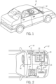
- FIG. 1 is a perspective view of an embodiment of a vehicle 10, which may utilize a regenerative braking system.
- vehicle 10 which may utilize a regenerative braking system.
- FIG. 1 is a perspective view of an embodiment of a vehicle 10, which may utilize a regenerative braking system.
- the battery system 12 may be placed in a location in the vehicle 10 that would have housed a traditional battery system.
- the vehicle 10 may include the battery system 12 positioned similarly to a lead-acid battery of a typical combustion-engine vehicle (e.g., under the hood of the vehicle 10).
- the battery system 12 may be positioned to facilitate managing temperature of the battery system 12. For example, in some embodiments, positioning a battery system 12 under the hood of the vehicle 10 may enable an air duct to channel airflow over the battery system 12 and cool the battery system 12.
- the battery system 12 includes an energy storage component 13 coupled to an ignition system 14, an alternator 15, a vehicle console 16, and optionally to an electric motor 17.
- the energy storage component 13 may capture/store electrical energy generated in the vehicle 10 and output electrical energy to power electrical devices in the vehicle 10.
- the battery system 12 may supply power to components of the vehicle's electrical system, which may include radiator cooling fans, climate control systems, electric power steering systems, active suspension systems, auto park systems, electric oil pumps, electric super/turbochargers, electric water pumps, heated windscreen/defrosters, window lift motors, vanity lights, tire pressure monitoring systems, sunroof motor controls, power seats, alarm systems, infotainment systems, navigation features, lane departure warning systems, electric parking brakes, external lights, or any combination thereof.
- the energy storage component 13 supplies power to the vehicle console 16 and the ignition system 14, which may be used to start (e.g., crank) the internal combustion engine 18.
- the energy storage component 13 may capture electrical energy generated by the alternator 15 and/or the electric motor 17.
- the alternator 15 may generate electrical energy while the internal combustion engine 18 is running. More specifically, the alternator 15 may convert the mechanical energy produced by the rotation of the internal combustion engine 18 into electrical energy. Additionally or alternatively, when the vehicle 10 includes an electric motor 17, the electric motor 17 may generate electrical energy by converting mechanical energy produced by the movement of the vehicle 10 (e.g., rotation of the wheels) into electrical energy.
- the energy storage component 13 may capture electrical energy generated by the alternator 15 and/or the electric motor 17 during regenerative braking.
- the alternator 15 and/or the electric motor 17 are generally referred to herein as a regenerative braking system.
- the energy storage component 13 may be electrically coupled to the vehicle's electric system via a bus 19.
- the bus 19 may enable the energy storage component 13 to receive electrical energy generated by the alternator 15 and/or the electric motor 17. Additionally, the bus 19 may enable the energy storage component 13 to output electrical energy to the ignition system 14 and/or the vehicle console 16. Accordingly, when a 12 volt battery system 12 is used, the bus 19 may carry electrical power typically between 8-18 volts.
- the energy storage component 13 may include multiple battery modules.
- the energy storage component 13 includes a lithium ion (e.g., a first) battery module 20 and a lead-acid (e.g., a second) battery module 22, which each includes one or more battery cells.
- the energy storage component 13 may include any number of battery modules.
- the lithium ion battery module 20 and lead-acid battery module 22 are depicted adjacent to one another, they may be positioned in different areas around the vehicle.
- the lead-acid battery module 22 may be positioned in or about the interior of the vehicle 10 while the lithium ion battery module 20 may be positioned under the hood of the vehicle 10.
- the energy storage component 13 may include multiple battery modules to utilize multiple different battery chemistries. For example, when the lithium ion battery module 20 is used, performance of the battery system 12 may be improved since the lithium ion battery chemistry generally has a higher coulombic efficiency and/or a higher power charge acceptance rate (e.g., higher maximum charge current or charge voltage) than the lead-acid battery chemistry. As such, the capture, storage, and/or distribution efficiency of the battery system 12 may be improved.
- the battery system 12 may additionally include a control module 24. More specifically, the control module 24 may control operations of components in the battery system 12, such as relays (e.g., switches) within energy storage component 13, the alternator 15, and/or the electric motor 17. For example, the control module 24 may regulate amount of electrical energy captured/supplied by each battery module 20 or 22 (e.g., to de-rate and re-rate the battery system 12), perform load balancing between the battery modules 20 and 22, determine a state of charge of each battery module 20 or 22, determine temperature of each battery module 20 or 22, control voltage output by the alternator 15 and/or the electric motor 17, and the like.
- the control module 24 may control operations of components in the battery system 12, such as relays (e.g., switches) within energy storage component 13, the alternator 15, and/or the electric motor 17.
- the control module 24 may regulate amount of electrical energy captured/supplied by each battery module 20 or 22 (e.g., to de-rate and re-rate the battery system 12), perform load balancing between the battery modules 20 and 22,
- control unit 24 may include one or more processor 26 and one or more memory 28. More specifically, the one or more processor 26 may include one or more application specific integrated circuits (ASICs), one or more field programmable gate arrays (FPGAs), one or more general purpose processors, or any combination thereof. Additionally, the one or more memory 28 may include volatile memory, such as random access memory (RAM), and/or non-volatile memory, such as read-only memory (ROM), optical drives, hard disc drives, or solid-state drives. In some embodiments, the control unit 24 may include portions of a vehicle control unit (VCU) and/or a separate battery control module.
- VCU vehicle control unit
- the battery module 20 includes a number of individual electrochemical cells 30 (e.g., Li-ion electrochemical cells) housed in a housing 31 of the battery module 20.
- the housing 31 includes a top side 32 (e.g., top wall), a bottom side 34 (e.g., bottom wall), and two reinforcing sides 35, 36 (e.g., reinforcing walls or reinforcing lateral sides).
- the housing 31 in the illustrated embodiment is open on a front side 38 (e.g., front lateral side) and closed on a back side 40 (e.g., back lateral side) of the housing 31.
- a front side 38 e.g., front lateral side
- a back side 40 e.g., back lateral side
- reference to the top side 32, the bottom side 34, the two reinforcing sides 35, 36, the front side 38, and the back side 40 in the illustrated embodiment may refer to an orientation of the battery module 20 (and, thus, the housing 31 thereof) within the vehicle 10.
- Other embodiments may include similar relative arrangements with respect to the components (e.g., the sides) of the housing 31, but may include a different positioning within the vehicle 10.
- the electrochemical cells 30 are disposed into the housing 31 such that terminal ends 42 of the electrochemical cells 30 (e.g., having terminals 43) are proximate to the open front side 38 of the housing 31, and base ends 44 opposite to the terminal ends 42 are proximate to the back side 40 of the housing 31. Further, the electrochemical cells 30 are stacked (e.g., in two stacks 46 or columns), with broad faces 45 of the electrochemical cells 30 (e.g., broad faces 45 extending between the base ends 44 and the terminal ends 42) stacked proximate to each other (e.g., aligned with one another).
- terminal ends 42 of the electrochemical cells 30 e.g., having terminals 43
- base ends 44 opposite to the terminal ends 42 are proximate to the back side 40 of the housing 31.
- the electrochemical cells 30 are stacked (e.g., in two stacks 46 or columns), with broad faces 45 of the electrochemical cells 30 (e.g., broad faces 45 extending between the base ends 44 and the terminal ends 42
- the housing 31 also includes a partition 47 configured to separate the two stacks 46 of electrochemical cells 30, where the partition 47 includes ribs or spacers 48 configured to separate (e.g., space) each electrochemical cell 30 from one another (e.g., each of the cells 30 in a single stack 46).
- the electrochemical cells 30 fit into slots defined by the ribs 48 of the partition 47, where the ribs 48 enable a space between adjacent electrochemical cells 30 in the stack 46.
- ribs 48 may also be disposed above the top electrochemical cell 30 in each stack 46 and below the bottom electrochemical cell 30 in each stack 46, which enables a space between the uppermost electrochemical cell 30 and the top side 32 of the housing 31 and the lowermost electrochemical cell 30 and the bottom side 34 of the housing 31.
- corresponding ribs 48 may be disposed on the inside of the two reinforcing sides 35, 36 to correspond (e.g., align) with the ribs 48 on the partition 47 for spacing the electrochemical cells 30 in each stack 46.
- the space between adjacent electrochemical cells 30 e.g., enabled by the ribs 48
- coolant e.g., air
- the open front side 38 of the housing 31 may be at least partially closed by an e-carrier 49 of the housing 31, which is configured to establish electrical connections between the electrochemical cells 30 (e.g., by electrically coupling the terminals 43 of the electrochemical cells 30) and may also be configured to serve as a cover for the open front side 38 of the housing 31.
- An additional cover 51 may fit over the e-carrier 49 to fully enclose (e.g., seal) the housing 31 by fully covering the open front side 38.
- a top cover 50 of the battery module 20 may fit over the top side 32 of the housing 31.
- Certain components (e.g., control circuitry) of the battery module 20 may be disposed on top of the top side 32, between the top side 32 of the housing 31 and the top cover 50 of the battery module 20 that fits over the top side 32.
- a hood 54 of the battery module 20 may be disposed over the top cover 50 of the housing 31.
- a fan 62 may be disposed under the hood 54, between the hood 54 and the top cover 50 of the housing 31 (e.g., the top cover 50 disposed onto the top side 32 of the housing 31).
- the hood 54 may be used as an airflow guide to guide an airflow from the fan 62 to a particular area or areas of the housing 31.
- a connecting conduit may be fluidly coupled between the fan 62 and a particular portion of the housing 31 intended to receive the airflow from the fan 62.
- the connecting conduit may act as an airflow guide to guide the airflow to particular areas of the housing 31.
- the fan 62 is configured to blow air into an inside 64 of the housing 31.
- the fan 62 includes an air intake 63 that draws air into the fan 62 through one or more openings 61 in the hood 54.
- the openings 61 are disposed on one or more side surfaces 65 of the hood 54. Disposing the opening(s) 61 on the side surface(s) 65 may reduce a likelihood that contaminants (e.g., dust or particles) fall into and under the hood 54 from above the hood 54 (e.g., due to gravity).
- the fan 62 draws air into the fan 62 via the air intake 63 and blows the air through an entry point into the inside 64 of the housing 31.
- the fan 62 blows air toward a cover opening 68 in the top cover 50.
- the cover opening 68 may be fluidly coupled to a top side opening 70 disposed in the top side 32 of the housing 31, where the top side opening 70 is fluidly coupled to the inside 64 of the housing 31. Accordingly, air is blown from the fan 62, through the cover opening 68, and through the top side opening 70 into the inside 64 of the housing 31 of the battery module 20.
- one or more sponge filters 71 are disposed in either the cover opening 68 or the top side opening 70, or both, and are configured to extract water or other liquids or particles from the airflow generated by the fan 62.
- the electrochemical cells 30 are spaced via spacers 48 on the partition 47 separating the stacks 46 of electrochemical cells 30 and the corresponding spacers 48 disposed on the reinforcing sides 35, 36 (e.g., on the insides of the reinforcing sides 35, 36). Accordingly, air blown into the inside 64 of the housing 31 via the fan 62 is routed between, over, and/or under the electrochemical cells 30. Depending on the embodiment, air may also pass over the base ends 44 and/or terminal ends 42 of the electrochemical cells 30. Any fluid or water in the air flow on the inside 64 of the housing 31 may gather in a recess 75 disposed on the inside 64 of the housing 31 recessed into, for example, the bottom side 34 of the housing 31. However, any number of recesses 75 may be included to gather the water or other liquids, and the one or more recesses 75 may be disposed on any appropriate portion of the inside 64 of the housing 31.
- the air travels from the back side 40 of the housing 31 toward the front side 38 of the housing 31 and outwardly toward the reinforcing (e.g., lateral) sides 35, 36 of the housing 31, and exits the inside 64 of the housing 31 through vents 76 (e.g., slotted vents) disposed on the outsides of the reinforcing sides 35, 36.
- the vents 76 may be substantially aligned with the spaces between the electrochemical cells 30, but may be disposed on any portion of the reinforcing sides 35, 36. Further, some of the vents 76 may be aligned with the space above the top electrochemical cell 30 in each stack 46, and/or with the space below the bottom electrochemical cell 30 in each stack 46.
- vents 76 provide access to lower outside pressures such that air in the housing 31 seeks the most direct path to the vents 76.
- flow guide features may be disposed in the inside 64 of the housing 31 to provide air distribution.
- the guide features may enable the air to flow from the back side 40 toward the front side 38 before being pushed through the vents 76, which may enable more efficient and more even cooling of all of the electrochemical cells 30.
- the flow guide features will be discussed in detail below with reference to later figures.
- the vents 76 may include features (e.g., filters) that protect against contaminants entering the vents 76.
- Disposing the fan 62 on the top cover 50 (e.g., above the top side 32) of the housing 31, as opposed to directly proximate to (or on) the back side 40 of the housing 31, may substantially reduce a footprint 90 of the battery module 20.
- the footprint 90 of the battery module 20 may define the largest cross-sectional area of the battery module 20 with respect to a plane defined by directions 74 and 92 in the illustrated embodiment.
- a vehicle utilizing the battery module 20 may have a pre-defined (or allotted) space (e.g., surface area) on which the battery module 20 is to be positioned. The allotted surface area within the vehicle may be oriented substantially parallel with the footprint 90 of the battery module 20 such that the battery module 20 covers the allotted surface area from overhead.
- the illustrated battery module 20 is disposed into the vehicle such that the illustrated footprint 90 aligns and corresponds with the allotted space in the vehicle.
- the fan 62 By disposing the fan 62 on the top cover 50 of the housing 31, and diverting the airflow to the inside 64 of the housing 31, the airflow extracts heat from the electrochemical cells 30 and does not contribute to the footprint 90.
- Disposing the fan 62 on other areas of the battery module 20 e.g., on the back side 40 of the housing 31) would substantially increase the footprint 90 of the battery module 20.
- the fan 62 in the illustrated embodiment is disposed on the top cover 50 over the top side 32 of the housing 31 and blows air through the cover opening 68 and the top side opening 70 into the inside 64 of the housing 31.
- the fan 62 may blow air toward the back side 40 of the housing 31 and a flow diverting feature may divert the flow from the top side 32 (e.g., from the top cover 50 over the top side 32) of the housing 31, over a portion of the back side 40 of the housing 31, and into the inside 64 of the housing 31.
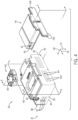
- a partially exploded back perspective view of an embodiment of the battery module 20 is shown in FIG. 4 .
- the hood 54 is configured to extend over the fan 62 and contact the top cover 50 on the top side 32 of the housing 31 to substantially surround the fan 62.
- the hood 54 also includes an extension 100 configured to extend along the back side 40 of the housing 31 in direction 72.
- the extension 100 is configured to guide the airflow from the fan 62 downwardly in direction 72, along the back side 40 of the housing 31.
- the extension 100 also includes outer ridges 102 configured to contact (e.g., seal against) the back side 40 of the housing 31, such that air blown by the fan 62 and diverted along the back side 40 of the housing 31 is contained within the outer ridges 102.
- one or more slots 104 are disposed in the back side 40 of the housing 31 to enable the air to flow into the inside 64 of the housing 31 through the slots 104.
- a cooling plate may be disposed in the back side 40 of the housing 31 in some embodiments, where the cooling plate includes a material (e.g., metal) with a higher thermal conductivity than the material of the back side 40 of the housing 31.
- the cooling plate may be configured to extract heat from the electrochemical cells 30.
- the cooling plate may be disposed on other sides of the housing 31, such as the reinforcing sides 35, 36 or the top side 32. The cooling plate may or may not cooperate with the airflow generated by the fan 62 to provide thermal management to the battery module 20
- the slots 104 are substantially aligned with the spaces between the electrochemical cells 30 disposed in the inside 64 of the housing 31, which may enable the air to pass directly to the spaces without being substantially interrupted by the base ends 44 of the electrochemical cells 30 disposed proximate to the back side 40 of the housing 31 (see FIG. 3 ).
- the slots 104 may be disposed on any portion of the back side 40 that enables the slots 104 to pass the airflow from the back side 40 of the housing 31 into the inside 46 of the housing 31. Further, any number of slots 104 may be included in the back side 40 of the housing 31.
- 1, 2, 3, 4, 5, 6, 7, 8 or more slots 104 may be disposed in the back side 40 of the housing 31 to fluidly couple to the inside 64 of the housing 31. Further still, the slots 104 may actually be smaller slots 104 disposed substantially in a middle portion of the back side 40 of the housing 31. For example, the slots 104 may be small openings in a middle portion of the back side 40 of the housing 31 disposed proximate to the partition 47 on the inside 64 of the housing 31.
- the air is directed into the inside 64 of the housing 31 through the slots 104 on the back side 40 of the housing 31 (e.g., through a portion of an airflow path), the air is directed between the electrochemical cells 30 (e.g., through another portion of the airflow path) disposed on the inside 64 of the housing 31.
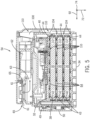
- FIG. 5 a cross-sectional side view of an embodiment of the battery module 20 having an airflow path 110 from the fan 62, along the back side 40 of the housing 31, and through the inside 64 of the housing 31 is shown in FIG. 5 , taken along line 5-5 in FIG. 4 .
- the portion of the airflow path 110 along the back side 40 of the housing 31 is fluidly coupled to the portion of the airflow path 110 on the inside 64 of the housing 31.
- the air flows through the airflow path 1 10 from the fan 62, along the back side 40 of the housing 31, through the slots 104 on the back side 40 of the housing 31, and into the inside 64 of the housing 31.
- an entry point of the air into the inside 64 of the housing 31 may be through the top side 32 (e.g., through the top cover 50 and through the top side 32) of the housing 31 or at some other location, as opposed to through the illustrated slots 104.
- the back side 40 includes four slots 104 substantially aligned with portions of the airflow path 110 above and below each of the electrochemical cells 30 disposed on the inside 64 of the housing 31.
- the air is routed through the slots 104 and between the electrochemical cells 30, and exits through openings 76 (e.g., vents) in the reinforcing (e.g., lateral) sides 35, 36 of the housing 31.
- the airflow also passes over the base ends 44 of the electrochemical cells 30 within a space 112 (e.g., of the airflow path 110) between the base ends 44 of the electrochemical cells 30 and the back side 40 of the housing 31 having the slots 104.
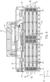
- FIG. 6 a front cross-sectional view of an embodiment of the battery module 20 having the airflow path 110 is shown in FIG. 6 , taken along line 6-6 in FIG. 4 .
- the air is routed between the electrochemical cells 30 (e.g., in direction 92) and outwardly (e.g., parallel to direction 74) toward the reinforcing sides 35, 36.
- the reinforcing sides 35, 36 include the vents 76, as described with reference to FIG. 3 , to vent the air from the airflow path 110 on the inside 64 of the housing 31 to the surrounding environment 80.
- vents 76 generally are disposed on a portion of the reinforcing sides 35, 36 proximate to the front side 38 of the housing 31 (as shown in FIG. 3 ). This may enable the air to flow over the electrochemical cells 30 from the back side 40 of the housing 31 toward the front side 38 of the housing 31 before being sucked through the vents 76 by the lower pressure in the surrounding environment 80, which may enable more even (e.g., homogenous) cooling of all of the electrochemical cells 30.
- flow guide extension features may also help guide the air toward the front side 38 of the housing 31 before the air is vented through the vents 76.
- internal surfaces on the inside 64 of the housing 31 may include the flow guide extension features configured to guide the air toward portions of the electrochemical cells 30 that may otherwise, in the absence of the flow guide extension features, not be cooled by the cooling air.
- the air may only contact small portions of certain of the electrochemical cells 30.
- FIG. 7 An embodiment of the housing 31 having flow guide extension features 120 configured to guide the airflow over the electrochemical cells 30 is shown in FIG. 7 .
- the housing 31 includes the extension features 120 on a top internal surface 122 on the top side 32 of the housing 31.
- the illustrated extension features 120 are configured to contact the uppermost electrochemical cell 30 (e.g., the broad face 45 of the uppermost electrochemical cell 30), thereby defining multiple airflow channels between the uppermost electrochemical cell 30, the top internal surface 122 on the top side 32 of the housing 31, and adjacent extension features 120.
- the multiple airflow channels guide air entering into the inside 64 of the housing 31 (e.g., through the slot 104) toward the front side 38 of the housing 31.
- a cover would normally be disposed over the front side 38 of the housing 31, and the air would be directed along the front side 38 of the housing 31 toward the vent 76, which sucks the air toward the vent 76 (e.g., due to a pressure difference between the inside 64 of the housing 31 and the surrounding environment 80) and vents the air to the surrounding environment 80.
- the extension features 120 are configured to route the air from the back side 40 of the housing 31 (e.g., after passing through the slot 104) toward the front side 38 of the housing 31, where the air is then sucked through the vent 76 disposed on the reinforcing sides 35, 36 of the housing 31 to the surrounding environment 80.
- the air may be sucked directly from the slot 104 to the vent 76, which would enable the air to exit the inside 64 of the housing 31 without contacting substantial portions of the electrochemical cells 30 disposed in the housing 31.
- portions of the electrochemical cells 30 proximate to the partition 47 and the front side 38 of the housing 31 may not be cooled by the air if not for the flow guide extension features 120 described above.
- each of the extension features 120 may extend a substantially equal distance from the back side 40 of the housing 31 toward the front side 38 of the housing 31, or the extension features 120 may extend different distances.
- each successive extension feature 120 e.g., from the partition 47 outwardly
- may extend a lesser distance e.g., as measured from the back side 40 of the housing 31 toward the front side 38 of the housing 31 than the previous extension feature 120.
- extension features 120 all extending the same distance may enable adverse pressure drops in the inside 64 of the housing 31, causing back flow from the front side 38 of the housing 31 to the back side 40 of the housing 31.
- pressure differences between the slot 104 and the vent 76 may be managed to enable the air to flow over all portions of all of the electrochemical cells 30 substantially equally while blocking the back flow described above.
- extension features 120 are also disposed on other portions of the housing 31.
- FIG. 8 an embodiment of the housing 31 having extension features 120 disposed on a bottom internal surface 130 on the inside 64 of the bottom side 34 of the housing 31 and configured to guide the airflow under the lowermost electrochemical cell 30 (e.g., from the back side 40 to the front side 38 of the housing 31) is shown in FIG. 8 .
- the extension features 120 on the bottom internal surface 130 of the bottom side 34 of the housing 31 operate in the same or a similar manner as those disposed on the top internal surface 122 in FIG. 7 and described with reference to FIG. 7 , except that the extension features 120 on the bottom internal surface 130 engage the broad face 45 of the lowermost electrochemical cell 30 underneath the electrochemical cell 30.
- FIG. 9 a schematic perspective view of an embodiment of an air volume (e.g., of the airflow) over the electrochemical cells 30 is shown in FIG. 9 .
- the air enters an entry point 132 into the housing 31.
- the entry point 132 may be through the top side 32 of the housing 31, as shown in FIG. 3 , or through slots 104 on the back side 40 of the housing 31, as shown in FIG. 4 .
- the flow guide extension features 120 then guide the air flow from the back side 40 of the housing 31 (e.g., proximate to the base ends 44 of the electrochemical cells 30) toward the front side 38 of the housing 31 (e.g., proximate to the terminal ends 42 of the electrochemical cells 30).
- the flow guide extension features 120 may successively (e.g., starting proximate to the partition 47 and working toward the reinforcing side 35) extend a lesser distance from the back side 40 toward the front side 38 of the housing 31.
- the entry point 132 and the vents 76 are disposed caddy-corner to one another (e.g., on diagonally opposing sides of the electrochemical cells 30. Accordingly, in the absence of the extension features 120, the airflow would naturally tend to flow from the entry point 132 diagonally across the electrochemical cells 30 to the vents 76.
- the flow guide extension features 120 are included to direct the airflow upwardly across the electrochemical cells 30.
- flow guide extension features 120 that all extend the same distance (e.g., from the back side 40 of the housing 31 up to the front side 38 of the housing 31) may enable an adverse pressure drop that causes back flow from the front side 38 of the housing 31 to the back side 40 of the housing 31.
- the airflow travels along the extension features 120 and beyond tips of the extension features 120, and then angles directly toward the vents 76.
- the illustrated lengths of the extension features 120 enable the airflow to pass over all portions of the electrochemical cells 30.
- the pressure differences between the entry point (e.g., proximate to the base ends 44 of the electrochemical cells 30) and the vents 76 (in the reinforcing side 35) are managed, via the extension features 120, to enable the air to flow over all portions of all of the electrochemical cells 30 substantially equally and then vent through the vents 76 disposed in the reinforcing side 35.
- a diagonal flow guide extension feature 134 is disposed upstream of the electrochemical cells 30.
- the diagonal flow guide extension 134 may be disposed in an airspace above the electrochemical cells 30.
- an airspace may be located between the entry point 132 into the housing 31 and the electrochemical cells 30.
- the diagonal flow guide extension 134 may be disposed in said airspace, and may be configured to direct some of the air above 135 the diagonal flow guide extension 134 and some of the air below 136 the flow guide extension 134.
- the positioning of the diagonal flow guide extension 134 may vary within the airspace depending on expected pressure differences over various portions of the electrochemical cells 30.
- electrochemical cells 30 may include guiding features configured to guide the airflow from the slots 104 (or some other entry point into the inside 64 of the housing 31) at the back side 40 of the housing 31 toward the front side 38 of the housing 31.
- FIG. 10 A perspective view of an embodiment of one electrochemical cell 30 having flow guide cell extension features 140 is shown in FIG. 10 .
- the flow guide cell extensions 140 are disposed on the broad faces 45 (e.g., bodies) of the electrochemical cell 30 and are configured to guide airflow from an area proximate to the base end 44 of the electrochemical cell 30 to an area proximate to the terminal end 42 (e.g., having terminals 43) of the electrochemical cell 30.
- the electrochemical cell 30 may be otherwise disposed in the housing 31 such that the flow guide cell extensions 140 guide the air from the terminal end 42 toward the base end 44.
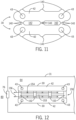
- the flow guide cell extensions 140 may contact an adjacent electrochemical cell 30 to define multiple fluid channels between the electrochemical cells 30 (e.g., where the multiple fluid channels are in fluid communication with the entry point into the housing 31 and to the vent(s) 76), or the flow guide cell extensions 140 may engage with the flow guide cell extensions 140 of the adjacent electrochemical cell 30 to define the multiple fluid channels. Further, if the electrochemical cell 30 is the top or bottom electrochemical cell 30 in the stack 46, the flow guide cell extensions 140 may interface with a surface of the housing 31 to enable guiding of the air along the electrochemical cell 30 in accordance with the above description. An embodiment of two adjacent electrochemical cells 30 having engaged flow guide cell extensions 140 is shown in a schematic front view in FIG. 11 . Fluid channels 142 are defined between the engaged guide features 140.
- inserts may include flow guide features and may be disposed between adjacent electrochemical cells 30 on the inside 64 of the housing 31, where the flow guide features of the inserts are configured to guide the flow of air between the electrochemical cells 30 from the back side 40 of the housing 31 (e.g, from the base end 44 of the electrochemical cell 30) toward the front side 38 of the housing 31 (e.g., toward the terminal end 42 of the electrochemical cell 30).
- a schematic front view of an embodiment of a flow guide insert 150 between two adjacent electrochemical cells 30 on the inside 64 of the housing 31 is shown in FIG. 12 .
- the flow guide insert 150 includes guide features 152 coupled to a thin connecting member 153 (e.g., thin connecting piece) of the flow guide insert 150 and configured to engage with the adjacent electrochemical cells 30.
- the thin connecting member 153 is disposed proximate to the base ends 44 of the electrochemical cells 30 (e.g., opposite to the illustrated terminal ends 42), and enables the air flow to pass over the thin connecting member 153 into multiple fluid channels defined in part by each pair of adjacent guide features 152.
- each pair of adjacent guide features 152 contacts the adjacent electrochemical cells 30 to define a fluid channel through which the air flows toward the terminal ends 42 of the electrochemical cells 30 (e.g., indicated by x-arrows 154 toward the viewer).
- the channels fluidly couple the entry point into the inside 64 of the housing 31 and the vent(s) 76, but enable the airflow to pass over the electrochemical cells 30 before being vented.
- the guide features 152 block the air from simply being pushed out of the inside 64 of the housing 31 by the vent 76 before passing over the electrochemical cells 30, as previously described with reference to other disclosed guide features. Once the air has passed over the electrochemical cells 30 (e.g., beyond the terminal ends 42 of the electrochemical cells 30), the air may be sucked toward the vent 76, as shown by arrows 156.
- the flow guide inserts 150 may be utilized to space the electrochemical cells 30 instead of, or in addition to, the ribs 48 described with reference to FIG. 3 .
- flow guide insert 150 may be configured similar to or other than what is shown in FIG. 12 .
- schematic perspective views of various embodiments of the flow guide insert 150 are shown in FIGS. 13 and 14 .
- the disclosed battery modules include active thermal management features generally configured to enable fluid flow on an inside of a housing of the battery module.
- the active thermal management features themselves (e.g., a fan) may be disposed on an outer surface of the housing, which may reduce a footprint of the battery module, and may be configured to provide air flow that is directed (e.g., via flow diverting features) into the housing through an entry point on the housing (e.g., on a top or side surface of the housing).
- the flow may be directed by flow guide features (e.g., inserts between electrochemical cells and/or extensions of surfaces of the housing or electrochemical cells) configured to guide the flow proximate to various portions of the electrochemical cells, thereby providing a more even (e.g., substantially homogenous) heat extraction from all of the electrochemical cells and from all areas of the electrochemical cells.
- flow guide features e.g., inserts between electrochemical cells and/or extensions of surfaces of the housing or electrochemical cells
Landscapes
- Engineering & Computer Science (AREA)
- Chemical & Material Sciences (AREA)
- Chemical Kinetics & Catalysis (AREA)
- Electrochemistry (AREA)
- General Chemical & Material Sciences (AREA)
- Manufacturing & Machinery (AREA)
- Life Sciences & Earth Sciences (AREA)
- Sustainable Development (AREA)
- Sustainable Energy (AREA)
- Power Engineering (AREA)
- Transportation (AREA)
- Mechanical Engineering (AREA)
- Materials Engineering (AREA)
- Secondary Cells (AREA)
- Battery Mounting, Suspending (AREA)
Claims (12)
- Module de batterie (20), comprenant :- un carter (31), comprenant une paroi supérieure, une paroi inférieure, une paroi arrière s'étendant entre la paroi supérieure et la paroi inférieure, et un intérieur (64) situé entre la paroi supérieure et la paroi inférieure ;- des cellules électrochimiques (30) disposées en un ou plusieurs empilements (46) dans l'intérieur (64) du carter (31), les cellules électrochimiques (30) étant espacées les unes des autres de façon à permettre un écoulement d'air entre les cellules électrochimiques (30), l'empilement ou les empilements (46) des cellules électrochimiques (30) s'étendant vers le haut de la paroi inférieure du carter (31) à la paroi supérieure du carter (31), des extrémités de base (44) des cellules électrochimiques (30) étant disposées à proximité de la paroi arrière du carter (31) et des extrémités terminales (42) des cellules électrochimiques (30) étant disposées à proximité de la paroi avant du carter (31), des grandes faces (45) des cellules électrochimiques (30) s'étendant entre les extrémités de base (44) et les extrémités terminales (42) des cellules électrochimiques (30) et étant empilées à proximité les unes des autres ;- un ventilateur (62) disposé sur une partie extérieure de la paroi supérieure du carter (31) ;- un capot (54) disposé sur le ventilateur (62) et conçu pour entrer en contact avec le carter (31) afin de diriger l'écoulement d'air depuis le ventilateur (62) dans l'intérieur (64) du carter (31) à travers un point d'entrée (132) disposé sur la paroi arrière du carter (31), le point d'entrée (132) comprenant des ouvertures en forme de fentes (104) formées à travers la paroi arrière du carter (31) ;- un orifice d'évacuation (76) mettant l'intérieur (64) du carter (31) en communication fluidique avec l'extérieur du carter (31) et conçu pour évacuer l'écoulement d'air de l'intérieur (64) du carter (31) vers l'extérieur du carter (31) ; et- des éléments de guidage d'écoulement conçus pour guider l'écoulement d'air depuis le point d'entrée (132) le long des cellules électrochimiques (30),dans lequel le capot (54) comprend une saillie (100) conçue pour s'étendre depuis la paroi supérieure du carter (31) sur la paroi arrière du carter (31), la saillie (100) comprenant des rebords extérieurs (102) conçus pour s'appliquer de manière étanche contre la paroi arrière du carter autour des ouvertures en forme de fentes (104), et dans lequel la saillie (100) est conçue pour guider l'écoulement d'air depuis le ventilateur (62) sur la partie extérieure de la paroi supérieure du carter (31) à la paroi arrière du carter (31) et dans les ouvertures en forme de fentes (104) formées à travers la paroi arrière du carter (31).
- Module de batterie (20) selon la revendication 1,
dans lequel les éléments de guidage d'écoulement sont des saillies de guidage d'écoulement qui s'étendent à partir d'une surface intérieure supérieure (122) de la paroi supérieure du carter (31), à partir d'une surface intérieure inférieure (130) de la paroi inférieure du carter (31), ou à la fois à partir de la surface intérieure supérieure (122) et de la surface intérieure inférieure (130). - Module de batterie (20) selon la revendication 1 ou 2,
dans lequel les éléments de guidage d'écoulement sont des saillies de cellules de guidage d'écoulement (140) qui s'étendent à partir des corps des cellules électrochimiques (30). - Module de batterie (20) selon la revendication 3,
dans lequel les saillies de cellules de guidage d'écoulement (140) de cellules électrochimiques (30) adjacentes sont conçues pour entrer en contact les unes avec les autres de façon à former de multiples canaux à fluide (142) entre les cellules électrochimiques (30) adjacentes, et les multiples canaux à fluide (142) sont en accouplement fluidique avec le point d'entrée (132) et avec l'orifice d'évacuation (76). - Module de batterie (20) selon l'une des revendications 1 à 4,
dans lequel les éléments de guidage d'écoulement sont accouplés à des garnitures de guidage d'écoulement (150) disposées entre des cellules électrochimiques (30) adjacentes et les éléments de guidage d'écoulement entrent en contact avec les cellules électrochimiques (30) adjacentes de façon à former des canaux à fluide entre les cellules électrochimiques (30) adjacentes, et les canaux à fluide sont en accouplement fluidique avec le point d'entrée (132) et l'orifice d'évacuation (76). - Module de batterie (20) selon la revendication 5,
dans lequel chaque garniture de guidage d'écoulement (150) comprend un élément de raccordement fin (153) et les éléments de guidage d'écoulement (152) sont accouplés à l'élément de raccordement fin (153), de telle sorte que l'écoulement d'air peut passer sur l'élément de raccordement fin et entre les éléments de guidage d'écoulement (152) adjacents en contact avec les cellules électrochimiques (30) adjacentes. - Module de batterie (20) selon l'une des revendications 1 à 6, comprenant un filtre spongieux (71) disposé dans l'écoulement d'air en amont des cellules électrochimiques (30), dans lequel le filtre spongieux (71) est conçu pour extraire des particules de l'écoulement d'air.
- Module de batterie (20) selon l'une des revendications 1 à 7, comprenant un renfoncement (75) formé sur une surface intérieure de la paroi inférieure du carter (31) et le renfoncement (75) est conçu pour recueillir des particules provenant de l'écoulement d'air.
- Module de batterie (20) selon l'une des revendications 1 à 8,
dans lequel les éléments de guidage d'écoulement sont conçus pour guider l'écoulement d'air depuis le point d'entrée (132) à proximité de la paroi arrière du carter (31) en direction de la paroi avant du carter (31). - Module de batterie (20) selon la revendication 9,
dans lequel l'orifice d'évacuation (76) est formé dans une paroi latérale de renforcement du carter (31) plus près de la paroi avant du carter (31) que de la paroi arrière du carter (31). - Module de batterie (20) selon la revendication 10,
dans lequel les éléments de guidage d'écoulement s'étendent le long des grandes faces (45) depuis un emplacement à proximité des extrémités de base (44) des cellules électrochimiques (30) en direction des extrémités terminales (42) des cellules électrochimiques (30), et dans lequel chaque élément de guidage d'écoulement suivant, depuis un emplacement à proximité de l'orifice d'évacuation (76) vers l'extérieur, s'étend sur une plus grande distance depuis un emplacement à proximité des extrémités de base (44) des cellules électrochimiques (30) en direction des extrémités terminales (42) des cellules électrochimiques (30). - Module de batterie (20) selon l'une des revendications 1 à 11,
dans lequel le carter (31) ne comprend pas de plaque de refroidissement disposée sur le carter (31) à proximité de l'écoulement d'air généré par le ventilateur (62).
Applications Claiming Priority (2)
| Application Number | Priority Date | Filing Date | Title |
|---|---|---|---|
| US14/502,876 US10720683B2 (en) | 2014-09-30 | 2014-09-30 | Battery module thermal management features for internal flow |
| PCT/US2015/037088 WO2016053423A1 (fr) | 2014-09-30 | 2015-06-23 | Caractéristiques de gestion thermique de module de batterie pour circulation interne |
Publications (2)
| Publication Number | Publication Date |
|---|---|
| EP3201972A1 EP3201972A1 (fr) | 2017-08-09 |
| EP3201972B1 true EP3201972B1 (fr) | 2023-08-02 |
Family
ID=53783298
Family Applications (1)
| Application Number | Title | Priority Date | Filing Date |
|---|---|---|---|
| EP15747260.6A Active EP3201972B1 (fr) | 2014-09-30 | 2015-06-23 | Caractéristiques de gestion thermique de module de batterie pour circulation interne |
Country Status (4)
| Country | Link |
|---|---|
| US (1) | US10720683B2 (fr) |
| EP (1) | EP3201972B1 (fr) |
| CN (1) | CN107112455B (fr) |
| WO (1) | WO2016053423A1 (fr) |
Families Citing this family (22)
| Publication number | Priority date | Publication date | Assignee | Title |
|---|---|---|---|---|
| US11088409B2 (en) | 2016-06-06 | 2021-08-10 | Ads-tec Energy GmbH | Energy store in an installation housing and in a cooling air flow |
| JP6711234B2 (ja) | 2016-10-14 | 2020-06-17 | 株式会社デンソー | 電池ユニット |
| CN106450578B (zh) * | 2016-12-08 | 2023-08-22 | 湖南小步科技有限公司 | 一种电池包风冷系统 |
| JP6620337B2 (ja) * | 2016-12-20 | 2019-12-18 | 株式会社安川電機 | 電池ケースおよびロボット |
| WO2018143465A1 (fr) * | 2017-02-06 | 2018-08-09 | 日立オートモティブシステムズ株式会社 | Bloc-batterie et support |
| DE102017217118A1 (de) * | 2017-09-26 | 2019-03-28 | Robert Bosch Gmbh | Batteriemodul |
| US12500291B2 (en) * | 2018-11-30 | 2025-12-16 | Yui Lung Tong | Power supply apparatus and components thereof (venting) |
| USD998560S1 (en) * | 2019-02-08 | 2023-09-12 | Cps Technology Holdings Llc | Battery housing |
| JP6877485B2 (ja) * | 2019-05-21 | 2021-05-26 | 本田技研工業株式会社 | バッテリパック |
| CN210110904U (zh) * | 2019-09-19 | 2020-02-21 | 宁德时代新能源科技股份有限公司 | 下箱体、电池包及车辆 |
| KR102714488B1 (ko) * | 2019-12-12 | 2024-10-07 | 현대자동차주식회사 | 수냉식 배터리 배치구조가 개선된 하이브리드 차량 |
| JP7011677B2 (ja) * | 2020-03-02 | 2022-01-26 | 本田技研工業株式会社 | バッテリユニット |
| DE102020208669B3 (de) * | 2020-07-10 | 2021-08-19 | Vitesco Technologies Germany Gmbh | Batterie für ein Kraftfahrzeug und Kraftfahrzeug mit der Batterie |
| WO2022096115A1 (fr) * | 2020-11-05 | 2022-05-12 | Bluvein Innovation Ab | Système d'alimentation électrique d'au moins un véhicule à énergie électrique |
| JP7352588B2 (ja) * | 2021-03-15 | 2023-09-28 | 本田技研工業株式会社 | 燃料電池システム |
| CN113113706B (zh) * | 2021-03-19 | 2022-06-28 | 哈尔滨工业大学 | 一种应对锂电池停车热失控的自适应热管理系统 |
| EP4195368A1 (fr) * | 2021-12-09 | 2023-06-14 | MANN+HUMMEL GmbH | Module de distribution d'air et boîtier de batterie pour bloc-batterie |
| DE102022205292A1 (de) | 2022-05-25 | 2023-08-03 | Vitesco Technologies GmbH | Batterie für ein Kraftfahrzeug und Kraftfahrzeug mit einer Batterie |
| US12456855B2 (en) * | 2022-05-26 | 2025-10-28 | GM Global Technology Operations LLC | Thermally conducting bracket for busbar to cold plate heat transfer |
| RO137986A0 (ro) * | 2023-04-27 | 2024-02-28 | Raul Ioan Rişco | Modul baterie şi rack de stocare de energie |
| US20240413476A1 (en) * | 2023-06-08 | 2024-12-12 | GM Global Technology Operations LLC | Assembled manifold for thermal runaway vent gas transport in battery systems |
| CN119994354B (zh) * | 2025-04-17 | 2025-08-08 | 宁德时代新能源科技股份有限公司 | 电池装置以及用电装置 |
Family Cites Families (118)
| Publication number | Priority date | Publication date | Assignee | Title |
|---|---|---|---|---|
| US5215834A (en) | 1992-02-18 | 1993-06-01 | Globe Union Inc. | Battery thermal control system and method |
| US5385793A (en) | 1992-07-20 | 1995-01-31 | Globe-Union Inc. | Thermal management of battery systems |
| US5721064A (en) | 1993-04-30 | 1998-02-24 | Aer Energy Resources Inc. | Air manager system for reducing gas concentrations in a metal-air battery |
| US5449571A (en) | 1993-11-29 | 1995-09-12 | Store Heat And Produce Energy, Inc. | Encapsulations for thermal management system for battery |
| US5585204A (en) | 1993-12-27 | 1996-12-17 | Honda Giken Kogyo Kabushiki Kaisha | Temperature control structure for batteries and battery box for housing such batteries |
| US6455186B1 (en) | 1998-03-05 | 2002-09-24 | Black & Decker Inc. | Battery cooling system |
| US6343984B1 (en) | 1998-11-30 | 2002-02-05 | Network Appliance, Inc. | Laminar flow duct cooling system |
| JP3742261B2 (ja) | 1999-11-10 | 2006-02-01 | 株式会社マキタ | 電動工具用バッテリーパック |
| EP1249051B1 (fr) | 2000-01-19 | 2004-04-07 | Manhattan Scientifics, Inc. | Empilement de piles a combustible a ailettes de refroidissement et utilisation de graphite expanse dans des piles a combustible |
| US6628521B2 (en) | 2000-11-06 | 2003-09-30 | Adc Telecommunications, Inc. | Mechanical housing |
| US6459580B1 (en) | 2001-02-07 | 2002-10-01 | Compaq Information Technologies Group, Lp | Cooling system for removing heat from an object |
| JP4320133B2 (ja) | 2001-06-05 | 2009-08-26 | パナソニック株式会社 | 電池電源装置 |
| US9113577B2 (en) | 2001-11-27 | 2015-08-18 | Thermotek, Inc. | Method and system for automotive battery cooling |
| JP4053289B2 (ja) | 2001-12-12 | 2008-02-27 | 本田技研工業株式会社 | 蓄電池の温度制御装置、及びそれを用いた車両装置 |
| US7371965B2 (en) | 2002-05-09 | 2008-05-13 | Finisar Corporation | Modular cage with heat sink for use with pluggable module |
| JP4242665B2 (ja) * | 2002-05-13 | 2009-03-25 | パナソニック株式会社 | 組電池の冷却装置及び二次電池 |
| US6781830B2 (en) | 2002-11-05 | 2004-08-24 | Adc Dsl Systems, Inc. | Methods and systems of heat transfer for electronic enclosures |
| US7172831B2 (en) | 2003-01-09 | 2007-02-06 | Ford Motor Company | Battery system for automotive vehicle |
| US6866544B1 (en) | 2003-03-25 | 2005-03-15 | Cisco Technology, Inc. | Methods and apparatus for mounting an electromagnetic interference shielding cage to a circuit board |
| US6798663B1 (en) | 2003-04-21 | 2004-09-28 | Hewlett Packard Development Company, L.P. | Heat sink hold-down with fan-module attach location |
| US7189473B2 (en) | 2003-06-03 | 2007-03-13 | Eastway Fair Company Limited | Battery venting system |
| TWM248035U (en) | 2003-07-11 | 2004-10-21 | Asia Pacific Fuel Cell Tech | Cooling device of air-cooling type fuel battery set |
| US8945746B2 (en) | 2009-08-12 | 2015-02-03 | Samsung Sdi Co., Ltd. | Battery pack with improved heat dissipation efficiency |
| US7507500B2 (en) | 2004-05-17 | 2009-03-24 | Railpower Technologies Corp. | Design of a large battery pack for a hybrid locomotive |
| US7405932B2 (en) | 2004-07-19 | 2008-07-29 | Hewlett-Packard Development Company, L.P. | System and method for cooling electronic devices |
| US7357135B2 (en) | 2004-09-08 | 2008-04-15 | Steel Grip, Inc. | Protective hood with fan assembly |
| KR100649561B1 (ko) | 2004-09-21 | 2006-11-24 | 삼성에스디아이 주식회사 | 케이스와 이차전지 및 전지 모듈 |
| KR100853621B1 (ko) | 2004-10-26 | 2008-08-25 | 주식회사 엘지화학 | 전지팩의 냉각 시스템 |
| US20060093901A1 (en) | 2004-10-28 | 2006-05-04 | Gun-Goo Lee | Secondary battery module and cooling apparatus for secondary battery module |
| KR100669414B1 (ko) | 2004-11-30 | 2007-01-15 | 삼성에스디아이 주식회사 | 전지 모듈과 전지 모듈의 격벽 |
| US7388745B2 (en) | 2004-12-02 | 2008-06-17 | Hewlett-Packard Development Company, L.P. | Portable computer power system |
| TWI268995B (en) | 2004-12-24 | 2006-12-21 | Foxconn Tech Co Ltd | Fan duct device |
| JP4768277B2 (ja) | 2005-01-28 | 2011-09-07 | プライムアースEvエナジー株式会社 | 冷却装置及び電源装置 |
| EP1878085B1 (fr) | 2005-03-14 | 2016-04-20 | Johnson Controls Technology Company | Systeme de batteries au lithium |
| WO2006099602A2 (fr) | 2005-03-16 | 2006-09-21 | Ford Global Technologies, Llc | Systeme d'alimentation electrique |
| KR20060102852A (ko) | 2005-03-25 | 2006-09-28 | 삼성에스디아이 주식회사 | 이차 전지 모듈 |
| KR100648698B1 (ko) | 2005-03-25 | 2006-11-23 | 삼성에스디아이 주식회사 | 이차 전지 모듈 |
| JP4385020B2 (ja) | 2005-06-02 | 2009-12-16 | 本田技研工業株式会社 | 車両用電源装置 |
| DE102005031504A1 (de) | 2005-07-06 | 2007-01-11 | Daimlerchrysler Ag | Prismatische Batterie aus mehreren Einzelzellen |
| US8816645B2 (en) * | 2005-07-20 | 2014-08-26 | Aerovironment, Inc. | Integrated battery unit with cooling and protection expedients for electric vehicles |
| KR100684768B1 (ko) | 2005-07-29 | 2007-02-20 | 삼성에스디아이 주식회사 | 이차 전지 모듈 |
| KR100648704B1 (ko) | 2005-07-29 | 2006-11-23 | 삼성에스디아이 주식회사 | 이차 전지 모듈 |
| JP4659699B2 (ja) | 2005-07-29 | 2011-03-30 | 三星エスディアイ株式会社 | 電池モジュール |
| KR100932214B1 (ko) | 2005-10-14 | 2009-12-16 | 주식회사 엘지화학 | 열전소자를 이용한 전지팩의 열교환 시스템 |
| KR100937903B1 (ko) | 2005-11-03 | 2010-01-21 | 주식회사 엘지화학 | 전지팩의 밀폐형 열교환 시스템 |
| US7414841B2 (en) | 2006-01-19 | 2008-08-19 | Fu Zhun Precision Industry (Shen Zhen) Co., Ltd. | Electronic cooling system having a ventilating duct |
| JP5052057B2 (ja) | 2006-06-30 | 2012-10-17 | 三洋電機株式会社 | 電源装置 |
| US7558061B2 (en) | 2006-08-04 | 2009-07-07 | Hewlett-Packard Development Company, L.P. | Cooling fan module |
| EP2057702A1 (fr) | 2006-08-29 | 2009-05-13 | Johnson Controls Saft Advanced Power Solutions LLC | Module de batterie |
| CN100499983C (zh) | 2006-09-08 | 2009-06-10 | 富准精密工业(深圳)有限公司 | 散热装置 |
| FR2908557B1 (fr) | 2006-11-14 | 2009-02-06 | Vehicules Electr Societe Par A | Batterie electrique comprenant un systeme de conditionnement mecanique et thermique |
| US20080299448A1 (en) | 2006-11-20 | 2008-12-04 | Derrick Scott Buck | Battery unit with temperature control device |
| CN101627490B (zh) | 2006-12-14 | 2012-10-03 | 江森自控帅福得先进能源动力系统有限责任公司 | 电池模块 |
| JP4390802B2 (ja) | 2006-12-15 | 2009-12-24 | トヨタ自動車株式会社 | 車載バッテリ冷却構造 |
| WO2008095313A1 (fr) | 2007-02-09 | 2008-08-14 | Advanced Lithium Power Inc. | Système de gestion thermique d'une batterie |
| US8758924B2 (en) | 2007-06-18 | 2014-06-24 | Tesla Motors, Inc. | Extruded and ribbed thermal interface for use with a battery cooling system |
| US8739856B2 (en) | 2007-08-20 | 2014-06-03 | Georgia Tech Research Corporation | Evaporation-enhanced thermal management devices, systems, and methods of heat management |
| US9084375B2 (en) | 2007-11-26 | 2015-07-14 | Seagate Technology Llc | Airflow module and data storage device enclosure |
| JP4998249B2 (ja) | 2007-12-21 | 2012-08-15 | 住友電気工業株式会社 | 光トランシーバの放熱装置 |
| JP4915342B2 (ja) | 2007-12-21 | 2012-04-11 | 住友電気工業株式会社 | 光トランシーバの放熱装置 |
| US7746003B2 (en) | 2008-01-29 | 2010-06-29 | Orion Energy Systems, Inc. | Transformer wiring method and apparatus for fluorescent lighting |
| JP4407755B2 (ja) | 2008-02-04 | 2010-02-03 | トヨタ自動車株式会社 | 車両用フード構造 |
| DE102008009041A1 (de) | 2008-02-14 | 2009-08-20 | Valeo Klimasysteme Gmbh | Antriebsbatteriebaugruppe eines Elektro-, Brennstoffzellen- oder Hybridfahrzeugs |
| CN101534626B (zh) | 2008-03-14 | 2011-06-08 | 富准精密工业(深圳)有限公司 | 散热模组组合及其散热器组合 |
| JP4661895B2 (ja) | 2008-04-02 | 2011-03-30 | 株式会社デンソー | 電池冷却装置 |
| JP5193660B2 (ja) | 2008-04-03 | 2013-05-08 | 株式会社日立製作所 | 電池モジュール及びそれを備えた蓄電装置並びに電機システム |
| JP5331517B2 (ja) | 2008-04-14 | 2013-10-30 | 日産自動車株式会社 | 組電池、および組電池を搭載した車両 |
| WO2009149123A1 (fr) | 2008-06-02 | 2009-12-10 | Provo Craft And Novelty, Inc. | Système et procédé pour stocker et libérer de l'énergie |
| CN101610658B (zh) | 2008-06-20 | 2012-07-18 | 富准精密工业(深圳)有限公司 | 散热装置 |
| DE102008032086A1 (de) | 2008-07-08 | 2010-01-14 | Valeo Klimasysteme Gmbh | Antriebsbatteriebaugruppe eines Elektro-, Brennstoffzellen- oder Hybridfahrzeugs |
| EP2179895B1 (fr) | 2008-10-24 | 2011-09-28 | Harman Becker Automotive Systems GmbH | Système électronique de véhicule avec refroidissement de fluide |
| US20100104927A1 (en) | 2008-10-29 | 2010-04-29 | Scott Albright | Temperature-controlled battery configuration |
| US20110229749A1 (en) | 2008-11-24 | 2011-09-22 | Alliance For Sustainable Energy ,LLC | Advanced Vehicle Battery Cooling/Heating System with Varying Hydraulic Diameter |
| US7987939B2 (en) | 2008-12-04 | 2011-08-02 | Honda Motor Co., Ltd. | Hood system with multiple open positions |
| WO2010099355A2 (fr) | 2009-02-26 | 2010-09-02 | Adura Systems, Inc. | Système de boîtier de stockage d'énergie intégré |
| EP2412043A2 (fr) | 2009-03-27 | 2012-02-01 | Johnson Controls Saft Advanced Power Solutions LLC | Module de batterie possédant une chambre de ventilation étanche |
| JP2010244732A (ja) | 2009-04-01 | 2010-10-28 | Denso Corp | 電池システム |
| US8663829B2 (en) | 2009-04-30 | 2014-03-04 | Lg Chem, Ltd. | Battery systems, battery modules, and method for cooling a battery module |
| EP2443687B1 (fr) | 2009-06-18 | 2017-05-31 | Johnson Controls Advanced Power Solutions LLC | Module de batterie ayant un plateau porte-éléments avec caractéristiques de gestion thermique |
| AU2010273997B2 (en) | 2009-07-17 | 2014-04-17 | Lockheed Martin Corporation | Heat exchanger and method for making |
| US8703318B2 (en) | 2009-07-29 | 2014-04-22 | Lg Chem, Ltd. | Battery module and method for cooling the battery module |
| US8399118B2 (en) | 2009-07-29 | 2013-03-19 | Lg Chem, Ltd. | Battery module and method for cooling the battery module |
| US8035973B2 (en) | 2009-08-31 | 2011-10-11 | Avago Technologies Fiber Ip (Singapore) Pte. Ltd. | Cage having a heat sink device secured thereto in a floating arrangement that ensures that continuous contact is maintained between the heat sink device and a parallel optical communications device secured to the cage |
| JP5466906B2 (ja) | 2009-09-18 | 2014-04-09 | パナソニック株式会社 | 電池モジュール |
| US8268472B2 (en) | 2009-09-30 | 2012-09-18 | Bright Automotive, Inc. | Battery cooling apparatus for electric vehicle |
| KR101093695B1 (ko) | 2009-10-16 | 2011-12-19 | 삼성에스디아이 주식회사 | 전지 모듈 |
| EP2325920A3 (fr) | 2009-10-30 | 2011-12-07 | Sanyo Electric Co., Ltd. | Système de batterie et véhicule électrique le comportant |
| JP5496604B2 (ja) | 2009-10-30 | 2014-05-21 | 三洋電機株式会社 | 電源装置及びこれを備える車両 |
| KR101084222B1 (ko) | 2009-11-03 | 2011-11-17 | 에스비리모티브 주식회사 | 베이스플레이트의 구조가 개선된 배터리모듈 |
| JP5649811B2 (ja) | 2009-11-09 | 2015-01-07 | 三洋電機株式会社 | 車両用電源装置及びこれを備える車両並びに車両用電源装置の製造方法 |
| EP2499697A2 (fr) | 2009-11-11 | 2012-09-19 | Coda Automotive, Inc. | Systèmes et procédés de gestion thermique d'une batterie |
| KR101097258B1 (ko) | 2009-12-04 | 2011-12-21 | 삼성에스디아이 주식회사 | 배터리 팩 |
| GB0922221D0 (en) | 2009-12-21 | 2010-02-03 | Hiltech Developments Ltd | High energy storage system |
| TWI419391B (zh) | 2009-12-25 | 2013-12-11 | Ind Tech Res Inst | 電池系統中的散熱與熱失控擴散防護結構 |
| US8647762B2 (en) | 2010-01-28 | 2014-02-11 | GM Global Technology Operations LLC | Battery cell module |
| KR101097226B1 (ko) | 2010-02-01 | 2011-12-21 | 에스비리모티브 주식회사 | 배터리 팩 |
| US9780421B2 (en) | 2010-02-02 | 2017-10-03 | Dana Canada Corporation | Conformal heat exchanger for battery cell stack |
| US8785024B2 (en) | 2010-02-23 | 2014-07-22 | GM Global Technology Operations LLC | Combination of heat pipe and louvered fins for air-cooling of Li-Ion battery cell and pack |
| DE102010013012A1 (de) | 2010-03-26 | 2011-09-29 | Dr. Ing. H.C. F. Porsche Aktiengesellschaft | Energiespeicher für ein Kraftfahrzeug |
| US8991478B2 (en) | 2010-03-29 | 2015-03-31 | Hamilton Sundstrand Space Systems International, Inc. | Compact two sided cold plate with transfer tubes |
| US9093727B2 (en) | 2010-04-01 | 2015-07-28 | GM Global Technology Operations LLC | Cooling system for a battery pack |
| WO2011130227A2 (fr) | 2010-04-16 | 2011-10-20 | Coda Automotive, Inc. | Régulation de température de batterie |
| EP2405526B1 (fr) | 2010-07-06 | 2013-07-03 | Samsung SDI Co., Ltd. | Bloc-batterie refroidi à l'air |
| US8492019B2 (en) | 2010-08-17 | 2013-07-23 | GM Global Technology Operations LLC | Extruded thermal fin for temperature control of battery cells |
| JP5639835B2 (ja) * | 2010-09-30 | 2014-12-10 | 株式会社リチウムエナジージャパン | 電池パック及びこれを備えた電動車 |
| US20130183571A1 (en) | 2010-09-30 | 2013-07-18 | Sanyo Electric Co., Ltd. | Battery pack and vehicle including the same |
| JP5244931B2 (ja) | 2011-02-22 | 2013-07-24 | 日立ビークルエナジー株式会社 | 蓄電モジュール |
| CN103443953B (zh) | 2011-03-18 | 2016-04-06 | 达纳加拿大公司 | 电池单元冷却器 |
| JP5932990B2 (ja) | 2011-06-27 | 2016-06-08 | エルジー・ケム・リミテッド | 電池モジュール及びこれを含む電池アセンブリー |
| KR101282473B1 (ko) | 2011-09-21 | 2013-07-04 | 로베르트 보쉬 게엠베하 | 배터리 팩 |
| US8785027B2 (en) | 2011-10-05 | 2014-07-22 | Go-Tech Energy Co., Ltd. | Battery pack having cooling system |
| US9419259B2 (en) | 2011-11-30 | 2016-08-16 | Atieva, Inc. | High thermal conductivity battery assembly |
| US8734975B2 (en) | 2011-12-21 | 2014-05-27 | Ford Global Technologies, Llc | Modular fluid transport system |
| US9312582B2 (en) | 2012-03-27 | 2016-04-12 | Ford Global Technologies, Llc | Apparatus and method for manufacturing a modular battery pack with fluid circulation tube and interleaved fins |
| US8652678B2 (en) | 2012-04-17 | 2014-02-18 | Vecture Inc. | Battery pack system |
| GB2502977B (en) | 2012-06-11 | 2015-07-15 | Jaguar Land Rover Ltd | A vehicle battery pack, a system for cooling a battery pack and a cooling plate for use in the system |
| DE102012108767B4 (de) | 2012-09-18 | 2022-04-21 | Dr. Ing. H.C. F. Porsche Aktiengesellschaft | Batteriemodul |
| JP5761164B2 (ja) | 2012-11-30 | 2015-08-12 | トヨタ自動車株式会社 | 組電池 |
-
2014
- 2014-09-30 US US14/502,876 patent/US10720683B2/en active Active
-
2015
- 2015-06-23 CN CN201580057895.5A patent/CN107112455B/zh active Active
- 2015-06-23 EP EP15747260.6A patent/EP3201972B1/fr active Active
- 2015-06-23 WO PCT/US2015/037088 patent/WO2016053423A1/fr not_active Ceased
Also Published As
| Publication number | Publication date |
|---|---|
| US10720683B2 (en) | 2020-07-21 |
| US20160093935A1 (en) | 2016-03-31 |
| WO2016053423A1 (fr) | 2016-04-07 |
| CN107112455B (zh) | 2020-09-04 |
| EP3201972A1 (fr) | 2017-08-09 |
| CN107112455A (zh) | 2017-08-29 |
Similar Documents
| Publication | Publication Date | Title |
|---|---|---|
| US10720683B2 (en) | Battery module thermal management features for internal flow | |
| EP3201968B1 (fr) | Éléments de gestion thermique active de module de batterie et positionnement | |
| US20220320650A1 (en) | Thermal epoxy and positioning of electrochemical cells | |
| US9620764B2 (en) | Battery module cooling fins and footings system and method | |
| US9559393B2 (en) | Battery module thermal management fluid guide assembly | |
| EP3201969B1 (fr) | Éléments de gestion thermique passive de support de piles et positionnement | |
| US9614210B2 (en) | Battery module vent system and method | |
| CN108112244B (zh) | 用于电池组模块的连接器筒 | |
| EP3268999B1 (fr) | Plaques séparatrices de module de batteries | |
| US20160079578A1 (en) | Hinged vent for electrochemical cell system and method | |
| CN106104288B (zh) | 用于多电池模块的一体式电池传感器 | |
| EP3243239B1 (fr) | Ailettes de refroidissement de module de batterie et système des pieds |
Legal Events
| Date | Code | Title | Description |
|---|---|---|---|
| STAA | Information on the status of an ep patent application or granted ep patent |
Free format text: STATUS: THE INTERNATIONAL PUBLICATION HAS BEEN MADE |
|
| PUAI | Public reference made under article 153(3) epc to a published international application that has entered the european phase |
Free format text: ORIGINAL CODE: 0009012 |
|
| STAA | Information on the status of an ep patent application or granted ep patent |
Free format text: STATUS: REQUEST FOR EXAMINATION WAS MADE |
|
| 17P | Request for examination filed |
Effective date: 20170329 |
|
| AK | Designated contracting states |
Kind code of ref document: A1 Designated state(s): AL AT BE BG CH CY CZ DE DK EE ES FI FR GB GR HR HU IE IS IT LI LT LU LV MC MK MT NL NO PL PT RO RS SE SI SK SM TR |
|
| AX | Request for extension of the european patent |
Extension state: BA ME |
|
| RAP1 | Party data changed (applicant data changed or rights of an application transferred) |
Owner name: JOHNSON CONTROLS TECHNOLOGY COMPANY |
|
| DAV | Request for validation of the european patent (deleted) | ||
| DAX | Request for extension of the european patent (deleted) | ||
| STAA | Information on the status of an ep patent application or granted ep patent |
Free format text: STATUS: EXAMINATION IS IN PROGRESS |
|
| 17Q | First examination report despatched |
Effective date: 20180808 |
|
| RAP1 | Party data changed (applicant data changed or rights of an application transferred) |
Owner name: CPS TECHNOLOGY HOLDINGS LLC |
|
| REG | Reference to a national code |
Ref country code: DE Ref legal event code: R079 Free format text: PREVIOUS MAIN CLASS: H01M0002100000 Ipc: H01M0010052000 Ref document number: 602015084904 Country of ref document: DE |
|
| GRAP | Despatch of communication of intention to grant a patent |
Free format text: ORIGINAL CODE: EPIDOSNIGR1 |
|
| STAA | Information on the status of an ep patent application or granted ep patent |
Free format text: STATUS: GRANT OF PATENT IS INTENDED |
|
| RIC1 | Information provided on ipc code assigned before grant |
Ipc: B60L 50/64 20190101ALI20230116BHEP Ipc: B60L 58/26 20190101ALI20230116BHEP Ipc: B60L 50/60 20190101ALI20230116BHEP Ipc: H01M 50/209 20210101ALI20230116BHEP Ipc: H01M 10/625 20140101ALI20230116BHEP Ipc: H01M 10/6563 20140101ALI20230116BHEP Ipc: H01M 10/6566 20140101ALI20230116BHEP Ipc: H01M 10/6556 20140101ALI20230116BHEP Ipc: H01M 10/6555 20140101ALI20230116BHEP Ipc: H01M 10/613 20140101ALI20230116BHEP Ipc: H01M 10/6557 20140101ALI20230116BHEP Ipc: H01M 10/052 20100101AFI20230116BHEP |
|
| INTG | Intention to grant announced |
Effective date: 20230208 |
|
| GRAS | Grant fee paid |
Free format text: ORIGINAL CODE: EPIDOSNIGR3 |
|
| GRAA | (expected) grant |
Free format text: ORIGINAL CODE: 0009210 |
|
| STAA | Information on the status of an ep patent application or granted ep patent |
Free format text: STATUS: THE PATENT HAS BEEN GRANTED |
|
| AK | Designated contracting states |
Kind code of ref document: B1 Designated state(s): AL AT BE BG CH CY CZ DE DK EE ES FI FR GB GR HR HU IE IS IT LI LT LU LV MC MK MT NL NO PL PT RO RS SE SI SK SM TR |
|
| REG | Reference to a national code |
Ref country code: GB Ref legal event code: FG4D |
|
| REG | Reference to a national code |
Ref country code: CH Ref legal event code: EP |
|
| REG | Reference to a national code |
Ref country code: DE Ref legal event code: R096 Ref document number: 602015084904 Country of ref document: DE |
|
| REG | Reference to a national code |
Ref country code: IE Ref legal event code: FG4D |
|
| REG | Reference to a national code |
Ref country code: DE Ref legal event code: R082 Ref document number: 602015084904 Country of ref document: DE Representative=s name: MEISSNER BOLTE PATENTANWAELTE RECHTSANWAELTE P, DE |
|
| REG | Reference to a national code |
Ref country code: LT Ref legal event code: MG9D |
|
| REG | Reference to a national code |
Ref country code: NL Ref legal event code: MP Effective date: 20230802 |
|
| REG | Reference to a national code |
Ref country code: AT Ref legal event code: MK05 Ref document number: 1595835 Country of ref document: AT Kind code of ref document: T Effective date: 20230802 |
|
| PG25 | Lapsed in a contracting state [announced via postgrant information from national office to epo] |
Ref country code: GR Free format text: LAPSE BECAUSE OF FAILURE TO SUBMIT A TRANSLATION OF THE DESCRIPTION OR TO PAY THE FEE WITHIN THE PRESCRIBED TIME-LIMIT Effective date: 20231103 |
|
| PG25 | Lapsed in a contracting state [announced via postgrant information from national office to epo] |
Ref country code: IS Free format text: LAPSE BECAUSE OF FAILURE TO SUBMIT A TRANSLATION OF THE DESCRIPTION OR TO PAY THE FEE WITHIN THE PRESCRIBED TIME-LIMIT Effective date: 20231202 |
|
| PG25 | Lapsed in a contracting state [announced via postgrant information from national office to epo] |
Ref country code: SE Free format text: LAPSE BECAUSE OF FAILURE TO SUBMIT A TRANSLATION OF THE DESCRIPTION OR TO PAY THE FEE WITHIN THE PRESCRIBED TIME-LIMIT Effective date: 20230802 Ref country code: RS Free format text: LAPSE BECAUSE OF FAILURE TO SUBMIT A TRANSLATION OF THE DESCRIPTION OR TO PAY THE FEE WITHIN THE PRESCRIBED TIME-LIMIT Effective date: 20230802 Ref country code: PT Free format text: LAPSE BECAUSE OF FAILURE TO SUBMIT A TRANSLATION OF THE DESCRIPTION OR TO PAY THE FEE WITHIN THE PRESCRIBED TIME-LIMIT Effective date: 20231204 Ref country code: NO Free format text: LAPSE BECAUSE OF FAILURE TO SUBMIT A TRANSLATION OF THE DESCRIPTION OR TO PAY THE FEE WITHIN THE PRESCRIBED TIME-LIMIT Effective date: 20231102 Ref country code: NL Free format text: LAPSE BECAUSE OF FAILURE TO SUBMIT A TRANSLATION OF THE DESCRIPTION OR TO PAY THE FEE WITHIN THE PRESCRIBED TIME-LIMIT Effective date: 20230802 Ref country code: LV Free format text: LAPSE BECAUSE OF FAILURE TO SUBMIT A TRANSLATION OF THE DESCRIPTION OR TO PAY THE FEE WITHIN THE PRESCRIBED TIME-LIMIT Effective date: 20230802 Ref country code: LT Free format text: LAPSE BECAUSE OF FAILURE TO SUBMIT A TRANSLATION OF THE DESCRIPTION OR TO PAY THE FEE WITHIN THE PRESCRIBED TIME-LIMIT Effective date: 20230802 Ref country code: IS Free format text: LAPSE BECAUSE OF FAILURE TO SUBMIT A TRANSLATION OF THE DESCRIPTION OR TO PAY THE FEE WITHIN THE PRESCRIBED TIME-LIMIT Effective date: 20231202 Ref country code: HR Free format text: LAPSE BECAUSE OF FAILURE TO SUBMIT A TRANSLATION OF THE DESCRIPTION OR TO PAY THE FEE WITHIN THE PRESCRIBED TIME-LIMIT Effective date: 20230802 Ref country code: GR Free format text: LAPSE BECAUSE OF FAILURE TO SUBMIT A TRANSLATION OF THE DESCRIPTION OR TO PAY THE FEE WITHIN THE PRESCRIBED TIME-LIMIT Effective date: 20231103 Ref country code: FI Free format text: LAPSE BECAUSE OF FAILURE TO SUBMIT A TRANSLATION OF THE DESCRIPTION OR TO PAY THE FEE WITHIN THE PRESCRIBED TIME-LIMIT Effective date: 20230802 Ref country code: AT Free format text: LAPSE BECAUSE OF FAILURE TO SUBMIT A TRANSLATION OF THE DESCRIPTION OR TO PAY THE FEE WITHIN THE PRESCRIBED TIME-LIMIT Effective date: 20230802 |
|
| PG25 | Lapsed in a contracting state [announced via postgrant information from national office to epo] |
Ref country code: PL Free format text: LAPSE BECAUSE OF FAILURE TO SUBMIT A TRANSLATION OF THE DESCRIPTION OR TO PAY THE FEE WITHIN THE PRESCRIBED TIME-LIMIT Effective date: 20230802 |
|
| PG25 | Lapsed in a contracting state [announced via postgrant information from national office to epo] |
Ref country code: ES Free format text: LAPSE BECAUSE OF FAILURE TO SUBMIT A TRANSLATION OF THE DESCRIPTION OR TO PAY THE FEE WITHIN THE PRESCRIBED TIME-LIMIT Effective date: 20230802 |
|
| PG25 | Lapsed in a contracting state [announced via postgrant information from national office to epo] |
Ref country code: SM Free format text: LAPSE BECAUSE OF FAILURE TO SUBMIT A TRANSLATION OF THE DESCRIPTION OR TO PAY THE FEE WITHIN THE PRESCRIBED TIME-LIMIT Effective date: 20230802 Ref country code: RO Free format text: LAPSE BECAUSE OF FAILURE TO SUBMIT A TRANSLATION OF THE DESCRIPTION OR TO PAY THE FEE WITHIN THE PRESCRIBED TIME-LIMIT Effective date: 20230802 Ref country code: ES Free format text: LAPSE BECAUSE OF FAILURE TO SUBMIT A TRANSLATION OF THE DESCRIPTION OR TO PAY THE FEE WITHIN THE PRESCRIBED TIME-LIMIT Effective date: 20230802 Ref country code: EE Free format text: LAPSE BECAUSE OF FAILURE TO SUBMIT A TRANSLATION OF THE DESCRIPTION OR TO PAY THE FEE WITHIN THE PRESCRIBED TIME-LIMIT Effective date: 20230802 Ref country code: DK Free format text: LAPSE BECAUSE OF FAILURE TO SUBMIT A TRANSLATION OF THE DESCRIPTION OR TO PAY THE FEE WITHIN THE PRESCRIBED TIME-LIMIT Effective date: 20230802 Ref country code: CZ Free format text: LAPSE BECAUSE OF FAILURE TO SUBMIT A TRANSLATION OF THE DESCRIPTION OR TO PAY THE FEE WITHIN THE PRESCRIBED TIME-LIMIT Effective date: 20230802 Ref country code: SK Free format text: LAPSE BECAUSE OF FAILURE TO SUBMIT A TRANSLATION OF THE DESCRIPTION OR TO PAY THE FEE WITHIN THE PRESCRIBED TIME-LIMIT Effective date: 20230802 |
|
| REG | Reference to a national code |
Ref country code: DE Ref legal event code: R097 Ref document number: 602015084904 Country of ref document: DE |
|
| PG25 | Lapsed in a contracting state [announced via postgrant information from national office to epo] |
Ref country code: IT Free format text: LAPSE BECAUSE OF FAILURE TO SUBMIT A TRANSLATION OF THE DESCRIPTION OR TO PAY THE FEE WITHIN THE PRESCRIBED TIME-LIMIT Effective date: 20230802 |
|
| PLBE | No opposition filed within time limit |
Free format text: ORIGINAL CODE: 0009261 |
|
| STAA | Information on the status of an ep patent application or granted ep patent |
Free format text: STATUS: NO OPPOSITION FILED WITHIN TIME LIMIT |
|
| 26N | No opposition filed |
Effective date: 20240503 |
|
| PG25 | Lapsed in a contracting state [announced via postgrant information from national office to epo] |
Ref country code: SI Free format text: LAPSE BECAUSE OF FAILURE TO SUBMIT A TRANSLATION OF THE DESCRIPTION OR TO PAY THE FEE WITHIN THE PRESCRIBED TIME-LIMIT Effective date: 20230802 |
|
| PG25 | Lapsed in a contracting state [announced via postgrant information from national office to epo] |
Ref country code: BG Free format text: LAPSE BECAUSE OF FAILURE TO SUBMIT A TRANSLATION OF THE DESCRIPTION OR TO PAY THE FEE WITHIN THE PRESCRIBED TIME-LIMIT Effective date: 20230802 |
|
| PG25 | Lapsed in a contracting state [announced via postgrant information from national office to epo] |
Ref country code: BG Free format text: LAPSE BECAUSE OF FAILURE TO SUBMIT A TRANSLATION OF THE DESCRIPTION OR TO PAY THE FEE WITHIN THE PRESCRIBED TIME-LIMIT Effective date: 20230802 |
|
| PG25 | Lapsed in a contracting state [announced via postgrant information from national office to epo] |
Ref country code: MC Free format text: LAPSE BECAUSE OF FAILURE TO SUBMIT A TRANSLATION OF THE DESCRIPTION OR TO PAY THE FEE WITHIN THE PRESCRIBED TIME-LIMIT Effective date: 20230802 |
|
| REG | Reference to a national code |
Ref country code: CH Ref legal event code: PL |
|
| PG25 | Lapsed in a contracting state [announced via postgrant information from national office to epo] |
Ref country code: LU Free format text: LAPSE BECAUSE OF NON-PAYMENT OF DUE FEES Effective date: 20240623 |
|
| PG25 | Lapsed in a contracting state [announced via postgrant information from national office to epo] |
Ref country code: IE Free format text: LAPSE BECAUSE OF NON-PAYMENT OF DUE FEES Effective date: 20240623 |
|
| PG25 | Lapsed in a contracting state [announced via postgrant information from national office to epo] |
Ref country code: CH Free format text: LAPSE BECAUSE OF NON-PAYMENT OF DUE FEES Effective date: 20240630 Ref country code: BE Free format text: LAPSE BECAUSE OF NON-PAYMENT OF DUE FEES Effective date: 20240630 |
|
| REG | Reference to a national code |
Ref country code: BE Ref legal event code: MM Effective date: 20240630 |
|
| PGFP | Annual fee paid to national office [announced via postgrant information from national office to epo] |
Ref country code: DE Payment date: 20250627 Year of fee payment: 11 |
|
| PGFP | Annual fee paid to national office [announced via postgrant information from national office to epo] |
Ref country code: GB Payment date: 20250627 Year of fee payment: 11 |
|
| PGFP | Annual fee paid to national office [announced via postgrant information from national office to epo] |
Ref country code: FR Payment date: 20250625 Year of fee payment: 11 |
|
| PG25 | Lapsed in a contracting state [announced via postgrant information from national office to epo] |
Ref country code: CY Free format text: LAPSE BECAUSE OF FAILURE TO SUBMIT A TRANSLATION OF THE DESCRIPTION OR TO PAY THE FEE WITHIN THE PRESCRIBED TIME-LIMIT; INVALID AB INITIO Effective date: 20150623 |
|
| PG25 | Lapsed in a contracting state [announced via postgrant information from national office to epo] |
Ref country code: HU Free format text: LAPSE BECAUSE OF FAILURE TO SUBMIT A TRANSLATION OF THE DESCRIPTION OR TO PAY THE FEE WITHIN THE PRESCRIBED TIME-LIMIT; INVALID AB INITIO Effective date: 20150623 |