EP3201986B1 - Dispositif d'antenne pour système d'antenne de station de base - Google Patents
Dispositif d'antenne pour système d'antenne de station de base Download PDFInfo
- Publication number
- EP3201986B1 EP3201986B1 EP14789825.8A EP14789825A EP3201986B1 EP 3201986 B1 EP3201986 B1 EP 3201986B1 EP 14789825 A EP14789825 A EP 14789825A EP 3201986 B1 EP3201986 B1 EP 3201986B1
- Authority
- EP
- European Patent Office
- Prior art keywords
- radiating element
- antenna
- antenna device
- radiating
- elements
- Prior art date
- Legal status (The legal status is an assumption and is not a legal conclusion. Google has not performed a legal analysis and makes no representation as to the accuracy of the status listed.)
- Active
Links
Images


Classifications
-
- H—ELECTRICITY
- H01—ELECTRIC ELEMENTS
- H01Q—ANTENNAS, i.e. RADIO AERIALS
- H01Q1/00—Details of, or arrangements associated with, antennas
- H01Q1/12—Supports; Mounting means
- H01Q1/22—Supports; Mounting means by structural association with other equipment or articles
- H01Q1/24—Supports; Mounting means by structural association with other equipment or articles with receiving set
- H01Q1/241—Supports; Mounting means by structural association with other equipment or articles with receiving set used in mobile communications, e.g. GSM
- H01Q1/246—Supports; Mounting means by structural association with other equipment or articles with receiving set used in mobile communications, e.g. GSM specially adapted for base stations
-
- H—ELECTRICITY
- H01—ELECTRIC ELEMENTS
- H01Q—ANTENNAS, i.e. RADIO AERIALS
- H01Q1/00—Details of, or arrangements associated with, antennas
- H01Q1/36—Structural form of radiating elements, e.g. cone, spiral, umbrella; Particular materials used therewith
-
- H—ELECTRICITY
- H01—ELECTRIC ELEMENTS
- H01Q—ANTENNAS, i.e. RADIO AERIALS
- H01Q21/00—Antenna arrays or systems
-
- H—ELECTRICITY
- H01—ELECTRIC ELEMENTS
- H01Q—ANTENNAS, i.e. RADIO AERIALS
- H01Q21/00—Antenna arrays or systems
- H01Q21/24—Combinations of antenna units polarised in different directions for transmitting or receiving circularly and elliptically polarised waves or waves linearly polarised in any direction
- H01Q21/26—Turnstile or like antennas comprising arrangements of three or more elongated elements disposed radially and symmetrically in a horizontal plane about a common centre
-
- H—ELECTRICITY
- H01—ELECTRIC ELEMENTS
- H01Q—ANTENNAS, i.e. RADIO AERIALS
- H01Q25/00—Antennas or antenna systems providing at least two radiating patterns
- H01Q25/001—Crossed polarisation dual antennas
-
- H—ELECTRICITY
- H01—ELECTRIC ELEMENTS
- H01Q—ANTENNAS, i.e. RADIO AERIALS
- H01Q5/00—Arrangements for simultaneous operation of antennas on two or more different wavebands, e.g. dual-band or multi-band arrangements
- H01Q5/10—Resonant antennas
-
- H—ELECTRICITY
- H01—ELECTRIC ELEMENTS
- H01Q—ANTENNAS, i.e. RADIO AERIALS
- H01Q9/00—Electrically-short antennas having dimensions not more than twice the operating wavelength and consisting of conductive active radiating elements
- H01Q9/04—Resonant antennas
- H01Q9/16—Resonant antennas with feed intermediate between the extremities of the antenna, e.g. centre-fed dipole
- H01Q9/26—Resonant antennas with feed intermediate between the extremities of the antenna, e.g. centre-fed dipole with folded element or elements, the folded parts being spaced apart a small fraction of operating wavelength
-
- H—ELECTRICITY
- H01—ELECTRIC ELEMENTS
- H01Q—ANTENNAS, i.e. RADIO AERIALS
- H01Q9/00—Electrically-short antennas having dimensions not more than twice the operating wavelength and consisting of conductive active radiating elements
- H01Q9/04—Resonant antennas
- H01Q9/16—Resonant antennas with feed intermediate between the extremities of the antenna, e.g. centre-fed dipole
- H01Q9/28—Conical, cylindrical, cage, strip, gauze, or like elements having an extended radiating surface; Elements comprising two conical surfaces having collinear axes and adjacent apices and fed by two-conductor transmission lines
- H01Q9/285—Planar dipole
Definitions
- the present invention relates to an antenna device for a base station antenna system.
- AAS Active Antenna Systems
- ultra broad band base station antenna systems typically operate in the 698-960 MHz (“Low Band”) and 1.7-2.7 GHz (“High Band”) spectrum which includes most cellular network frequency bands used today.
- a base station antenna element must have a sufficient depth for supporting the lowest frequency of the cellular network frequency bands and achieving a relative bandwidth which is greater than 30%.
- one of the dominant limiting technological factors for reducing the overall antenna dimensions is the height of the lower band radiating element which strongly influences the overall antenna depth.
- Significantly reducing the antenna height means to strongly simplify the overall deploying process of AAS and traditional passive antenna systems.
- US 2014/0028516 relates to dual-polarized radiating element with enhanced isolation for use in antenna system.
- US 2012/0299790 relates to folded-dipole flat-plate antenna.
- US 2006/0273865 relates to dipole antenna array.
- the present invention defined in the appended claims aims to improve the state of the art.
- the object of the present invention is to provide an antenna device, which provides a better compromise between a size of the antenna device and an achievable bandwidth of the antenna device.
- the present invention also intends to enable a simple manufacture of the dipole of the antenna device.
- the present invention also aims for an economical solution by enabling a high degree of automation in the mass production process.
- the above-mentioned object of the present invention is achieved by the solution provided in the enclosed independent claims.
- Advantageous implementations of the present invention are further defined in the respective dependent claims.
- an idea of the present invention is to provide a new base station antenna radiating element class which compensates the height reduction effect.
- Embodiments of the present invention provide an antenna device comprising at least two antenna elements, each antenna element comprising a first radiating element and a corresponding second radiating element; wherein each second radiating element extends in a height direction along a common center axis from one end of the antenna device to its corresponding first radiating element arranged at another end of the antenna device; wherein each first radiating element extends in a length direction outwards from the common center axis; wherein each first radiating element has a greater length than its width; and wherein each first radiating element is electrically coupled to its corresponding second radiating element along the length direction.
- the antenna device maintains ultra broad band characteristics, particularly a relative bandwidth greater than 30%, and reduces the overall height (with respect to the ground plane) to be lower than 0.15 ⁇ max .
- the largest dimension of the first radiating element defines the maximum wavelength relating to the lowest frequency.
- the second radiating element of the antenna device contributes to the smaller wavelengths. This enables the radiating element to support the wished bandwidth.
- Each first radiating element of the antenna element comprises a bending edge extending in the length direction and electrically connecting the first radiating element of the antenna element to the corresponding second radiating element of the antenna element.
- each antenna element can be built based on a single piece, e.g. by using bent metal sheet technology. Hence, there is no need for soldering the first and second radiating elements together as they are already connected to each other by the bending edge between them.
- Each second radiating element comprises an opening extending in the length direction from a first connection point between the second radiating element and the corresponding first radiating element to a second connection point between the second radiating element and the corresponding first radiating element; wherein an area of the opening is as at least as large as an area of a portion of the first radiating element, the portion extending in the length direction from the first connection point to the second connection point and in a width direction from the bending edge to an edge of the corresponding first radiating element.
- each of the first radiating elements has a length which is at least two times greater than its width.
- each of the second radiating elements is planar.
- the second radiating element can be manufactured by processing a planar metal sheet.
- each of the first radiating elements comprises a strip portion which extends outwards from the common center axis in the length direction and at least one bent portion which extends in an angle ⁇ to the length direction, wherein 10° ⁇ ⁇ ⁇ 170°. It is advantageous to manufacture the first radiating element and the second radiating element out of one metallic sheet without the need for soldering, and thus enable a high degree of automation in the mass production process.
- a length of the second radiating element is smaller at the one end of the antenna device compared to the length of the second antenna element at its corresponding first radiating element arranged at the other end of the antenna device.
- each second radiating element comprises a first edge extending from the one end of the antenna device at least partially along the height direction to a first end of the second radiating element, the first end being coupled to the corresponding first radiating element; wherein each second radiating element comprises a second edge extending from the foot to a second end of the second radiating element, the second end being coupled to the corresponding first radiating element.
- the first end of the second radiating element is arranged comparatively closer to the common center axis relative to the second end of the second radiating element. Thereby, the second radiating elements can contribute to the smaller wavelengths.
- each antenna element comprises an impedance transformer arranged at a connection point electrically coupling the first radiating element of the antenna element to the corresponding second radiating element of the antenna element. Accordingly, the impedance transformer is integrated into the antenna element and also helps to reach the required bandwidth.
- each antenna element is formed in a single piece. Thereby, a high degree of flexibility of the use and the arrangement of the antenna elements can be achieved.
- the antenna device further comprises an electrically conducting director element being arranged in the height direction above the first radiating elements and being supported by dielectric material arranged between the director element and the first radiating elements.
- the director element can compensate the capacity to ground effect caused by the height reduction and in this way the director can also contribute to the broadband matching.
- the director element is not directly connected to ground. This is advantageous, since it introduces also an inductive component and the bandwidth performance of the radiating element can thus be significantly improved.
- the director element comprises per first radiating element of the antenna element a corresponding arm extending from the common center axis outwards in the same direction as the corresponding first radiating element.
- the two antenna elements form a first pair of antenna elements and a dipole of the antenna.
- the antenna device further comprises a second pair of antenna elements arranged around the common center axis and forming a second dipole of the antenna device.
- the pairs of said antenna elements are arranged such that the second radiation elements of a respective pair form a 180° angle and the second radiation elements of two different pairs form a 90° angle.
- the antenna device is thus composed by two dipoles which are orthogonally placed, with respect to their geometrical and ⁇ or phase center, and form a 90 degree angle. In this way they form a "cross-like" structure which supports the excitation of two orthogonal E-field polarizations. This achieves a bandwidth performance with VSWR ⁇ 1.35 where the relative bandwidth is greater than 35%.
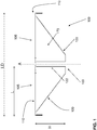
- FIG. 1 shows a schematical view of an antenna device 100 for a base station according to an embodiment of the present invention.
- the antenna device 100 comprises at least two antenna elements 105 and 106 each of which comprises a first radiating element 110 and a corresponding second radiating element 120.
- the second radiating element 120 extends in a height direction along a common center axis A from a foot 103 of the antenna device 100 to its corresponding first radiating element 110.
- the first radiating element 110 and the second radiating element 120 are preferably made of a (single) metal sheet.
- the first radiating element 110 extends in a length direction LD outwards from the common center axis A.
- the length L of the first radiating element 110 defines the maximum supported wavelength.
- each first radiating element 110 has a greater length L than its width W ( Fig. 3 ) and each first radiating element 110 is electrically coupled to its corresponding second radiating element 120 along the length direction LD, so that the second radiating element 120 can contribute to the smaller wavelengths.
- the major contribution of embodiments of the present invention is to reduce the low-band radiating element height, and therefore the overall antenna height H of the antenna device 100 can be reduced by 20-30%, while keeping base station class performance, particularly keeping the relative bandwidth greater than 30%.
- the maximum distance of the radiating system to the reflector is reduced by 20-30%.
- An overall antenna height H below 0.15 ⁇ MAX can be achieved where the ⁇ MAX is the wavelength of the lowest supported frequency.
- each of the second radiating elements 120 may be planar which allows manufacturing the antenna device 100 from a single metal sheet.
- the first radiating elements 110 of different antenna elements 105, 106 respectively have the same shape and/or size.
- the second radiating elements 120 of different antenna elements 105, 106 may respectively have the same shape and/or size.
- each of the first radiating elements 110 may comprise a strip portion 111 which extends outwards from the common center axis in the length direction and at least one bent portion 113, which extends in an angle ⁇ between 10° and 170 °to the length direction, at the outermost part 112 of the strip portion 111 of the first radiating elements 110.
- the bent portion 113 may be built by using bent metal sheet technique.
- a length L2 of the second radiating element 120 at the foot 103 is smaller as the length L1 at its corresponding first radiating element 110.
- An edge 122 along the height direction H of the second radiating element 120 is arranged to be very close to the common center axis A.
- the first upper end 123 of the edge 122 is coupled to the corresponding first radiating element 110.
- Another edge 124 of the second radiating element 120 extends from the foot 103 to a second upper end 125 of the second radiating element 120.
- the second upper end 125 of the second radiating element 120 is coupled to the corresponding first radiating element 110, and comparing with the first upper end 123, the second upper end 125 of the second radiating element 120 is arranged distant from the common center axis A.
- Figure 2 shows a bending edge 114 of each first radiating element 110.
- the bending edge 114 extends in the length direction LD and electrically connects the first radiating element 110 of the antenna element to the corresponding second radiating element 120 of the antenna element.
- the second radiating element 120 and the corresponding first radiating element 110 can be made out of a single metal sheet by cutting a U-shaped incision 126 in the upper part 127 of the second radiating element 120.
- the metal sheet formed the second radiating element 120 and the corresponding first radiating element 110 is bent along a bending edge 128 defined by two upper end points 129 of the U-shaped incision 126 in the second radiating element 120.
- Figure 4 is a perspective view of the antenna device, after the bending, the portion 126' above U-shaped incision 126 forms a part of the strip portion 111 of the corresponding first radiating element 110, and the second radiating element 120 comprises now an opening 121 in place defined by the U-shaped incision 126 and the bending edge 128.
- the first radiating element 110 and the second radiating element 120 of each antenna element can be formed in a single piece.
- the opening 121 is arranged between the first and the second upper ends 123 and 125 of the second radiating element 120 and extends in the length direction LD from a first connection point 171 between the second radiating element 120 and the corresponding first radiating element 110 to a second connection point 172 between the second radiating element 120 and the corresponding first radiating element 110.
- antenna elements can be built using bent metal sheet technology. This allows realizing the second radiating element 120 and the corresponding first radiating element 110 out of one single metallic sheet (without the need for soldering). Embodiments of the present invention thus enable a highly degree of automation in the mass production process with all the advantages of the case.
- each of the second radiating elements 120 may have a substantial triangular portion 173 between its foot and its upper ends (cf. Fig. 1 ).
- a pair of antenna elements 105 and 106 forms a dipole of the antenna and two pairs of antenna elements 105, 106, 107 and 108 arranged around the common center axis.
- the two pairs of said antenna elements 105, 106, 107 and 108 are arranged such that the second radiation elements of a respective pair form a 180° angle and the second radiation elements of two different pairs form a 90° angle. That is to say, preferably, the two pairs of dipoles 105, 106, 107 and 108 are orthogonally or quasi-orthogonally arranged.
- the dipole structure itself to maintain ultra broad band characteristics even reducing the overall height which respect to the ground plane ⁇ 0.15 ⁇ max .
- the first radiating element 110 namely the largest dipole arm dimension, defines the maximum wavelength.
- the galvanically and/or capacitively connected second radiating element 120 gradually contributes to the smaller wavelengths. This enables the radiating elements 110 and 120 to support the wished bandwidth.
- a director element system comprising one or more director elements 140 (e.g. Disk, cross, cylinders, ring etc.) is placed on the antenna elements (dipoles) 105, 106, 107 and 108.
- the function of the director element system is to compensate the capacity to ground effect generated by the height reduction and in this way contributing to the broadband matching.
- the director element system is not directly connected to ground. This has the advantage to introduce also an inductive component and by this way has the clear advantage to significantly improving the radiating element bandwidth.
- an impedance transformer 130 is integrated in the first radiating element 110 around the feed point 116.
- Each antenna element comprises an impedance transformer 130 arranged at the connection point 171 electrically coupling the first radiating element 110 of the antenna element to the corresponding second radiating element 120 of the antenna element.
- the length L of each of the first radiating elements 110 can be at least two times greater than the width W the first radiating elements 110.
- the electrically conducting director element 140 is arranged in the height direction H above the first radiating elements 110 and being supported by dielectric material 150 arranged between the director element 140 and the first radiating elements 110.
- the additional dielectric material 150 is preferably placed e.g. between the 2 directors 140 and/or the directors 140 and the dipoles 105, 106, 107 and 108, and can be used for tuning the bandwidth and as mechanical support for the antenna device 100.
- the director element 140 comprises per first radiating element 110 of the antenna element a corresponding arm 141 extending from the common center axis outwards in the same direction as the corresponding first radiating element 110. Furthermore, at least in some examples, the director system is composed of 2 quasi elliptical orthogonal crosses as shown in Figure 3 .
- Figure 8 shows a perspective view of the arrangement of the dipoles according to an embodiment of the present invention.
- FIG. 2 to 8 a realization example of a dual polarized antenna device (e.g. a low band radiator) is shown in Figures 2 to 8 .
- the antenna device is composed by 2 pairs of radiating elements, each pair forming a dipole, placed 90 degree orthogonal regarding the geometrical center (the common center axis A).
- the two dipoles form a "cross-like" structure which supports the excitation of 2 orthogonal E-field polarizations.
- a bandwidth performance (VSWR ⁇ 1.35 @ relative bandwidth > 35%) can be achieved.
- the second radiating elements 120 are electrically connected to the first radiating elements 110 (the dipole arms).
- the mechanical and electrical material properties of the mounting system for the director 140 and the crosses formed by the dipoles shown in Figures 4 and 8 are chosen to optimize the bandwidth and stability performance.
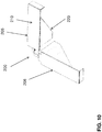
- FIG 10 shows a schematical view of another embodiment of an antenna device 200. Accordingly, two antenna elements 205 and 206, each of which comprises a first radiating element 210 and a second radiating element 220, are arranged such that the second radiating elements of the two antenna elements form a 90° angle.
- Figure 11 schematically shows an arrangement of several antenna devices 100. Accordingly, at least two antenna devices 100 are placed in a line along the length direction LD of the antenna device, and form a line of the antenna device array 300. Preferably, the lines defined by the length direction LD of the antenna device arrays 300 are arranged parallel to each other in a plane.
- Figure 12 schematically shows a further arrangement of several antenna devices 100. Accordingly, at least two antenna devices 100 are placed parallel to each other and form an antenna device group 401. Preferably, at least two such antenna device groups 401 and 402 are arranged, so that a length direction LD1 of the antenna device in a first antenna device group 401 is perpendicular to a length direction LD2 of the antenna device in a second antenna device group 402.
- Figure 13 schematically shows a further arrangement of several antenna devices 100. Accordingly, at least four antenna devices 100 form a rectangular antenna device group and each first radiating element 110 is arranged to be perpendicular to two neighboring first radiating elements, so that the first radiating elements 110 of the at least four antenna devices can form the rectangular antenna device group 500.
- FIG 14 schematically shows an arrangement of several antenna devices 200 according to Figure 10 .
- at least four antenna devices 200 form a rectangular antenna device group 600.
- Each antenna devices 200 forms a right angle 601 of the rectangular antenna device group 600.
- each first radiating element 110 of the four antenna devices 200 is arranged such that the outer end of the each first radiating element 110 faces and is close to the outer end of a first radiating element 110 of a neighboring antenna device 200.
- the proportions between the height H from a reflector to the dipole feet and the length L of dipole arms (the first radiating element 110) are typically 1:4.
- Figure 15 shows a modified antenna according to an unclaimed example.
- Fig. 15 shows a possible capacitive coupling 180 between the first radiating element and 110 the second radiating element 120 by using any suitable fastening means, e.g. clip, latch, hook or bolt fastening.
- any suitable fastening means e.g. clip, latch, hook or bolt fastening.
- the present invention has been described in conjunction with various embodiments as examples as well as implementations. However, other variations can be understood and effected by those persons skilled in the art and practicing the as defined in the appended claims. The mere fact that certain measures are recited in the mutual different dependent claims does not indicate that a combination of these measures cannot be used in an advantageous implementation.
Landscapes
- Engineering & Computer Science (AREA)
- Computer Networks & Wireless Communication (AREA)
- Variable-Direction Aerials And Aerial Arrays (AREA)
- Aerials With Secondary Devices (AREA)
- Details Of Aerials (AREA)
Claims (13)
- Dispositif d'antenne (100) comprenant
au moins deux éléments d'antenne, chaque élément d'antenne comprenant un premier élément rayonnant (110) et un second élément rayonnant correspondant (120) ;
dans lequel chaque second élément rayonnant (120) s'étend dans un sens de hauteur le long d'un axe central commun (A) depuis une extrémité du dispositif d'antenne (100) jusqu'à son premier élément rayonnant correspondant (110) disposé à une autre extrémité du dispositif d'antenne (100) ;
dans lequel chaque premier élément rayonnant (110) s'étend dans un sens de longueur vers l'extérieur depuis l'axe central commun ;
dans lequel chaque premier élément rayonnant (110) a une longueur supérieure à sa largeur ; et
dans lequel chaque premier élément rayonnant (110) est couplé électriquement à son second élément rayonnant correspondant (120) dans le sens de la longueur ;
dans lequel chaque premier élément rayonnant (110) de l'élément d'antenne comprend un bord fléchissant s'étendant dans le sens de la longueur et connectant électriquement le premier élément rayonnant (110) de l'élément d'antenne au second élément rayonnant correspondant (120) de l'élément d'antenne ; et
dans lequel chaque second élément rayonnant (120) comprend une ouverture (121) s'étendant dans le sens de la longueur depuis un premier point de connexion entre le second élément rayonnant (120) et le premier élément rayonnant correspondant (110) jusqu'à un second point de connexion entre le second élément rayonnant (120) et le premier élément rayonnant correspondant (110) ;
dans lequel une aire de l'ouverture (121) est au moins aussi grande qu'une aire d'une partie (126') du premier élément rayonnant (110), la partie (126') s'étendant dans le sens de la longueur depuis le premier point de connexion jusqu'au second point de connexion et dans un sens de la largeur depuis le bord fléchissant (128) jusqu'à un bord (114) du premier élément rayonnant correspondant (110). - Dispositif d'antenne (100) selon la revendication 1,
dans lequel la longueur de chacun des premiers éléments rayonnants (110) est au moins deux fois plus grande que sa largeur. - Dispositif d'antenne (100) selon la revendication 1 ou 2,
dans lequel chacun des seconds éléments rayonnants (120) est plan. - Dispositif d'antenne (100) selon l'une quelconque des revendications 1 à 3,
dans lequel chacun des premiers éléments rayonnants (110) comprend une partie de bande qui s'étend vers l'extérieur depuis l'axe central commun dans le sens de la longueur et au moins une partie fléchie (113) qui s'étend selon un angle ϕ par rapport au sens de la longueur, dans lequel 10° ≤ ϕ ≤ 170°. - Dispositif d'antenne (100) selon l'une quelconque des revendications 1 à 4,
dans lequel pour chaque second élément rayonnant (120) une longueur du second élément rayonnant (120) est inférieure à une extrémité du dispositif d'antenne (100) comparée à une longueur du second élément rayonnant (120) au niveau de son premier élément rayonnant correspondant (110) disposé à l'autre extrémité du dispositif d'antenne (100). - Dispositif d'antenne (100) selon l'une quelconque des revendications 1 à 5,
dans lequel chaque second élément rayonnant (120) comprend un premier bord s'étendant depuis la une extrémité du dispositif d'antenne (100) au moins partiellement dans le sens de la hauteur jusqu'à une première extrémité du second élément rayonnant (120), la première extrémité étant couplée au premier élément rayonnant correspondant (110) ;
dans lequel chaque second élément rayonnant (120) comprend un second bord s'étendant depuis la une extrémité du dispositif d'antenne (100) jusqu'à une seconde extrémité du second élément rayonnant (120), la seconde extrémité étant couplée au premier élément rayonnant correspondant (110) ;
dans lequel, la première extrémité du second élément rayonnant (120) est disposée comparativement plus près de l'axe central commun par rapport à la seconde extrémité du second élément rayonnant (120). - Dispositif d'antenne (100) selon l'une quelconque des revendications 1 à 6,
dans lequel chaque élément d'antenne comprend un transformateur d'impédance (130) disposé à un point de connexion qui couple électriquement le premier élément rayonnant (110) de l'élément d'antenne au second élément rayonnant correspondant (120) de l'élément d'antenne. - Dispositif d'antenne (100) selon l'une quelconque des revendications 1 à 7,
dans lequel chaque élément d'antenne est formé d'un seul bloc. - Dispositif d'antenne (100) selon l'une quelconque des revendications 1 à 8, comprenant en outre : un élément directeur électriquement conducteur (140) disposé dans le sens de la hauteur au-dessus des premiers éléments rayonnants (110) et supporté par un matériau diélectrique (150) disposé entre l'élément directeur (140) et les premiers éléments rayonnants (110).
- Dispositif d'antenne (100) selon la revendication 9,
dans lequel l'élément directeur (140) comprend par premier élément rayonnant (110) de l'élément d'antenne un bras correspondant (141) s'étendant depuis l'axe central commun vers l'extérieur dans le même sens que le premier élément rayonnant correspondant (110). - Dispositif d'antenne (100) selon l'une quelconque des revendications précédentes,
dans lequel les deux éléments d'antenne forment une première paire d'éléments d'antenne et un dipôle (160) du dispositif d'antenne. - Dispositif d'antenne (100) selon la revendication 11, comprenant en outre une seconde paire d'éléments d'antenne disposée autour de l'axe central commun et formant un second dipôle du dispositif d'antenne.
- Dispositif d'antenne (100) selon la revendication 12,
dans lequel les paires desdits éléments d'antenne sont disposées de telle sorte que les seconds éléments rayonnants d'une paire respective forment un angle de 180° et les seconds éléments rayonnants de deux paires différentes forment un angle de 90°.
Applications Claiming Priority (1)
| Application Number | Priority Date | Filing Date | Title |
|---|---|---|---|
| PCT/EP2014/072897 WO2016062356A1 (fr) | 2014-10-24 | 2014-10-24 | Dispositif d'antenne pour système d'antenne de station de base |
Publications (2)
| Publication Number | Publication Date |
|---|---|
| EP3201986A1 EP3201986A1 (fr) | 2017-08-09 |
| EP3201986B1 true EP3201986B1 (fr) | 2018-12-12 |
Family
ID=51799089
Family Applications (1)
| Application Number | Title | Priority Date | Filing Date |
|---|---|---|---|
| EP14789825.8A Active EP3201986B1 (fr) | 2014-10-24 | 2014-10-24 | Dispositif d'antenne pour système d'antenne de station de base |
Country Status (4)
| Country | Link |
|---|---|
| US (1) | US10418691B2 (fr) |
| EP (1) | EP3201986B1 (fr) |
| CN (1) | CN107078383B (fr) |
| WO (1) | WO2016062356A1 (fr) |
Families Citing this family (16)
| Publication number | Priority date | Publication date | Assignee | Title |
|---|---|---|---|---|
| WO2016062356A1 (fr) * | 2014-10-24 | 2016-04-28 | Huawei Technologies Co.,Ltd. | Dispositif d'antenne pour système d'antenne de station de base |
| WO2018103822A1 (fr) * | 2016-12-06 | 2018-06-14 | Huawei Technologies Co., Ltd. | Élément d'antenne à double bande et station de base |
| CN106785366B (zh) * | 2016-12-20 | 2019-05-07 | 中国电子科技集团公司第五十四研究所 | 一种用于卫星共视接收机的全频点测量型天线 |
| WO2019072391A1 (fr) | 2017-10-12 | 2019-04-18 | Huawei Technologies Co., Ltd. | Élément rayonnant ultra compact |
| US12580311B2 (en) | 2017-12-20 | 2026-03-17 | Richwave Technology Corp. | Wireless signal transceiver device with an antenna with at least two feed zones |
| US11367968B2 (en) | 2017-12-20 | 2022-06-21 | Richwave Technology Corp. | Wireless signal transceiver device with dual-polarized antenna with at least two feed zones |
| US10833745B2 (en) | 2017-12-20 | 2020-11-10 | Richwave Technology Corp. | Wireless signal transceiver device with dual-polarized antenna with at least two feed zones |
| US11784672B2 (en) | 2017-12-20 | 2023-10-10 | Richwave Technology Corp. | Wireless signal transceiver device with a dual-polarized antenna with at least two feed zones |
| CN109951205B (zh) * | 2017-12-20 | 2021-04-20 | 立积电子股份有限公司 | 无线信号收发装置 |
| KR102342978B1 (ko) | 2018-01-19 | 2021-12-24 | 삼성전자 주식회사 | 절연체를 포함하는 안테나 모듈 및 이를 포함하는 기지국 |
| MY206799A (en) * | 2018-08-07 | 2025-01-08 | Huawei Tech Co Ltd | Antenna |
| CN111755806A (zh) * | 2019-03-29 | 2020-10-09 | 康普技术有限责任公司 | 用于天线的辐射器和基站天线 |
| CN113036400A (zh) | 2019-12-24 | 2021-06-25 | 康普技术有限责任公司 | 辐射元件、天线组件和基站天线 |
| CN120691090A (zh) | 2020-09-01 | 2025-09-23 | 户外无线网络有限公司 | 基站天线 |
| WO2026046532A1 (fr) | 2024-09-02 | 2026-03-05 | Telefonaktiebolaget Lm Ericsson (Publ) | Dispositif rayonnant destiné à des communications radio |
| US20260088503A1 (en) * | 2024-09-23 | 2026-03-26 | Wistron Neweb Corp. | Antenna device and communication apparatus |
Family Cites Families (10)
| Publication number | Priority date | Publication date | Assignee | Title |
|---|---|---|---|---|
| DE10203873A1 (de) | 2002-01-31 | 2003-08-14 | Kathrein Werke Kg | Dualpolarisierte Strahleranordnung |
| US7053852B2 (en) * | 2004-05-12 | 2006-05-30 | Andrew Corporation | Crossed dipole antenna element |
| DE202004008770U1 (de) * | 2004-06-03 | 2004-08-12 | Kathrein-Werke Kg | Dualpolarisierte Antenne |
| US7639198B2 (en) * | 2005-06-02 | 2009-12-29 | Andrew Llc | Dipole antenna array having dipole arms tilted at an acute angle |
| US8508424B2 (en) * | 2008-11-26 | 2013-08-13 | Andrew Llc | Dual band base station antenna |
| FR2956251B1 (fr) * | 2010-02-05 | 2012-12-28 | Khamprasith Bounpraseuth | Antenne plane a doublet replie |
| US20140028516A1 (en) * | 2012-07-25 | 2014-01-30 | Kathrein, Inc., Scala Division | Dual-polarized radiating element with enhanced isolation for use in antenna system |
| CN103441324B (zh) * | 2013-07-24 | 2016-08-10 | 江苏省东方世纪网络信息有限公司 | 天线 |
| CN103682631A (zh) * | 2013-12-31 | 2014-03-26 | 张家港保税区国信通信有限公司 | 多制式多频段双极化天线 |
| WO2016062356A1 (fr) * | 2014-10-24 | 2016-04-28 | Huawei Technologies Co.,Ltd. | Dispositif d'antenne pour système d'antenne de station de base |
-
2014
- 2014-10-24 WO PCT/EP2014/072897 patent/WO2016062356A1/fr not_active Ceased
- 2014-10-24 EP EP14789825.8A patent/EP3201986B1/fr active Active
- 2014-10-24 CN CN201480082812.3A patent/CN107078383B/zh active Active
-
2017
- 2017-04-21 US US15/493,347 patent/US10418691B2/en active Active
Non-Patent Citations (1)
| Title |
|---|
| None * |
Also Published As
| Publication number | Publication date |
|---|---|
| US10418691B2 (en) | 2019-09-17 |
| EP3201986A1 (fr) | 2017-08-09 |
| CN107078383B (zh) | 2020-01-03 |
| CN107078383A (zh) | 2017-08-18 |
| US20170222306A1 (en) | 2017-08-03 |
| WO2016062356A1 (fr) | 2016-04-28 |
Similar Documents
| Publication | Publication Date | Title |
|---|---|---|
| EP3201986B1 (fr) | Dispositif d'antenne pour système d'antenne de station de base | |
| CN109149131B (zh) | 偶极天线和相关的多频带天线 | |
| US20230114554A1 (en) | Ultra-wide bandwidth low-band radiating elements | |
| JP5738437B2 (ja) | 移動通信基地局用二重偏波アンテナ及びそれを使用する多重帯域アンテナシステム | |
| US10177438B2 (en) | Multi-band antenna arrays with common mode resonance (CMR) and differential mode resonance (DMR) removal | |
| US10003132B2 (en) | Shared-aperture antenna and base station | |
| US20200127389A1 (en) | Antennas including multi-resonance cross-dipole radiating elements and related radiating elements | |
| US9590313B2 (en) | Planar dual polarization antenna | |
| CN107275808B (zh) | 超宽频带辐射器和相关的天线阵列 | |
| US9252490B2 (en) | Multi-band antenna and electronic device provided with the same | |
| CN107078380B (zh) | 无线电子装置 | |
| US20170062940A1 (en) | Compact wideband dual polarized dipole | |
| EP3172797B1 (fr) | Antenne à fentes | |
| CN104067527A (zh) | 双带散布蜂窝基站天线 | |
| JP7058595B2 (ja) | 通信装置 | |
| US9722321B2 (en) | Full wave dipole array having improved squint performance | |
| US10193238B2 (en) | Dipole antenna element with open-end traces | |
| US20030103015A1 (en) | Skeleton slot radiation element and multi-band patch antenna using the same | |
| CN107210518A (zh) | 具有改进的偏斜性能的全波偶极子阵列 | |
| US20250323416A1 (en) | Lowband dipole with improved gain and isolation | |
| KR101523026B1 (ko) | 다중대역 옴니 안테나 | |
| US10916848B2 (en) | Antenna | |
| JP2006229337A (ja) | 多周波共用アンテナ | |
| CN112635982A (zh) | 短路共平面波导馈入双极化宽带天线 | |
| JP2016225792A (ja) | 平面アンテナ |
Legal Events
| Date | Code | Title | Description |
|---|---|---|---|
| STAA | Information on the status of an ep patent application or granted ep patent |
Free format text: STATUS: THE INTERNATIONAL PUBLICATION HAS BEEN MADE |
|
| PUAI | Public reference made under article 153(3) epc to a published international application that has entered the european phase |
Free format text: ORIGINAL CODE: 0009012 |
|
| STAA | Information on the status of an ep patent application or granted ep patent |
Free format text: STATUS: REQUEST FOR EXAMINATION WAS MADE |
|
| 17P | Request for examination filed |
Effective date: 20170503 |
|
| AK | Designated contracting states |
Kind code of ref document: A1 Designated state(s): AL AT BE BG CH CY CZ DE DK EE ES FI FR GB GR HR HU IE IS IT LI LT LU LV MC MK MT NL NO PL PT RO RS SE SI SK SM TR |
|
| AX | Request for extension of the european patent |
Extension state: BA ME |
|
| DAX | Request for extension of the european patent (deleted) | ||
| GRAP | Despatch of communication of intention to grant a patent |
Free format text: ORIGINAL CODE: EPIDOSNIGR1 |
|
| STAA | Information on the status of an ep patent application or granted ep patent |
Free format text: STATUS: GRANT OF PATENT IS INTENDED |
|
| INTG | Intention to grant announced |
Effective date: 20180625 |
|
| GRAS | Grant fee paid |
Free format text: ORIGINAL CODE: EPIDOSNIGR3 |
|
| GRAA | (expected) grant |
Free format text: ORIGINAL CODE: 0009210 |
|
| STAA | Information on the status of an ep patent application or granted ep patent |
Free format text: STATUS: THE PATENT HAS BEEN GRANTED |
|
| AK | Designated contracting states |
Kind code of ref document: B1 Designated state(s): AL AT BE BG CH CY CZ DE DK EE ES FI FR GB GR HR HU IE IS IT LI LT LU LV MC MK MT NL NO PL PT RO RS SE SI SK SM TR |
|
| REG | Reference to a national code |
Ref country code: GB Ref legal event code: FG4D |
|
| REG | Reference to a national code |
Ref country code: CH Ref legal event code: EP |
|
| REG | Reference to a national code |
Ref country code: AT Ref legal event code: REF Ref document number: 1077205 Country of ref document: AT Kind code of ref document: T Effective date: 20181215 |
|
| REG | Reference to a national code |
Ref country code: DE Ref legal event code: R096 Ref document number: 602014037910 Country of ref document: DE |
|
| REG | Reference to a national code |
Ref country code: IE Ref legal event code: FG4D |
|
| REG | Reference to a national code |
Ref country code: NL Ref legal event code: MP Effective date: 20181212 |
|
| REG | Reference to a national code |
Ref country code: LT Ref legal event code: MG4D |
|
| PG25 | Lapsed in a contracting state [announced via postgrant information from national office to epo] |
Ref country code: NO Free format text: LAPSE BECAUSE OF FAILURE TO SUBMIT A TRANSLATION OF THE DESCRIPTION OR TO PAY THE FEE WITHIN THE PRESCRIBED TIME-LIMIT Effective date: 20190312 Ref country code: BG Free format text: LAPSE BECAUSE OF FAILURE TO SUBMIT A TRANSLATION OF THE DESCRIPTION OR TO PAY THE FEE WITHIN THE PRESCRIBED TIME-LIMIT Effective date: 20190312 Ref country code: LT Free format text: LAPSE BECAUSE OF FAILURE TO SUBMIT A TRANSLATION OF THE DESCRIPTION OR TO PAY THE FEE WITHIN THE PRESCRIBED TIME-LIMIT Effective date: 20181212 Ref country code: HR Free format text: LAPSE BECAUSE OF FAILURE TO SUBMIT A TRANSLATION OF THE DESCRIPTION OR TO PAY THE FEE WITHIN THE PRESCRIBED TIME-LIMIT Effective date: 20181212 Ref country code: LV Free format text: LAPSE BECAUSE OF FAILURE TO SUBMIT A TRANSLATION OF THE DESCRIPTION OR TO PAY THE FEE WITHIN THE PRESCRIBED TIME-LIMIT Effective date: 20181212 Ref country code: FI Free format text: LAPSE BECAUSE OF FAILURE TO SUBMIT A TRANSLATION OF THE DESCRIPTION OR TO PAY THE FEE WITHIN THE PRESCRIBED TIME-LIMIT Effective date: 20181212 Ref country code: ES Free format text: LAPSE BECAUSE OF FAILURE TO SUBMIT A TRANSLATION OF THE DESCRIPTION OR TO PAY THE FEE WITHIN THE PRESCRIBED TIME-LIMIT Effective date: 20181212 |
|
| REG | Reference to a national code |
Ref country code: AT Ref legal event code: MK05 Ref document number: 1077205 Country of ref document: AT Kind code of ref document: T Effective date: 20181212 |
|
| PG25 | Lapsed in a contracting state [announced via postgrant information from national office to epo] |
Ref country code: GR Free format text: LAPSE BECAUSE OF FAILURE TO SUBMIT A TRANSLATION OF THE DESCRIPTION OR TO PAY THE FEE WITHIN THE PRESCRIBED TIME-LIMIT Effective date: 20190313 Ref country code: RS Free format text: LAPSE BECAUSE OF FAILURE TO SUBMIT A TRANSLATION OF THE DESCRIPTION OR TO PAY THE FEE WITHIN THE PRESCRIBED TIME-LIMIT Effective date: 20181212 Ref country code: SE Free format text: LAPSE BECAUSE OF FAILURE TO SUBMIT A TRANSLATION OF THE DESCRIPTION OR TO PAY THE FEE WITHIN THE PRESCRIBED TIME-LIMIT Effective date: 20181212 Ref country code: AL Free format text: LAPSE BECAUSE OF FAILURE TO SUBMIT A TRANSLATION OF THE DESCRIPTION OR TO PAY THE FEE WITHIN THE PRESCRIBED TIME-LIMIT Effective date: 20181212 |
|
| PG25 | Lapsed in a contracting state [announced via postgrant information from national office to epo] |
Ref country code: NL Free format text: LAPSE BECAUSE OF FAILURE TO SUBMIT A TRANSLATION OF THE DESCRIPTION OR TO PAY THE FEE WITHIN THE PRESCRIBED TIME-LIMIT Effective date: 20181212 |
|
| PG25 | Lapsed in a contracting state [announced via postgrant information from national office to epo] |
Ref country code: PL Free format text: LAPSE BECAUSE OF FAILURE TO SUBMIT A TRANSLATION OF THE DESCRIPTION OR TO PAY THE FEE WITHIN THE PRESCRIBED TIME-LIMIT Effective date: 20181212 Ref country code: PT Free format text: LAPSE BECAUSE OF FAILURE TO SUBMIT A TRANSLATION OF THE DESCRIPTION OR TO PAY THE FEE WITHIN THE PRESCRIBED TIME-LIMIT Effective date: 20190412 Ref country code: CZ Free format text: LAPSE BECAUSE OF FAILURE TO SUBMIT A TRANSLATION OF THE DESCRIPTION OR TO PAY THE FEE WITHIN THE PRESCRIBED TIME-LIMIT Effective date: 20181212 Ref country code: IT Free format text: LAPSE BECAUSE OF FAILURE TO SUBMIT A TRANSLATION OF THE DESCRIPTION OR TO PAY THE FEE WITHIN THE PRESCRIBED TIME-LIMIT Effective date: 20181212 |
|
| PG25 | Lapsed in a contracting state [announced via postgrant information from national office to epo] |
Ref country code: IS Free format text: LAPSE BECAUSE OF FAILURE TO SUBMIT A TRANSLATION OF THE DESCRIPTION OR TO PAY THE FEE WITHIN THE PRESCRIBED TIME-LIMIT Effective date: 20190412 Ref country code: SK Free format text: LAPSE BECAUSE OF FAILURE TO SUBMIT A TRANSLATION OF THE DESCRIPTION OR TO PAY THE FEE WITHIN THE PRESCRIBED TIME-LIMIT Effective date: 20181212 Ref country code: EE Free format text: LAPSE BECAUSE OF FAILURE TO SUBMIT A TRANSLATION OF THE DESCRIPTION OR TO PAY THE FEE WITHIN THE PRESCRIBED TIME-LIMIT Effective date: 20181212 Ref country code: SM Free format text: LAPSE BECAUSE OF FAILURE TO SUBMIT A TRANSLATION OF THE DESCRIPTION OR TO PAY THE FEE WITHIN THE PRESCRIBED TIME-LIMIT Effective date: 20181212 Ref country code: RO Free format text: LAPSE BECAUSE OF FAILURE TO SUBMIT A TRANSLATION OF THE DESCRIPTION OR TO PAY THE FEE WITHIN THE PRESCRIBED TIME-LIMIT Effective date: 20181212 |
|
| REG | Reference to a national code |
Ref country code: DE Ref legal event code: R097 Ref document number: 602014037910 Country of ref document: DE |
|
| PLBE | No opposition filed within time limit |
Free format text: ORIGINAL CODE: 0009261 |
|
| STAA | Information on the status of an ep patent application or granted ep patent |
Free format text: STATUS: NO OPPOSITION FILED WITHIN TIME LIMIT |
|
| PG25 | Lapsed in a contracting state [announced via postgrant information from national office to epo] |
Ref country code: SI Free format text: LAPSE BECAUSE OF FAILURE TO SUBMIT A TRANSLATION OF THE DESCRIPTION OR TO PAY THE FEE WITHIN THE PRESCRIBED TIME-LIMIT Effective date: 20181212 Ref country code: DK Free format text: LAPSE BECAUSE OF FAILURE TO SUBMIT A TRANSLATION OF THE DESCRIPTION OR TO PAY THE FEE WITHIN THE PRESCRIBED TIME-LIMIT Effective date: 20181212 Ref country code: AT Free format text: LAPSE BECAUSE OF FAILURE TO SUBMIT A TRANSLATION OF THE DESCRIPTION OR TO PAY THE FEE WITHIN THE PRESCRIBED TIME-LIMIT Effective date: 20181212 |
|
| 26N | No opposition filed |
Effective date: 20190913 |
|
| PG25 | Lapsed in a contracting state [announced via postgrant information from national office to epo] |
Ref country code: TR Free format text: LAPSE BECAUSE OF FAILURE TO SUBMIT A TRANSLATION OF THE DESCRIPTION OR TO PAY THE FEE WITHIN THE PRESCRIBED TIME-LIMIT Effective date: 20181212 |
|
| PG25 | Lapsed in a contracting state [announced via postgrant information from national office to epo] |
Ref country code: MC Free format text: LAPSE BECAUSE OF FAILURE TO SUBMIT A TRANSLATION OF THE DESCRIPTION OR TO PAY THE FEE WITHIN THE PRESCRIBED TIME-LIMIT Effective date: 20181212 |
|
| REG | Reference to a national code |
Ref country code: CH Ref legal event code: PL |
|
| PG25 | Lapsed in a contracting state [announced via postgrant information from national office to epo] |
Ref country code: LI Free format text: LAPSE BECAUSE OF NON-PAYMENT OF DUE FEES Effective date: 20191031 Ref country code: LU Free format text: LAPSE BECAUSE OF NON-PAYMENT OF DUE FEES Effective date: 20191024 Ref country code: CH Free format text: LAPSE BECAUSE OF NON-PAYMENT OF DUE FEES Effective date: 20191031 |
|
| REG | Reference to a national code |
Ref country code: BE Ref legal event code: MM Effective date: 20191031 |
|
| PG25 | Lapsed in a contracting state [announced via postgrant information from national office to epo] |
Ref country code: BE Free format text: LAPSE BECAUSE OF NON-PAYMENT OF DUE FEES Effective date: 20191031 |
|
| PG25 | Lapsed in a contracting state [announced via postgrant information from national office to epo] |
Ref country code: FR Free format text: LAPSE BECAUSE OF NON-PAYMENT OF DUE FEES Effective date: 20191031 Ref country code: IE Free format text: LAPSE BECAUSE OF NON-PAYMENT OF DUE FEES Effective date: 20191024 |
|
| PG25 | Lapsed in a contracting state [announced via postgrant information from national office to epo] |
Ref country code: CY Free format text: LAPSE BECAUSE OF FAILURE TO SUBMIT A TRANSLATION OF THE DESCRIPTION OR TO PAY THE FEE WITHIN THE PRESCRIBED TIME-LIMIT Effective date: 20181212 |
|
| PG25 | Lapsed in a contracting state [announced via postgrant information from national office to epo] |
Ref country code: HU Free format text: LAPSE BECAUSE OF FAILURE TO SUBMIT A TRANSLATION OF THE DESCRIPTION OR TO PAY THE FEE WITHIN THE PRESCRIBED TIME-LIMIT; INVALID AB INITIO Effective date: 20141024 Ref country code: MT Free format text: LAPSE BECAUSE OF FAILURE TO SUBMIT A TRANSLATION OF THE DESCRIPTION OR TO PAY THE FEE WITHIN THE PRESCRIBED TIME-LIMIT Effective date: 20181212 |
|
| PG25 | Lapsed in a contracting state [announced via postgrant information from national office to epo] |
Ref country code: MK Free format text: LAPSE BECAUSE OF FAILURE TO SUBMIT A TRANSLATION OF THE DESCRIPTION OR TO PAY THE FEE WITHIN THE PRESCRIBED TIME-LIMIT Effective date: 20181212 |
|
| PGFP | Annual fee paid to national office [announced via postgrant information from national office to epo] |
Ref country code: GB Payment date: 20250904 Year of fee payment: 12 |
|
| PGFP | Annual fee paid to national office [announced via postgrant information from national office to epo] |
Ref country code: DE Payment date: 20250902 Year of fee payment: 12 |