EP3202029B1 - Tragbare fotovoltaische solaranordnung - Google Patents
Tragbare fotovoltaische solaranordnung Download PDFInfo
- Publication number
- EP3202029B1 EP3202029B1 EP15847048.4A EP15847048A EP3202029B1 EP 3202029 B1 EP3202029 B1 EP 3202029B1 EP 15847048 A EP15847048 A EP 15847048A EP 3202029 B1 EP3202029 B1 EP 3202029B1
- Authority
- EP
- European Patent Office
- Prior art keywords
- modules
- array
- flexible connector
- module array
- condition
- Prior art date
- Legal status (The legal status is an assumption and is not a legal conclusion. Google has not performed a legal analysis and makes no representation as to the accuracy of the status listed.)
- Active
Links
Images




Classifications
-
- H—ELECTRICITY
- H02—GENERATION; CONVERSION OR DISTRIBUTION OF ELECTRIC POWER
- H02S—GENERATION OF ELECTRIC POWER BY CONVERSION OF INFRARED RADIATION, VISIBLE LIGHT OR ULTRAVIOLET LIGHT, e.g. USING PHOTOVOLTAIC [PV] MODULES
- H02S30/00—Structural details of PV modules other than those related to light conversion
- H02S30/20—Collapsible or foldable PV modules
-
- H—ELECTRICITY
- H02—GENERATION; CONVERSION OR DISTRIBUTION OF ELECTRIC POWER
- H02S—GENERATION OF ELECTRIC POWER BY CONVERSION OF INFRARED RADIATION, VISIBLE LIGHT OR ULTRAVIOLET LIGHT, e.g. USING PHOTOVOLTAIC [PV] MODULES
- H02S10/00—PV power plants; Combinations of PV energy systems with other systems for the generation of electric power
- H02S10/40—Mobile PV generator systems
-
- H—ELECTRICITY
- H02—GENERATION; CONVERSION OR DISTRIBUTION OF ELECTRIC POWER
- H02S—GENERATION OF ELECTRIC POWER BY CONVERSION OF INFRARED RADIATION, VISIBLE LIGHT OR ULTRAVIOLET LIGHT, e.g. USING PHOTOVOLTAIC [PV] MODULES
- H02S40/00—Components or accessories in combination with PV modules, not provided for in groups H02S10/00 - H02S30/00
- H02S40/30—Electrical components
- H02S40/36—Electrical components characterised by special electrical interconnection means between two or more PV modules, e.g. electrical module-to-module connection
-
- H—ELECTRICITY
- H10—SEMICONDUCTOR DEVICES; ELECTRIC SOLID-STATE DEVICES NOT OTHERWISE PROVIDED FOR
- H10F—INORGANIC SEMICONDUCTOR DEVICES SENSITIVE TO INFRARED RADIATION, LIGHT, ELECTROMAGNETIC RADIATION OF SHORTER WAVELENGTH OR CORPUSCULAR RADIATION
- H10F19/00—Integrated devices, or assemblies of multiple devices, comprising at least one photovoltaic cell covered by group H10F10/00, e.g. photovoltaic modules
- H10F19/90—Structures for connecting between photovoltaic cells, e.g. interconnections or insulating spacers
-
- F—MECHANICAL ENGINEERING; LIGHTING; HEATING; WEAPONS; BLASTING
- F24—HEATING; RANGES; VENTILATING
- F24S—SOLAR HEAT COLLECTORS; SOLAR HEAT SYSTEMS
- F24S30/00—Arrangements for moving or orienting solar heat collector modules
- F24S2030/10—Special components
- F24S2030/16—Hinged elements; Pin connections
-
- Y—GENERAL TAGGING OF NEW TECHNOLOGICAL DEVELOPMENTS; GENERAL TAGGING OF CROSS-SECTIONAL TECHNOLOGIES SPANNING OVER SEVERAL SECTIONS OF THE IPC; TECHNICAL SUBJECTS COVERED BY FORMER USPC CROSS-REFERENCE ART COLLECTIONS [XRACs] AND DIGESTS
- Y02—TECHNOLOGIES OR APPLICATIONS FOR MITIGATION OR ADAPTATION AGAINST CLIMATE CHANGE
- Y02E—REDUCTION OF GREENHOUSE GAS [GHG] EMISSIONS, RELATED TO ENERGY GENERATION, TRANSMISSION OR DISTRIBUTION
- Y02E10/00—Energy generation through renewable energy sources
- Y02E10/50—Photovoltaic [PV] energy
Definitions
- This invention relates to portable or redeployable arrays of solar photovoltaic (PV) modules for the purpose of power generation.
- PV solar photovoltaic
- Solar PV modules are well known as devices that convert light energy (electromagnetic radiation) directly into usable electric energy via a photoelectric effect. The process of conversion is well known.
- Solar PV modules can be formed as mountable panels and in that form, the modules have been installed extensively in the domestic and commercial markets, usually on the roofs of domestic dwellings and commercial buildings, to supplement electricity supply from the normal grid supply, or to feed back into the normal grid supply.
- PV modules comprise a plurality of PV cells that are connected electrically and physically in various configurations to form the PV module (or 'solar panel'), while the module also comprises structural support and environmental encapsulation of the PV cells.
- PV modules are typically installed on mounting structures and electrically interconnected to form PV arrays, along with other balance of system components (BoS) such as inverters, electrical reticulation, switchgear and protection to complete the system.
- BoS system components
- PV arrays can be designed and constructed in a variety of ways, however common to all PV arrays is the goal of minimising the cost per unit of energy delivered by the PV system.
- the two main determinants of the cost of energy from a PV system are capital cost and energy generation.
- PV module In contrast, energy generation from a PV system is highly dependent upon the PV array configuration - that is, the 3D spatial orientation of the modules in the PV array.
- a PV module generates optimal output when it is positioned at an angle which is normal to the incidence of the sun's rays at any given time. Due to the diurnal and seasonal movement of the sun, this results in the modules of a PV array being either mounted on a structure which tracks the path of the sun diurnally and/or seasonally to achieve optimal generation most or all of the time, or otherwise the modules are fixed at a tilt and orientation which in a compromise, nevertheless achieves the maximum possible annual generation without tracking.
- PV arrays that are installed to track the path of the sun include dual axis tracking PV arrays (which track diurnally and seasonally) which have the highest capital cost but the highest generation yield, single axis inclined tracking (which track diurnally but not seasonally), and single axis horizontal tracking (which also track diurnally but not seasonally).
- Non tracking PV arrays are fixed arrays which provide the lowest cost but also lowest energy generation. These include flat arrays, whereby the modules are laid out in a planar configuration and more recently, East-West (EW) PV arrays (which are a subset of fixed PV arrays).
- EW East-West
- Tracking PV arrays seek to increase the energy yield of a PV array by ensuring the PV modules are orientated as close to an angle normal to the radiation of the sun as possible at any given time. This is achieved by a mechanical (or sometimes hydraulic) mounting structure which moves the PV modules in one or two axis over the course of the sunlight hours.
- a fixed PV array currently represents an effective compromise of cost, complexity and operational risk of the PV array with energy generation.
- the PV modules remain fixed for the life of the PV system, therefore an orientation must be chosen which achieves the maximum generation possible from the fixed PV array in the absence of tracking.
- the orientation of the PV array (including the tilt angle) is often dictated by the structure to which the PV array is fixed. As this is often a roof, often the orientation is not optimal depending on which way the roof faces and the incline of the roof.
- An EW configuration essentially splits a planar PV array into two sub-arrays of PV modules, one sub-array orientated towards the east and the other sub-array orientated towards the west.
- the modules can be arranged in rows, or in end-to-end connection or alignment, with each row arranged as a series of successive triangles each made up of one east-facing and one west-facing module.
- An EW PV array achieves a capital cost lower than a fixed PV array, due to reduced structural requirements (due to lower wind loadings and more integrated structure), reduced foundation requirements, and reduced array footprint.
- the downside though is the reduced energy generation due to the non-optimal fixed orientation. Until recently, the cost benefit of the reduced structural requirements did not justify the reduced energy generation, however as PV module cost continues to fall, this balance has changed and in certain applications the EW approach can result in a lower cost of energy than conventional fixed PV arrays.
- the present invention is directed to that form of PV array.
- Pre-assembled PV arrays have advantages in relation to reduced installation labour and construction timeframe requirements, while portable PV arrays enable use of PV systems in shorter term applications at different locations.
- the first is a collection of low-voltage portable systems designed for use whilst camping, in military exercises, or essentially anywhere where temporary or short term energy generation is required. These systems typically are of small power generation capability, physically small and have the PV modules oriented on a single plane to maximize energy yield (i.e not EW configuration). This group of products is largely irrelevant to the present invention.
- the second group of products which are more relevant to the invention, are larger scale pre-assembled PV arrays that include a folding structure to enable the PV array to be portable.
- These systems are typically more expensive than a conventional fixed or EW PV array and have PV modules mounted to a complex sub-structure which includes articulated joints for unfolding the array of modules.
- These systems are planar systems rather than EW systems.
- Portable systems of the second group of products are costly and therefore do not provide low cost of energy. They are therefore typically only used in bespoke applications which can justify the added cost necessary to achieve the desired portability of the PV system.
- JPS64-11373 describes a portable solar panel array with each panel supported on a flexible substrate that is electrically insulating, lightweight, high flexibility and high strength.
- the substrate is supported on a rigid frame 1 to move between an open and closed position.
- a setting rod 12 is manually attached between the eyelets 11 rigidly secured to the frame members 1. The angle between each pair of folded panels 1A and 2 is determined by the length of the setting rod 12, engaged between the eyelets 11.
- EP 2843320 describes a carrier for solar panels.
- the carrier has frame members 2A, 2B and 2C, that are hingedly connected to each other, so the panels 1 can be moved from a closed configuration to an open configuration using hinge joints 3A and 3B.
- the hinged members 2A and 2B are connected via connecting elements 14A and 14B.
- the connecting elements 14A and 14B have an articulated joint 5, and pivotal connections 6 to the frame members 2A and 2B respectively. In the unfolded state, the connecting elements 14A and 14B are at 180° to each other. Thereby setting the relative angle between the solar panels 1.
- Each of the upper hinges 3A have two pairs of the connecting elements 14B and 14B-, while each of the lower hinges 3B and 3B- have another pair of connecting members that are also articulated about the middle (see 18A and 18B of Figure 4A ). This controls the relative angle of the panels in the open or deployed state.
- CN201509167 discloses, with reference to the Figures, a telescopic solar portable power source flanked on each side by a pair of retractable support frames 1 and 2.
- the pair of retractable support frames are hinged to each other as well as the solar panels 3, also hinged to each other to extend from a base vertically upwards, or collapse into, flat facing configuration for storage and transport. Deploying the panels is achieved by compressing the articulated hinges in the support frames 1 and 2 towards the opposing hinge in the connected solar panels 3.
- a portable PV array comprising:
- the present invention provides a portable PV module array that can be stored and transported in the closed condition, and can be erected into the open condition for use in a suitable location.
- the portability of the PV module array is beneficial for permanent installations, as the array can be preassembled at the point of manufacture and installed easily at the point of installation, or the array can be one which is commissioned and decommissioned on a regular or semi-regular basis. That is, the array could be installed for temporary use at one location, then either returned to a storage location, or transported to a new location.
- the PV array can be shifted from the open condition to the closed condition for transport either back to the storage location or to the new location at which it is to be installed. Upon arrival at that new location, the array can be shifted from the closed condition to the open condition and connected for electricity generation and use.
- PV array An important feature of a PV array is the flexible connection that restricts the extent to which the PV modules can open relative to one another.
- the extent which the modules can be opened is limited by the point at which the flexible connector becomes tensioned or taut. Once the flexible connector has reached that state, then no further unfolding movement between the two modules of the PV array can take place. Accordingly, the maximum open angle between the PV modules of the PV array can be set at the point of manufacture of the PV array, so that upon installation of the PV array at an installation site, there is no necessity for installation personnel to set the angle between the PV modules. Rather, the angle is pre-set as discussed above by the position at which the flexible connector becomes tensioned.
- the flexible connector could be adjustable, to adjust the angle between the PV modules and the flexible connector could include markings in order to identify the angle which exists between the PV modules at a particular length setting of the flexible connector.
- the flexible connector could, for example, include a threaded adjuster that allows the connector to be shortened or lengthened and thus allows the angle between the PV modules to be decreased or increased.
- the flexible connector can be made of any suitable material such as, steel wire or cable, other metal wire or cable, synthetic, plastic or rubber cord, rope, or fabric, in the form of a fabric tether.
- suitable material such as, steel wire or cable, other metal wire or cable, synthetic, plastic or rubber cord, rope, or fabric.
- the preference is that the flexible connector be flexible but substantially inelastic or inextensible.
- a flexible connector advantageously can significantly reduce the structure required to position the PV modules as required in an EW orientation.
- Prior art arrangements include costly and heavy structures which are largely omitted in the present invention.
- the flexible connector provides a simple mechanism by which the PV modules can be folded between the closed and open conditions, which advantageously in some forms of the invention, can be a manual operation principally as a result of the use of the flexible connector.
- the flexible connector can be left loose or slack when the PV modules are in the closed condition, or the connector can be supported so that it is retained relative to the modules in a specific position.
- the connector might be adhered, such as by an adhesive tape, to a proximate surface of the PV modules, so that the connector is neatly stored during storage and transport of the PV array.
- the tape might be allowed to fail during folding movement of the PV modules to the open condition.
- clips might be provided into which the flexible connector can be secured, again for the purpose of securing the flexible connector during storage and transport.
- the clips could be attached to structural parts of the PV modules.
- a spring arrangement can be provided whereby the connector extends through or is otherwise connected to a spring that is attached to either a PV module, or to a connector between the modules, with the arrangement being such that as the modules move to the open condition, the spring extends as the flexible connector goes into tension. Conversely, as the modules are shifted from the open condition to the closed condition, the spring retracts, lifting the flexible connector upwardly and securing the connector for storage and transport.
- connection of the modules along adjacent end edges can be by any suitable manner.
- the connection must allow movement of the modules relative to one another between the closed and open conditions, but this could be achieved in any suitable manner, such as by a flexible plastic, rubber or fabric hinges, or by a standard metal hinge which comprises two parts that are separately connected to the facing end edges of adjacent PV modules and a pin that extends between the parts and allows them to pivot relative to one another in a hinging manner.
- the connection could alternatively be simply by rope, cable or chain.
- the invention embodies any suitable connection that allows the required relative movement between the modules to go from the closed condition to the opened condition.
- connections between end edges of modules differ, meaning that the connectors which are formed at the peaks between adjacent end edges, are different to the connections that are formed at the troughs.
- One reason for this is that it is advantageous for the flexible connector to connect to the PV array via connections made at the troughs of the modules, so that the connector is adjacent the surface on which the array is mounted in an open and installed condition.
- the connectors at the troughs can include facility to connect to the flexible connector whereas the connectors at the peaks do not need that facility.
- a PV array according to the invention can include an initial array comprising a row of at least two modules that are connected at end edges, and duplicate rows of arrays can be connected to side edges of the initial array.
- the rows of the array can include any number of modules connected at end edges and any number of rows of modules can be connected laterally. In that arrangement, only a single flexible connector need be applied to one row of modules between opposite ends of the row, while the adjacent rows do not require a separate flexible connector. Of course further flexible connectors can be provided as desired for structural integrity. In some arrangements, each of the outermost rows can include a flexible connector, while the interior rows will not include a flexible connector.
- the flexible connector can advantageously be used to earth the PV modules and this can be by extending a cable from a module into connection with the flexible connector 22.
- the flexible connector is a conductive connector, such as steel or other metal wire or cable.
- the invention extends from a minimum of two PV modules to a greater number.
- a plurality of PV module arrays that comprise only two PV modules can be assembled together to form a greater overall PV array, and in such an arrangement, the individual two PV module arrays can be assembled into an array without connection together, or they can be connected to each other on site.
- the PV modules can be manufactured with connectors along the free end edges, ie those edges that are spaced from or remote from the edges of the PV modules at the apex that are connected together, or the PV modules can be manufactured with connectors along the side edges, so that on site connection between the individual PV arrays can be made.
- connections could be of any suitable form and could be very simple, such as a pin connection, whereby a pin is connected to one edge of one PV module and a sleeve or tube is connected to another PV module so that insertion of the pin into the sleeve is sufficient to connect the PV modules of the individual PV arrays together temporarily.
- the invention extends to greater number of PV modules that are connected in rows or end-to-end along end edges and arrays of six, eight, ten or more PV modules connected in rows is contemplated as being appropriate in the present invention.
- the number of PV modules per PV array will be limited by the bulk of the PV array in the closed condition given that transport vehicles will have an upper size or weight restriction, but multiple vehicles can transport multiple PV arrays so that the overall size of the array can increase to whatever size is required.
- FIG 1 is a perspective view of a portable PV array 10 according to one embodiment of the invention and is shown in an open or operational condition in which modules of the array are disposed in a triangular configuration to form an EW array of the kind described above.
- the array 10 includes a first planar PV module 11 and a second planar PV module 12. All of the modules described herein will have the same construction which is rectangular and planar. The first and second modules 11 and 12 form part of a greater or larger PV array 10, but discussion will firstly focus on the modules 11 and 12 only.
- Each of the modules 11 and 12 are of rectangular configuration, so that each defines a generally rectangular edge, the dimensions of which are about the same for each module 11 and 12.
- the edges comprise a pair of substantially parallel end edges 13 and 14 of the module 11 and end edges 15 and 16 of the module 12, and side edges 17 and 18. It can be seen, in particular with respect to the module 11, that the modules comprise a grid or matrix of PV cells 19.
- FIG. 1 is a view of the PV array 10 but shown in a closed or stacked condition as would be adopted for storage or transport of the array 10.
- hinges 20 can be seen connecting the end edges 14 and 15 of the modules 11 and 12 together.
- Figures 1 and 2 thus show the array 10 in both the open ( Figure 1 ) and the closed ( Figure 2 ) conditions.
- the modules 11 and 12 are stacked together in a generally parallel and close facing relationship, with the end and side edges of the modules 11 and 12 in general alignment.
- the modules 11 and 12 are disposed relative to one another at an angle ⁇ , which in Figure 1 is in the region of about 160°.
- the angle could of course be different to this and can be altered by the length of connector 22 extending between the bars 23 and 24. It is evident from Figure 1 , that in the opened condition, the modules 11 and 12 define a triangular configuration. This thus forms the modules 11 and 12 in an East-West configuration which has advantages compared to planar PV arrays as discussed above.
- the transition of the modules 11 and 12 from the closed condition of Figure 2 to the open condition of Figure 1 is via folded or hinged movement about the end edges 14 and 15 of the modules 11 and 12, facilitated by the hinges 20. That folding movement could continue until the modules 11 and 12 arrived at a flat or planar condition relative to each other, except that the array 10 includes a flexible connector that connects with connection points associated with each of the modules 11 and 12 and that is tensioned in the opened condition as shown. It is the flexible connector that prevents the modules 11 and 12 from unfolding all the way to a flat or planar condition and which thus maintains the modules in the triangular configuration shown in Figure 1 .
- connection points associated with each of the modules 11 and 12 are tubes, bars or posts 23 and 24, that extend parallel to the end edges 13 and 16 of the respective modules 11 and 12.
- the bars 23 and 24 are connected to the end edges 13 and 16 via a pair of sleeves 25 and 26 at each of the end edges 13 and 16 and as can be seen in Figure 1 .
- the sleeves 25 and 26 are also seen in Figures 4 and 5 and those figures also show that the sleeves connect to the end edge of the modules via brackets 27.
- the brackets can be fixed to the end edges by screws for example.
- the bars 23 and 24 extend beyond the side edges 17 of each of the modules 11 and 12 for connection of the flexible connector 22.
- Figure 4 is an underneath perspective view of the PV array shown in Figure 2 which shows that extension while Figure 5 also shows the extension.
- PV arrays which include greater number of PV modules are within the scope of the present invention.
- PV modules 30 to 33 can be provided to extend the PV array to form an elongate row of PV modules so that the PV array defines a series of alternating peaks and troughs.
- the modules 11, 30 and 32 could be east-facing modules, while the modules 12, 31 and 33 could be west-facing modules.
- the modules 30 to 33 repeat the connection arrangement of the modules 11 and 12, so that the end edge 16 of the module 12 and the end edge of 34 of the module 30 connect via the bar 24. Moreover, the facing end edges of the modules 30 and 31 which are located at the peak 35 are connected by hinges 36 (see Figure 2 ) which are the same as the hinges 20.
- the end edges of the modules 31 and 32 which are in facing relationship at the trough 37 are hingedly connected by the bar 38 and this form of connection at the respective peaks and troughs is repeated throughout the length of the PV array. While the array 10 is shown to have six modules, 11, 12 and 30 to 33, any number of modules could be connected in the manner shown and described, so that arrays of eight, ten or greater numbers of modules, connected end to end or in rows, can be provided.
- hinges 20 and 36 which are described in relation to Figures 1 and 2 could be employed rather than the bars 23, 24 and 38, or alternatively, that the hinges 20 and 36 could be replaced by bars which are of the same configuration and connection as the bars 23, 24 and 38.
- the provision of the bars 23, 24 and 38 is to provide connection for the flexible connector 22, and as shown in Figure 1 , that connector extends from the bar 23, in connection with the bars 24 and 38, and finally to the bar 39.
- the bars 23, 24, 38 and 39 also assist the provision of a second and additional PV module to be placed or connected laterally side by side the modules 11, 12 and 30 to 33 as described above.
- further modules 40 to 45 can be included in the PV array 10 to increase the surface area of the array 10 and common connections to the earlier modules described above can be made via the bars 23, 24, 38 and 39.
- the bars 23, 24, 38 and 39 can extend fully from one side of the PV modules comprising modules 11, 12 and 30 to 33, to the other side of the modules 40 to 45, or separate bars could extend through the respective rows of PV modules and be connected at free ends at the junction between facing side edges of the PV modules.
- the modules 40 to 45 are not required to be connected to the modules 11, 12 and 30 to 33, although connections can be made if desired.
- facing side edges of the modules 11 and 40 can be connected, while the hinges 20 formed at the facing end edges 14 and 15 of the modules 11 and 12 can be modified for connection with the facing end edges of the modules 40 and 41.
- Figure 3 illustrates this form of arrangement, whereby a stack of modules 46 is connected via fixed connectors 47 to an adjacent stack of modules 48.
- the modules need not be connected to the modules 11, 12 and 31 to 33, other than through the bars 23, 24, 38 and 39.
- the modules 40 to 45 can simply be placed next to the modules 11, 12 and 31 to 33 and have no connection at all between them.
- the benefit of connecting the modules in the PV array shown in Figures 1 and 2 is that movement between the open and closed conditions is quicker that two separate rows of modules.
- the flexible connector 22 can extend continuously between the bars 23 and 39, or separate connectors can extend between adjacent bars, such as between bars 23 and 24 and then separately between bars 24 and 38 and bars 38 and 39.
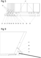
- Figure 5 is a view just of the bars 23, 24, 38 and 39 of the array 10, shown in the closed condition of Figure 2 . In that position, loops 50 can be seen extending about each of the bars, and these include a crimp connection 51 by which opposite ends of discreet lengths of the flexible connector 22 can be connected.
- a portion of the connector 22 which extends between the bars 23 and 24 is shown, while the same reference number is used to show flexible connector sections extending between the bars 24 and 38 and 38 and 39.
- the flexible connector 22 could extend through the respective bars of the array 10 and a grub screw could be screwed into engagement with the connector within the bars so as to locate the connector relative to the bars.
- the flexible connector 22 could cooperate with a hinge that is provided at the junction between adjacent PV modules at the trough between those modules, and Figure 10 illustrates the PV modules 12 and 30, and 41 and 42 of the array 10 with an example alternative arrangement applied.
- two hinges 86 are illustrated.
- the flexible connector 22 is shown extending up between the junction of the PV modules 12 and 30 and the through the bolt 87 that extends through the hinge 86.
- An opening is formed in the shank of the bolt 87 for passage of the flexible connector 22.
- the bolt 87 also includes a threaded bore or opening through the shank of the bolt laterally to the opening through which the flexible connector 22 extends and a grub screw can be is screwed into the threaded opening and into engagement with the portion of the flexible connector 22 within the opening. By this arrangement, the position of the flexible connector 22 can be secured.
- FIG 11 shows a further example of a connection between modules 53 and 54, whereby the flexible connector 55 is a flat connector that is fixed by a bolt 58 to the side edges 56 and 57 of the respective modules 53 and 54.
- the bolt 58 is thus a connector attached along a free edge of the module 54.
- the length of the flexible connector between the bars can be adjusted, such as by a screw adjuster, or by a cleat arrangement.
- the length of the flexible connector between the bars be set when the PV array is manufactured, as this removes one element or step of installation when the array is to be employed on site.
- the flexible connector shown in the drawings could be metal wire, rope, or a woven fabric.
- Plastic cord could alternatively be employed, as could other materials or products that meet the requirement for the invention, which is that they must be able to slacken for the PV modules to be folded to the closed condition, and to remain taut and tensioned in the opened condition.
- a major feature of the invention is the manner in which the PV modules can be folded into the closed position from the opened position, and then unfolded back to the opened condition.
- This allows the PV array to be portable and easily installed and removed.
- Figures 2 , 3 and 4 show the PV array in the closed condition in which the array can be stored and transported. It will be evident that the compact nature of the array in the closed condition will allow much greater length of array to be stored and transported in a compact condition, and then installed at an installation site to provide significant area for capture of sunlight or electromagnetic radiation.
- the array 10 can be manufactured and preassembled completely in a manufacturing facility, and in a basic form of the invention, no additional structural material is required when the array is to be opened for use at an installation site. It is expected however, that ballast will be applied to the array 10 after installation, and in the illustrated figures, this can be fixed to the free ends of the bars and can be in the form of sand bags or concrete blocks, or the free ends of the bars can be pegged down.
- the PV array can be manufactured with all balance of system components in place, or they can be installed as part of the installation process.
- the flexible connector 22 maintains the modules in the triangular or east-west configuration that is required, and the preassembly of the flexible connector to the modules means that there is no requirement for the east-west orientation to be set by installation personnel. Rather, it sets automatically when the modules are shifted to the open position. It is to be noted that for installation purposes, wheels or skids such as structural feet, can be attached to the bars 23, 24, 38 and 39.
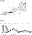
- Figures 6 to 8 illustrate the array 10 in a partially open condition.
- the array 10 has been extended lengthwise, to include a greater number of modules than that shown in Figures 1 and 2 . This illustrates the flexibility with which additional modules can be included in an array as the power requirements of an installation increase.
- a PV array 60 comprising modules 61 to 67, and further modules 68 in a closed and generally parallel configuration.
- the array 60 includes two sets of lengthwise extending rows of modules which are connected laterally or side by side along the bars 69 to 75.
- the flexible connector 77 between the modules 61 and 62 is in tension and is therefore taut.
- the connectors 78 and 79 are slack, because the respective modules that those connectors extend between are not yet in the open condition.
- the interior angle between the modules 61 and 62 is greater than between the modules 63 and 64 and is greater again than between the modules 65 and 66.
- the modules 68 are yet to commence shifting to the open position and those modules remain in a generally parallel and close facing relationship.
- the array 60 can be lifted from the transport vehicle that has transported the array to the installation site, and the array 60 can thereafter be placed on the installation surface, which might be a roof, or an outdoor stage, or a park etc.
- the bar 69 can be engaged either manually or with an installation device, and can be pulled away from the stack of PV modules so that the modules 61 and 62 are first shifted from the generally close facing and parallel relationship of the other modules.
- prototypes tested to date show that this can be a manual process.
- the process can be such that the modules 61 and 62 are taken to the open position before the modules 63 and 64 are moved from the closed condition.
- the modules 61 to 68 shown in Figures 6 to 8 would have edge or external dimensions of 1 metre x 2 metres per module so that with the array 60 fully extended in the open condition, the length of the array would be in the order of 24 metres.
- the dimensions of the array are in the order of .9 metres long x 2 metres high x 2 metres wide and the weight of the array would be in the region of 800 kg.
- the flexible connectors 77, 78 and 79 shown in Figures 6 to 8 are shown in the fully extended condition (connector 77), in a still slightly slack condition (connector 78) and in a completely slack condition (connector 79).
- the connector 78 is attached by a spring 80 to the peak 81 between the modules 63 and 64 and that connection can be for example, to a hinge that is positioned at the peak 81.
- the spring thus extends as the modules 63 and 64 move towards the open condition, and it contracts and lifts the connector 78 as the modules 63 and 64 move to the closed condition.
- the connector 78 is neatly stored in the closed condition, but fully able to assume a tensioned state in the opened condition.
- Alternative arrangements include clips provided on edges of the modules to which the flexible connector can be secured in the closed condition of the array, while a less permanent arrangement can involve using adhesive to attach the connectors to a surface of the modules when the array is initially assembled and the adhesive will break or shear when the modules are placed in the open condition. That arrangement obviously needs to be replenished each time the modules are returned to the closed condition, but it is a simple step and therefore potentially acceptable.
- FIG. 10 It has been discussed above that lateral connection of further rows of arrays to side edges of an initial array can broaden the surface area of the array overall.
- the figures all show arrays in which a pair of modules are positioned side by side (for example see modules 11 and 40 in Figures 1 and 2 ). Further side additions to the arrays 10 and 60 can be made subject to the ability to transport the arrays. It will be appreciated that the dimensions of an array in the closed condition will increase as the number of modules is added end to end, as well as side to side.
- Figure 9 is a view of one corner of the PV module 12 of Figure 1 , and therefore also shows one section of the bar 24. In addition to those features, Figure 9 shows an earthing cable 85 that extends from the module 12 into connection with the flexible connector 22.
- the flexible connector 22 is a conductive connector, such as steel or other metal wire or cable, and therefore the module 12 can be earthed by electrical connection to the connector 22.
Landscapes
- Photovoltaic Devices (AREA)
- Life Sciences & Earth Sciences (AREA)
- Sustainable Development (AREA)
- Electromechanical Clocks (AREA)
Claims (14)
- Tragbare PV-Modulanordnung (10), umfassend:mindestens vier ebene PV-Module (11, 12), die eine allgemein quadratische oder rechteckige Konfiguration aufweisen, sodass jedes PV-Modul (11, 12) eine allgemein quadratische oder rechteckige Kante mit im Wesentlichen denselben Abmessungen definiert und ein Paar von im Wesentlichen parallelen Endkanten (13, 14, 15, 16) und ein Paar von im Wesentlichen parallelen Seitenkanten (17, 18) umfasst,wobei die PV-Module (11, 12) entlang benachbarter Endkanten (14, 15) verbunden sind und relativ zueinander um die verbundenen Endkanten (14, 15) zwischen einem geschlossenen Zustand und einem offenen Zustand faltbar sind, wodurch:die PV-Module (11, 12) im geschlossenen Zustand in einer allgemein parallelen und dicht gegenüberliegenden Beziehung zusammengestapelt sind, wobei die Kanten der PV-Module (11, 12) allgemein aneinander ausgerichtet sind, unddie PV-Module (11, 12) im offenen Zustand in einem Winkel (β) zueinander angeordnet sind, sodass die PV-Modulanordnung (10) eine dreieckige Konfiguration definiert, in der die PV-Module (11, 12, 30, 31) in einer Reihe von abwechselnden Spitzen und Tälern verbunden sind, dadurch gekennzeichnet, dasseine Faltbewegung der PV-Module (11, 12) aus dem geschlossenen Zustand in den offenen Zustand gegen eine Bewegung über den offenen Zustand hinaus durch einen flexiblen Verbinder (22) beschränkt ist, der mit einem Verbindungspunkt (23, 24) verbunden ist, der jedem der PV-Module (11, 12) der PV-Modulanordnung (10) an den Tälern der PV-Anordnung (10) zugeordnet ist und der im offenen Zustand gespannt ist und der im geschlossenen Zustand locker ist.
- Tragbare PV-Modulanordnung (10) nach Anspruch 1, dadurch gekennzeichnet, dass der flexible Verbinder (22) in der Länge zwischen den Verbindungspunkten (23, 24) befestigt ist, die den PV-Modulen (11, 12) der PV-Modulanordnung (10) zugeordnet sind.
- Tragbare PV-Modulanordnung (10) nach Anspruch 1, dadurch gekennzeichnet, dass der flexible Verbinder (22) einstellbar ist.
- Tragbare PV-Modulanordnung (10) nach einem der Ansprüche 1 bis 3, dadurch gekennzeichnet, dass der flexible Verbinder (22) flexibel, aber im Wesentlichen nicht dehnbar ist.
- Transportable PV-Modulanordnung (10) nach einem der Ansprüche 1 bis 4, dadurch gekennzeichnet, dass der flexible Verbinder (22) im geschlossenen Zustand so gestützt wird, dass er relativ zu den PV-Modulen (11, 12) in einem gestützten Zustand gehalten wird.
- Tragbare PV-Modulanordnung (10) nach Anspruch 5, dadurch gekennzeichnet, dass der flexible Verbinder (18) im geschlossenen Zustand durch eine Federanordnung (80) gestützt wird, bei der eine Feder mit dem flexiblen Verbinder (78) verbunden ist und wodurch, wenn sich die PV-Module (63, 64) in den offenen Zustand bewegen, die Feder (80) sich dehnt, wenn der flexible Verbinder (78) gespannt wird, und wenn die PV-Module (63, 64) aus dem offenen Zustand in den geschlossenen Zustand verschoben werden, die Feder (80) sich zurückzieht, wodurch der flexible Verbinder (78) nach oben angehoben wird und den flexiblen Verbinder (78) im geschlossenen Zustand stützt.
- Tragbare PV-Modulanordnung (10) nach einem der Ansprüche 1 bis 6, dadurch gekennzeichnet, dass die Verbindung der PV-Module (12, 30) entlang benachbarter Endkanten durch ein Metallscharnier (86) erfolgt, das zwei Teile, die separat mit den einander zugewandten Endkanten benachbarter PV-Module (12, 30) verbunden sind, und einen Stift (87) umfasst, der sich zwischen den Teilen erstreckt und diesen ermöglicht, in einer angelenkten Weise relativ zueinander zu schwenken.
- Tragbare PV-Modulanordnung (10) nach einem der Ansprüche 1 bis 7, dadurch gekennzeichnet, dass sich die Verbindungspunkte (23, 24) an Seitenkanten (13, 16) der PV-Module (11, 12) befinden.
- Tragbare PV-Modulanordnung (10) nach einem der Ansprüche 1 bis 7, dadurch gekennzeichnet, dass die Verbindungspunkte (23, 24) innerhalb von Seitenkanten (13, 16) der PV-Module (11, 12) ausgebildet sind.
- Tragbare PV-Modulanordnung (10) nach einem der Ansprüche 1 bis 9, dadurch gekennzeichnet, dass die PV-Anordnung (10) mindestens zwei benachbarte Reihen von PV-Modulen (12, 30, 41, 42) einschließt, die in einer dreieckigen Konfiguration ausgebildet sind, wodurch die dreieckige Konfiguration der benachbarten Reihen (12, 30 und 41, 42) ausgerichtet ist.
- Tragbare PV-Modulanordnung (10) nach Anspruch 10, dadurch gekennzeichnet, dass der flexible Verbinder (22), der sich in Verbindung mit einer der Reihen von PV-Modulen (12, 30 oder 41, 42) erstreckt, betriebsfähig ist, um die Faltbewegung aller Reihen (12, 30 oder 41, 42) von PV-Modulen gegen eine Bewegung über den offenen Zustand hinaus zu beschränken.
- Tragbare PV-Modulanordnung (10) nach einem der Ansprüche 1 bis 11, dadurch gekennzeichnet, dass der flexible Verbinder (22) elektrisch leitfähig ist und die PV-Module (11, 12) elektrisch mit dem flexiblen Verbinder (22) verbunden (85) sind, um die PV-Module (11, 12) zu erden.
- Verfahren zum Installieren einer tragbaren PV-Modulanordnung (10), wobei die PV-Modulanordnung (10) mindestens vier ebene PV-Module (11, 12) umfasst, die eine allgemein quadratische oder rechteckige Konfiguration aufweisen, sodass jedes PV-Modul eine allgemein quadratische oder rechteckige Kante mit im Wesentlichen denselben Abmessungen definiert und ein Paar von im Wesentlichen parallelen Endkanten (13, 14) und ein Paar von im Wesentlichen parallelen Seitenkanten (17, 18) umfasst,
wobei die PV-Module (11, 12) entlang benachbarter Endkanten (14, 15) verbunden sind und relativ zueinander um die verbundenen Endkanten (14, 15) zwischen einem geschlossenen Zustand und einem offenen Zustand faltbar sind, wodurch:die PV-Module (11, 12) im geschlossenen Zustand in einer allgemein parallelen und dicht gegenüberliegenden Beziehung zusammengestapelt sind, wobei die Kanten (13, 14, 15, 16, 17, 18) der PV-Module (11, 12) allgemein aneinander ausgerichtet sind, unddie PV-Module (11, 12) im offenen Zustand in einem Winkel zueinander angeordnet sind, sodass die PV-Modulfanordnung (10) eine dreieckige Konfiguration definiert, in der die PV-Module (11, 12, 30, 31) in einer Reihe von abwechselnden Spitzen und Tälern verbunden sind,wobei das Verfahren das Falten der PV-Module (11, 12) aus dem geschlossenen Zustand in den offenen Zustand beinhaltet, dadurch gekennzeichnet, dasseine Faltbewegung der PV-Module (11, 12) aus dem geschlossenen Zustand in den offenen Zustand gegen eine Bewegung über den offenen Zustand hinaus durch einen flexiblen Verbinder (22) beschränkt wird, der mit einem Verbindungspunkt (23, 24) verbunden ist, der jedem der PV-Module (11, 12) der PV-Modulanordnung (10) an den Tälern der PV-Anordnung (10) zugeordnet ist und der im offenen Zustand gespannt ist und der im geschlossenen Zustand locker ist. - Verfahren nach Anspruch 13, dadurch gekennzeichnet, dass das Verfahren das Anheben der PV-Anordnung (10) im geschlossenen Zustand auf eine Oberfläche, auf der die PV-Modulanordnung (10) installiert werden soll, und das Verschieben der PV-Module aus dem geschlossenen Zustand in den offenen Zustand einschließt, wodurch die PV-Module (11, 12, 30, 31) von einem Ende der PV-Modulanordnung (10) verschoben werden und sich fortschreitend aus dem geschlossenen Zustand in den offenen Zustand bewegen.
Applications Claiming Priority (2)
| Application Number | Priority Date | Filing Date | Title |
|---|---|---|---|
| AU2014903954A AU2014903954A0 (en) | 2014-10-03 | Solar Photovoltaic Array | |
| PCT/AU2015/050603 WO2016049710A1 (en) | 2014-10-03 | 2015-10-05 | Portable solar photovoltaic array |
Publications (4)
| Publication Number | Publication Date |
|---|---|
| EP3202029A1 EP3202029A1 (de) | 2017-08-09 |
| EP3202029A4 EP3202029A4 (de) | 2018-06-20 |
| EP3202029C0 EP3202029C0 (de) | 2023-06-07 |
| EP3202029B1 true EP3202029B1 (de) | 2023-06-07 |
Family
ID=55629171
Family Applications (1)
| Application Number | Title | Priority Date | Filing Date |
|---|---|---|---|
| EP15847048.4A Active EP3202029B1 (de) | 2014-10-03 | 2015-10-05 | Tragbare fotovoltaische solaranordnung |
Country Status (9)
| Country | Link |
|---|---|
| US (2) | US10742163B2 (de) |
| EP (1) | EP3202029B1 (de) |
| KR (1) | KR102456022B1 (de) |
| CN (1) | CN107027335B (de) |
| AU (1) | AU2015327772B2 (de) |
| ES (1) | ES2949341T3 (de) |
| MY (1) | MY183554A (de) |
| PH (1) | PH12017500515B1 (de) |
| WO (1) | WO2016049710A1 (de) |
Families Citing this family (36)
| Publication number | Priority date | Publication date | Assignee | Title |
|---|---|---|---|---|
| JP6475246B2 (ja) | 2013-09-05 | 2019-02-27 | アリオン エナジー,インコーポレーテッド | 太陽光発電モジュールのレールベースアレイを保守するためのシステム、輸送手段、及び方法 |
| US9453660B2 (en) | 2013-09-11 | 2016-09-27 | Alion Energy, Inc. | Vehicles and methods for magnetically managing legs of rail-based photovoltaic modules during installation |
| WO2017044566A1 (en) | 2015-09-11 | 2017-03-16 | Alion Energy, Inc. | Wind screens for photovoltaic arrays and methods thereof |
| KR102750796B1 (ko) * | 2015-12-16 | 2025-01-08 | 파이브비 아이피 홀딩스 피티와이 엘티디 | 이동형 태양광 발전 어레이 |
| CN106230369B (zh) * | 2016-07-29 | 2017-10-24 | 无锡信大气象传感网科技有限公司 | 一种多叠式太能光伏板 |
| US11283397B2 (en) * | 2016-08-29 | 2022-03-22 | SacTec Solar Inc. | Rapidly deploying transportable solar panel systems and methods of using same |
| CN106828984B (zh) * | 2016-12-13 | 2018-12-21 | 北京卫星制造厂 | 一种适用于柔性太阳翼的快速装配方法 |
| TWI628909B (zh) | 2016-12-21 | 2018-07-01 | 財團法人工業技術研究院 | 具可擴充性的太陽能電池次模組 |
| CN107147359A (zh) * | 2017-05-24 | 2017-09-08 | 夏姗妹 | 一种带夜光太阳能板 |
| KR102010983B1 (ko) * | 2017-10-16 | 2019-08-14 | 천인택 | 접이식 태양광 발전장치 |
| CH714595A1 (de) | 2018-01-28 | 2019-07-31 | Iworks Ag | Photovoltaikanlage. |
| CN108540077B (zh) * | 2018-02-10 | 2020-04-03 | 通威股份有限公司 | 一种适用于柔性支架的光伏组件固定装置 |
| US10812012B2 (en) * | 2018-03-01 | 2020-10-20 | Tesla, Inc. | Hinging inverted seam module mounting system |
| KR101952141B1 (ko) * | 2018-04-12 | 2019-02-27 | (주)가람이앤씨 | 농촌형 태양광 발전장치 |
| CN207868860U (zh) * | 2018-05-15 | 2018-09-14 | 米亚索能光伏科技有限公司 | 一种太阳能电源装置、电源应急拉杆箱及电源系统 |
| KR102086572B1 (ko) * | 2018-10-11 | 2020-04-23 | 한국에너지기술연구원 | 태양광 패널 설치구조 |
| US10886872B1 (en) | 2019-01-23 | 2021-01-05 | Gordon B. J. Mah | Portable photovoltaic assembly |
| US20210028742A1 (en) * | 2019-07-23 | 2021-01-28 | Raja Singe Tuli | Hinged refelctors solar energy system |
| KR102296486B1 (ko) * | 2019-10-31 | 2021-09-02 | (주)나노밸리 | 태양전지 모듈 |
| IL271679B (en) * | 2019-12-24 | 2022-04-01 | Yagel Yosef | Solar energy collection system and device |
| CN111740692B (zh) * | 2020-06-27 | 2021-12-07 | 同济大学 | 一种家用光伏发电装置 |
| CN112491350A (zh) * | 2020-11-27 | 2021-03-12 | 东南大学 | 一种空间薄膜电池阵的张拉装置 |
| WO2022120434A1 (en) * | 2020-12-10 | 2022-06-16 | Systems Pty Ltd | A system for mounting one or more solar panels |
| NL1043899B1 (nl) * | 2021-01-06 | 2022-07-22 | Sdc Verifier Holding Bv | Inrichting en werkwijze voor het bevestigen en plaatsen van een PV systeem |
| US11177765B1 (en) | 2021-02-26 | 2021-11-16 | Miller Gregory K | Compact portable foldable solar panel support system and methods of use |
| CN115118207A (zh) * | 2021-03-22 | 2022-09-27 | 黄河水电西宁太阳能电力有限公司 | 一种手推便捷式伸缩光伏支架 |
| WO2023147614A1 (de) | 2022-02-02 | 2023-08-10 | Arnold Peter | Montage- und befestigungssystem für platten oder scheiben auf einem untergrund |
| KR102811203B1 (ko) * | 2022-03-14 | 2025-05-26 | (주)위 에너지 | 양면 펼침형 이동식 태양광 발전시스템 |
| DE102022116412A1 (de) * | 2022-06-30 | 2024-01-04 | Richard Meyer | Solaranlage in Leporellofaltung und Verfahren zum Aufbau der Solaranlage |
| CN115800898B (zh) * | 2022-12-08 | 2023-10-27 | 无锡申泰新能源科技有限公司 | 一种便携式光伏阵列发电机组集装箱及其使用方法 |
| DE102022133059A1 (de) * | 2022-12-12 | 2024-06-13 | Suny Future GmbH | Faltbare Photovoltaikmodulanordnung mit verfahrbaren Photovoltaikmodulen |
| KR102862120B1 (ko) * | 2023-02-15 | 2025-09-19 | (주)유에너지 | 텐션유지 가능한 개폐형 태양광 발전장치 |
| WO2024192477A1 (en) * | 2023-03-23 | 2024-09-26 | Monash University | Solar array |
| WO2024211439A1 (en) * | 2023-04-04 | 2024-10-10 | Dean Solon | Preconfigured deployable solar energy package |
| DE102023124879A1 (de) * | 2023-09-14 | 2025-03-20 | Yumoso UG (haftungsbeschränkt) | Anlage zur Erzeugung von Solarstrom, Montagesystem zur Errichtung einer Anlage zur Erzeugung von Solarstrom und Verfahren zum Aufbau der Anlage |
| CN118740002B (zh) * | 2024-08-30 | 2024-11-26 | 连云港太瓦新能源有限公司 | 一种抗干扰垂直异质结光伏电板安装组件 |
Citations (6)
| Publication number | Priority date | Publication date | Assignee | Title |
|---|---|---|---|---|
| US2198507A (en) * | 1939-07-24 | 1940-04-23 | Nat Blank Book Co | Easel and notebook construction |
| DE1974204U (de) * | 1967-10-06 | 1967-12-07 | Sebastian Ernst | Stuetzleiter. |
| EP1425999A1 (de) * | 2001-09-14 | 2004-06-09 | Wayo Co., Ltd. | Artikelstütze |
| DE202005007572U1 (de) * | 2005-05-09 | 2005-09-22 | Hanosek, Peter | Gestell für ein Buch |
| DE202010004157U1 (de) * | 2010-03-24 | 2011-08-10 | Geis & Knoblauch Gmbh + Co. Kg | Leiter |
| EP2538455A1 (de) * | 2011-06-24 | 2012-12-26 | Hafenbahn GmbH & Co. KG | Transportables Kleinkraftwerk zur Umwandlung von Sonnenlicht in elektrische Energie sowie ein Verfahren zur Errichtung eines solchen Kleinkraftwerkes |
Family Cites Families (18)
| Publication number | Priority date | Publication date | Assignee | Title |
|---|---|---|---|---|
| US4174704A (en) * | 1978-03-10 | 1979-11-20 | Nelson Terry L | Support system |
| DE2952696C2 (de) * | 1979-12-29 | 1983-04-07 | Justin Hüppe GmbH, 2900 Oldenburg | Falttür oder Faltwand mit plattenförmigen Elementen |
| DE3316789A1 (de) * | 1983-05-07 | 1984-11-08 | Licentia Patent-Verwaltungs-Gmbh, 6000 Frankfurt | Verfahren und vorrichtung zum ein- oder ausfalten eines faltbaren solarzellengenerator-lakens |
| JPS6411373A (en) * | 1987-07-06 | 1989-01-13 | Teijin Ltd | Solar battery set |
| DE19855993A1 (de) * | 1998-12-04 | 2000-06-21 | Daimler Chrysler Ag | Entfaltbarer Solargenerator |
| JP2005101103A (ja) * | 2003-09-22 | 2005-04-14 | Sharp Corp | 太陽電池装置 |
| US20090320898A1 (en) * | 2008-01-10 | 2009-12-31 | Gumm Michael L | Configurable Articulated Photovoltaic Assembly |
| ITRM20100015U1 (it) * | 2010-02-04 | 2011-08-05 | Pro D3 S R L | Gruppo elettrogeno solare mobile |
| JP2010279096A (ja) * | 2009-05-26 | 2010-12-09 | Tokyo Coil Engineering Kk | 携帯型電子機器 |
| CN201509167U (zh) | 2009-08-04 | 2010-06-16 | 中电电气集团有限公司 | 一种伸缩式太阳能便携电源 |
| US20110253193A1 (en) * | 2010-04-16 | 2011-10-20 | General Electric Company | Deployable solar panel system |
| DE102010042819A1 (de) * | 2010-06-24 | 2011-12-29 | Inventux Technologies Ag | Solarmodulanordnung mit zwei winklig zueinander angeordneten Solarmodulen |
| KR101425136B1 (ko) * | 2010-08-10 | 2014-08-04 | 텐케이솔라 인코포레이티드 | 고효율 태양전지판 |
| KR20120129427A (ko) * | 2011-05-20 | 2012-11-28 | 김한식 | 카드형태 휴대용 태양전지 |
| US9249565B2 (en) * | 2011-12-07 | 2016-02-02 | Cpi Technologies, Llc | Deployable truss with orthogonally-hinged primary chords |
| CN105452782A (zh) * | 2013-05-06 | 2016-03-30 | Dhp技术有限责任公司 | 太阳能设备 |
| CN103474491B (zh) * | 2013-08-28 | 2016-08-10 | 孙涛 | 高集成度折叠式光伏阵列 |
| EP2843320B1 (de) * | 2013-09-02 | 2019-07-03 | Smartvolt AG | Modulträger |
-
2015
- 2015-10-05 MY MYPI2017700975A patent/MY183554A/en unknown
- 2015-10-05 AU AU2015327772A patent/AU2015327772B2/en active Active
- 2015-10-05 EP EP15847048.4A patent/EP3202029B1/de active Active
- 2015-10-05 WO PCT/AU2015/050603 patent/WO2016049710A1/en not_active Ceased
- 2015-10-05 ES ES15847048T patent/ES2949341T3/es active Active
- 2015-10-05 CN CN201580053919.XA patent/CN107027335B/zh active Active
- 2015-10-05 KR KR1020177012159A patent/KR102456022B1/ko active Active
- 2015-10-05 US US15/516,478 patent/US10742163B2/en active Active
-
2017
- 2017-03-17 PH PH1/2017/500515A patent/PH12017500515B1/en unknown
-
2020
- 2020-07-16 US US16/930,394 patent/US11437951B2/en active Active
Patent Citations (6)
| Publication number | Priority date | Publication date | Assignee | Title |
|---|---|---|---|---|
| US2198507A (en) * | 1939-07-24 | 1940-04-23 | Nat Blank Book Co | Easel and notebook construction |
| DE1974204U (de) * | 1967-10-06 | 1967-12-07 | Sebastian Ernst | Stuetzleiter. |
| EP1425999A1 (de) * | 2001-09-14 | 2004-06-09 | Wayo Co., Ltd. | Artikelstütze |
| DE202005007572U1 (de) * | 2005-05-09 | 2005-09-22 | Hanosek, Peter | Gestell für ein Buch |
| DE202010004157U1 (de) * | 2010-03-24 | 2011-08-10 | Geis & Knoblauch Gmbh + Co. Kg | Leiter |
| EP2538455A1 (de) * | 2011-06-24 | 2012-12-26 | Hafenbahn GmbH & Co. KG | Transportables Kleinkraftwerk zur Umwandlung von Sonnenlicht in elektrische Energie sowie ein Verfahren zur Errichtung eines solchen Kleinkraftwerkes |
Also Published As
| Publication number | Publication date |
|---|---|
| EP3202029A4 (de) | 2018-06-20 |
| KR20170062534A (ko) | 2017-06-07 |
| KR102456022B1 (ko) | 2022-10-18 |
| US10742163B2 (en) | 2020-08-11 |
| CN107027335A (zh) | 2017-08-08 |
| EP3202029C0 (de) | 2023-06-07 |
| US11437951B2 (en) | 2022-09-06 |
| WO2016049710A1 (en) | 2016-04-07 |
| PH12017500515A1 (en) | 2017-08-07 |
| MY183554A (en) | 2021-02-26 |
| CN107027335B (zh) | 2019-11-05 |
| PH12017500515B1 (en) | 2023-11-22 |
| AU2015327772A1 (en) | 2016-09-15 |
| EP3202029A1 (de) | 2017-08-09 |
| US20200350854A1 (en) | 2020-11-05 |
| AU2015327772B2 (en) | 2016-12-01 |
| US20180278201A1 (en) | 2018-09-27 |
| ES2949341T3 (es) | 2023-09-27 |
Similar Documents
| Publication | Publication Date | Title |
|---|---|---|
| US11437951B2 (en) | Portable solar photovoltaic array | |
| US20250150026A1 (en) | Systems and methods for applying flexible solar panels to flexible underlying membranes | |
| US10090799B2 (en) | Tensioned sheet-metal based solar panels and structures for supporting the same | |
| EP2378565B1 (de) | Einsetzbares Sonnekollektorsystem | |
| CN109005677B (zh) | 便携式太阳能光伏阵列 | |
| US7285719B2 (en) | Solar array support methods and systems | |
| EP2657985B1 (de) | Entfaltbare photovoltaische Anordnung und zusammenklappbare Traggestelleinheit dafür | |
| US11632078B2 (en) | Advanced solar PV system with robotic assembly | |
| US20190259892A1 (en) | Gravity-Oriented and Vertically-Oriented High-Power-Density Slatted Bifacial Agile Smart Power Generators | |
| CN203708180U (zh) | 改进型单轴光伏跟踪系统 | |
| JP7506466B2 (ja) | 太陽光パネルの設置構造 | |
| US20210095490A1 (en) | Solar carport | |
| EP3790378B1 (de) | Solarmodul und verfahren zur herstellung eines solarmoduls | |
| JP2024133446A (ja) | 垂直ソーラーパネルのための装置、システム、および方法 | |
| US20260058600A1 (en) | Balanced deployable solar photovoltaic array system | |
| US20250070710A1 (en) | Solar panel protective container apparatus and system | |
| TWI784960B (zh) | 覆蓋平坦表面之系統 | |
| AU2024241249A1 (en) | Solar array | |
| KR20190000476A (ko) | 3차원 태양광 발전장치 |
Legal Events
| Date | Code | Title | Description |
|---|---|---|---|
| STAA | Information on the status of an ep patent application or granted ep patent |
Free format text: STATUS: THE INTERNATIONAL PUBLICATION HAS BEEN MADE |
|
| PUAI | Public reference made under article 153(3) epc to a published international application that has entered the european phase |
Free format text: ORIGINAL CODE: 0009012 |
|
| STAA | Information on the status of an ep patent application or granted ep patent |
Free format text: STATUS: REQUEST FOR EXAMINATION WAS MADE |
|
| 17P | Request for examination filed |
Effective date: 20170412 |
|
| AK | Designated contracting states |
Kind code of ref document: A1 Designated state(s): AL AT BE BG CH CY CZ DE DK EE ES FI FR GB GR HR HU IE IS IT LI LT LU LV MC MK MT NL NO PL PT RO RS SE SI SK SM TR |
|
| AX | Request for extension of the european patent |
Extension state: BA ME |
|
| DAV | Request for validation of the european patent (deleted) | ||
| DAX | Request for extension of the european patent (deleted) | ||
| A4 | Supplementary search report drawn up and despatched |
Effective date: 20180522 |
|
| RIC1 | Information provided on ipc code assigned before grant |
Ipc: H02S 30/20 20140101AFI20180514BHEP |
|
| STAA | Information on the status of an ep patent application or granted ep patent |
Free format text: STATUS: EXAMINATION IS IN PROGRESS |
|
| 17Q | First examination report despatched |
Effective date: 20211223 |
|
| GRAP | Despatch of communication of intention to grant a patent |
Free format text: ORIGINAL CODE: EPIDOSNIGR1 |
|
| STAA | Information on the status of an ep patent application or granted ep patent |
Free format text: STATUS: GRANT OF PATENT IS INTENDED |
|
| INTG | Intention to grant announced |
Effective date: 20221215 |
|
| GRAS | Grant fee paid |
Free format text: ORIGINAL CODE: EPIDOSNIGR3 |
|
| GRAA | (expected) grant |
Free format text: ORIGINAL CODE: 0009210 |
|
| STAA | Information on the status of an ep patent application or granted ep patent |
Free format text: STATUS: THE PATENT HAS BEEN GRANTED |
|
| AK | Designated contracting states |
Kind code of ref document: B1 Designated state(s): AL AT BE BG CH CY CZ DE DK EE ES FI FR GB GR HR HU IE IS IT LI LT LU LV MC MK MT NL NO PL PT RO RS SE SI SK SM TR |
|
| REG | Reference to a national code |
Ref country code: GB Ref legal event code: FG4D |
|
| REG | Reference to a national code |
Ref country code: CH Ref legal event code: EP Ref country code: AT Ref legal event code: REF Ref document number: 1577875 Country of ref document: AT Kind code of ref document: T Effective date: 20230615 |
|
| REG | Reference to a national code |
Ref country code: DE Ref legal event code: R096 Ref document number: 602015084019 Country of ref document: DE |
|
| U01 | Request for unitary effect filed |
Effective date: 20230703 |
|
| U07 | Unitary effect registered |
Designated state(s): AT BE BG DE DK EE FI FR IT LT LU LV MT NL PT SE SI Effective date: 20230710 |
|
| REG | Reference to a national code |
Ref country code: LT Ref legal event code: MG9D |
|
| REG | Reference to a national code |
Ref country code: ES Ref legal event code: FG2A Ref document number: 2949341 Country of ref document: ES Kind code of ref document: T3 Effective date: 20230927 |
|
| U20 | Renewal fee for the european patent with unitary effect paid |
Year of fee payment: 9 Effective date: 20230921 |
|
| PG25 | Lapsed in a contracting state [announced via postgrant information from national office to epo] |
Ref country code: NO Free format text: LAPSE BECAUSE OF FAILURE TO SUBMIT A TRANSLATION OF THE DESCRIPTION OR TO PAY THE FEE WITHIN THE PRESCRIBED TIME-LIMIT Effective date: 20230907 |
|
| PGFP | Annual fee paid to national office [announced via postgrant information from national office to epo] |
Ref country code: IE Payment date: 20230823 Year of fee payment: 9 |
|
| PG25 | Lapsed in a contracting state [announced via postgrant information from national office to epo] |
Ref country code: RS Free format text: LAPSE BECAUSE OF FAILURE TO SUBMIT A TRANSLATION OF THE DESCRIPTION OR TO PAY THE FEE WITHIN THE PRESCRIBED TIME-LIMIT Effective date: 20230607 Ref country code: HR Free format text: LAPSE BECAUSE OF FAILURE TO SUBMIT A TRANSLATION OF THE DESCRIPTION OR TO PAY THE FEE WITHIN THE PRESCRIBED TIME-LIMIT Effective date: 20230607 Ref country code: GR Free format text: LAPSE BECAUSE OF FAILURE TO SUBMIT A TRANSLATION OF THE DESCRIPTION OR TO PAY THE FEE WITHIN THE PRESCRIBED TIME-LIMIT Effective date: 20230908 |
|
| PGFP | Annual fee paid to national office [announced via postgrant information from national office to epo] |
Ref country code: SE Payment date: 20230830 Year of fee payment: 9 Ref country code: IS Payment date: 20230925 Year of fee payment: 9 |
|
| PG25 | Lapsed in a contracting state [announced via postgrant information from national office to epo] |
Ref country code: SK Free format text: LAPSE BECAUSE OF FAILURE TO SUBMIT A TRANSLATION OF THE DESCRIPTION OR TO PAY THE FEE WITHIN THE PRESCRIBED TIME-LIMIT Effective date: 20230607 |
|
| PG25 | Lapsed in a contracting state [announced via postgrant information from national office to epo] |
Ref country code: IS Free format text: LAPSE BECAUSE OF FAILURE TO SUBMIT A TRANSLATION OF THE DESCRIPTION OR TO PAY THE FEE WITHIN THE PRESCRIBED TIME-LIMIT Effective date: 20231007 |
|
| PG25 | Lapsed in a contracting state [announced via postgrant information from national office to epo] |
Ref country code: SM Free format text: LAPSE BECAUSE OF FAILURE TO SUBMIT A TRANSLATION OF THE DESCRIPTION OR TO PAY THE FEE WITHIN THE PRESCRIBED TIME-LIMIT Effective date: 20230607 Ref country code: SK Free format text: LAPSE BECAUSE OF FAILURE TO SUBMIT A TRANSLATION OF THE DESCRIPTION OR TO PAY THE FEE WITHIN THE PRESCRIBED TIME-LIMIT Effective date: 20230607 Ref country code: RO Free format text: LAPSE BECAUSE OF FAILURE TO SUBMIT A TRANSLATION OF THE DESCRIPTION OR TO PAY THE FEE WITHIN THE PRESCRIBED TIME-LIMIT Effective date: 20230607 Ref country code: IS Free format text: LAPSE BECAUSE OF FAILURE TO SUBMIT A TRANSLATION OF THE DESCRIPTION OR TO PAY THE FEE WITHIN THE PRESCRIBED TIME-LIMIT Effective date: 20231007 Ref country code: CZ Free format text: LAPSE BECAUSE OF FAILURE TO SUBMIT A TRANSLATION OF THE DESCRIPTION OR TO PAY THE FEE WITHIN THE PRESCRIBED TIME-LIMIT Effective date: 20230607 |
|
| PGFP | Annual fee paid to national office [announced via postgrant information from national office to epo] |
Ref country code: CH Payment date: 20231102 Year of fee payment: 9 |
|
| PG25 | Lapsed in a contracting state [announced via postgrant information from national office to epo] |
Ref country code: PL Free format text: LAPSE BECAUSE OF FAILURE TO SUBMIT A TRANSLATION OF THE DESCRIPTION OR TO PAY THE FEE WITHIN THE PRESCRIBED TIME-LIMIT Effective date: 20230607 |
|
| REG | Reference to a national code |
Ref country code: DE Ref legal event code: R097 Ref document number: 602015084019 Country of ref document: DE |
|
| PLBE | No opposition filed within time limit |
Free format text: ORIGINAL CODE: 0009261 |
|
| STAA | Information on the status of an ep patent application or granted ep patent |
Free format text: STATUS: NO OPPOSITION FILED WITHIN TIME LIMIT |
|
| 26N | No opposition filed |
Effective date: 20240308 |
|
| PG25 | Lapsed in a contracting state [announced via postgrant information from national office to epo] |
Ref country code: MC Free format text: LAPSE BECAUSE OF FAILURE TO SUBMIT A TRANSLATION OF THE DESCRIPTION OR TO PAY THE FEE WITHIN THE PRESCRIBED TIME-LIMIT Effective date: 20230607 |
|
| U20 | Renewal fee for the european patent with unitary effect paid |
Year of fee payment: 10 Effective date: 20240906 |
|
| REG | Reference to a national code |
Ref country code: CH Ref legal event code: PL |
|
| PG25 | Lapsed in a contracting state [announced via postgrant information from national office to epo] |
Ref country code: CH Free format text: LAPSE BECAUSE OF NON-PAYMENT OF DUE FEES Effective date: 20241031 |
|
| PG25 | Lapsed in a contracting state [announced via postgrant information from national office to epo] |
Ref country code: CY Free format text: LAPSE BECAUSE OF FAILURE TO SUBMIT A TRANSLATION OF THE DESCRIPTION OR TO PAY THE FEE WITHIN THE PRESCRIBED TIME-LIMIT; INVALID AB INITIO Effective date: 20151005 |
|
| PG25 | Lapsed in a contracting state [announced via postgrant information from national office to epo] |
Ref country code: HU Free format text: LAPSE BECAUSE OF FAILURE TO SUBMIT A TRANSLATION OF THE DESCRIPTION OR TO PAY THE FEE WITHIN THE PRESCRIBED TIME-LIMIT; INVALID AB INITIO Effective date: 20151005 |
|
| U20 | Renewal fee for the european patent with unitary effect paid |
Year of fee payment: 11 Effective date: 20250909 |
|
| PGFP | Annual fee paid to national office [announced via postgrant information from national office to epo] |
Ref country code: GB Payment date: 20250821 Year of fee payment: 11 |
|
| PG25 | Lapsed in a contracting state [announced via postgrant information from national office to epo] |
Ref country code: IE Free format text: LAPSE BECAUSE OF NON-PAYMENT OF DUE FEES Effective date: 20241005 |
|
| PG25 | Lapsed in a contracting state [announced via postgrant information from national office to epo] |
Ref country code: TR Free format text: LAPSE BECAUSE OF FAILURE TO SUBMIT A TRANSLATION OF THE DESCRIPTION OR TO PAY THE FEE WITHIN THE PRESCRIBED TIME-LIMIT Effective date: 20230607 |
|
| PGFP | Annual fee paid to national office [announced via postgrant information from national office to epo] |
Ref country code: ES Payment date: 20251106 Year of fee payment: 11 |