EP3202346B1 - Trokarhülse, trokarsystem sowie verfahren zur herstellung einer trokarhülse - Google Patents
Trokarhülse, trokarsystem sowie verfahren zur herstellung einer trokarhülse Download PDFInfo
- Publication number
- EP3202346B1 EP3202346B1 EP17153122.1A EP17153122A EP3202346B1 EP 3202346 B1 EP3202346 B1 EP 3202346B1 EP 17153122 A EP17153122 A EP 17153122A EP 3202346 B1 EP3202346 B1 EP 3202346B1
- Authority
- EP
- European Patent Office
- Prior art keywords
- trocar
- hollow shaft
- trocar sleeve
- sleeve
- mandrel
- Prior art date
- Legal status (The legal status is an assumption and is not a legal conclusion. Google has not performed a legal analysis and makes no representation as to the accuracy of the status listed.)
- Active
Links
Images


Classifications
-
- A—HUMAN NECESSITIES
- A61—MEDICAL OR VETERINARY SCIENCE; HYGIENE
- A61B—DIAGNOSIS; SURGERY; IDENTIFICATION
- A61B17/00—Surgical instruments, devices or methods
- A61B17/02—Surgical instruments, devices or methods for holding wounds open, e.g. retractors; Tractors
- A61B17/0218—Surgical instruments, devices or methods for holding wounds open, e.g. retractors; Tractors for minimally invasive surgery
-
- A—HUMAN NECESSITIES
- A61—MEDICAL OR VETERINARY SCIENCE; HYGIENE
- A61B—DIAGNOSIS; SURGERY; IDENTIFICATION
- A61B17/00—Surgical instruments, devices or methods
- A61B17/34—Trocars; Puncturing needles
- A61B17/3417—Details of tips or shafts, e.g. grooves, expandable, bendable; Multiple coaxial sliding cannulas, e.g. for dilating
-
- A—HUMAN NECESSITIES
- A61—MEDICAL OR VETERINARY SCIENCE; HYGIENE
- A61B—DIAGNOSIS; SURGERY; IDENTIFICATION
- A61B17/00—Surgical instruments, devices or methods
- A61B17/34—Trocars; Puncturing needles
-
- A—HUMAN NECESSITIES
- A61—MEDICAL OR VETERINARY SCIENCE; HYGIENE
- A61B—DIAGNOSIS; SURGERY; IDENTIFICATION
- A61B17/00—Surgical instruments, devices or methods
- A61B17/34—Trocars; Puncturing needles
- A61B17/3468—Trocars; Puncturing needles for implanting or removing devices, e.g. prostheses, implants, seeds, wires
-
- A—HUMAN NECESSITIES
- A61—MEDICAL OR VETERINARY SCIENCE; HYGIENE
- A61B—DIAGNOSIS; SURGERY; IDENTIFICATION
- A61B17/00—Surgical instruments, devices or methods
- A61B17/34—Trocars; Puncturing needles
- A61B17/3415—Trocars; Puncturing needles for introducing tubes or catheters, e.g. gastrostomy tubes, drain catheters
-
- A—HUMAN NECESSITIES
- A61—MEDICAL OR VETERINARY SCIENCE; HYGIENE
- A61B—DIAGNOSIS; SURGERY; IDENTIFICATION
- A61B17/00—Surgical instruments, devices or methods
- A61B17/34—Trocars; Puncturing needles
- A61B17/3462—Trocars; Puncturing needles with means for changing the diameter or the orientation of the entrance port of the cannula, e.g. for use with different-sized instruments, reduction ports, adapter seals
-
- A—HUMAN NECESSITIES
- A61—MEDICAL OR VETERINARY SCIENCE; HYGIENE
- A61B—DIAGNOSIS; SURGERY; IDENTIFICATION
- A61B17/00—Surgical instruments, devices or methods
- A61B2017/00526—Methods of manufacturing
-
- A—HUMAN NECESSITIES
- A61—MEDICAL OR VETERINARY SCIENCE; HYGIENE
- A61B—DIAGNOSIS; SURGERY; IDENTIFICATION
- A61B17/00—Surgical instruments, devices or methods
- A61B17/02—Surgical instruments, devices or methods for holding wounds open, e.g. retractors; Tractors
- A61B17/0218—Surgical instruments, devices or methods for holding wounds open, e.g. retractors; Tractors for minimally invasive surgery
- A61B2017/0225—Surgical instruments, devices or methods for holding wounds open, e.g. retractors; Tractors for minimally invasive surgery flexible, e.g. fabrics, meshes, or membranes
-
- A—HUMAN NECESSITIES
- A61—MEDICAL OR VETERINARY SCIENCE; HYGIENE
- A61B—DIAGNOSIS; SURGERY; IDENTIFICATION
- A61B17/00—Surgical instruments, devices or methods
- A61B17/34—Trocars; Puncturing needles
- A61B17/3417—Details of tips or shafts, e.g. grooves, expandable, bendable; Multiple coaxial sliding cannulas, e.g. for dilating
- A61B2017/3419—Sealing means between cannula and body
-
- A—HUMAN NECESSITIES
- A61—MEDICAL OR VETERINARY SCIENCE; HYGIENE
- A61B—DIAGNOSIS; SURGERY; IDENTIFICATION
- A61B17/00—Surgical instruments, devices or methods
- A61B17/34—Trocars; Puncturing needles
- A61B17/3417—Details of tips or shafts, e.g. grooves, expandable, bendable; Multiple coaxial sliding cannulas, e.g. for dilating
- A61B17/3421—Cannulas
- A61B2017/3433—Cannulas with different outer diameters of the cannula
-
- A—HUMAN NECESSITIES
- A61—MEDICAL OR VETERINARY SCIENCE; HYGIENE
- A61B—DIAGNOSIS; SURGERY; IDENTIFICATION
- A61B17/00—Surgical instruments, devices or methods
- A61B17/34—Trocars; Puncturing needles
- A61B17/3417—Details of tips or shafts, e.g. grooves, expandable, bendable; Multiple coaxial sliding cannulas, e.g. for dilating
- A61B2017/3454—Details of tips
- A61B2017/3458—Details of tips threaded
-
- A—HUMAN NECESSITIES
- A61—MEDICAL OR VETERINARY SCIENCE; HYGIENE
- A61B—DIAGNOSIS; SURGERY; IDENTIFICATION
- A61B17/00—Surgical instruments, devices or methods
- A61B17/34—Trocars; Puncturing needles
- A61B2017/348—Means for supporting the trocar against the body or retaining the trocar inside the body
- A61B2017/3482—Means for supporting the trocar against the body or retaining the trocar inside the body inside
- A61B2017/349—Trocar with thread on outside
Definitions
- the invention relates to a trocar system with a trocar sleeve and a trocar mandrel, the trocar sleeve being provided with a flexible hollow shaft which has a distal end and a proximal end, and with a handling head which is formed at the proximal end of the hollow shaft, and wherein the Trocar sleeve is made from an elastomeric material.
- the disclosure also relates to a method for providing a trocar system, comprising the production of a trocar sleeve.
- a flexible trocar sleeve which comprises a tube and an attachment, a distal region of the tube being insertable into the interior of the body through a trocar puncture point, the attachment being attached to a proximal end of the tube, the attachment having an opening on its proximal end face , to which a seal is assigned, and wherein the tube is made of a flexible material.
- An intermediate tube is provided for coupling the tube and the attachment.
- a trocar is known, with an obturator, which has a drill tip for piercing body tissue, and a cannula for Forming a passage in the tissue pierced by the drill bit so that an endoscope or surgical tool can be inserted into a body cavity, the cannula being formed from a flexible tube or a coil spring tube.
- a shaft for a surgically produced access which has a thread web at its distal end on its outer surface which extends in the circumferential direction of the shaft only over a partial area of the circumference.
- Trocar sleeves are generally used to provide access to a body cavity during a minimally invasive procedure.
- Trocar systems comprising trocar sleeves and trocar pins are used, for example, in laparoscopy to create access to the abdominal cavity.
- the trocar sleeve comprises a hollow shaft.
- the trocar system is placed over an incision in the abdominal wall or generally in a tissue and pushed through it. Then the distal end of the shaft protrudes into the abdominal cavity, the proximal end protrudes from the top of the abdominal wall or the tissue. From the perspective of an operator or surgeon, the distal end is the end facing away from the surgeon. The proximal end is the end facing the surgeon.
- trocar or trocar system The combination of trocar sleeve and trocar mandrel is generally referred to as a trocar or trocar system.
- Embodiments of trocar systems include a trocar sleeve and a trocar mandrel which can be pushed into the hollow shaft of the trocar sleeve.
- the trocar has a point at its distal end. The tip extends beyond the distal end of the trocar sleeve when the trocar mandrel is completely inserted into it.
- the trocar sleeve and the trocar mandrel can be pushed together through the abdominal wall or other tissue to create an access opening. After the trocar sleeve has been inserted, the trocar pin becomes withdrawn or withdrawn. Instruments can thus be inserted into the body cavity or body opening through the remaining recess in the hollow shaft.
- Trocar sleeves can also have a proximal head part which, even when the trocar sleeve is in the set state, does not usually penetrate the interior of the body.
- the head part can also be referred to as a handling head.
- the head part has connections in order to pass an insufflation gas, irrigation fluids or the like through the trocar sleeve.
- a sealing arrangement can be provided on the head part itself or at least adjacent to the head part in the case of the trocar sleeve in order to enable the trocar system to be closed or sealed.
- Trocar sleeves themselves, in particular their hollow shafts, can in principle be made of a sufficiently rigid and rigid material, in particular of metal materials.
- so-called flexible trocar sleeves or trocar sleeves with flexible hollow shafts are also known, which are deformable or bendable. This is advantageous, for example, when carrying out curved instruments or deflectable instrument shafts.
- Such flexible hollow shafts can be produced, for example, from thermoplastic or thermosetting materials.
- a trocar sleeve is usually designed as a built, multi-part trocar sleeve, at least the head part and the hollow shaft being separate components which are joined to one another.
- trocar sleeves include a threaded section which, starting from the proximal end of the trocar sleeve, is offset in the direction of the distal end.
- a thread section which is approximately helical in shape, can be provided along the longitudinal extension of the hollow shaft and, starting from this, rise in a spiral shape outward.
- a trocar sleeve with such a design is for example in the post-published EP 3 009 088 A1 described.
- the helix is formed on a longitudinal section of the hollow shaft that is spaced from the head part in such a way that the inserted trocar sleeve is supported outside the body by the head part and inside the body by the helix, with a layer of tissue between the helix and the head part in the set state (about the abdominal wall) is arranged.
- the helix can thus provide an inner contact surface.
- the head part can provide an external contact surface. Configurations are also conceivable in which a further threaded section (or overall a continuous thread) is formed between the helix and the head part, on which a type of lock nut for fixing the trocar sleeve between the helix and the lock nut sits.
- Known trocar sleeves with at least sufficiently flexible hollow shafts usually have a multi-piece structure, in particular with regard to the connection between the hollow shaft and the head part. There is often a contradiction between the desired high flexibility and the simultaneously required stability of the hollow shaft.
- Trocar sleeves with hollow shafts designed in the manner of corrugated tubes are also known.
- This design (corrugated tubes) increases the flexibility of the hollow shaft.
- Something similar can be achieved, for example, with a thread-like spiral profile which has an elevation on the outside of the hollow shaft and a corresponding depression on the inside of the hollow shaft, the wall thickness of the hollow shaft being able to remain essentially constant.
- the outer wall of the hollow shaft extends in a meandering manner.
- Both measures have the disadvantage that the relative movement between the instrument and the hollow shaft is made more difficult because the inner contour of the hollow shaft is not smooth.
- hollow shafts designed in this way tend to buckle or form folds.
- the invention is based on the object of specifying a trocar system with a trocar sleeve which, on the one hand, is designed to be highly flexible and is therefore suitable for curved instruments.
- the trocar sleeve should be designed to be sufficiently strong and rigid in order to simplify the defined placement of the trocar or the insertion of the trocar sleeve.
- it should be possible to manufacture the trocar sleeve as economically as possible.
- it should be possible to dispense with additional assembly steps or manufacturing steps if possible.
- the trocar sleeve should also provide additional functions if possible.
- the trocar sleeve should have a high level of biocompatibility. Structural interfaces between the components involved should largely be avoided.
- the object is achieved in that the hollow shaft has an inner contour which is adapted to an outer contour of the trocar mandrel in such a way that the trocar sleeve and the trocar mandrel can be coupled to one another while generating a defined pretension in order to stabilize the trocar sleeve can be introduced into the trocar sleeve while generating the defined pretension, and that at least the hollow shaft and the handling head are designed in one piece.
- the trocar sleeve is designed in such a way that, in interaction with the trocar mandrel, a defined, at least partial expansion (radial expansion towards the outside) results, which brings about a pretension.
- the preload stiffens the trocar sleeve or increases the strength of the trocar sleeve, in particular in the case of the hollow shaft.
- the trocar sleeve can be subjected to compression, tension or torsion with respect to its longitudinal axis, without excessive deformation, compression and the like occurring.
- the trocar pin can be removed. In this way, the expansion is reversed and the preload is reduced.
- a high degree of flexibility / pliability, in particular of the hollow shaft, is thus available.
- the trocar sleeve can be designed to be highly flexible.
- the trocar sleeve can be guided in a defined manner.
- the inner contour of the hollow shaft is deliberately designed a little too small for a given outer contour of the trocar pin. In this way, the inner contour and thus the entire hollow shaft is expanded to the nominal dimension specified by the outer contour of the trocar pin. In other words, in the unloaded state, the inner contour has a defined overlap in relation to the outer contour of the hollow shaft.
- the trocar sleeve can be designed without separate support elements and can have a high level of stability simply through the introduction of the trocar mandrel. This is a prerequisite for the most integral possible design of the trocar sleeve.
- the trocar sleeve has a high inherent stability when the flexible hollow shaft is widened at least in sections by the trocar pin.
- the inner contour of the hollow shaft can be designed, for example, as a through hole or through channel.
- the inner contour can in principle comprise a round cross section. Other cross-sectional shapes are conceivable.
- the trocar pin usually has an outer contour which is adapted to the inner contour of the hollow shaft. Accordingly, the trocar pin can also have an outer contour with round or circular cross-sections.
- the trocar pin can have an oval cross-section at least in sections, whereas the inner contour of the hollow shaft has a circular cross-section or at least an oval cross-section with an aspect ratio that deviates from the aspect ratio of the cross-section of the outer contour.
- the hollow shaft does not have to be widened completely along its length by the trocar. Rather, it is conceivable that the hollow shaft is widened in sections along its longitudinal extent and / or in sections along its circumferential extent by the trocar.
- the flexible hollow shaft is designed to accommodate a trocar pin and to pass instruments through.
- the overlap or expansion can be influenced by a defined introduction of the trocar mandrel into the hollow shaft.
- the expansion of the inner contour of the hollow shaft can be dependent on an axial relative position between the trocar pin and the hollow shaft. This applies in particular when at least the inner contour or the outer contour is designed to be conical or spherical, at least in sections.
- the hollow shaft is widened at least in sections in a defined axial relative position between the trocar sleeve and the trocar mandrel. This concerns a state in which the trocar pin is inserted into the trocar sleeve. In this way, a composite can be created in order to introduce the trocar sleeve through the abdominal wall or the tissue, at least in sections, into the interior of the body.
- the elastomeric material is, in particular, a material that has a Shore hardness of at most 90 Shore A.
- Elastomers are generally materials that are designed to be sufficiently dimensionally stable but are nevertheless elastically deformable. Usually, elastomers are used in a temperature range which is above the glass transition temperature or above the glass transition point. Elastomeric materials generally show rubber-elastic behavior.
- the hollow shaft in particular its inner contour, or the trocar mandrel, in particular its outer contour
- the hollow shaft can be configured conically at least in sections.
- at least the cross section the inner contour or the cross section of the outer contour taper from the proximal end in the direction of the distal end.
- the degree of overlap or expansion can be determined via a selected axial offset between the trocar mandrel and the trocar sleeve. In this way, the amount of pretension in the hollow shaft of the trocar sleeve can also be influenced. The higher the pre-tensioning of the hollow shaft, the higher the inherent stability when it is inserted into the body.
- the Shore hardness of the elastomeric material is a maximum of 90 Shore A, preferably a maximum of 70 Shore A.
- a minimum value for the hardness can be approximately 50 Shore A.
- Conceivable ranges for the Shore hardness of the elastomeric material are, at least according to some exemplary embodiments, between 50 and 90 Shore A, preferably between 50 and 70 Shore A. The lower the Shore hardness value, the weaker the crosslinking of the material and the softer the material .
- a Shore hardness of approximately 70 Shore A (or 70 Shore A) is provided. It goes without saying that this includes the usual tolerances that are to be expected in the design and processing of elastomeric materials.
- At least the hollow shaft and the handling head of the trocar sleeve are designed in one piece, with the trocar sleeve preferably being designed integrally and manufactured in an original manner. In this way, the manufacturing effort and, in particular, the assembly effort can be significantly reduced.
- the trocar sleeve is preferably manufactured completely or almost completely integrally.
- the hollow shaft and the handling head are preferably molded in one piece and manufactured together. It goes without saying that in particular the handling head with further elements can be equipped, for example with sealing arrangements, connections, valves and the like.
- the common, integral design of the hollow shaft and the handling head made of the elastomeric material leads to an optimization in terms of manufacturing technology. There is no structural interface and no interface between different materials in the transition between the hollow shaft and the handling head. This is hygienically advantageous.
- the elastomeric material is selected from the group consisting of the following: Silicones, silicone rubber, thermoplastic elastomers (TPE), rubber and compounds containing them. Rubber includes synthetic rubber and natural rubber. The elastomer is, for example, ethylene-propylene-diene rubber (EPDM).
- EPDM ethylene-propylene-diene rubber
- the hollow shaft is tubular or cylinder-like at least in sections and has a smooth, elevation-free outer surface at least in sections.
- the inner contour is preferably provided with a friction-reducing coating, at least in sections.
- the friction-reducing coating can for example consist of polytetrafluoroethylene (PTFE) or comprise this. Other substances for minimizing or optimizing friction are conceivable.
- fluorination of at least one contact area of the inner contour of the hollow shaft can be provided.
- the inner contour of the hollow shaft is preferably designed to be smooth, at least in the area in which it is contacted by the trocar pin. In other words, there is no axially extending corrugated profile with circumferential sections or no helical grooves in the inner contour. This simplifies handling and implementation and instruments through the hollow shaft. In particular, the sticking or clamping of instruments is made significantly more difficult.
- the outer contour or outer surface of the hollow shaft is preferably also designed to be smooth, at least in sections, and without elevations. Nevertheless, it goes without saying that at least one thread section can be formed on the outer contour of the hollow shaft.
- the hollow shaft of the trocar sleeve is not provided with a corrugated tube-like design, in particular to increase the flexibility or flexibility. In other words, the hollow shaft is preferably embodied in a non-corrugated manner.
- the hollow shaft has, at least in sections, a wall thickness that increases from a distal end to a proximal end.
- it can be a constant or quasi-constant increase in the wall thickness.
- This measure has the advantage that the hollow shaft is designed to be sufficiently solid even in a transition area with the handling head.
- the distal end of the hollow shaft which has only relatively small wall thicknesses, can simply be widened by the trocar to be inserted, a pretensioning being generated which increases the strength of the trocar sleeve.
- the inner contour of the hollow shaft is at least partially conical or spherical with an inner diameter that increases from a distal end to a proximal end.
- the distal end of the hollow shaft can be widened in a particularly simple manner, which increases the stability of the hollow shaft in conjunction with the trocar pin.
- the hollow shaft can be tapered overall in the direction of the distal end, which further simplifies the penetration of the trocar system.
- the inner contour of the hollow shaft is adapted to an at least partially conical or spherical design of the outer contour of the trocar mandrel in order to pre-tension the trocar sleeve in a defined manner when the trocar mandrel is inserted. This, too, can contribute to the desired increase in strength or to increasing the stability of the trocar sleeve.
- a threaded section is formed on the hollow shaft, the hollow shaft, the threaded section and the handling head being designed in one piece.
- the threaded section is preferably formed as an elevation on an outer circumference of the hollow shaft.
- the hollow shaft, the threaded section and the handling head can be made from the same elastomeric material.
- a first and a second threaded section are formed on the hollow shaft and are axially offset from one another.
- the second threaded section can be used to receive a lock nut that can be received between the handling head and the first threaded section on the hollow shaft.
- the post-published EP 3 009 088 A1 referenced.
- a manufacturing process can be selected that also allows the demolding / shaping of at least partially undercut designs. In this respect, there is a great deal of creative freedom.
- the thread section can comprise at least one thread turn, the height and pitch of which can be configured variably. Furthermore, the inclination of the flanks of the thread turn can be adapted to selected operating conditions. Overall, an essentially freely definable thread can be generated which, on the one hand, allows easy penetration, for example through a high pitch and a low height at the distal end of the thread. Furthermore, the thread can have a significantly reduced pitch and a greater height at its proximal outlet than at the distal outlet. This increases the holding effect, in particular against inadvertent pulling out or tearing out of the hollow shaft from the tissue.
- the inner contour of the hollow shaft is designed to be non-rotationally symmetrical, at least in sections.
- the inner contour can have a non-circular cross section perpendicular to the longitudinal direction or a longitudinal axis of the hollow shaft that corresponds therewith.
- the trocar pin also has a corresponding non-rotationally symmetrical design.
- the trocar has at least in sections along its longitudinal extent at least one bead-like elevation which is adapted to a bead-like depression in the hollow shaft, which also extends in the longitudinal direction. Accordingly, a relative rotation between the hollow shaft and the trocar mandrel can be prevented or at least reduced.
- the hollow shaft is twisted at least in sections when the trocar mandrel is rotated about its longitudinal axis. This can be the case when, at least in sections, the hollow shaft is rotationally driven by the trocar, for example due to friction between the inner contour and the outer contour.
- the torsion or twisting of the hollow shaft can also bring about a pre-tension in the hollow shaft in the desired manner, which is reflected in increased stability.
- the inner contour of the hollow shaft and the outer contour of the trocar pin with an oval cross-section or a similar non-cylindrical cross-section. In this way, on the one hand, excessive relative rotation between the trocar and the hollow shaft can be avoided. However, at least within limits, a relative movement with a partial twisting of the hollow shaft can be brought about in order to increase the strength of the hollow shaft.
- a sealing contour or a sealing receiving contour is formed at the proximal end of the hollow shaft, in particular in the handling head.
- an elastomer seal is provided as an integral part of the trocar sleeve.
- the sealing contour is preferably received on the handling head.
- at least one seal receiving contour for example in the form of a circumferential groove, for receiving a separate seal is provided on the handling head.
- a trocar system which comprises a trocar sleeve according to one of the exemplary embodiments described here as well as a trocar pin, the trocar pin being insertable into the trocar sleeve while generating a defined pretension.
- the trocar pin is inserted into the hollow shaft of the trocar sleeve and can expand it at least in sections. In this way the hollow shaft and thus the trocar sleeve are stabilized.
- the achievable prestress is preferably dependent on an axial relative position between the trocar mandrel and the hollow shaft.
- the trocar has a point at its distal end.
- a shaft is attached to the tip.
- the shaft of the trocar mandrel is preferably designed to be conical or spherical, at least in sections. In particular, a cone-like contour can result. In this way the hollow shaft can be widened the more the further the trocar mandrel is inserted into the hollow shaft.
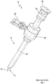
- the trocar system 10 is also generally referred to as a trocar.
- the trocar system 10 comprises a trocar pin 12 and a trocar sleeve 14 into which the trocar pin 12 can be inserted in order to insert the trocar system 10 into a body opening, for example in the abdominal cavity.
- the trocar system 10 has an elongated design, the trocar mandrel 12 and the trocar sleeve 14 having a common longitudinal axis.
- the trocar mandrel 12 has a shaft 16, at the distal end of which a tip 18 is formed.
- a handling section 20 is formed at the proximal end of the shaft 16 of the trocar mandrel 12.
- the trocar sleeve 14 comprises a hollow shaft 24, which can also be referred to as a tube. Furthermore, the trocar sleeve 14 comprises a handling head 26 which is arranged at a proximal end of the trocar sleeve 14 or at least adjacent to the proximal end. By way of example, the handling head 26 has a connection 28 which is provided with a valve and via which flushing liquids, gases or the like can be supplied and discharged in a defined manner.
- the illustrated trocar system 10 has a rigid trocar sleeve 14, in particular a trocar sleeve 14 with a rigid hollow shaft 24.
- Trocar systems are also known which comprise trocar sleeves which are designed to be flexible and pliable at least in sections. This is especially necessary for the passage of curved instruments.
- trocar sleeves are illustrated, the hollow shafts of which are designed to be flexible and deflectable.
- the trocar sleeves illustrated below are made of an elastomeric material with a defined maximum Shore hardness.
- the trocar sleeves are made in one piece and integrate various components without the need for a multi-piece structure.
- the exemplary embodiments illustrated in more detail below relate to various aspects of the design and manufacture of trocar systems. It goes without saying that individual features that are provided in one of the embodiments can also be transferred to other embodiments, to be precise detached from other features of the respective exemplary embodiment.
- a first embodiment of a trocar sleeve which is designated as a whole by 40, is illustrated in more detail. Similar to in Fig. 1 As shown, the trocar sleeve 40 can be combined with a trocar mandrel to form a trocar system.
- the trocar sleeve 40 comprises a hollow shaft 42 and a handling head 44.
- the hollow shaft 42 and the handling head 44 are designed integrally and manufactured in one piece. Together, the handling head 44 and the hollow shaft 42 define a longitudinal extension of the trocar sleeve 40, see also one in FIG Fig. 3 longitudinal axis indicated by 68.
- the hollow shaft 42 defines a longitudinally extending passage 46 which is used to receive a trocar or an instrument.
- the hollow shaft 42 further comprises a distal end 48 and a proximal end 50.
- the distal end 48 is the end which faces the interior of the patient when the trocar sleeve 40 is received on a tissue section, in particular on an abdominal wall, of the patient.
- the proximal end 50 faces an operator or surgeon and accordingly faces away from the interior of the patient.
- the handling head 44 is formed at the proximal end 50 of the hollow shaft 42.
- the hollow shaft 42 has, at least in sections, a smooth surface 52, which in particular is not a corrugated surface or a corrugated surface is designed. Regardless of this, according to at least some configurations, a threaded section 54 is formed on the hollow shaft 42, which includes for example at least one thread 56, which can also be referred to as a helix.
- the threaded section 54 is also preferably designed as an integral part of the trocar sleeve 40. In this context, the broken sectional view according to FIG Fig. 3 referenced. It can be seen that the hollow shaft 42, the handling head 44 and, if present, the threaded section 54 are designed in one piece.
- the pitch and the height of the thread 56 can be variable and, in particular, take into account specific operating conditions. This can in particular include a large pitch at a distal end of the thread 56. On the other hand, a significantly reduced pitch can be provided at a proximal end of the thread turn 56. Similarly, the thread 56 can initially have a very small height at its distal end, which gradually develops towards a maximum height, with a greater decrease in height (per circumferential section) being provided towards the proximal end of the thread 56.
- This design has the advantage that on the one hand the trocar sleeve 40 can easily penetrate tissue, since the distal end of the thread 56 is designed as an insertion aid, so to speak.
- the trocar sleeve 40 in one piece and from a flexible material, in particular an elastomeric material, in an archetype.
- a flexible material in particular an elastomeric material
- This allows a great deal of creative freedom and, in particular, the molding / shaping of additional components.
- An advantage can be seen in the fact that with the selected materials there is no need to reckon with a high probability of the formation of cavities and the like. Thus, nothing always has to be taken into account to provide a wall thickness that is as constant as possible.
- This also applies in particular to the threaded section 54. Accordingly, both the surface 54 on the Outside of the hollow shaft 42 as well as an inner contour 72 (cf. Fig. 3 ) be designed smooth on the inside of the hollow shaft 52.
- the handling head 44 can nonetheless have a rib structure in order, on the one hand, to ensure high stability and, on the other hand, to avoid material accumulations.
- the handling head 44 is enlarged radially in relation to the hollow shaft 42 and also provides an enlarged receiving opening. Furthermore, the handling head 44 is provided with essentially axially extending ribs 58 as well as with essentially circumferentially extending ribs 60.
- the axial ribs 58 and the circumferential ribs 60 form a cross structure.
- the ribs 58, 60 define or surround recesses or depressions 62 which contribute to the avoidance of material accumulations or to weight reduction and to the optimization of the weight distribution.
- the hollow shaft 42 comprises a cylindrical wall 70 which surrounds the longitudinal axis 68.
- the inner contour 72 is formed on the inside of the wall 70.
- the illustrated embodiment of the trocar sleeve 40 in the handling head 44 has a groove-shaped receptacle 74 which can serve, for example, to receive a seal.
- the handling head 44 opens into a proximal end surface 66, which, however, can be preceded by the receptacle 74.
- a distal inner diameter of the hollow shaft 42 is denoted by D di.
- a proximal inner diameter of the hollow shaft 42 is denoted by D pi.
- a thickness of the wall 70 at the distal end 48 is denoted by t d.
- a thickness of the wall 70 at the proximal end of the hollow shaft 42 is denoted by t p.
- configurations are also conceivable, compare in particular those in FIG Fig. 3 shown embodiment, wherein the wall thickness of the wall 70 increases from the distal end 48 to the proximal end 50 (t d ⁇ t p ). All of the above-mentioned embodiments can be combined with one another.
- the inner contour 72 is adapted to an outer contour of a trocar pin in such a way that the hollow shaft 72 is widened in the desired manner when the trocar pin is inserted into the trocar sleeve 40. It is therefore advantageous if at least the hollow shaft 42 or the trocar mandrel is designed to be conical, conical or spherical, at least in sections.
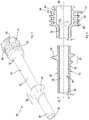
- FIG. 4, 5 and 6th Reference may be made to this, which illustrate a trocar system 76 incorporating a trocar sleeve 40 according to FIGS Figs. 2 and 3 and a trocar pin designated 80.
- the trocar mandrel 80 has a tip 82 at its distal end and a handle portion 84 at its proximal end facing away from the distal end.
- a shaft 86 extends between the tip 82 and the handling section 84.
- a circumferential contour or outer contour 88 is formed on the shaft 86 and comes to rest against the inner contour 72 of the hollow shaft 42 of the trocar sleeve 40.
- a proximal dimension or a proximal diameter of the outer contour 88 is described by D pe .
- a distal dimension or a distal diameter of the outer contour 88 is described by D de .
- 80 D pe D de applies to the trocar mandrel.
- the shaft 86 of the Trocar 80 is designed to be cylindrical, at least along essential sections of its longitudinal extension, and consequently has a constant cross section.
- D de applies.
- the shaft 86 of the trocar mandrel 80 can also be tapered conically or spherically, at least in sections, in the direction of its distal end.
- the tip 82 is also provided. Accordingly, it is conceivable that at least the inner contour 72 or the outer contour 88 are designed to be tapered in the direction of the distal end. However, it is also conceivable to design both the inner contour 72 and the outer contour 88 to be cylindrical with constant cross-sections. It should also be noted that the cross-sections of the inner contour 72 and / or the outer contour 88 do not necessarily have to be circular. Oval cross-sections or cross-sections deviating in any other way from a pure circular shape are also conceivable. In this respect, the terms D di , D pi , D de and D pe used here are not necessarily to be understood as diameter specifications.
- FIG. 11 shows a state of the trocar system 76 in which the trocar mandrel 80 has been inserted into the trocar sleeve 40 but not yet completely passed through the sleeve 40, compare an offset dimension O 1 in FIG Fig. 4 between the distal end 48 of the trocar sleeve 40 and the tip 82 of the trocar mandrel 80. Furthermore, FIG Fig. 4 an insertion direction is designated by 92.
- the trocar 80 is completely inserted into the trocar sleeve 40, so that the tip 82 protrudes beyond the distal end 48 of the hollow shaft 42, compare FIG Fig. 5 offset dimension marked with O 2. Furthermore, in Fig. 5 the handling section 84 of the trocar mandrel 80 comes to rest against the handling head 44 of the trocar sleeve 40. The handling section 84 makes contact with the proximal end surface 66 of the handling head 44.
- the trocar pin 80 expands the hollow shaft 42 of the trocar sleeve 40 when the trocar pin 80 is inserted into the trocar sleeve 40 or is completely inserted.
- a corresponding radial disengagement of the hollow shaft 42 is shown in FIG Fig. 5 illustrated by arrows labeled 94.
- the outer contour 88 of the trocar 80 has a certain "oversize” compared to the inner contour 72 of the hollow shaft 42, so that the "soft" Hollow shaft 42 is expanded. In this way, stresses are generated in the hollow shaft 42, in particular in the area of the inner contour 72 which is in direct contact with the outer contour 88. These tensions stabilize the actually soft, elastic trocar sleeve 40.
- the hollow shaft 42 sits under pretension on the trocar mandrel 80. In this way, when the trocar is set, compression or stretching of the hollow shaft 42 in the direction of its longitudinal extension is effectively reduced or virtually reduced completely prevented. The same applies to a twisting (twisting) of the hollow shaft 42 about its longitudinal axis.
- Fig. 6 if the "oversize" of the trocar 80 with respect to the inner contour 72 of the hollow shaft 42 is indicated in an overlapping area, compare the outer dimension (outer diameter D e ) of the trocar 80 and the inner dimension (inner diameter T i ) of the hollow shaft 42.
- a desired oversize can be defined, which leads to a defined preload in the hollow shaft 42.
- various configurations including cylindrical, conical and / or spherical configurations are conceivable in order to bring about a desired voltage characteristic. This can in particular relate to a relationship between the preload achieved in the case of the hollow shaft 72 and the current axial position of the trocar mandrel 80 in relation to the trocar sleeve 40.
- FIG. 14 illustrates a modified embodiment of a trocar sleeve, designated 140.
- the trocar sleeve 140 is basically the one based on FIG Figures 2 to 6 illustrated trocar sleeve 40 designed similarly.
- the trocar sleeve 140 is provided with a hollow shaft 42 and a handling head 44 in the manner already described above.
- a seal 100 is formed, which has a circumferential sealing contour or sealing lip 102.
- the hatching of the longitudinal section through the trocar sleeve 140 according to FIG Fig. 7 it can be seen that the seal 100 is designed as an integral part of the trocar sleeve 140. Since the trocar sleeve 140 is manufactured integrally from an elastomeric material, sealing arrangements can also be integrated and formed in one piece with the hollow shaft 42 and the handling head 44.
- the trocar sleeve 240 is also basically designed similar to the trocar sleeve 40 and is provided with a hollow shaft 42 and a handling head 44. Furthermore, a threaded section 54 is formed by way of example.
- Fig. 9 It can be seen that the thickness or thickness of the wall 70 of the hollow shaft 42 increases significantly from the distal end 48 to the proximal end 50, compare the dimensions t d and t p . In this way, a desired strength profile or preload profile can be brought about along the longitudinal axis of the hollow shaft 42, in particular when a trocar pin is inserted into the trocar sleeve 240.
- the handling head 44 is shown in FIGS. 8 and 9 compact design and not provided with stiffeners. Such a design is also conceivable.
- a receptacle contour or receptacle 74 for a seal is formed on the handling head 44, cf. Fig. 9 .
- the handling head 44 has a concave transition 106.
- rib-like elevations 108 are formed, see also on this Fig. 10 , which is explained in more detail below. That in the Figures 8 and 9
- the exemplary embodiment shown comprises two rib-like elevations 108 which are arranged offset from one another by 180 ° and which are raised in relation to the concave transition 106.
- the handling head 44 opens into a proximal end surface 110, which, however, the receptacle 74 can be positioned proximally in front of it.
- Fig. 10 illustrates an axial section through the basis of the Figures 8 and 9 illustrated trocar sleeve 240.
- a section is indicated by a line XX.
- the wall 70 of the hollow shaft 42 can be expanded.
- the wall 70 encloses a circular passage 46. It goes without saying that other profiles are also conceivable.
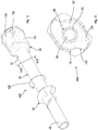
- Fig. 11 illustrates a further axial section through a trocar sleeve, which is designated by 340.
- a trocar pin 180 is received in the trocar sleeve 340.
- the illustrated configuration of the trocar sleeve 340 does not completely correspond to the configuration of the trocar sleeve 240 according to FIG Fig. 9 . Nevertheless, primarily for illustrative purposes in Fig. 9 a section line indicated by a line labeled XI-XI.
- Fig. 11 shows a view from the proximal end of the thread 56 of the thread section 54.
- a height of the thread 56 in relation to a surface 52 of the hollow shaft 42 is variable.
- the trocar sleeve 340 and the trocar mandrel 180 according to the configuration in FIG Fig. 11 further differ from the above-described embodiments by a rotation lock 114.
- the rotation lock 114 in the trocar pin 180 comprises at least one position locking element 116.
- the rotation lock 114 in the trocar sleeve 340 includes at least one position locking element 118.
- the position locking element 116 is in the longitudinal direction extensive elevation.
- the position securing element 118 is a recess which extends in the longitudinal direction and is adapted to the elevation.
- the anti-rotation device 114 comprises two pairs of position-securing elements 116, 118 offset by 180 °.
- the preload in the hollow shaft 42 increases, especially in the area of the position securing elements 116, 118 when the position securing elements 116, 118 want to disengage.
- the greater the actual deforming moment the greater the stability of the hollow shaft 42.
- the anti-rotation device 114 can also include other designs of position-securing elements 116, 118.
- profiles of the inner contour 72 and the outer contour 88 can be oval or non-circular in some other way.
- FIG. 4 Another embodiment of a trocar sleeve, designated 440, is illustrated.
- the trocar sleeve 440 corresponds in principle to the configuration based on the Figures 2 to 6 trocar sleeve 40 illustrated.
- FIG. 4 illustrates an axial section through the trocar sleeve 440 which, for reasons of illustration, is shown in the perspective illustration of FIG Fig. 12 is represented by a line XIII-XIII.
- the trocar sleeve 440 primarily differs from the configurations according to FIGS Figures 2 to 6 by the design of the handling head 44.
- the handling head 44 of the trocar sleeve 440 is compact and has no ribs or depressions. In this respect, the handling head 44 does have material accumulations, but this is not particularly disadvantageous with the selected materials or manufacturing processes.
- the frontal view of Fig. 13 It can be seen that the handling head 44 comprises a thickening 122, with elevations 124 extending radially outward from the thickening 122. As an example, two elevations 124 offset by 180 ° are provided.
- the elevations 124 each include a driving flank 126, via which a force can be introduced, for example in order to rotate the trocar sleeve 440, compare one in FIG Fig. 12 arrow labeled 128 to illustrate the direction of rotation.
- the trocar sleeve 440 ideally a trocar system comprising the trocar sleeve 440 and a trocar pin received therein, can be actuated in order, for example, to screw in the threaded section 54. In this way, the introduction of the trocar system is simplified.
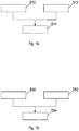
- the method comprises a step S10, which includes the provision of a mold which is designed to produce a trocar sleeve with a flexible hollow shaft and a handling head.
- the mold usually comprises at least one cavity, which to a certain extent represents a negative of the desired trocar sleeve.
- an elastomer material is provided, preferably a material which has a defined Shore hardness in the processed state.
- Steps S10 and S12 are followed by a further step S14, which relates to the primary forming of the trocar sleeve.
- Step S14 includes filling the mold with a suitable starting material.
- the primary shaping further includes forming the hollow shaft and the handling head in one piece.
- an inner contour is selected on the hollow shaft which is adapted to an outer contour of a trocar mandrel in such a way that the trocar sleeve and the trocar mandrel can be coupled to one another while generating a defined pretension in order to guide the trocar sleeve in a defined manner.
- a method of providing a trocar system is illustrated in block diagram form.
- the method comprises a step S50, which comprises the production of a trocar sleeve, in particular in accordance with the method on the basis of FIG Fig. 14 illustrated manufacturing processes.
- the method comprises a further step S52, which comprises the provision of a trocar mandrel which is adapted to the trocar sleeve.
- the trocar pin has an outer contour which is adapted to an inner contour of the hollow shaft of the trocar sleeve. This includes, in particular, designs in which the outer contour of the trocar pin is deliberately chosen to be somewhat larger than the corresponding inner contour of the hollow shaft.
- a step S54 follows, which relates to an introduction of the trocar mandrel into the trocar sleeve, the trocar sleeve being expanded at least in sections.
- a defined pre-tension is generated in the hollow shaft of the trocar sleeve. This can be used in particular for mechanical stabilization of the trocar sleeve in connection with the trocar mandrel.
Landscapes
- Health & Medical Sciences (AREA)
- Life Sciences & Earth Sciences (AREA)
- Surgery (AREA)
- Heart & Thoracic Surgery (AREA)
- Engineering & Computer Science (AREA)
- Biomedical Technology (AREA)
- Nuclear Medicine, Radiotherapy & Molecular Imaging (AREA)
- Medical Informatics (AREA)
- Molecular Biology (AREA)
- Animal Behavior & Ethology (AREA)
- General Health & Medical Sciences (AREA)
- Public Health (AREA)
- Veterinary Medicine (AREA)
- Pathology (AREA)
- Surgical Instruments (AREA)
Description
- Die Erfindung betrifft ein Trokarsystem, mit einer Trokarhülse und einem Trokardorn, wobei die Trokarhülse mit einem flexiblen Hohlschaft, der ein distales Ende und ein proximales Ende aufweist, und mit einem Handhabungskopf versehen ist, der am proximalen Ende des Hohlschaftes ausgebildet ist, und wobei die Trokarhülse aus einem elastomeren Werkstoff hergestellt ist. Schließlich betrifft die Offenbarung ferner ein Verfahren zur Bereitstellung eines Trokarsystems, umfassend die Herstellung einer Trokarhülse.
- Aus der
DE 42 34 990 A1 ist eine flexible Trokarhülse bekannt, die ein Rohr und einen Aufsatz umfasst, wobei ein distaler Bereich des Rohres durch eine Trokareinstichstelle ins Körperinnere einführbar ist, wobei der Aufsatz an einem proximalen Ende des Rohres angebracht ist, wobei der Aufsatz an seiner proximalen Stirnseite eine Öffnung aufweist, der eine Dichtung zugeordnet ist, und wobei das Rohr aus einem flexiblen Material besteht. Zur Kopplung des Rohres und des Aufsatzes ist ein Zwischenrohr vorgesehen. - Aus der
DE 43 12 147 A1 ist ein Trokar bekannt, mit einem Obturator, der eine Bohrspitze zur Durchbohrung von Körpergewebe aufweist, und einer Kanüle zum Ausbilden einer Passage in dem von der Bohrspitze durchbohrten Gewebe, so dass ein Endoskop oder ein chirurgisches Werkzeug in eine Körperhöhle einführbar ist, wobei die Kanüle aus einer flexiblen Röhre oder einer Schraubenfederwicklungs-Röhre geformt ist. - Aus der
DE 101 56 312 A1 ist ein Schaft für einen chirurgisch hergestellten Zugang bekannt, der an seinem distalen Ende an seiner Außenfläche einen Gewindesteg aufweist, welcher sich in Umfangsrichtung des Schaftes nur über einen Teilbereich des Umfanges erstreckt. - Aus der
EP 0 535 974 A1 ist ein Trokarsystem mit einem flexiblen Trokarrohr bekannt. - Trokarhülsen dienen allgemein dazu, bei einem minimalinvasiven Eingriff einen Zugang zu einer Körperhöhle bereitzustellen. Trokarsysteme umfassend Trokarhülsen sowie Trokardorne werden beispielsweise bei der Laparoskopie verwendet, um einen Zugang zur Bauchhöhle zu schaffen. Zu diesem Zweck umfasst die Trokarhülse einen Hohlschaft. Beim Setzen der Trokarhülse wird das Trokarsystem über eine Inzision in der Bauchdecke oder allgemein in einem Gewebe angesetzt und durch diese hindurchgeschoben. Danach ragt das distale Ende des Schaftes in die Bauchhöhle hinein, das proximale Ende steht von der Oberseite der Bauchdecke oder des Gewebes ab. Aus Sicht eines Bedieners oder Operateurs ist das distale Ende das dem Operateur abgewandte Ende. Das proximale Ende ist das dem Operateur zugewandte Ende.
- Die Kombination aus Trokarhülse und Trokardorn wird allgemein als Trokar bzw. Trokarsystem bezeichnet. Ausführungsformen von Trokarsystemen umfassen eine Trokarhülse sowie einen Trokardorn, der in den Hohlschaft der Trokarhülse einschiebbar ist. Üblicherweise weist der Trokardorn an seinem distalen Ende eine Spitze auf. Die Spitze reicht über das distale Ende der Trokarhülse hinaus, wenn der Trokardorn vollständig in diese eingeschoben ist. Gemeinsam können die Trokarhülse und der Trokardorn durch die Bauchdecke oder ein anderes Gewebe hindurchgeschoben werden, um eine Zugangsöffnung zu schaffen. Nach dem Setzen der Trokarhülse wird der Trokardorn abgezogen bzw. ausgezogen. Somit können durch die verbliebene Ausnehmung im Hohlschaft Instrumente in die Körperhöhle oder Körperöffnung eingeführt werden.
- Trokarhülsen können ferner ein proximales Kopfteil aufweisen, das auch im gesetzten Zustand der Trokarhülse üblicherweise nicht in das Körperinnere eindringt. Das Kopfteil kann auch als Handhabungskopf bezeichnet werden. Beispielhaft weist das Kopfteil Anschlüsse auf, um ein Insufflationsgas, Spülflüssigkeiten oder dergleichen durch die Trokarhülse hindurchzuführen. Darüber hinaus kann am Kopfteil selbst oder zumindest dem Kopfteil benachbart bei der Trokarhülse eine Dichtungsanordnung vorgesehen sein, um einen Verschluss bzw. eine Abdichtung des Trokarsystems zu ermöglichen.
- Trokarhülsen selbst, insbesondere deren Hohlschäfte, können grundsätzlich aus einem hinreichend steifen und starren Werkstoff gefertigt sein, insbesondere aus Metallwerkstoffen. Es sind jedoch auch sogenannte flexible Trokarhülsen bzw. Trokarhülsen mit flexiblen Hohlschäften bekannt, die verformbar bzw. verbiegbar sind. Dies ist beispielsweise bei der Durchführung gebogener Instrumente bzw. auslenkbarer Instrumentenschäfte von Vorteil.
- Derartige flexible Hohlschäfte können beispielhaft aus thermoplastischen oder duroplastischen Werkstoffen hergestellt werden. Üblicherweise ist eine derartige Trokarhülse als gebaute, mehrteilige Trokarhülse ausgeführt, wobei zumindest das Kopfteil und der Hohlschaft separate Komponenten sind, die miteinander gefügt werden.
- Weitere beispielhafte Ausführungsformen von Trokarhülsen umfassen einen Gewindeabschnitt, der ausgehend vom proximalen Ende der Trokarhülse in Richtung auf das distale Ende versetzt ist. Mit anderen Worten kann ein derartiger Gewindeabschnitt, der etwa helixartig gestaltet ist, entlang der Längserstreckung des Hohlschaftes vorgesehen sein und sich von diesem ausgehend spiralförmig nach außen erheben. Eine Trokarhülse mit einer derartigen Gestaltung ist beispielsweise in der nachveröffentlichten
EP 3 009 088 A1 beschrieben. - Beispielhaft ist die Helix an einem Längsabschnitt des Hohlschaftes ausgebildet, der vom Kopfteil derart beabstandet ist, dass die eingeführte Trokarhülse außerhalb des Körpers durch das Kopfteil sowie innerhalb des Körpers durch die Helix gestützt wird, wobei im gesetzten Zustand zwischen der Helix und dem Kopfteil eine Gewebeschicht (etwa die Bauchdecke) angeordnet ist. Somit kann die Helix eine innere Anlagefläche bereitstellen. Das Kopfteil kann eine äußere Anlagefläche bereitstellen. Es sind auch Ausgestaltungen vorstellbar, bei denen zwischen der Helix und dem Kopfteil ein weiterer Gewindeabschnitt (oder insgesamt ein durchgängiges Gewinde) ausgebildet ist, auf dem eine Art Kontermutter zur Fixierung der Trokarhülse zwischen der Helix und der Kontermutter sitzt.
- In diesem Zusammenhang wird ferner auf die
DE 101 56312 A1 verwiesen, die einen Schaft für einen chirurgisch hergestellten Zugang offenbart, wobei der Schaft an seinem distalen Ende an seiner Außenfläche einen Gewindesteg aufweist. - Bekannte Trokarhülsen mit zumindest hinreichend flexibel gestalteten Hohlschäften weisen üblicherweise einen mehrstückigen Aufbau auf, insbesondere betreffend die Verbindung zwischen dem Hohlschaft und dem Kopfteil. Es besteht häufig ein Widerspruch zwischen der gewünschten hohen Flexibilität und der gleichzeitig erforderlichen Stabilität des Hohlschaftes.
- Ferner sind Trokarhülsen mit wellrohrartig gestalteten Hohlschäften bekannt. Diese Gestaltung (korrugierte Rohre) erhöht die Flexibilität des Hohlschaftes. Ähnliches kann etwa mit einem gewindeartigen Spiralprofil bewirkt werden, das außen am Hohlschaft eine Erhebung und innen am Hohlschaft eine entsprechende Vertiefung aufweist, wobei die Wandstärke des Hohlschaftes im Wesentlichen konstant bleiben kann. Mit anderen Worten erstreckt sich die Außenwand des Hohlschaftes mäanderförmig. Beide Maßnahmen haben den Nachteil, dass die Relativbewegung zwischen dem Instrument und dem Hohlschaft erschwert wird, da die Innenkontur des Hohlschaftes nicht glatt ist. Darüber hinaus neigen derartig gestaltete Hohlschäfte zum Knicken bzw. zur Faltenbildung.
- Vor diesem Hintergrund liegt der Erfindung die Aufgabe zugrunde, ein Trokarsystem mit einer Trokarhülse anzugeben, die einerseits hochflexibel gestaltet ist und sich somit für gebogene Instrumente eignet. Ferner soll die Trokarhülse hinreichend fest und steif gestaltet sein, um das definierte Setzen des Trokars bzw. das Einführen der Trokarhülse zu vereinfachen. Darüber hinaus soll die Trokarhülse möglichst wirtschaftlich herstellbar sein. Insbesondere soll nach Möglichkeit auf zusätzliche Montageschritte bzw. Fertigungsschritte verzichtet werden können. Die Trokarhülse soll ferner nach Möglichkeit Zusatzfunktionen bereitstellen. Darüber hinaus soll die Trokarhülse eine hohe Biokompatibilität aufweisen. Strukturelle Schnittstellen zwischen beteiligten Komponenten sollen weitgehend vermieden werden. Schließlich soll im Rahmen der vorliegenden Offenbarung ein korrespondierendes Verfahren zur Bereitstellung eines Trokarsystems umfassend eine Trokarhülse sowie einen Trokardorn angegeben werden.
- Das Trokarsystem betreffend wird die Aufgabe dadurch gelöst, dass der Hohlschaft eine Innenkontur aufweist, die derart an eine Außenkontur des Trokardorns angepasst ist, dass die Trokarhülse und der Trokardorn unter Erzeugung einer definierten Vorspannung miteinander koppelbar sind, um die Trokarhülse zu stabilisieren, dass der Trokardorn unter Erzeugung der definierten Vorspannung in die Trokarhülse einführbar ist, und dass zumindest der Hohlschaft und der Handhabungskopf einstückig gestaltet sind.
- Erfindungsgemäß ist nämlich die Trokarhülse derart ausgeführt, dass sich im Zusammenspiel mit dem Trokardorn eine definierte, zumindest partielle Aufweitung (radiale Dehnung nach Außen) ergibt, die eine Vorspannung bewirkt. Die Vorspannung versteift die Trokarhülse bzw. erhöht die Festigkeit der Trokarhülse, insbesondere beim Hohlschaft. Auf diese Weise kann die Trokarhülse bzgl. ihrer Längsachse druckbelastet, zugbelastet bzw. torsionsbelastet werden, ohne dass es zu übermäßigen Verformungen, Stauchungen und dergleichen kommt. Nach dem Setzen der Trokarhülse kann der Trokardorn entfernt werden. Auf diese Weise wird die Aufweitung rückgängig gemacht und die Vorspannung abgebaut. Somit steht dann eine hohe Flexibilität/Biegsamkeit insbesondere des Hohlschaftes zur Verfügung.
- Auf diese Weise kann die Trokarhülse einerseits hochflexibel gestaltet sein. Andererseits ist eine deutlich erhöhte Festigkeit gegeben, wenn der Trokardorn in definierter Weise in den Hohlschaft eingebracht ist. Die Trokarhülse kann definiert geführt werden.
- Mit anderen Worten ist die Innenkontur des Hohlschaftes bewusst etwas zu klein für eine gegebene Außenkontur des Trokardorns gestaltet. Auf diese Weise wird die Innenkontur und somit der gesamte Hohlschaft auf das durch die Außenkontur des Trokardorns vorgegebenen Nennmaß aufgeweitet. Mit anderen Worten weist die Innenkontur im unbelasteten Zustand eine definierte Überdeckung in Bezug auf die Außenkontur des Hohlschaftes auf.
- Gemäß dem obigen Aspekt kann die Trokarhülse ohne separate Stützelemente ausgeführt sein und allein durch das Einbringen des Trokardorns eine hohe Stabilität aufweisen. Dies ist eine Voraussetzung für die möglichst integrale Gestaltung der Trokarhülse. Die Trokarhülse weist eine hohe Eigenstabilität auf, wenn der flexible Hohlschaft durch den Trokardorn zumindest abschnittsweise aufgeweitet ist.
- Die Innenkontur des Hohlschaftes kann beispielsweise als Durchgangsloch oder Durchgangskanal ausgeführt sein. Die Innenkontur kann grundsätzlich einen runden Querschnitt umfassen. Andere Querschnittsformen sind vorstellbar. Der Trokardorn weist üblicherweise eine Außenkontur auf, die an die Innenkontur des Hohlschaftes angepasst ist. Demgemäß kann auch der Trokardorn eine Außenkontur mit runden oder kreisförmigen Querschnitten umfassen. Es ist jedoch auch vorstellbar, den Hohlschaft und den Trokardorn derart zu gestalten, dass sich bei der Innenkontur und bei der Außenkontur nicht korrespondierende bzw. nicht kongruente Querschnitte ergeben. Beispielhaft kann der Trokardorn zumindest abschnittsweise einen ovalen Querschnitt aufweisen, wogegen die Innenkontur des Hohlschaftes einen kreisförmigen Querschnitt aufweist oder zumindest einen ovalen Querschnitt mit einem Seitenverhältnis, das vom Seitenverhältnis des Querschnitts der Außenkontur abweicht.
- Es versteht sich, dass der Hohlschaft nicht vollständig entlang seiner Längserstreckung durch den Trokardorn aufgeweitet werden muss. Vielmehr ist es vorstellbar, dass der Hohlschaft abschnittsweise entlang seiner Längserstreckung und/oder abschnittsweise entlang seiner Umfangserstreckung durch den Trokardorn aufgeweitet wird.
- Der flexible Hohlschaft ist zur Aufnahme eines Trokardorns und zur Durchführung von Instrumenten ausgebildet. Durch ein definiertes Einführen des Trokardorns in den Hohlschaft kann die Überdeckung bzw. Aufweitung beeinflusst werden. Beispielsweise kann die Aufweitung der Innenkontur des Hohlschaftes von einer axialen Relativlage zwischen dem Trokardorn und dem Hohlschaft abhängig sein. Dies gilt insbesondere dann, wenn zumindest die Innenkontur oder die Außenkontur zumindest abschnittsweise konisch oder sphärisch gestaltet sind.
- In einer Ausgestaltung der Trokarhülse ist der Hohlschaft in einer definierten axialen Relativlage zwischen den Trokarhülse und dem Trokardorn zumindest abschnittsweise aufgeweitet. Dies betrifft einen Zustand, in dem der Trokardorn in die Trokarhülse eingefügt ist. Auf diese Weise kann ein Verbund geschaffen werden, um die Trokarhülse durch die Bauchdecke oder das Gewebe zumindest abschnittsweise in das Körperinnere einzuführen.
- Bei dem elastomeren Werkstoff handelt es sich insbesondere um einen Werkstoff, der eine Shore Härte von höchstens 90 Shore A aufweist. Bei Elastomeren handelt es sich allgemein um Werkstoffe, die hinreichend formfest gestaltet sind aber gleichwohl elastisch verformbar sind. Üblicherweise werden Elastomere in einem Temperaturbereich eingesetzt, der über der Glasübergangstemperatur bzw. über dem Glasübergangspunkt liegt. Elastomere Werkstoffe zeigen allgemein ein gummielastisches Verhalten.
- Beispielhaft kann zumindest der Hohlschaft, insbesondere dessen Innenkontur, oder der Trokardorn, insbesondere dessen Außenkontur, zumindest abschnittsweise konisch gestaltet sein. Mit anderen Worten kann sich zumindest der Querschnitt der Innenkontur oder der Querschnitt der Außenkontur vom proximalen Ende in Richtung auf das distale Ende hin verjüngen. Demgemäß kann über einen gewählten axialen Versatz zwischen dem Trokardorn und der Trokarhülse der Grad der Überdeckung bzw. der Aufweitung bestimmt werden. Somit kann auch die Höhe der Vorspannung im Hohlschaft der Trokarhülse beeinflusst werden. Je höher die Vorspannung des Hohlschaftes, desto höher ist die Eigenstabilität beim Einführen in das Körperinnere.
- Es ist vorstellbar, eine einzige definierte axiale Relativlage vorzusehen, welche im Wesentlichen zu genau einer definierten Überdeckung und somit zu einer definierten Vorspannung führt. Dies kann etwa durch geeignete Anschläge bewerkstelligt werden, um das axiale Eindringen bzw. Durchdringen des Trokardorns in Bezug auf die Trokarhülse zu begrenzen. Umgekehrt ist es vorstellbar, bewusst keinen Anschlag vorzusehen, um eine Variation der axialen Relativlage (des axialen Versatzes) und somit der Vorspannung zu erlauben.
- Gemäß einer weiteren Ausgestaltung beträgt die Shore Härte des elastomeren Werkstoffs, bestimmt gemäß DIN ISO 7619-1, maximal 90 Shore A, vorzugsweise maximal 70 Shore A. Ein minimaler Wert für die Härte kann etwa 50 Shore A betragen. Denkbare Bereiche für die Shore Härte des elastomeren Werkstoffs liegen zumindest gemäß einigen Ausführungsbeispielen zwischen 50 und 90 Shore A, vorzugsweise zwischen 50 und 70 Shore A. Je niedriger der Wert der Shore Härte, desto schwächer ist die Vernetzung des Werkstoffs und desto weicher ist das Material. Gemäß einer beispielshaften Ausführungsform ist eine Shore Härte von etwa 70 Shore A (bzw. von 70 Shore A) vorgesehen. Es versteht sich, dass übliche Toleranzen, mit denen bei der Gestaltung und Verarbeitung elastomerer Werkstoffe zu rechnen ist, hiervon umfasst sind.
- Zumindest der Hohlschaft und der Handhabungskopf der Trokarhülse sind einstückig gestaltet, wobei die Trokarhülse vorzugsweise integral gestaltet und urformend hergestellt ist. Auf diese Weise kann der Herstellungsaufwand und insbesondere der Montageaufwand deutlich reduziert werden. Vorzugsweise ist die Trokarhülse vollständig oder nahezu vollständig integral gefertigt. Insbesondere der Hohlschaft und der Handhabungskopf sind vorzugsweise einstückig geformt und gemeinsam hergestellt. Es versteht sich, dass insbesondere der Handhabungskopf mit weiteren Elementen bestückt werden kann, etwa mit Dichtungsanordnungen, Anschlüssen, Ventilen und dergleichen.
- Gleichwohl führt die gemeinsame, integrale Gestaltung des Hohlschaftes und des Handhabungskopfes aus dem elastomeren Werkstoff zu einer fertigungstechnischen Optimierung. Es gibt keine strukturelle Schnittstelle und keine Schnittstelle zwischen verschiedenen Werkstoffen beim Übergang zwischen dem Hohlschaft und dem Handhabungskopf. Dies ist hygienisch vorteilhaft.
- Gemäß einer weiteren Ausgestaltung der Trokarhülse ist der elastomere Werkstoff aus der Gruppe ausgewählt, die aus Folgenden besteht: Silikone, Silikonkautschuk, thermoplastische Elastomere (TPE), Kautschuk sowie diese enthaltende Compounds. Kautschuk umfasst synthetischen Kautschuk und Naturkautschuk. Bei dem Elastomer handelt es sich zum Beispiel um Ethylen-Propylen-Dien-Kautschuk (EPDM).
- Gemäß einer weiteren Ausgestaltung der Trokarhülse ist der Hohlschaft zumindest abschnittsweise rohrartig oder zylinderartig gestaltet und weist zumindest abschnittsweise eine glatte erhebungsfreie Außenfläche auf. Vorzugsweise ist die Innenkontur zumindest abschnittsweise mit einer reibungsmindernden Beschichtung versehen. Die reibungsmindernde Beschichtung kann beispielsweise aus Polytetrafluorethylen (PTFE) bestehen oder dieses umfassen. Andere Stoffe zur Reibungsminimierung bzw. Reibungsoptimierung sind denkbar.
- Zur Minimierung der Reibung zwischen dem Hohlschaft und einzuführenden Instrumenten bzw. dem Trokardorn kann eine Fluorierung zumindest eines Kontaktbereichs der Innenkontur des Hohlschaftes vorgesehen sein.
- Die Innenkontur des Hohlschaftes ist vorzugsweise zumindest in dem Bereich, in dem dieser durch den Trokardorn kontaktiert wird, glatt ausgeführt. Mit anderen Worten gibt es kein sich axial erstreckendes Wellprofil mit umlaufenden Abschnitten bzw. keine schraubenförmigen Furchen bei der Innenkontur. Dies vereinfacht die Handhabung und Durchführung und Instrumenten durch den Hohlschaft. Insbesondere das Anhaften bzw. Klemmen von Instrumenten wird deutlich erschwert.
- Vorzugsweise ist auch die Außenkontur oder Außenfläche des Hohlschaftes zumindest abschnittsweise glatt und ohne Erhebungen ausgeführt. Gleichwohl versteht sich, dass zumindest ein Gewindeabschnitt an der Außenkontur des Hohlschaftes ausgebildet sein kann. Jedoch ist der Hohlschaft der Trokarhülse insbesondere zur Erhöhung der Biegsamkeit bzw. Flexibilität nicht mit einer wellrohrartigen Gestaltung versehen. Mit anderen Worten ist der Hohlschaft vorzugsweise nicht-korrugiert ausgeführt.
- Gemäß einer weiteren Ausgestaltung der Trokarhülse weist der Hohlschaft zumindest abschnittsweise eine sich von einem distalen Ende hin zu einem proximalen Ende erhöhende Wandstärke auf. Insbesondere kann es sich um eine stetige oder quasi-stetige Erhöhung der Wandstärke handeln. Diese Maßnahme hat den Vorteil, dass der Hohlschaft selbst in einem Übergangsbereich mit dem Handhabungskopf hinreichend fest gestaltet ist. Das distale Ende des Hohlschaftes, das nur relativ geringe Wandstärken aufweist, kann demgegenüber durch den einzuführenden Trokardorn einfach aufgeweitet werden, wobei eine Vorspannung erzeugt wird, die die Festigkeit der Trokarhülse erhöht.
- Gemäß einer weiteren Ausgestaltung der Trokarhülse ist die Innenkontur des Hohlschaftes zumindest abschnittsweise konisch oder sphärisch mit einem von einem distalen Ende hin zu einem proximalen Ende größer werdenden Innendurchmesser gestaltet. Auch auf diese Weise kann das distale Ende des Hohlschaftes besonders einfach aufgeweitet werden, wodurch sich die Stabilität des Hohlschaftes im Verbund mit dem Trokardorn erhöht. Ferner kann der Hohlschaft insgesamt in Richtung auf das distale Ende verjüngt sein, was das Eindringen des Trokarsystems weiter vereinfacht. Gemäß einer Weiterbildung der obigen Ausgestaltung ist die Innenkontur des Hohlschaftes an eine zumindest abschnittweise konische oder sphärische Gestaltung der Außenkontur des Trokardorns angepasst, um die Trokarhülse beim Einführen des Trokardorns definiert vorzuspannen. Auch dies kann zur gewünschten Festigkeitssteigerung bzw. zur Erhöhung der Stabilität der Trokarhülse beitragen.
- Gemäß einer weiteren Ausgestaltung der Trokarhülse ist am Hohlschaft ein Gewindeabschnitt ausgebildet, wobei der Hohlschaft, der Gewindeabschnitt und der Handhabungskopf einstückig gestaltet sind. Vorzugsweise ist der Gewindeabschnitt als Erhebung an einem Außenumfang des Hohlschaftes ausgeformt. Gemeinsam können der Hohlschaft, der Gewindeabschnitt und der Handhabungskopf aus demselben elastomeren Werkstoff gefertigt sein.
- Es sind Ausgestaltungen vorstellbar, bei denen ein erster und ein zweiter Gewindeabschnitt am Hohlschaft ausgebildet ist, die axial voneinander versetzt sind. Der zweite Gewindeabschnitt kann genutzt werden, um eine Kontermutter aufzunehmen, die zwischen dem Handhabungskopf und dem ersten Gewindeabschnitt am Hohlschaft aufnehmbar ist. In diesem Zusammenhang wird erneut auf die nachveröffentlichte
EP 3 009 088 A1 verwiesen. - Vorteilhaft ist ferner, dass ein Fertigungsverfahren gewählt werden kann, das auch die Entformung/Ausformung zumindest teilweise hinterschnittiger Gestaltungen erlaubt. Insofern ist eine große gestalterische Freiheit gegeben.
- Der Gewindeabschnitt kann zumindest einen Gewindegang umfassen, dessen Höhe und Steigung variabel gestaltbar ist. Ferner kann etwa die Neigung von Flanken des Gewindeganges angewählte Einsatzbedingungen angepasst werden. Insgesamt kann ein im Wesentlichen frei definierbares Gewinde erzeugt werden, das einerseits ein leichtes Eindringen erlaubt, etwa durch eine hohe Steigung sowie eine geringe Höhe am distalen Auslauf des Gewindes. Ferner kann das Gewinde an seinem proximalen Auslauf etwa eine deutlich verringerte Steigung und eine größere Höhe als am distalen Auslauf aufweisen. Dies erhöht die Haltewirkung, insbesondere gegen versehentliches Herausziehen oder Herausreißen des Hohlschaftes aus dem Gewebe.
- Gemäß einer weiteren Ausgestaltung der Trokarhülse ist die Innenkontur des Hohlschaftes zumindest abschnittsweise nicht-rotationsymmetrisch ausgeführt. Insbesondere kann die Innenkontur einen unrunden Querschnitt senkrecht zur Längsrichtung bzw. einer damit korrespondierenden Längsachse des Hohlschaftes aufweisen.
- Auf diese Weise kann zwischen dem Hohlschaft der Trokarhülse und dem Trokardorn eine formschlüssige Drehmitnahmesicherung bewirkt werden. Demgemäß ist es von Vorteil, wenn auch der Trokardorn eine korrespondierende nichtrotationssymmetrische Gestaltung aufweist.
- Beispielhaft weist der Trokardorn zumindest abschnittsweise entlang seiner Längserstreckung zumindest eine wulstartige Erhebung auf, die an eine wulstartige Vertiefung des Hohlschaftes angepasst ist, die sich auch in der Längsrichtung erstreckt. Demgemäß kann eine Relativverdrehung zwischen dem Hohlschaft und dem Trokardorn unterbunden bzw. zumindest reduziert werden.
- In diesem Zusammenhang ist anzumerken, dass es gemäß zumindest einigen Ausgestaltungen nicht unbedingt darum geht, die Relativverdrehung zwischen dem Trokardorn und dem Hohlschaft vollständig zu unterbinden. Beispielhaft ist vorstellbar, dass der Hohlschaft bei einer Verdrehung des Trokardorns um dessen Längsachse zumindest abschnittsweise tordiert wird. Dies kann etwa dann der Fall sein, wenn zumindest abschnittsweise eine Drehmitnahme des Hohlschaftes durch den Trokardorn erfolgt, etwa aufgrund von Reibung zwischen der Innenkontur und der Außenkontur. Auch die Torsion oder Verdrillung des Hohlschaftes kann in gewünschter Weise eine Vorspannung beim Hohlschaft bewirken, die sich in einer erhöhten Stabilität niederschlägt.
- Beispielhaft ist es vorstellbar, die Innenkontur des Hohlschaftes und die Außenkontur des Trokardorns mit einem ovalen Querschnitt oder einem ähnlichen nichtzylindrischen Querschnitt zu versehen. Auf diese Weise kann einerseits eine übermäßige Relativverdrehung zwischen dem Trokardorn und dem Hohlschaft vermieden werden. Jedoch kann eben zumindest in Grenzen eine Relativbewegung mit einer teilweisen Verdrillung des Hohlschaftes bewirkt werden, um die Festigkeit des Hohlschaftes zu steigern.
- Gemäß einer weiteren Ausgestaltung der Trokarhülse ist am proximalen Ende des Hohlschaftes, insbesondere beim Handhabungskopf, eine Dichtungskontur oder eine Dichtungsaufnahmekontur ausgebildet. Mit anderen Worten sind Ausgestaltungen vorstellbar, bei denen auch eine Elastomerdichtung als integraler Bestandteil der Trokarhülse vorgesehen ist. Vorzugsweise ist die Dichtungskontur am Handhabungskopf aufgenommen. In alternativer Ausgestaltung ist am Handhabungskopf zumindest eine Dichtungsaufnahmekontur, etwa in Form einer umlaufenden Nut, zur Aufnahme einer separaten Dichtung vorgesehen.
- Ein weiterer offenbarungsgemäßer Aspekt betrifft ein Trokarsystem, das eine Trokarhülse gemäß einem der hier beschriebenen Ausführungsbeispiele sowie einen Trokardorn umfasst, wobei der Trokardorn unter Erzeugung einer definierten Vorspannung in die Trokarhülse einführbar ist. Der Trokardorn wird in den Hohlschaft der Trokarhülse eingeführt und kann diesen zumindest abschnittsweise aufweiten. Auf diese Weise wird der Hohlschaft und somit die Trokarhülse stabilisiert. Vorzugsweise ist die erzielbare Vorspannung von einer axialen Relativlage zwischen dem Trokardorn und dem Hohlschaft abhängig.
- Üblicherweise umfasst der Trokardorn an seinem distalen Ende eine Spitze. An die Spitze schließt sich ein Schaft an. Vorzugsweise ist der Schaft des Trokardorns zumindest abschnittsweise konisch oder sphärisch gestaltet. Insbesondere kann sich eine kegelartige Kontur ergeben. Auf diese Weise kann der Hohlschaft umso mehr aufgeweitet werden, je weiter der Trokardorn in den Hohlschaft eingeführt wird.
- Die Aufgabe der Erfindung wird ferner durch ein Verfahren zur Bereitstellung eines Trokarsystems gelöst, das die folgenden Schritte umfasst:
- Herstellung einer Trokarhülse, vorzugsweise einer Trokarhülse nach einem der vorstehend genannten Aspekte, wobei das Verfahren die folgenden Schritte aufweist:
- Bereitstellung einer Form, die zur Erzeugung einer Trokarhülse mit einem flexiblen Hohlschaft und einem Handhabungskopf ausgebildet ist,
- Bereitstellung eines elastomeren Werkstoffs, vorzugsweise eines Werkstoffs der im verarbeiteten Zustand einer Shore Härte, bestimmt gemäß DIN ISO 7619-1, von maximal 90 Shore A, vorzugsweise maximal 70 Shore A, weiter bevorzugt maximal 50 Shore A aufweist, und
- Urformen der Trokarhülse, umfassend Befüllen der Form, dabei einstückiges Formen des Hohlschaftes und des Handhabungskopfes, wobei am Hohlschaft eine Innenkontur ausgebildet wird, die derart an eine Außenkontur eines Trokardorns angepasst ist, dass die Trokarhülse und der Trokardorn unter Erzeugung einer definierten Vorspannung miteinander koppelbar sind, um die Trokarhülse zu stabilisieren,
- Bereitstellung eines Trokardorns, der an die Trokarhülse angepasst ist, und
- Einführen des Trokardorns in die Trokarhülse, dabei zumindest abschnittsweises Aufweiten der Trokarhülse, umfassend Erzeugung einer Vorspannung im Hohlschaft der Trokarhülse, zur mechanischen Stabilisierung der Trokarhülse.
- Es versteht sich, dass die vorstehend genannten und die nachstehend noch zu erläuternden Merkmale der Erfindung nicht nur in der jeweils angegebenen Kombination, sondern auch in anderen Kombinationen oder in Alleinstellung verwendbar sind, ohne den Rahmen der vorliegenden Erfindung zu verlassen.
- Weitere Merkmale und Vorteile der Erfindung ergeben sich aus der nachfolgenden Beschreibung mehrerer bevorzugter Ausführungsbeispiele unter Bezugnahme auf die Zeichnungen. Es zeigen:
- Fig. 1
- eine perspektivische Darstellung eines Trokarsystems;
- Fig. 2
- eine perspektivische Ansicht einer Trokarhülse, vom distalen Ende her;
- Fig. 3
- einen gebrochenen Längsschnitt durch die Trokarhülse gemäß
Fig. 2 ; - Fig. 4
- einen Längsschnitt durch ein Trokarsystem umfassend eine Trokarhülse gemäß den
Fig. 2 und 3 sowie einen Trokardorn, in einer ersten axialen Relativlage; - Fig. 5
- das Trokarsystem gemäß
Fig. 4 in einer zweiten axialen Relativlage; - Fig. 6
- eine vergrößerte Teilansicht eines distalen Endes eines Trokarsystems;
- Fig. 7
- einen Längsschnitt durch eine weitere Ausführungsform einer Trokarhülse;
- Fig. 8
- eine perspektivische Darstellung einer weiteren Trokarhülse, vom distalen Ende her;
- Fig. 9
- einen Längsschnitt durch die Trokarhülse gemäß
Fig. 8 ; - Fig. 10
- einen frontalen Schnitt durch die Trokarhülse gemäß
Fig. 9 , wobei die Ansichtsorientierung inFig. 9 durch eine Linie X-X angedeutet ist; - Fig. 11
- einen frontalen Schnitt durch ein Trokarsystem umfassend eine Trokarhülse sowie einen Trokardorn, wobei die Ansichtsorientierung in
Fig. 9 durch eine mit XI-XI bezeichnete Linie veranschaulicht wird; - Fig. 12
- eine perspektivische Ansicht einer weiteren Ausgestaltung einer Trokarhülse, vom distalen Ende her;
- Fig. 13
- einen frontalen Schnitt durch die Trokarhülse gemäß
Fig. 12 entlang der Linie XIII-XIII inFig. 12 ; - Fig. 14
- ein schematisches Blockdiagramm zur Veranschaulichung eines Verfahrens zur Herstellung einer Trokarhülse; und
- Fig. 15
- ein schematisches Blockdiagramm zur Veranschaulichung eines Verfahrens zur Bereitstellung eines Trokarsystems.
- Mit Bezugnahme auf
Fig. 1 wird eine bekannte Ausgestaltung eines Trokarsystems 10 veranschaulicht. Das Trokarsystem 10 wird allgemein auch als Trokar bezeichnet. Das Trokarsystem 10 umfasst einen Trokardorn 12 sowie eine Trokarhülse 14, in die der Trokardorn 12 einführbar ist, um das Trokarsystem 10 in eine Körperöffnung, etwa im Bauchraum, einzuführen. Das Trokarsystem 10 weist eine längliche Gestaltung auf, wobei der Trokardorn 12 und die Trokarhülse 14 eine gemeinsame Längsachse aufweisen. - Der Trokardorn 12 weist einen Schaft 16 auf, an dessen distalem Ende eine Spitze 18 ausgebildet ist. Am proximalen Ende des Schaftes 16 des Trokardorns 12 ist ein Handhabungsabschnitt 20 ausgebildet.
- Die Trokarhülse 14 umfasst einen Hohlschaft 24, der auch als Tubus bezeichnet werden kann. Ferner umfasst die Trokarhülse 14 einen Handhabungskopf 26, der an einem proximalen Ende der Trokarhülse 14 oder dem proximalen Ende zumindest benachbart angeordnet ist. Beispielhaft weist der Handhabungskopf 26 einen mit einem Ventil versehenen Anschluss 28 auf, über den Spülflüssigkeiten, Gase oder dergleichen definiert zugeführt und abgeführt werden können.
- Das in
Fig. 1 veranschaulichte Trokarsystem 10 weist eine starre Trokarhülse 14 auf, insbesondere eine Trokarhülse 14 mit einem starren Hohlschaft 24. Es sind auch Trokarsysteme bekannt, die Trokarhülsen umfassen, die zumindest abschnittsweise flexibel und biegsam gestaltet sind. Dies ist insbesondere für die Durchführung gebogener Instrumente erforderlich. - Mit Bezugnahme auf die
Fig. 2 bis 13 werden verschiedene beispielhafte Ausgestaltungen von Trokarsystemen und insbesondere von Trokarhülsen veranschaulicht, deren Hohlschäfte flexibel und auslenkbar gestaltet sind. Insbesondere sind die nachfolgend veranschaulichten Trokarhülsen aus einem elastomeren Werkstoff mit einer definierten maximalen Shore Härte gefertigt. Ferner sind die Trokarhülsen einstückig gefertigt und integrieren verschiedene Komponenten, ohne dass es eines mehrstückigen Aufbaus bedarf. - Die nachfolgenden näher veranschaulichten Ausführungsbeispiele betreffen verschiedene Aspekte der Gestaltung und Herstellung von Trokarsystemen. Es versteht sich, dass einzelne Merkmale, die bei einer der Ausführungsformen vorgesehen sind, auch auf andere Ausführungsformen übertragbar sind, und zwar losgelöst von sonstigen Merkmalen der jeweiligen beispielhaften Ausführungsform.
- Mit Bezugnahme auf die
Fig. 2 und 3 wird eine erste Ausführungsform einer Trokarhülse näher veranschaulicht, die insgesamt mit 40 bezeichnet ist. Ähnlich wie inFig. 1 gezeigt, kann die Trokarhülse 40 mit einem Trokardorn kombiniert werden, um ein Trokarsystem zu bilden. - Die Trokarhülse 40 umfasst einen Hohlschaft 42 und einen Handhabungskopf 44. Der Hohlschaft 42 und der Handhabungskopf 44 sind integral gestaltet und einstückig gefertigt. Gemeinsam definieren der Handhabungskopf 44 und der Hohlschaft 42 eine Längserstreckung der Trokarhülse 40, vergleiche auch eine in
Fig. 3 durch 68 angedeutete Längsachse. Der Hohlschaft 42 definiert einen sich in Längsrichtung erstreckenden Durchlass 46, der zur Aufnahme eines Trokardorns oder eines Instruments dient. - Ferner umfasst der Hohlschaft 42 ein distales Ende 48 und ein proximales Ende 50. Das distale Ende 48 ist das Ende, das dem Inneren des Patienten zugewandt ist, wenn die Trokarhülse 40 an einem Gewebeabschnitt, insbesondere an einer Bauchdecke, des Patienten aufgenommen ist. Das proximale Ende 50 ist in diesem Zustand einem Bediener oder Operateur zugewandt und demgemäß vom Inneren des Patienten abgewandt. Am proximalen Ende 50 des Hohlschaftes 42 ist der Handhabungskopf 44 ausgebildet.
- Der Hohlschaft 42 weist zumindest abschnittsweise eine glatte Oberfläche 52 auf, die insbesondere nicht als korrugierte Oberfläche bzw. gewellte Oberfläche gestaltet ist. Unbeschadet dessen ist gemäß zumindest einigen Ausgestaltungen am Hohlschaft 42 ein Gewindeabschnitt 54 ausgebildet, der etwa zumindest einen Gewindegang 56 umfasst, der auch als Helix bezeichnet werden kann. Vorzugsweise ist auch der Gewindeabschnitt 54 als integraler Bestandteil der Trokarhülse 40 gestaltet. In diesem Zusammenhang wird auf die gebrochene Schnittdarstellung gemäß
Fig. 3 verwiesen. Es wird ersichtlich, dass der Hohlschaft 42, der Handhabungskopf 44 und, sofern vorhanden, der Gewindeabschnitt 54 einstückig gestaltet sind. - Die Steigung und die Höhe des Gewindegangs 56 können variabel sein und insbesondere spezifische Einsatzbedingungen berücksichtigen. Dies kann insbesondere eine große Steigung an einem distalen Auslauf des Gewindegangs 56 umfassen. An einem proximalen Auslauf des Gewindegangs 56 kann hingegen eine deutlich verringerte Steigung vorgesehen sein. Gleichermaßen kann der Gewindegang 56 an seinem distalen Ende zunächst eine sehr geringe Höhe aufweisen, die sich allmählich hin zu einer maximalen Höhe entwickelt, wobei hin zum proximalen Ende des Gewindegangs 56 eine stärkere Abnahme der Höhe (pro Umfangsabschnitt) vorgesehen ist. Diese Gestaltung hat den Vorteil, dass die Trokarhülse 40 einerseits leicht in Gewebe eindringen kann, da das distale Ende des Gewindegangs 56 gewissermaßen als Einführhilfe gestaltet ist. Hin zum proximalen Ende des Gewindegangs 56 sinkt die Steigung des Gewindegangs, ferner ist noch eine beträchtliche Höhe vorhanden. Auf diese Weise ist der mit dem Gewindeabschnitt 54 versehene Hohlschaft 42 gut gegen eine Schubbewegung in Richtung auf das proximale Ende gesichert. Es versteht sich, dass die hier erläuterte Ausgestaltung des Gewindeabschnitts 54 beispielhafter Natur ist.
- Gleichwohl ist es vorteilhaft, die Trokarhülse 40 einstückig und urformend aus einem flexiblen Material, insbesondere einem elastomeren Material herzustellen. Dies erlaubt eine große gestalterische Freiheit und insbesondere das Anformen/Ausformen zusätzlicher Komponenten. Ein Vorteil kann darin gesehen werden, dass bei den gewählten Werkstoffen nicht mit einer hohen Wahrscheinlichkeit einer Lunkerbildung und dergleichen gerechnet werden muss. Somit muss nichts stets darauf geachtet werden, eine möglichst konstante Wandstärke bereitzustellen. Dies gilt insbesondere auch für den Gewindeabschnitt 54. Demgemäß kann sowohl die Oberfläche 54 an der Außenseite des Hohlschaftes 42 als auch eine Innenkontur 72 (vergleiche
Fig. 3 ) an der Innenseite des Hohlschaftes 52 glatt gestaltet sein. - Einer Zusammenschau der
Fig. 2 und 3 ist entnehmbar, dass der Handhabungskopf 44 gleichwohl eine Rippenstruktur aufweisen kann, um einerseits eine hohe Stabilität zu gewährleisten und andererseits Materialanhäufungen zu vermeiden. - Der Handhabungskopf 44 ist gegenüber dem Hohlschaft 42 radial vergrößert und stellt auch eine vergrößerte Aufnahmeöffnung bereit. Ferner ist der Handhabungskopf 44 mit sich im Wesentlichen axial erstreckenden Rippen 58 sowie mit sich im Wesentlichen umfänglich erstreckenden Rippen 60 versehen. Die Axialrippen 58 und die Umfangsrippen 60 bilden eine Kreuzstruktur. Die Rippen 58, 60 definieren bzw. umgeben Ausnehmungen oder Vertiefungen 62, die zur Vermeidung von Materialanhäufungen bzw. zur Gewichtsreduktion und zur Optimierung der Gewichtsverteilung beitragen. Der Hohlschaft 42 umfasst eine zylindrische Wandung 70, die die Längsachse 68 umgibt. An der Innenseite der Wandung 70 ist die Innenkontur 72 ausgebildet.
- Ferner weist die anhand der
Fig. 3 veranschaulichte Ausgestaltung der Trokarhülse 40 beim Handhabungskopf 44 eine nutförmige Aufnahme 74 auf, die etwa zur Aufnahme einer Dichtung dienen kann. Der Handhabungskopf 44 mündet in eine proximale Abschlussfläche 66, der jedoch die Aufnahme 74 vorgelagert sein kann. - Mit Bezugnahme auf den in
Fig. 3 gezeigten Längsschnitt werden charakteristische Abmessungen der Trokarhülse 40 veranschaulicht. Ein distaler Innendurchmesser des Hohlschaftes 42 ist mit Ddi bezeichnet. Ein proximaler Innendurchmesser des Hohlschaftes 42 ist mit Dpi bezeichnet. Eine Dicke oder Stärke der Wandung 70 beim distalen Ende 48 ist mit td bezeichnet. Eine Dicke der Wandung 70 beim proximalen Ende des Hohlschaftes 42 ist mit tp bezeichnet. - Es sind Ausführungsformen vorstellbar, bei denen die Innenkontur 72 des Hohlschaftes 42 entlang ihrer Längserstreckung einen im Wesentlichen konstanten Querschnitt aufweist (Ddi = Dpi). Es sind jedoch aus Ausgestaltungen vorstellbar, bei denen gilt Ddi < Dpi. Gemäß diesen Ausführungsformen ist die Innenkontur 72 etwa kegelartig oder sphärisch gestaltet und weist in Richtung auf das distale Ende 48 eine Verjüngung auf.
- Gemäß alternativer oder zusätzlicher Ausgestaltungen ist die Dicke der Wandung 70 entlang der Längserstreckung des Hohlschaftes 72 im Wesentlichen konstant (td = tp). Jedoch sind auch Ausgestaltungen denkbar, vergleiche insbesondere auch die in
Fig. 3 gezeigte Ausführungsform, wobei sich die Wandstärke der Wandung 70 vom distalen Ende 48 hin zum proximalen Ende 50 erhöht (td < tp). Sämtliche der vorstehend genannten Ausführungsformen können miteinander kombiniert werden. - Wesentlich ist, dass die Innenkontur 72 derart an eine Außenkontur eines Trokardorns angepasst ist, dass sich in gewünschter Weise eine Aufweitung des Hohlschaftes 72 ergibt, wenn der Trokardorn in die Trokarhülse 40 eingeführt wird. Somit ist es von Vorteil, wenn zumindest der Hohlschaft 42 oder der Trokardorn zumindest abschnittsweise konisch, kegelig oder sphärisch gestaltet ist.
- In diesem Zusammenhang wird ergänzend auf die
Fig. 4, 5 und6 Bezug genommen, die ein Trokarsystem 76 veranschaulichen, das eine Trokarhülse 40 etwa gemäß denFig. 2 und 3 sowie einen mit 80 bezeichneten Trokardorn umfasst. - Wie bereits in Zusammenhang mit
Fig. 1 veranschaulicht, weist der Trokardorn 80 an seinem distalen Ende eine Spitze 82 und an seinem proximalen Ende, das dem distalen Ende abgewandt ist, einen Handhabungsabschnitt 84 auf. Zwischen der Spitze 82 und dem Handhabungsabschnitt 84 erstreckt sich ein Schaft 86. Am Schaft 86 ist eine Umfangskontur oder Außenkontur 88 ausgebildet, die an der Innenkontur 72 des Hohlschaftes 42 der Trokarhülse 40 zur Anlage gelangt. - In
Fig. 4 ist eine proximale Abmessung bzw. ein proximaler Durchmesser der Außenkontur 88 mit Dpe beschrieben. InFig. 5 ist eine distale Abmessung bzw. ein distaler Durchmesser der Außenkontur 88 mit Dde beschrieben. Gemäß zumindest einiger Ausgestaltungen gilt beim Trokardorn 80 Dpe = Dde. Demgemäß ist der Schaft 86 des Trokardorns 80 zumindest entlang wesentlicher Abschnitte seiner Längserstreckung zylindrisch gestaltet und weist folglich einen konstanten Querschnitt auf. Es sind jedoch auch Gestaltungen vorstellbar, bei denen gilt Dde < Dpe. Demgemäß kann auch der Schaft 86 des Trokardorns 80 in Richtung auf sein distales Ende zumindest abschnittsweise konisch oder sphärisch verjüngt sein. Es versteht sich, dass zusätzlich die Spitze 82 vorgesehen ist. Demgemäß ist es vorstellbar, dass zumindest die Innenkontur 72 oder die Außenkontur 88 in Richtung auf das distale Ende verjüngt gestaltet sind. Es ist jedoch auch vorstellbar, sowohl die Innenkontur 72 als auch die Außenkontur 88 zylinderförmig mit konstanten Querschnitten auszubilden. Ferner ist anzumerken, dass die Querschnitte der Innenkontur 72 und/oder der Außenkontur 88 nicht zwingend kreisförmig gestaltet sein müssen. Auch ovale oder in sonstiger Weise von einer reinen Kreisform abweichende Querschnitte sind vorstellbar. Insofern sind die hier verwendeten Bezeichnungen Ddi, Dpi, Dde und Dpe nicht zwingend als Durchmesserangaben zu verstehen. -
Fig. 4 zeigt einen Zustand des Trokarsystems 76, bei dem der Trokardorn 80 in die Trokarhülse 40 eingeführt aber noch nicht vollständig durch die Hülse 40 durchgeführt ist, vergleiche ein Versatzmaß O1 inFig. 4 zwischen dem distalen Ende 48 der Trokarhülse 40 und der Spitze 82 des Trokardorns 80. Ferner ist inFig. 4 eine Einführrichtung mit 92 bezeichnet. - In
Fig. 5 ist der Trokardorn 80 vollständig in die Trokarhülse 40 eingeführt, so dass die Spitze 82 über das distale Ende 48 des Hohlschaftes 42 hinausragt, vergleiche ein inFig. 5 mit O2 bezeichnetes Versatzmaß. Ferner ist inFig. 5 der Handhabungsabschnitt 84 des Trokardorns 80 zur Anlage an den Handhabungskopf 44 der Trokarhülse 40 gelangt. Der Handhabungsabschnitt 84 kontaktiert die proximale Abschlussfläche 66 des Handhabungskopfes 44. - Gemäß wesentlichen Aspekten der vorliegenden Offenbarung weitet der Trokardorn 80 den Hohlschaft 42 der Trokarhülse 40 auf, wenn der Trokardorn 80 in die Trokarhülse 40 eingeführt wird bzw. vollständig eingeführt ist. Ein entsprechendes radiales Ausrücken des Hohlschaftes 42 ist in
Fig. 5 durch mit 94 bezeichnete Pfeile veranschaulicht. Mit anderen Worten weist die Außenkontur 88 des Trokardorns 80 gegenüber der Innenkontur 72 des Hohlschaftes 42 ein gewisses "Übermaß" auf, so dass der "weiche" Hohlschaft 42 aufgeweitet wird. Auf diese Weise werden beim Hohlschaft 42, insbesondere im Bereich der Innenkontur 72, der in unmittelbarem Kontakt mit der Außenkontur 88 ist, Spannungen erzeugt. Diese Spannungen bewirken eine Stabilisierung der eigentlich weichen, elastischen Trokarhülse 40. Der Hohlschaft 42 sitzt unter Vorspannung auf dem Trokardorn 80. Auf diese Weise wird beim Setzen des Trokars etwa ein Stauchen oder Strecken des Hohlschaftes 42 in Richtung von dessen Längserstreckung wirksam reduziert bzw. nahezu gänzlich unterbunden. Dasselbe gilt für eine Verdrillung (Tordierung) des Hohlschaftes 42 um seine Längsachse. - In
Fig. 6 ist das "Übermaß" des Trokardorns 80 in Bezug auf die Innenkontur 72 des Hohlschaftes 42 in einem Überschneidungsbereich angedeutet, vergleiche die Außenabmessung (Außendurchmesser De) des Trokardorns 80 und die Innenabmessung (Innendurchmesser Ti) des Hohlschaftes 42. Durch geeignete Auslegung der Innenkontur 72 und der Außenkontur 88 kann ein gewünschtes Übermaß definiert werden, welches zu einer definierten Vorspannung beim Hohlschaft 42 führt. Wie vorstehend bereits angedeutet, sind verschiedene Ausgestaltungen umfassend zylindrische, konische und/oder sphärische Gestaltungen denkbar, um eine gewünschte Spannungscharakteristik herbeizuführen. Dies kann insbesondere ein Verhältnis zwischen der erzielten Vorspannung beim Hohlschaft 72 und der aktuellen axialen Position des Trokardorns 80 in Bezug auf die Trokarhülse 40 betreffen. -
Fig. 7 veranschaulicht eine abgewandelte Ausführungsform einer Trokarhülse, die mit 140 bezeichnet ist. Die Trokarhülse 140 ist grundsätzlich der anhand derFig. 2 bis 6 veranschaulichten Trokarhülse 40 ähnlich gestaltet. Die Trokarhülse 140 ist in vorstehend bereits beschriebener Weise mit einem Hohlschaft 42 und einem Handhabungskopf 44 versehen. An einem proximalen Ende des Handhabungskopfes 44 ist eine Dichtung 100 ausgebildet, die eine umlaufende Dichtungskontur bzw. Dichtlippe 102 aufweist. Der Schraffur des Längsschnitts durch die Trokarhülse 140 gemäßFig. 7 kann entnommen werden, dass die Dichtung 100 als integraler Bestandteil der Trokarhülse 140 ausgebildet ist. Da die Trokarhülse 140 integral aus einem elastomeren Werkstoff gefertigt ist, können auch Dichtungsanordnungen integriert und einstückig mit dem Hohlschaft 42 und dem Handhabungskopf 44 ausgebildet werden. - Mit Bezugnahme auf die
Fig. 8 und 9 wird eine weitere Ausführungsform einer Trokarhülse veranschaulicht, die mit 240 bezeichnet wird. Auch die Trokarhülse 240 ist grundsätzlich der Trokarhülse 40 ähnlich gestaltet und mit einem Hohlschaft 42 sowie einem Handhabungskopf 44 versehen. Ferner ist beispielhaft ein Gewindeabschnitt 54 ausgebildet. - Der in
Fig. 9 gezeigten Schnittdarstellung kann entnommen werden, dass eine Stärke oder Dicke der Wandung 70 des Hohlschaftes 42 vom distalen Ende 48 hin zum proximalen Ende 50 deutlich zunimmt, vergleiche die Abmessungen td sowie tp. Somit kann ein gewünschter Festigkeitsverlauf bzw. Vorspannungsverlauf entlang der Längsachse des Hohlschaftes 42 bewirkt werden, insbesondere wenn ein Trokardorn in die Trokarhülse 240 eingeführt ist. - In Abwandlung gegenüber den vorstehend veranschaulichten Ausführungsbeispielen ist der Handhabungskopf 44 in
Fig. 8 und Fig. 9 kompakt gestaltet und nicht mit Versteifungen versehen. Auch eine derartige Gestaltung ist denkbar. Am Handhabungskopf 44 ist eine Aufnahmekontur bzw. Aufnahme 74 für eine Dichtung ausgebildet, vergleicheFig. 9 . Ausgehend vom Hohlschaft 42 weist der Handhabungskopf 44 einen konkaven Übergang 106 auf. Ferner sind rippenartige Erhebungen 108 ausgebildet, vergleiche hierzu auchFig. 10 , die nachfolgend näher erläutert wird. Das in denFig. 8 und 9 gezeigte Ausführungsbeispiel umfasst zwei um 180° zueinander versetzt angeordnete rippenartige Erhebungen 108, die gegenüber dem konkaven Übergang 106 erhaben ausgeformt sind. Der Handhabungskopf 44 mündet in eine proximale Abschlussfläche 110, der jedoch die Aufnahme 74 proximal vorgelagert sein kann. -
Fig. 10 veranschaulicht einen axialen Schnitt durch die anhand derFig. 8 und 9 veranschaulichte Trokarhülse 240. InFig. 9 ist ein Schnittverlauf durch eine Linie X-X angedeutet. Durch das Einführen des Trokardorns kann die Wandung 70 des Hohlschaftes 42 aufgeweitet werden. InFig. 10 umschließt die Wandung 70 einen kreisförmigen Durchlass 46. Es versteht sich, dass auch andere Profile vorstellbar sind. - In diesem Zusammenhang wird ergänzend auf
Fig. 11 verwiesen, die einen weiteren Axialschnitt durch eine Trokarhülse veranschaulicht, die mit 340 bezeichnet ist. In der Trokarhülse 340 ist ein Trokardorn 180 aufgenommen. Die anhand derFig. 11 veranschaulichte Ausgestaltung der Trokarhülse 340 entspricht nicht vollständig der Ausgestaltung der Trokarhülse 240 gemäßFig. 9 . Gleichwohl ist vorrangig zu Veranschaulichungszwecken inFig. 9 ein Schnittverlauf durch eine mit XI-XI bezeichnete Linie angedeutet. -
Fig. 11 zeigt einen Blick vom proximalen Ende her auf den Gewindegang 56 des Gewindeabschnitts 54. Wie vorstehend bereits erläutert ist eine Höhe des Gewindegangs 56 in Bezug auf eine Oberfläche 52 des Hohlschaftes 42 variabel. - Die Trokarhülse 340 sowie der Trokardorn 180 gemäß der Ausgestaltung in
Fig. 11 unterscheiden sich ferner von den vorstehend beschriebenen Ausführungsformen durch eine Verdrehsicherung 114. Die Verdrehsicherung 114 umfasst beim Trokardorn 180 zumindest ein Lagesicherungselement 116. Die Verdrehsicherung 114 umfasst bei der Trokarhülse 340 zumindest ein Lagesicherungselement 118. Bei dem Lagesicherungselement 116 handelt es sich um eine sich in Längsrichtung erstreckende Erhebung. Bei dem Lagesicherungselement 118 handelt es sich um eine sich in Längsrichtung erstreckende Vertiefung, die an die Erhebung angepasst ist. InFig. 11 umfasst die Verdrehsicherung 114 jeweils zwei um 180° versetzte Paare von Lagesicherungselementen 116, 118. - Sofern beispielsweise durch äußere Kräfte entweder die Trokarhülse 340 oder der Trokardorn 180 gegenüber dem jeweils anderen Bauteil verdreht wird, kommt es insbesondere im Bereich der Lagesicherungselemente 116, 118 zu einer Erhöhung der Vorspannung im Hohlschaft 42, wenn die Lagesicherungselement 116, 118 ausrücken wollen. Dies führt zu einer deutlichen lokalen Aufweitung und somit zu einer weiteren Erhöhung der Eigenstabilität des Hohlschaftes 42 der Trokarhülse 340. Mit anderen Worten wird die Stabilität des Hohlschaftes 42 umso mehr erhöht, umso größer das eigentlich deformierende Moment ist.
- Es versteht sich, dass die Verdrehsicherung 114 auch andere Ausführungen von Lagesicherungselementen 116, 118 umfassen kann. Beispielhaft können Profile der Innenkontur 72 und der Außenkontur 88 oval oder in anderer Weise nichtkreisförmig gestaltet sein.
- Mit ergänzendem Bezug auf die
Fig. 12 und 13 wird eine weitere Ausführungsform einer Trokarhülse veranschaulicht, die mit 440 bezeichnet ist. Die Trokarhülse 440 entspricht vom Grundsatz her der Ausgestaltung der anhand derFig. 2 bis 6 veranschaulichten Trokarhülse 40. -
Fig. 13 veranschaulicht einen axialen Schnitt durch die Trokarhülse 440, der aus Veranschaulichungsgründen in der perspektivischen Darstellung vonFig. 12 durch eine Linie XIII-XIII dargestellt ist. - In erster Linie unterscheidet sich die Trokarhülse 440 von den Ausgestaltungen gemäß den
Fig. 2 bis 6 durch die Gestaltung des Handhabungskopfes 44. Der Handhabungskopf 44 der Trokarhülse 440 ist kompakt gestaltet und weist keine Rippen und Vertiefungen auf. Insofern weist der Handhabungskopf 44 zwar Materialanhäufungen auf, dies ist jedoch bei den gewählten Werkstoffen bzw. Herstellverfahren nicht sonderlich nachteilig. Der frontalen Ansicht vonFig. 13 kann entnommen werden, dass der Handhabungskopf 44 eine Aufdickung 122 umfasst, wobei sich Erhebungen 124 ausgehend von der Aufdickung 122 radial nach außen erstrecken. Beispielhaft sind zwei um 180° versetzte Erhebungen 124 vorgesehen. Die Erhebungen 124 umfassen jeweils eine Mitnahmeflanke 126, über die eine Kraft eingeleitet werden kann, etwa um die Trokarhülse 440 zu verdrehen, vergleiche einen inFig. 12 mit 128 bezeichneten Pfeil zur Veranschaulichung der Drehrichtung. Auf diese Weise kann die Trokarhülse 440, idealerweise ein Trokarsystem umfassend die Trokarhülse 440 sowie einen darin aufgenommenen Trokardorn, betätigt werden, um etwa den Gewindeabschnitt 54 einzuschrauben. Auf diese Weise wird das Einführen des Trokarsystems vereinfacht. - Im Hinblick auf die Erhebungen 124, die mit entsprechenden Mitnahmeflanken 126 versehen sind, wird angemerkt, dass auch die Trokarhülse 40 in
Fig. 2 eine zumindest ähnliche Gestaltung aufweist, wobei dort eben die Aufdickung (122 inFig. 12 ) durch Rippen 58 und Ausnehmungen 62 ersetzt ist. - Mit Bezugnahme auf
Fig. 14 wird anhand eines Blockdiagramms eine beispielhafte Ausgestaltung eines Verfahrens zur Herstellung einer Trokarhülse veranschaulicht. Das Verfahren umfasst einen Schritt S10, der die Bereitstellung einer Form beinhaltet, die zur Erzeugung einer Trokarhülse mit einem flexiblen Hohlschaft und einem Handhabungskopf ausgebildet ist. Die Form umfasst üblicherweise zumindest eine Kavität, die gewissermaßen ein Negativ der gewünschten Trokarhülse darstellt. In einem weiteren Schritt S12 wird ein elastomerer Werkstoff bereitgestellt, vorzugsweise ein Werkstoff, der im verarbeiteten Zustand eine definierte Shore Härte aufweist. Eine hinreichende Flexibilität ist bei einem Werkstoff gegeben, dessen Shore Härte, bestimmt gemäß DIN ISO 7619-1, maximal 90 Shore A, vorzugsweise maximal 70 Shore A, weiter bevorzugt maximal 50 Shore A beträgt. Gemäß einer beispielhaften Ausführungsform beträgt die Shore Härte 70 Shore A. - An die Schritte S10 und S12 schließt sich ein weiterer Schritt S14 an, der die urformende Fertigung der Trokarhülse betrifft. Der Schritt S14 umfasst ein Befüllen der Form mit einem geeigneten Ausgangswerkstoff. Das Urformen umfasst ferner ein einstückiges Ausbilden des Hohlschaftes und des Handhabungskopfes. Am Hohlschaft ist hierfür eine Innenkontur ausgewählt, die derart an einer Außenkontur eines Trokardorns angepasst ist, dass die Trokarhülse und der Trokardorn unter Erzeugung einer definierten Vorspannung miteinander koppelbar sind, um die Trokarhülse definiert zu führen.
- Mit Bezugnahme auf
Fig. 15 wird anhand eines Blockdiagramms ein Verfahren zur Bereitstellung eines Trokarsystems veranschaulicht. Das Verfahren umfasst einen Schritt S50, der die Herstellung einer Trokarhülse umfasst, insbesondere gemäß dem anhand derFig. 14 veranschaulichten Herstellungsverfahren. Das Verfahren umfasst einen weiteren Schritt S52, der die Bereitstellung eines Trokardorns umfasst, der an die Trokarhülse angepasst ist. Insbesondere weist der Trokardorn eine Außenkontur auf, die an eine Innenkontur des Hohlschaftes der Trokarhülse angepasst ist. Dies umfasst insbesondere Ausgestaltungen, bei denen die Außenkontur des Trokardorns bewusst etwas größer als die korrespondierende Innenkontur des Hohlschaftes gewählt ist. - Schließlich folgt ein Schritt S54, der ein Einführen des Trokardorns in die Trokarhülse betrifft, wobei die Trokarhülse zumindest abschnittsweise aufgeweitet wird. Dabei wird eine definierte Vorspannung im Hohlschaft der Trokarhülse erzeugt. Dies kann insbesondere zur mechanischen Stabilisierung der Trokarhülse im Verbund mit dem Trokardorn genutzt werden.
Claims (15)
- Trokarsystem (76), mit einer Trokarhülse (40) und einem Trokardorn (80), wobei die Trokarhülse (40) mit einem flexiblen Hohlschaft (42), der ein distales Ende und ein proximales Ende aufweist, und mit einem Handhabungskopf (44) versehen ist, der am proximalen Ende des Hohlschaftes (42) ausgebildet ist, und wobei die Trokarhülse (40) aus einem elastomeren Werkstoff hergestellt ist, dadurch gekennzeichnet, dass der Hohlschaft (42) eine Innenkontur (72) aufweist, die derart an eine Außenkontur (88) des Trokardorns (80) angepasst ist, dass die Trokarhülse (40) und der Trokardorn (80) unter Erzeugung einer definierten Vorspannung miteinander koppelbar sind, um die Trokarhülse (40) zu stabilisieren, dass der Trokardorn (80) unter Erzeugung der definierten Vorspannung in die Trokarhülse (40) einführbar ist, und dass zumindest der Hohlschaft (42) und der Handhabungskopf (44) einstückig gestaltet sind.
- Trokarsystem (76) nach Anspruch 1, dadurch gekennzeichnet, dass der Hohlschaft (42) in einer definierten axialen Relativlage zwischen der Trokarhülse (40) und dem Trokardorn (80) zumindest abschnittsweise aufgeweitet ist.
- Trokarsystem (76) nach Anspruch 1 oder 2, dadurch gekennzeichnet, dass die Shore Härte des elastomeren Werkstoffs, bestimmt gemäß DIN ISO 7619-1, maximal 90 Shore A, vorzugsweise maximal 70 Shore A oder etwa 70 Shore A, beträgt.
- Trokarsystem (76) nach einem der vorhergehenden Ansprüche, dadurch gekennzeichnet, dass die Trokarhülse (40) integral gestaltet und urformend hergestellt ist.
- Trokarsystem (76) nach einem der vorhergehenden Ansprüche, dadurch gekennzeichnet, dass der elastomere Werkstoff aus der Gruppe ausgewählt ist, die aus Folgendem besteht: Silikone, Silikonkautschuk, thermoplastische Elastomere, Kautschuk sowie diese enthaltende Compounds.
- Trokarsystem (76) nach einem der vorhergehenden Ansprüche, dadurch gekennzeichnet, dass der Hohlschaft (42) zumindest abschnittweise rohrartig oder zylinderartig gestaltet ist.
- Trokarsystem (76) nach Anspruch 6, dadurch gekennzeichnet, dass der Hohlschaft (42) zumindest abschnittweise eine glatte, erhebungsfreie Außenfläche aufweist.
- Trokarsystem (76) nach Anspruch 6 oder 7, dadurch gekennzeichnet, dass die Innenkontur (72) zumindest abschnittsweise mit einer reibungsmindernden Beschichtung versehen ist.
- Trokarsystem (76) nach einem der vorhergehenden Ansprüche, dadurch gekennzeichnet, dass der Hohlschaft (42) zumindest abschnittsweise eine sich von einem distalen Ende hin zu einem proximalen Ende erhöhende Wandstärke aufweist.
- Trokarsystem (76) nach einem der vorhergehenden Ansprüche, dadurch gekennzeichnet, dass die Innenkontur (72) des Hohlschaftes (42) zumindest abschnittsweise konisch oder sphärisch mit einem von einem distalen Ende hin zu einem proximalen Ende größer werdenden Innendurchmesser gestaltet ist.
- Trokarsystem (76) nach Anspruch 10, dadurch gekennzeichnet, dass die Innenkontur (72) des Hohlschaftes (42) an eine zumindest abschnittsweise konische oder sphärische Gestaltung der Außenkontur (88) des Trokardorns (80) angepasst ist, um die Trokarhülse (40) beim Einführen des Trokardorns (80) definiert vorzuspannen.
- Trokarsystem (76) nach einem der vorhergehenden Ansprüche, dadurch gekennzeichnet, dass am Hohlschaft (42) ein Gewindeabschnitt (54) ausgebildet ist, und wobei der Hohlschaft (42), der Gewindeabschnitt (54) und der Handhabungskopf (44) einstückig gestaltet sind.
- Trokarsystem (76) nach einem der vorhergehenden Ansprüche, dadurch gekennzeichnet, dass die Innenkontur (72) des Hohlschaftes (42) zumindest abschnittsweise nicht-rotationssymmetrisch ausgeführt ist und insbesondere einen unrunden Querschnitt aufweist.
- Trokarsystem (76) nach einem der vorhergehenden Ansprüche, dadurch gekennzeichnet, dass am proximalen Ende des Hohlschaftes (42), insbesondere beim Handhabungskopf (44), eine Dichtungskontur (100) oder eine Dichtungsaufnahmekontur (74) ausgebildet ist.
- Verfahren zur Bereitstellung eines Trokarsystems (76), umfassend:- Herstellung einer Trokarhülse (40), aufweisend die folgenden Schritte:- Bereitstellung einer Form, die zur Erzeugung einer Trokarhülse (40) mit einem flexiblen Hohlschaft (42) und einem Handhabungskopf (44) ausgebildet ist,- Bereitstellung eines elastomeren Werkstoffs, vorzugsweise eines Werkstoffs der im verarbeiteten Zustand eine Shore Härte, bestimmt gemäß DIN ISO 7619-1, von maximal 90 Shore A, vorzugsweise maximal 70 Shore A, aufweist, und- Urformen der Trokarhülse (40), umfassend Befüllen der Form, dabei einstückiges Formen des Hohlschaftes (42) und des Handhabungskopfes (44), wobei am Hohlschaft (42) eine Innenkontur (72) ausgebildet wird, die derart an eine Außenkontur (88) eines Trokardorns (80) angepasst ist, dass die Trokarhülse (40) und der Trokardorn (80) unter Erzeugung einer definierten Vorspannung miteinander koppelbar sind, um die Trokarhülse (40) zu stabilisieren,- Bereitstellung eines Trokardorns (80), der an die Trokarhülse (40) angepasst ist, und- Einführen des Trokardorns (80) in die Trokarhülse (40), dabei zumindest abschnittsweises Aufweiten der Trokarhülse (40), umfassend Erzeugung einer Vorspannung im Hohlschaft (42) der Trokarhülse (40) zur mechanischen Stabilisierung der Trokarhülse (40).
Applications Claiming Priority (1)
| Application Number | Priority Date | Filing Date | Title |
|---|---|---|---|
| DE102016101462.1A DE102016101462B4 (de) | 2016-01-27 | 2016-01-27 | Trokarhülse, Trokarsystem sowie Verfahren zur Herstellung einer Trokarhülse |
Publications (3)
| Publication Number | Publication Date |
|---|---|
| EP3202346A1 EP3202346A1 (de) | 2017-08-09 |
| EP3202346B1 true EP3202346B1 (de) | 2021-11-24 |
| EP3202346B8 EP3202346B8 (de) | 2021-12-29 |
Family
ID=57906503
Family Applications (1)
| Application Number | Title | Priority Date | Filing Date |
|---|---|---|---|
| EP17153122.1A Active EP3202346B8 (de) | 2016-01-27 | 2017-01-25 | Trokarhülse, trokarsystem sowie verfahren zur herstellung einer trokarhülse |
Country Status (3)
| Country | Link |
|---|---|
| US (1) | US10856860B2 (de) |
| EP (1) | EP3202346B8 (de) |
| DE (1) | DE102016101462B4 (de) |
Families Citing this family (6)
| Publication number | Priority date | Publication date | Assignee | Title |
|---|---|---|---|---|
| US10485582B2 (en) | 2016-07-22 | 2019-11-26 | Intuitive Surgical Operations, Inc. | Cannulas having body wall retention features, and related systems and methods |
| US10758269B2 (en) * | 2017-09-29 | 2020-09-01 | Ethicon Llc | Compliant deflection devices for trocar assemblies |
| CN108938055B (zh) * | 2018-07-19 | 2021-05-28 | 北京大学第三医院 | 一种中心静脉穿刺针 |
| ES3036694T3 (en) * | 2018-12-27 | 2025-09-23 | Conmed Corp | Cannula seal assembly |
| US11931070B1 (en) | 2020-01-30 | 2024-03-19 | Hybrid Cannula LP | Half pipe cannula and methods of manufacturing and using half pipe cannula |
| DE102021117745A1 (de) | 2021-07-08 | 2023-01-12 | Olympus Winter & Ibe Gmbh | Schaft und Hauptkörper für einen Schaft |
Family Cites Families (26)
| Publication number | Priority date | Publication date | Assignee | Title |
|---|---|---|---|---|
| DE2218901C3 (de) * | 1972-04-19 | 1981-06-11 | Karl 7200 Tuttlingen Storz | Trokar zur Einführung von Operationsinstrumenten in Körperhöhlen |
| US4573981A (en) * | 1983-10-24 | 1986-03-04 | Mcfarlane Richard H | Protective sheath structure for a catheter assembly |
| GB8424436D0 (en) * | 1984-09-27 | 1984-10-31 | Pratt Int Ltd Burnerd | Surgical appliance |
| AU655323B2 (en) * | 1991-10-04 | 1994-12-15 | Ethicon Inc. | Flexible trocar tube |
| DE4312147C2 (de) * | 1992-04-14 | 1996-01-25 | Olympus Optical Co | Trokar |
| US5258003A (en) * | 1992-06-01 | 1993-11-02 | Conmed Corporation | Method and apparatus for induction of pneumoperitoneum |
| GR930100244A (el) * | 1992-06-30 | 1994-02-28 | Ethicon Inc | Εύκαμπτο ενδοσκοπικό χειρουργικό στόμιο εισόδου. |
| DE4234990C2 (de) | 1992-10-16 | 1995-02-16 | Ethicon Gmbh | Trokarhülse |
| US5380288A (en) * | 1993-03-30 | 1995-01-10 | Innovasive Devices, Inc. | Surgical cannula and trocar system and method of using the same |
| US6162236A (en) * | 1994-07-11 | 2000-12-19 | Terumo Kabushiki Kaisha | Trocar needle and expandable trocar tube |
| US5807243A (en) * | 1994-08-31 | 1998-09-15 | Heartport, Inc. | Method for isolating a surgical site |
| DE4432673A1 (de) * | 1994-09-14 | 1996-03-21 | Bernd Klemm | Operationsinstrument |
| JP3130318B2 (ja) * | 1994-10-27 | 2001-01-31 | シュナイダー(ユーエスエー)インク | ステント送り出し器具 |
| US5817062A (en) * | 1996-03-12 | 1998-10-06 | Heartport, Inc. | Trocar |
| US20030093104A1 (en) * | 1999-10-29 | 2003-05-15 | Bonner Matthew D. | Methods and apparatus for providing intra-pericardial access |
| DE10156312B4 (de) | 2001-11-19 | 2004-04-15 | Richard Wolf Gmbh | Schaft für einen chirurgisch hergestellten Zugang |
| US7329233B2 (en) * | 2004-10-05 | 2008-02-12 | Tyco Healthcare Group Lp | Surgical system for laparoscopic surgery |
| DE202005017959U1 (de) * | 2005-11-15 | 2006-01-26 | Horn, Andreas, Dr. | Expandierbare Vorrichtung zur Einführung in Organ- und/oder Körperöffnungen |
| WO2008064344A2 (en) * | 2006-11-22 | 2008-05-29 | Applied Medical Resources Corporation | Trocar cannula with atraumatic tip |
| US8469987B2 (en) * | 2007-08-09 | 2013-06-25 | Senorx, Inc. | Split sheath for trocar assembly |
| US20090204081A1 (en) * | 2008-02-13 | 2009-08-13 | Depuy Mitek, Inc. | Compression expanded cannula |
| US20100318033A1 (en) * | 2009-06-12 | 2010-12-16 | Lam Albert Y | Indwelling trocar for post-surgical operations |
| DE102011107615A1 (de) * | 2011-06-30 | 2013-01-03 | Siegfried Riek | Trokarsystem |
| DE102012203907B4 (de) * | 2012-03-13 | 2018-11-15 | Siegfried Riek | Trokarsystem |
| DE102012213205A1 (de) * | 2012-07-26 | 2014-05-15 | Aesculap Ag | Medizinische Einführhilfe mit gezogenem Einführkanal |
| DE102014114890A1 (de) | 2014-10-14 | 2016-04-14 | Karl Storz Gmbh & Co. Kg | Trokarhülse mit einer asymmetrischen Helix |
-
2016
- 2016-01-27 DE DE102016101462.1A patent/DE102016101462B4/de active Active
-
2017
- 2017-01-25 EP EP17153122.1A patent/EP3202346B8/de active Active
- 2017-01-26 US US15/416,257 patent/US10856860B2/en active Active
Non-Patent Citations (1)
| Title |
|---|
| None * |
Also Published As
| Publication number | Publication date |
|---|---|
| DE102016101462B4 (de) | 2019-01-17 |
| US20170209134A1 (en) | 2017-07-27 |
| EP3202346B8 (de) | 2021-12-29 |
| EP3202346A1 (de) | 2017-08-09 |
| DE102016101462A1 (de) | 2017-07-27 |
| US10856860B2 (en) | 2020-12-08 |
Similar Documents
| Publication | Publication Date | Title |
|---|---|---|
| EP3202346B1 (de) | Trokarhülse, trokarsystem sowie verfahren zur herstellung einer trokarhülse | |
| DE4401237C2 (de) | Trokarvorrichtung | |
| EP2032052B1 (de) | Vorrichtung zum einbringen einer trachealkanüle in ein tracheostoma | |
| EP2103265B1 (de) | Dichtung für einen Trokar | |
| EP2329775B1 (de) | Chirurgische Dichtung und chirurgisches Abdichtungssystem | |
| EP2604203B1 (de) | Dichteinrichtung zur Abdichtung einer Durchführung für ein medizinisches Instrument | |
| EP2785278B1 (de) | Implantierbares system mit elastischen komponenten | |
| EP2338425B1 (de) | Trokarhülse | |
| EP2147646B1 (de) | Medizinisches Instrument mit einem flexiblen Dichtungssystem | |
| EP1852074A2 (de) | Dichtung für eine Trokarhülse sowie derartige Trokarhülse | |
| DE19814576C2 (de) | Als Instrumentenkanal für die minimal invasive Chirurgie dienende Hülse | |
| EP2762094A1 (de) | Dichteinrichtung zur Abdichtung einer Durchführung für ein medizinisches Instrument | |
| EP3329950A1 (de) | Kanüle, kanülensystem und blutpumpensystem | |
| EP4048504A1 (de) | Katheter | |
| EP2455018B1 (de) | Trokarhülse zum Einsetzen in eine Hautinzision | |
| EP3827731B1 (de) | Endoskopvorrichtung für ein flexibles endoskop und verfahren zu deren herstellung | |
| DE102008039523A1 (de) | Blutgefäßanschluss für eine Gefäßprothese | |
| DE102020118062B4 (de) | Medizinisches instrument | |
| EP3009088B1 (de) | Trokarhülse mit einer asymmetrischen helix | |
| EP3535003B1 (de) | Biegbare trachealbeatmungsvorrichtung | |
| DE102010060490A1 (de) | Chirurgisches Dichtelement, chirurgische Dichtung und chirurgisches Abdichtungssystem | |
| DE20012624U1 (de) | Flexible Trokarhülse | |
| DE202013100459U1 (de) | Dichteinrichtung zur Abdichtung einer Durchführung für ein medizinisches Instrument | |
| DE202009008680U1 (de) | Markraumnagel und Implantat zur Festlegung eines Markraumnagels | |
| DE202010009008U1 (de) | Chirurgisches Dichtelement, chirurgische Dichtung und chirurgisches Abdichtungssystem |
Legal Events
| Date | Code | Title | Description |
|---|---|---|---|
| PUAI | Public reference made under article 153(3) epc to a published international application that has entered the european phase |
Free format text: ORIGINAL CODE: 0009012 |
|
| STAA | Information on the status of an ep patent application or granted ep patent |
Free format text: STATUS: THE APPLICATION HAS BEEN PUBLISHED |
|
| AK | Designated contracting states |
Kind code of ref document: A1 Designated state(s): AL AT BE BG CH CY CZ DE DK EE ES FI FR GB GR HR HU IE IS IT LI LT LU LV MC MK MT NL NO PL PT RO RS SE SI SK SM TR |
|
| AX | Request for extension of the european patent |
Extension state: BA ME |
|
| RAP1 | Party data changed (applicant data changed or rights of an application transferred) |
Owner name: KARL STORZ SE & CO. KG |
|
| STAA | Information on the status of an ep patent application or granted ep patent |
Free format text: STATUS: REQUEST FOR EXAMINATION WAS MADE |
|
| 17P | Request for examination filed |
Effective date: 20180209 |
|
| RBV | Designated contracting states (corrected) |
Designated state(s): AL AT BE BG CH CY CZ DE DK EE ES FI FR GB GR HR HU IE IS IT LI LT LU LV MC MK MT NL NO PL PT RO RS SE SI SK SM TR |
|
| STAA | Information on the status of an ep patent application or granted ep patent |
Free format text: STATUS: EXAMINATION IS IN PROGRESS |
|
| 17Q | First examination report despatched |
Effective date: 20200901 |
|
| GRAP | Despatch of communication of intention to grant a patent |
Free format text: ORIGINAL CODE: EPIDOSNIGR1 |
|
| STAA | Information on the status of an ep patent application or granted ep patent |
Free format text: STATUS: GRANT OF PATENT IS INTENDED |
|
| INTG | Intention to grant announced |
Effective date: 20210625 |
|
| REG | Reference to a national code |
Ref country code: DE Ref legal event code: R108 Ref document number: 502017012073 Country of ref document: DE |
|
| GRAS | Grant fee paid |
Free format text: ORIGINAL CODE: EPIDOSNIGR3 |
|
| GRAA | (expected) grant |
Free format text: ORIGINAL CODE: 0009210 |
|
| STAA | Information on the status of an ep patent application or granted ep patent |
Free format text: STATUS: THE PATENT HAS BEEN GRANTED |
|
| GRAE | Information related to correction after decision to grant or after decision to maintain patent in amended form modified |
Free format text: ORIGINAL CODE: EPIDOSCCDEC |
|
| GRAT | Correction requested after decision to grant or after decision to maintain patent in amended form |
Free format text: ORIGINAL CODE: EPIDOSNCDEC |
|
| AK | Designated contracting states |
Kind code of ref document: B1 Designated state(s): AL AT BE BG CH CY CZ DE DK EE ES FI FR GB GR HR HU IE IS IT LI LT LU LV MC MK MT NL NO PL PT RO RS SE SI SK SM TR |
|
| REG | Reference to a national code |
Ref country code: GB Ref legal event code: FG4D Free format text: NOT ENGLISH |
|
| RBV | Designated contracting states (corrected) |
Designated state(s): AL AT BE BG CH CY CZ DK EE ES FI FR GB GR HR HU IE IS IT LI LT LU LV MC MK MT NL NO PL PT RO RS SE SI SK SM TR |
|
| REG | Reference to a national code |
Ref country code: AT Ref legal event code: REF Ref document number: 1449249 Country of ref document: AT Kind code of ref document: T Effective date: 20211215 Ref country code: CH Ref legal event code: PK Free format text: BERICHTIGUNG B8 |
|
| REG | Reference to a national code |
Ref country code: IE Ref legal event code: FG4D Free format text: LANGUAGE OF EP DOCUMENT: GERMAN |
|
| REG | Reference to a national code |
Ref country code: DE Ref legal event code: R107 Ref document number: 502017012073 Country of ref document: DE |
|
| REG | Reference to a national code |
Ref country code: LT Ref legal event code: MG9D |
|
| REG | Reference to a national code |
Ref country code: NL Ref legal event code: MP Effective date: 20211124 |
|
| PG25 | Lapsed in a contracting state [announced via postgrant information from national office to epo] |
Ref country code: RS Free format text: LAPSE BECAUSE OF FAILURE TO SUBMIT A TRANSLATION OF THE DESCRIPTION OR TO PAY THE FEE WITHIN THE PRESCRIBED TIME-LIMIT Effective date: 20211124 Ref country code: LT Free format text: LAPSE BECAUSE OF FAILURE TO SUBMIT A TRANSLATION OF THE DESCRIPTION OR TO PAY THE FEE WITHIN THE PRESCRIBED TIME-LIMIT Effective date: 20211124 Ref country code: FI Free format text: LAPSE BECAUSE OF FAILURE TO SUBMIT A TRANSLATION OF THE DESCRIPTION OR TO PAY THE FEE WITHIN THE PRESCRIBED TIME-LIMIT Effective date: 20211124 Ref country code: BG Free format text: LAPSE BECAUSE OF FAILURE TO SUBMIT A TRANSLATION OF THE DESCRIPTION OR TO PAY THE FEE WITHIN THE PRESCRIBED TIME-LIMIT Effective date: 20220224 |
|
| PG25 | Lapsed in a contracting state [announced via postgrant information from national office to epo] |
Ref country code: IS Free format text: LAPSE BECAUSE OF FAILURE TO SUBMIT A TRANSLATION OF THE DESCRIPTION OR TO PAY THE FEE WITHIN THE PRESCRIBED TIME-LIMIT Effective date: 20220324 Ref country code: SK Free format text: LAPSE BECAUSE OF FAILURE TO SUBMIT A TRANSLATION OF THE DESCRIPTION OR TO PAY THE FEE WITHIN THE PRESCRIBED TIME-LIMIT Effective date: 20211124 Ref country code: SE Free format text: LAPSE BECAUSE OF FAILURE TO SUBMIT A TRANSLATION OF THE DESCRIPTION OR TO PAY THE FEE WITHIN THE PRESCRIBED TIME-LIMIT Effective date: 20211124 Ref country code: PT Free format text: LAPSE BECAUSE OF FAILURE TO SUBMIT A TRANSLATION OF THE DESCRIPTION OR TO PAY THE FEE WITHIN THE PRESCRIBED TIME-LIMIT Effective date: 20220324 Ref country code: PL Free format text: LAPSE BECAUSE OF FAILURE TO SUBMIT A TRANSLATION OF THE DESCRIPTION OR TO PAY THE FEE WITHIN THE PRESCRIBED TIME-LIMIT Effective date: 20211124 Ref country code: NO Free format text: LAPSE BECAUSE OF FAILURE TO SUBMIT A TRANSLATION OF THE DESCRIPTION OR TO PAY THE FEE WITHIN THE PRESCRIBED TIME-LIMIT Effective date: 20220224 Ref country code: NL Free format text: LAPSE BECAUSE OF FAILURE TO SUBMIT A TRANSLATION OF THE DESCRIPTION OR TO PAY THE FEE WITHIN THE PRESCRIBED TIME-LIMIT Effective date: 20211124 Ref country code: LV Free format text: LAPSE BECAUSE OF FAILURE TO SUBMIT A TRANSLATION OF THE DESCRIPTION OR TO PAY THE FEE WITHIN THE PRESCRIBED TIME-LIMIT Effective date: 20211124 Ref country code: HR Free format text: LAPSE BECAUSE OF FAILURE TO SUBMIT A TRANSLATION OF THE DESCRIPTION OR TO PAY THE FEE WITHIN THE PRESCRIBED TIME-LIMIT Effective date: 20211124 Ref country code: GR Free format text: LAPSE BECAUSE OF FAILURE TO SUBMIT A TRANSLATION OF THE DESCRIPTION OR TO PAY THE FEE WITHIN THE PRESCRIBED TIME-LIMIT Effective date: 20220225 Ref country code: ES Free format text: LAPSE BECAUSE OF FAILURE TO SUBMIT A TRANSLATION OF THE DESCRIPTION OR TO PAY THE FEE WITHIN THE PRESCRIBED TIME-LIMIT Effective date: 20211124 |
|
| PG25 | Lapsed in a contracting state [announced via postgrant information from national office to epo] |
Ref country code: SM Free format text: LAPSE BECAUSE OF FAILURE TO SUBMIT A TRANSLATION OF THE DESCRIPTION OR TO PAY THE FEE WITHIN THE PRESCRIBED TIME-LIMIT Effective date: 20211124 Ref country code: RO Free format text: LAPSE BECAUSE OF FAILURE TO SUBMIT A TRANSLATION OF THE DESCRIPTION OR TO PAY THE FEE WITHIN THE PRESCRIBED TIME-LIMIT Effective date: 20211124 Ref country code: EE Free format text: LAPSE BECAUSE OF FAILURE TO SUBMIT A TRANSLATION OF THE DESCRIPTION OR TO PAY THE FEE WITHIN THE PRESCRIBED TIME-LIMIT Effective date: 20211124 Ref country code: DK Free format text: LAPSE BECAUSE OF FAILURE TO SUBMIT A TRANSLATION OF THE DESCRIPTION OR TO PAY THE FEE WITHIN THE PRESCRIBED TIME-LIMIT Effective date: 20211124 Ref country code: CZ Free format text: LAPSE BECAUSE OF FAILURE TO SUBMIT A TRANSLATION OF THE DESCRIPTION OR TO PAY THE FEE WITHIN THE PRESCRIBED TIME-LIMIT Effective date: 20211124 |
|
| PG25 | Lapsed in a contracting state [announced via postgrant information from national office to epo] |
Ref country code: MC Free format text: LAPSE BECAUSE OF FAILURE TO SUBMIT A TRANSLATION OF THE DESCRIPTION OR TO PAY THE FEE WITHIN THE PRESCRIBED TIME-LIMIT Effective date: 20211124 |
|
| REG | Reference to a national code |
Ref country code: CH Ref legal event code: PL |
|
| PLBE | No opposition filed within time limit |
Free format text: ORIGINAL CODE: 0009261 |
|
| STAA | Information on the status of an ep patent application or granted ep patent |
Free format text: STATUS: NO OPPOSITION FILED WITHIN TIME LIMIT |
|
| REG | Reference to a national code |
Ref country code: BE Ref legal event code: MM Effective date: 20220131 |
|
| PG25 | Lapsed in a contracting state [announced via postgrant information from national office to epo] |
Ref country code: LU Free format text: LAPSE BECAUSE OF NON-PAYMENT OF DUE FEES Effective date: 20220125 Ref country code: AL Free format text: LAPSE BECAUSE OF FAILURE TO SUBMIT A TRANSLATION OF THE DESCRIPTION OR TO PAY THE FEE WITHIN THE PRESCRIBED TIME-LIMIT Effective date: 20211124 |
|
| 26N | No opposition filed |
Effective date: 20220825 |
|
| PG25 | Lapsed in a contracting state [announced via postgrant information from national office to epo] |
Ref country code: SI Free format text: LAPSE BECAUSE OF FAILURE TO SUBMIT A TRANSLATION OF THE DESCRIPTION OR TO PAY THE FEE WITHIN THE PRESCRIBED TIME-LIMIT Effective date: 20211124 Ref country code: BE Free format text: LAPSE BECAUSE OF NON-PAYMENT OF DUE FEES Effective date: 20220131 |
|
| PG25 | Lapsed in a contracting state [announced via postgrant information from national office to epo] |
Ref country code: LI Free format text: LAPSE BECAUSE OF NON-PAYMENT OF DUE FEES Effective date: 20220131 Ref country code: CH Free format text: LAPSE BECAUSE OF NON-PAYMENT OF DUE FEES Effective date: 20220131 |
|
| PG25 | Lapsed in a contracting state [announced via postgrant information from national office to epo] |
Ref country code: IT Free format text: LAPSE BECAUSE OF NON-PAYMENT OF DUE FEES Effective date: 20220125 Ref country code: IE Free format text: LAPSE BECAUSE OF NON-PAYMENT OF DUE FEES Effective date: 20220125 |
|
| REG | Reference to a national code |
Ref country code: AT Ref legal event code: MM01 Ref document number: 1449249 Country of ref document: AT Kind code of ref document: T Effective date: 20220125 |
|
| PG25 | Lapsed in a contracting state [announced via postgrant information from national office to epo] |
Ref country code: AT Free format text: LAPSE BECAUSE OF NON-PAYMENT OF DUE FEES Effective date: 20220125 |
|
| P01 | Opt-out of the competence of the unified patent court (upc) registered |
Effective date: 20230527 |
|
| PG25 | Lapsed in a contracting state [announced via postgrant information from national office to epo] |
Ref country code: HU Free format text: LAPSE BECAUSE OF FAILURE TO SUBMIT A TRANSLATION OF THE DESCRIPTION OR TO PAY THE FEE WITHIN THE PRESCRIBED TIME-LIMIT; INVALID AB INITIO Effective date: 20170125 |
|
| PG25 | Lapsed in a contracting state [announced via postgrant information from national office to epo] |
Ref country code: MK Free format text: LAPSE BECAUSE OF FAILURE TO SUBMIT A TRANSLATION OF THE DESCRIPTION OR TO PAY THE FEE WITHIN THE PRESCRIBED TIME-LIMIT Effective date: 20211124 Ref country code: CY Free format text: LAPSE BECAUSE OF FAILURE TO SUBMIT A TRANSLATION OF THE DESCRIPTION OR TO PAY THE FEE WITHIN THE PRESCRIBED TIME-LIMIT Effective date: 20211124 |
|
| PG25 | Lapsed in a contracting state [announced via postgrant information from national office to epo] |
Ref country code: MT Free format text: LAPSE BECAUSE OF FAILURE TO SUBMIT A TRANSLATION OF THE DESCRIPTION OR TO PAY THE FEE WITHIN THE PRESCRIBED TIME-LIMIT Effective date: 20211124 |
|
| PGFP | Annual fee paid to national office [announced via postgrant information from national office to epo] |
Ref country code: FR Payment date: 20250127 Year of fee payment: 9 |
|
| PGFP | Annual fee paid to national office [announced via postgrant information from national office to epo] |
Ref country code: GB Payment date: 20250121 Year of fee payment: 9 |
|
| PG25 | Lapsed in a contracting state [announced via postgrant information from national office to epo] |
Ref country code: TR Free format text: LAPSE BECAUSE OF FAILURE TO SUBMIT A TRANSLATION OF THE DESCRIPTION OR TO PAY THE FEE WITHIN THE PRESCRIBED TIME-LIMIT Effective date: 20211124 |