EP3202349A1 - Behandlungsvorrichtung - Google Patents
Behandlungsvorrichtung Download PDFInfo
- Publication number
- EP3202349A1 EP3202349A1 EP15846739.9A EP15846739A EP3202349A1 EP 3202349 A1 EP3202349 A1 EP 3202349A1 EP 15846739 A EP15846739 A EP 15846739A EP 3202349 A1 EP3202349 A1 EP 3202349A1
- Authority
- EP
- European Patent Office
- Prior art keywords
- end side
- grip
- protrusion
- operation unit
- handle
- Prior art date
- Legal status (The legal status is an assumption and is not a legal conclusion. Google has not performed a legal analysis and makes no representation as to the accuracy of the status listed.)
- Withdrawn
Links
- 210000003811 finger Anatomy 0.000 claims description 34
- 239000012636 effector Substances 0.000 claims description 32
- 210000003813 thumb Anatomy 0.000 claims description 29
- 230000000994 depressogenic effect Effects 0.000 claims description 12
- 210000004932 little finger Anatomy 0.000 claims description 10
- 238000005452 bending Methods 0.000 claims description 4
- 238000010438 heat treatment Methods 0.000 description 2
- 238000001356 surgical procedure Methods 0.000 description 2
- 238000009210 therapy by ultrasound Methods 0.000 description 2
- 240000006829 Ficus sundaica Species 0.000 description 1
- 238000005516 engineering process Methods 0.000 description 1
- 210000005224 forefinger Anatomy 0.000 description 1
- 238000003780 insertion Methods 0.000 description 1
- 230000037431 insertion Effects 0.000 description 1
- 238000000034 method Methods 0.000 description 1
Images




Classifications
-
- A—HUMAN NECESSITIES
- A61—MEDICAL OR VETERINARY SCIENCE; HYGIENE
- A61B—DIAGNOSIS; SURGERY; IDENTIFICATION
- A61B17/00—Surgical instruments, devices or methods
- A61B17/28—Surgical forceps
- A61B17/29—Forceps for use in minimally invasive surgery
- A61B17/2909—Handles
-
- A—HUMAN NECESSITIES
- A61—MEDICAL OR VETERINARY SCIENCE; HYGIENE
- A61B—DIAGNOSIS; SURGERY; IDENTIFICATION
- A61B17/00—Surgical instruments, devices or methods
- A61B17/32—Surgical cutting instruments
- A61B17/320068—Surgical cutting instruments using mechanical vibrations, e.g. ultrasonic
- A61B17/320092—Surgical cutting instruments using mechanical vibrations, e.g. ultrasonic with additional movable means for clamping or cutting tissue, e.g. with a pivoting jaw
-
- A—HUMAN NECESSITIES
- A61—MEDICAL OR VETERINARY SCIENCE; HYGIENE
- A61B—DIAGNOSIS; SURGERY; IDENTIFICATION
- A61B18/00—Surgical instruments, devices or methods for transferring non-mechanical forms of energy to or from the body
- A61B18/04—Surgical instruments, devices or methods for transferring non-mechanical forms of energy to or from the body by heating
- A61B18/08—Surgical instruments, devices or methods for transferring non-mechanical forms of energy to or from the body by heating by means of electrically-heated probes
- A61B18/082—Probes or electrodes therefor
- A61B18/085—Forceps, scissors
-
- A—HUMAN NECESSITIES
- A61—MEDICAL OR VETERINARY SCIENCE; HYGIENE
- A61B—DIAGNOSIS; SURGERY; IDENTIFICATION
- A61B18/00—Surgical instruments, devices or methods for transferring non-mechanical forms of energy to or from the body
- A61B18/04—Surgical instruments, devices or methods for transferring non-mechanical forms of energy to or from the body by heating
- A61B18/12—Surgical instruments, devices or methods for transferring non-mechanical forms of energy to or from the body by heating by passing a current through the tissue to be heated, e.g. high-frequency current
- A61B18/14—Probes or electrodes therefor
- A61B18/1442—Probes having pivoting end effectors, e.g. forceps
- A61B18/1445—Probes having pivoting end effectors, e.g. forceps at the distal end of a shaft, e.g. forceps or scissors at the end of a rigid rod
-
- A—HUMAN NECESSITIES
- A61—MEDICAL OR VETERINARY SCIENCE; HYGIENE
- A61B—DIAGNOSIS; SURGERY; IDENTIFICATION
- A61B17/00—Surgical instruments, devices or methods
- A61B2017/0042—Surgical instruments, devices or methods with special provisions for gripping
-
- A—HUMAN NECESSITIES
- A61—MEDICAL OR VETERINARY SCIENCE; HYGIENE
- A61B—DIAGNOSIS; SURGERY; IDENTIFICATION
- A61B17/00—Surgical instruments, devices or methods
- A61B2017/0042—Surgical instruments, devices or methods with special provisions for gripping
- A61B2017/00424—Surgical instruments, devices or methods with special provisions for gripping ergonomic, e.g. fitting in fist
-
- A—HUMAN NECESSITIES
- A61—MEDICAL OR VETERINARY SCIENCE; HYGIENE
- A61B—DIAGNOSIS; SURGERY; IDENTIFICATION
- A61B17/00—Surgical instruments, devices or methods
- A61B2017/0042—Surgical instruments, devices or methods with special provisions for gripping
- A61B2017/00438—Surgical instruments, devices or methods with special provisions for gripping connectable to a finger
-
- A—HUMAN NECESSITIES
- A61—MEDICAL OR VETERINARY SCIENCE; HYGIENE
- A61B—DIAGNOSIS; SURGERY; IDENTIFICATION
- A61B17/00—Surgical instruments, devices or methods
- A61B17/28—Surgical forceps
- A61B17/29—Forceps for use in minimally invasive surgery
- A61B2017/2926—Details of heads or jaws
- A61B2017/2927—Details of heads or jaws the angular position of the head being adjustable with respect to the shaft
- A61B2017/2929—Details of heads or jaws the angular position of the head being adjustable with respect to the shaft with a head rotatable about the longitudinal axis of the shaft
-
- A—HUMAN NECESSITIES
- A61—MEDICAL OR VETERINARY SCIENCE; HYGIENE
- A61B—DIAGNOSIS; SURGERY; IDENTIFICATION
- A61B17/00—Surgical instruments, devices or methods
- A61B17/32—Surgical cutting instruments
- A61B17/320068—Surgical cutting instruments using mechanical vibrations, e.g. ultrasonic
- A61B17/320092—Surgical cutting instruments using mechanical vibrations, e.g. ultrasonic with additional movable means for clamping or cutting tissue, e.g. with a pivoting jaw
- A61B2017/320093—Surgical cutting instruments using mechanical vibrations, e.g. ultrasonic with additional movable means for clamping or cutting tissue, e.g. with a pivoting jaw additional movable means performing cutting operation
-
- A—HUMAN NECESSITIES
- A61—MEDICAL OR VETERINARY SCIENCE; HYGIENE
- A61B—DIAGNOSIS; SURGERY; IDENTIFICATION
- A61B17/00—Surgical instruments, devices or methods
- A61B17/32—Surgical cutting instruments
- A61B17/320068—Surgical cutting instruments using mechanical vibrations, e.g. ultrasonic
- A61B17/320092—Surgical cutting instruments using mechanical vibrations, e.g. ultrasonic with additional movable means for clamping or cutting tissue, e.g. with a pivoting jaw
- A61B2017/320095—Surgical cutting instruments using mechanical vibrations, e.g. ultrasonic with additional movable means for clamping or cutting tissue, e.g. with a pivoting jaw with sealing or cauterizing means
-
- A—HUMAN NECESSITIES
- A61—MEDICAL OR VETERINARY SCIENCE; HYGIENE
- A61B—DIAGNOSIS; SURGERY; IDENTIFICATION
- A61B17/00—Surgical instruments, devices or methods
- A61B17/32—Surgical cutting instruments
- A61B17/320068—Surgical cutting instruments using mechanical vibrations, e.g. ultrasonic
- A61B17/320092—Surgical cutting instruments using mechanical vibrations, e.g. ultrasonic with additional movable means for clamping or cutting tissue, e.g. with a pivoting jaw
- A61B2017/320097—Surgical cutting instruments using mechanical vibrations, e.g. ultrasonic with additional movable means for clamping or cutting tissue, e.g. with a pivoting jaw with stapling means
-
- A—HUMAN NECESSITIES
- A61—MEDICAL OR VETERINARY SCIENCE; HYGIENE
- A61B—DIAGNOSIS; SURGERY; IDENTIFICATION
- A61B18/00—Surgical instruments, devices or methods for transferring non-mechanical forms of energy to or from the body
- A61B2018/00053—Mechanical features of the instrument of device
- A61B2018/00184—Moving parts
- A61B2018/00202—Moving parts rotating
-
- A—HUMAN NECESSITIES
- A61—MEDICAL OR VETERINARY SCIENCE; HYGIENE
- A61B—DIAGNOSIS; SURGERY; IDENTIFICATION
- A61B18/00—Surgical instruments, devices or methods for transferring non-mechanical forms of energy to or from the body
- A61B2018/00571—Surgical instruments, devices or methods for transferring non-mechanical forms of energy to or from the body for achieving a particular surgical effect
- A61B2018/00595—Cauterization
-
- A—HUMAN NECESSITIES
- A61—MEDICAL OR VETERINARY SCIENCE; HYGIENE
- A61B—DIAGNOSIS; SURGERY; IDENTIFICATION
- A61B18/00—Surgical instruments, devices or methods for transferring non-mechanical forms of energy to or from the body
- A61B2018/00571—Surgical instruments, devices or methods for transferring non-mechanical forms of energy to or from the body for achieving a particular surgical effect
- A61B2018/00601—Cutting
-
- A—HUMAN NECESSITIES
- A61—MEDICAL OR VETERINARY SCIENCE; HYGIENE
- A61B—DIAGNOSIS; SURGERY; IDENTIFICATION
- A61B18/00—Surgical instruments, devices or methods for transferring non-mechanical forms of energy to or from the body
- A61B2018/0091—Handpieces of the surgical instrument or device
- A61B2018/00916—Handpieces of the surgical instrument or device with means for switching or controlling the main function of the instrument or device
- A61B2018/00958—Handpieces of the surgical instrument or device with means for switching or controlling the main function of the instrument or device for switching between different working modes of the main function
Definitions
- the present invention relates to a treatment instrument.
- a treatment instrument that holds body tissue, which is a treatment object, by an openable jaw and treats the body tissue.
- Jpn. Pat. Appln. KOKAI Publication No. 2010-540186 discloses a technology relating to an ultrasonic surgical treatment tool having such a mechanism.
- This ultrasonic surgical treatment tool includes a handle assembly which functions as the operation unit, holds body tissue by an end effector assembly which functions as a jaw, and treats the body tissue by ultrasonic vibration. To enable a user to perform precise treatment by using the above-described instrument, good operability of the operation unit is desired.
- An object of the present invention is to provide a treatment instrument including an operation unit with good operability.
- a treatment instrument in which an operation of an end effector provided on a distal end side is operated by an operation unit provided on a proximal end side includes a grip provided in the operation unit and including a first surface and a second surface provided back to back; and a handle provided in the operation unit on a distal end side of the grip and configured to move on a reference surface to the distal end side and the proximal end side relative to the grip, the reference surface being an imaginary plane between the first surface and the second surface, wherein at least one of the first surface and the second surface is provided with a protrusion.
- a treatment instrument includes a grip configured to be held between a palm and a thumb of a user when held by the user; and a handle including an opening in which at least one of an index finger, a middle finger, a ring finger and a little finger of the user is inserted when the handle is held by the user, and configured to move relative to the grip by bending and stretching of the finger inserted in the opening, wherein the grip is provided with a protrusion having a surface which is brought into contact with the thumb from a tip and a first joint of the thumb and which receives a force with which the thumb pushes the grip to the palm.
- the present invention can provide a treatment instrument including an operation unit with good operability.
- FIG. 1 is a schematic external view of a treatment instrument 1 according to the present embodiment.
- the treatment instrument 1 includes an operation unit 100, a columnar shaft 210 extending from the operation unit 100, and an end effector 220 provided on the distal end of the shaft 210.
- the end effector 220 side is referred to as “the distal end side”
- the operation unit 100 side is referred to as "the proximal end side” for explanations.
- the imaginary plane expanding on the plane of paper in FIG. 1 is defined as a reference surface S (see FIG. 2B ).
- the central axis of the shaft 210 is on the reference surface S, and the shaft 210 is provided with the end effector 220 on the distal end side and the operation unit 100 on the proximal end side.
- the treatment instrument 1 is an instrument for holding body tissue, which is a treatment object, with the end effector 220 and performing treatment etc. on the body tissue, by a user operating the operation unit 100.
- the operation unit 100 includes a grip 110 forming part of the main body of the operation unit 100.
- the operation unit 100 also includes a handle 160 that moves relative to the grip 110.
- the handle 160 is provided on the distal end side of the grip 110, and changes its position along the reference surface S toward the distal end side and toward the proximal end side with respect to the grip 110.
- the shape of the cross-section of the handle 160 on the reference surface S is annular.
- the inside of the ring of the handle 160 will be referred to as an opening 162.
- the shape of the handle 160 on the reference surface S includes a shape having an opening interposed between the distal end side surface and the proximal end side surface. This shape allows the force toward the distal end side and that toward the proximal end side to be easily exerted on the handle 160 by insertion of fingers in the opening 162, as will be described later.
- the operation unit 100 includes a drive assembly 170 forming part of the main body of the operation unit 100.
- the positional relationship between the drive assembly 170 and the grip 110 is fixed. Namely, the exterior of the drive assembly 170 may be formed integrally with the grip 110, for example.
- the grip 110 may also be formed separately from the drive assembly 170 and fixed to the drive assembly 170.
- the drive assembly 170 side of the operation unit 100 will be referred to as "the upper side,” and the grip 110 end side will be referred to as "the lower side.”
- a rotation knob 194 is provided on the distal end side of the drive assembly 170.
- the shaft 210 is connected to the distal end side of the rotation knob 194.
- the rotation knob 194 is configured to rotate about the central axis of the shaft 210. As the rotation knob 194 rotates, the shaft 210 rotates about its central axis. As a result, the orientation of the end effector 220 changes.
- a user wraps the grip 110 with the user's palm (hand palm) and thumb (pollex), and holds the operation unit 100 with one hand by inserting the user's middle finger (second finger), ring finger (third finger) and little finger (forth finger) in the opening 162 of the annular handle 160.
- sides of the thumb and index finger are placed on the upper side, i.e., the drive assembly 170 side, and a side of the little finger is placed on the lower side, i.e., the handle 160 end side (lower end side).
- a user changes the position of the handle 160 with respect to the grip 110 by moving the middle finger, the ring finger, and the little finger toward and away from the palm, i.e., by bending and stretching those fingers.
- the operation unit 100 is provided with an output switch 192.
- the output switch 192 is arranged on the distal end side of the main body of the operation unit 100 between the handle 160 and the drive assembly 170. Namely, when a user holds the operation unit 100 as described above, the output switch 192 is arranged at a position where the user's index finger (forefinger; first finger) is placed.
- the end effector 220 is provided with a first holding member 222 and a second holding member 224.
- the end effector 220 is configured to allow the first holding member 222 and the second holding member 224 to move relative to each other so as to open and close. Namely, the end effector 220 is configured to change the distance between the surface of the first holding member 22 facing the second holding member 224 and the surface of the second holding member 224 facing the first holding member 222.
- FIG. 1 shows a state where the first holding member 222 and the second holding member 224 are open. Accordingly, the end effector 220 can hold body tissue, which is a treatment object, by opening and closing of the first holding member 222 and the second holding member 224, i.e., by opening and closing of the end effector 220.
- the opening and closing of the end effector 220 link to the relative movement between the grip 110 and the handle 160 by the mechanism in the drive assembly 170. Namely, when the handle 160 is moved away from the grip 110 as shown in FIG. 1 , the end effector 220 opens. On the other hand, when the handle 160 is moved toward the grip 110, the end effector 220 closes. The movement of the handle 160 is transmitted to the first holding member 222 or the second holding member 224 of the end effector 220 by a mechanism using a publicly-known rod or wire passing through the shaft 210.
- Various methods including common ones may be adopted as the mechanism for linking the movement of the handle 160 including the drive assembly 170 to that of the end effector 220. Description of the mechanism is omitted herein.
- the end effector 220 is provided with a mechanism for applying energy to held body tissue.
- the treatment instrument 1 is configured to function as an ultrasonic treatment tool.
- the first holding member 222 is connected, via an ultrasonic wave transmitting member, to an ultrasonic transducer provided in the drive assembly 170. This configuration makes the first holding member 222 ultrasonically vibrate, and enables the treatment instrument 1 to cut body tissue held by the end effector 220 with the vibration.
- the treatment instrument 1 may be configured to function as, for example, a high-frequency treatment tool.
- the first holding member 222 and the second holding member 224 are provided with a portion that functions as an electrode so that a high-frequency voltage is applied between the first holding member 222 and the second holding member 224.
- This configuration enables the first holding member 222 and the second holding member 224 to function as a bipolar electrode, and enables the treatment instrument 1 to cauterize body tissue held by the end effector 220.
- the treatment instrument 1 may be configured to function as, for example, a heat treatment tool.
- the first holding member 222 and the second holding member 224 are provided with a heater. This configuration enables the treatment instrument 1 to cauterize body tissue held by the end effector 220.
- the treatment instrument 1 may be configured to function as, for example, a stapler.
- the end effector 220 is provided with the function of a stapler, and the treatment instrument 1 is configured to conjugate body tissue held by the end effector 220.
- the function provided to the tip of the end effector 220 may be a function other than the above, and may be a combination of various functions as described above. In addition, those functions may be unprovided. Namely, the treatment instrument 1 may be a mere forceps.
- the drive assembly 170 various elements are provided in accordance with the function provided to the end effector 220.
- an ultrasonic transducer is provided in the drive assembly 170.
- a drive circuit of a high-frequency voltage is provided in the drive assembly 170.
- a drive circuit of a heater is provided in the drive assembly 170.
- the outer shape of the drive assembly 170 may be changed in accordance with the member provided in the drive assembly 170 as appropriate.
- One end of a cable 240 is connected to the proximal end side of the drive assembly 170.
- the other end of the cable 240 is connected to a controller not shown.
- Energy is supplied from the controller to the ultrasonic transducer or the drive circuit in the drive assembly 170 via the cable 240.
- the aforementioned output switch 192 functions as a switch for switching between on and off of the energy output from the end effector 220.
- FIGS. 2A, 2B , and 2C The configuration of the operation unit 100 will be further described.
- the configuration of the operation unit 100 is shown in FIGS. 2A, 2B , and 2C .
- FIG. 2A is a front view of the operation unit 100 viewed in a direction perpendicular to the reference surface S like in FIG. 1 .
- FIG. 2B is a side view of the operation unit 100 viewed from the proximal end side on the reference surface S.
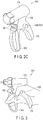
- FIG. 2C is a perspective view of the operation unit 100.
- the main body of the operation unit 100 is provided with a protrusion 120 extending from its surface in a direction perpendicular to the reference surface S.
- the protrusion 120 is preferably formed between the handle 160 and a depressed portion 130 to be described later. Therefore, the protrusion 120 is preferably formed on the grip 110 constituting part of the main body of the operation unit 100.
- the protrusion 120 is provided on each side of the grip 110. Namely, as shown in FIG.
- a first protrusion 121 which is one of the protrusions 120, is provided on the left side
- a second protrusion 122 which is the other one of the protrusions 120, is provided on the right side, when viewed from the proximal end side to the distal end side.
- the protrusion 120 does not necessarily extend perpendicularly to the reference surface S, and may extend on the angle with respect to the reference surface S.
- the treatment instrument 1 When the treatment instrument 1 is configured as a right-hand tool, i.e., when users operate the operation unit 100 only by their right hand, it is possible to provide only the first protrusion 121 without the second protrusion 122. Similarly, when the treatment instrument 1 is configured as a left-hand tool, i.e., when users operate the operation unit 100 only by their left hand, it is possible to provide only the second protrusion 122 without the first protrusion 121.
- the grip 110 includes a first surface 111 and a second surface 112, which interpose the reference surface S therebetween.
- the first surface 111 is provided with the first protrusion 121
- the second surface 112 is provided with the second protrusion 122.
- the reference surface S which is an imaginary plane, exists between the first surface 111 and the second surface 112, which are provided back to back with each other.
- a depressed portion 130 is provided in the main body of the operation unit 100 on the proximal end side between the grip 110 and the drive assembly 170.
- the depressed portion 130 is formed by providing the base part of the grip 110 on the distal end side relative to the proximal end of the drive assembly 170.
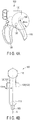
- FIG. 3 shows a state where a user holds the operation unit 100.
- the thumb of the user comes into contact with a protrusion 120.
- the thumb comes into contact with the distal end side surface of the protrusion 120, i.e., the side surface facing the handle 160, from the tip to the first joint, and with the upper side surface of the protrusion 120 from the first joint to the second joint.
- the protrusion 120 is provided within, for example, 40 mm from an area of the depressed portion 130 where the web at the bases of the user's thumb and index finger touches.
- the thumb comes into contact with the distal end side surface of the protrusion 120 from the tip to the first joint, and with the upper side surface of the protrusion 120 from the first joint to the second joint.
- FIG. 4B is a side view of the operation unit 100 viewed from the proximal end side.
- the height of the protrusion from the surface of the grip 110 is, for example, 15 mm.
- the thumb is firmly engaged with the protrusion 120.
- the above-described dimension of the protrusion 120 is an example, and is not limited to the described one.
- the operation unit 100 receives the following forces as shown in FIG. 5A .
- a grip 110 side portion of the handle 160 is pushed to the grip 110 side by the palm sides of the middle finger, ring finger, and little finger.
- the proximal end side surface of the grip 110 is pushed to the handle 160 side by the palm, in particular, the thenar eminence. Accordingly, the force with which a user closes their hand, i.e., the force with which a user bends their middle finger, ring finger, and little finger, is efficiently transmitted to move the handle 160 toward the grip 110.
- the operation unit 100 receives the following forces as shown in FIG. 5B .
- a distal end side portion of the handle 160 is pushed to the distal end side by the back sides of the middle finger, ring finger, and little finger.
- the distal end side surface of the protrusion 120 of the grip 110 is pushed to the proximal end side by the palm side of the thumb from the tip to the first joint.
- the presence of the surface of the protrusion 120 directed to the distal end side (directed to the handle 160) and receiving the force with which the thumb pushes the grip 110 to the proximal end side enables the thumb engaged with this surface of the protrusion 120 to efficiently exert the force with which the grip 110 is pushed to the proximal end side on the grip 110. Accordingly, the force with which a user opens their hand, i.e., the force with which a user stretches their middle finger, ring finger, and little finger is efficiently transmitted to move the handle 160 to the distal end side.
- the protrusion 120 does not exist.
- the circumstances under which the handle 160 is moved to the distal end side in that case will be considered.
- the force with which a user's hand pushes the grip 110 to the proximal end side is not effectively transmitted to the grip 110.
- the grip 110 does not have any surface directed to the distal end side and receiving the force with which a palm and a thumb pushes the grip 110 to the proximal end side. Therefore, when the protrusion 120 does not exist, the grip 110 is secured in the palm by the force with which the palm and the thumb hold the grip 110 therebetween, and this force is utilized to exert the pushing force to the distal end side on the grip 110.
- the hand easily slips on the grip 110, and the slip does not allow the hand opening force to be efficiently transmitted to the grip 110 or the handle 160.
- the protrusion 120 of the present embodiment improves force transmitting efficiency in transmitting the hand force to the grip 110 and the handle 160 when moving the handle 160 to the distal end side.
- the protrusion 120 is located below the depressed portion 130.
- the position of the protrusion 120 is not limited to that position.
- the protrusion 120 may be arranged above the depressed portion 130, i.e., on the drive assembly 170 side with respect to the depressed portion 130.
- the protrusion 120 is circular.
- the shape is not limited to this.
- the protrusion 120 may extend along the grip.
- the shape of the protrusion 120 may be another shape, such as an oval, a square, or a triangle.
- the protrusion 120 preferably has an upper side surface that the user's thumb touches from the first joint to the second joint, and a distal end side surface that the user's thumb touches from the tip to the first joint.
- the protrusion 120 preferably has a shape including a portion where the direction of the normal to the side surface of the protrusion 120, i.e., the component of the normal to the protrusion 120 projected on the reference surface S, is the upper direction on the proximal end side and changes to the distal end direction on the distal end side.
- the protrusion 120 preferably has a distal end side surface that the user's thumb touches from the tip to the first joint.
- the protrusion preferably has a surface directed to the handle 160.
- the protrusion 120 may have any size. Namely, as described above, as long as the protrusion 120 allows the user's thumb to be engaged therewith, the other portions of the protrusion 120 may have any shape or size, and in particular, the shape of the lower part is not limited.
- the configuration of the treatment instrument 1 is not limited to this.
- the treatment instrument 1 may be configured to allow the shaft to bend in the end effector in accordance with an operation of the handle 160.
- the treatment instrument 1 may be configured to punch out a staple in accordance with an operation of the handle 160.
- another operation may be performed in accordance with an operation of the handle 160.
- the end effector may include any mechanism on the distal end side of the shaft.
Landscapes
- Health & Medical Sciences (AREA)
- Life Sciences & Earth Sciences (AREA)
- Surgery (AREA)
- Engineering & Computer Science (AREA)
- Veterinary Medicine (AREA)
- Public Health (AREA)
- Nuclear Medicine, Radiotherapy & Molecular Imaging (AREA)
- Biomedical Technology (AREA)
- General Health & Medical Sciences (AREA)
- Animal Behavior & Ethology (AREA)
- Molecular Biology (AREA)
- Medical Informatics (AREA)
- Heart & Thoracic Surgery (AREA)
- Physics & Mathematics (AREA)
- Plasma & Fusion (AREA)
- Otolaryngology (AREA)
- Ophthalmology & Optometry (AREA)
- Mechanical Engineering (AREA)
- Dentistry (AREA)
- Surgical Instruments (AREA)
- Radiology & Medical Imaging (AREA)
Applications Claiming Priority (2)
| Application Number | Priority Date | Filing Date | Title |
|---|---|---|---|
| JP2014201279 | 2014-09-30 | ||
| PCT/JP2015/075459 WO2016052096A1 (ja) | 2014-09-30 | 2015-09-08 | 処置装置 |
Publications (2)
| Publication Number | Publication Date |
|---|---|
| EP3202349A1 true EP3202349A1 (de) | 2017-08-09 |
| EP3202349A4 EP3202349A4 (de) | 2018-03-14 |
Family
ID=55630139
Family Applications (1)
| Application Number | Title | Priority Date | Filing Date |
|---|---|---|---|
| EP15846739.9A Withdrawn EP3202349A4 (de) | 2014-09-30 | 2015-09-08 | Behandlungsvorrichtung |
Country Status (5)
| Country | Link |
|---|---|
| US (1) | US20170128095A1 (de) |
| EP (1) | EP3202349A4 (de) |
| JP (1) | JP6017736B2 (de) |
| CN (1) | CN106659528A (de) |
| WO (1) | WO2016052096A1 (de) |
Families Citing this family (3)
| Publication number | Priority date | Publication date | Assignee | Title |
|---|---|---|---|---|
| KR101333832B1 (ko) * | 2012-06-22 | 2013-12-05 | 주식회사 불불 | 가열용 취관 |
| CN107582165A (zh) * | 2017-09-29 | 2018-01-16 | 广东弘和医疗器械制造有限公司 | 一种电凝切割器 |
| CN111407401B (zh) * | 2020-04-27 | 2024-10-29 | 珠海市司迈科技有限公司 | 一种多功能微创手术钳及其操作方法 |
Family Cites Families (20)
| Publication number | Priority date | Publication date | Assignee | Title |
|---|---|---|---|---|
| US4330093A (en) * | 1980-08-08 | 1982-05-18 | Western Electric Company, Inc. | Thumb-controlled hand-held tool |
| US5190541A (en) * | 1990-10-17 | 1993-03-02 | Boston Scientific Corporation | Surgical instrument and method |
| US5458598A (en) * | 1993-12-02 | 1995-10-17 | Cabot Technology Corporation | Cutting and coagulating forceps |
| DE4431561C2 (de) * | 1994-09-05 | 1997-11-06 | Univ Ludwigs Albert | Medizinisches Handhabungsgerät |
| JPH10127651A (ja) * | 1996-09-04 | 1998-05-19 | Olympus Optical Co Ltd | 手術用処置具 |
| USD457958S1 (en) * | 2001-04-06 | 2002-05-28 | Sherwood Services Ag | Vessel sealer and divider |
| US7101371B2 (en) * | 2001-04-06 | 2006-09-05 | Dycus Sean T | Vessel sealer and divider |
| USD496997S1 (en) * | 2003-05-15 | 2004-10-05 | Sherwood Services Ag | Vessel sealer and divider |
| US8764765B2 (en) * | 2003-09-23 | 2014-07-01 | Covidien Lp | Laparoscopic instrument and related surgical method |
| WO2005037329A2 (en) * | 2003-10-17 | 2005-04-28 | Tyco Healthcare Group, Lp | Surgical stapling device with independent tip rotation |
| DE102006047204B4 (de) * | 2006-10-05 | 2015-04-23 | Erbe Elektromedizin Gmbh | Rohrschaftinstrument |
| NL1034125C2 (nl) * | 2007-07-12 | 2009-01-13 | Berkin Bv | Flowmeter van het Coriolis type. |
| USD594983S1 (en) * | 2007-10-05 | 2009-06-23 | Ethicon Endo-Surgery, Inc. | Handle assembly for surgical instrument |
| AU2008308606B2 (en) * | 2007-10-05 | 2014-12-18 | Ethicon Endo-Surgery, Inc. | Ergonomic surgical instruments |
| US9050098B2 (en) * | 2007-11-28 | 2015-06-09 | Covidien Ag | Cordless medical cauterization and cutting device |
| US8888776B2 (en) * | 2010-06-09 | 2014-11-18 | Ethicon Endo-Surgery, Inc. | Electrosurgical instrument employing an electrode |
| US8986287B2 (en) * | 2011-02-14 | 2015-03-24 | Adrian E. Park | Adjustable laparoscopic instrument handle |
| USD709194S1 (en) * | 2013-01-31 | 2014-07-15 | Ethicon Endo-Surgery, Inc. | Handle for surgical instrument |
| US10188385B2 (en) * | 2014-12-18 | 2019-01-29 | Ethicon Llc | Surgical instrument system comprising lockable systems |
| US9895148B2 (en) * | 2015-03-06 | 2018-02-20 | Ethicon Endo-Surgery, Llc | Monitoring speed control and precision incrementing of motor for powered surgical instruments |
-
2015
- 2015-09-08 WO PCT/JP2015/075459 patent/WO2016052096A1/ja not_active Ceased
- 2015-09-08 CN CN201580034660.4A patent/CN106659528A/zh active Pending
- 2015-09-08 JP JP2016526957A patent/JP6017736B2/ja active Active
- 2015-09-08 EP EP15846739.9A patent/EP3202349A4/de not_active Withdrawn
-
2017
- 2017-01-25 US US15/415,325 patent/US20170128095A1/en not_active Abandoned
Also Published As
| Publication number | Publication date |
|---|---|
| CN106659528A (zh) | 2017-05-10 |
| WO2016052096A1 (ja) | 2016-04-07 |
| EP3202349A4 (de) | 2018-03-14 |
| JP6017736B2 (ja) | 2016-11-02 |
| JPWO2016052096A1 (ja) | 2017-04-27 |
| US20170128095A1 (en) | 2017-05-11 |
Similar Documents
| Publication | Publication Date | Title |
|---|---|---|
| CN105934209B (zh) | 具有阶段式夹持的超声外科器械 | |
| EP2366345B1 (de) | Von Hand aktiviertes Ultraschallinstrument | |
| EP2837354B1 (de) | Medizinischer manipulator | |
| CN105530879B (zh) | 腹腔镜夹钳组件 | |
| EP2688496B1 (de) | Energetische schere | |
| CN101371797B (zh) | 外科用手术装置 | |
| EP2446848A1 (de) | Chirurgisches instrument | |
| EP1943969A1 (de) | Ultraschalloperationsvorrichtung | |
| KR101447266B1 (ko) | 복강경 수술장치 | |
| JP2017527407A (ja) | 取り外し可能なクランプアームを有する超音波外科用器具 | |
| US20170128095A1 (en) | Treatment instrument | |
| JP2012075604A (ja) | 処置具 | |
| US11000302B2 (en) | Grasping treatment instrument | |
| JP5645857B2 (ja) | 操作性を改良した手術器具 | |
| WO2017090191A1 (ja) | エネルギー処置具 | |
| KR20240035688A (ko) | 수술용 인스트루먼트의 엔드 툴 및 이를 구비한 전기 소작 수술용 인스트루먼트 | |
| CN107530101B (zh) | 医疗设备和超声波手术装置 | |
| JP7073277B2 (ja) | 超音波手術器具のための受動的切開機構 | |
| JP6643504B2 (ja) | 処置具 | |
| JP2000126194A (ja) | 内視鏡用処置具の操作部 | |
| WO2016152306A1 (ja) | 医療処置具 | |
| JP2017176582A (ja) | 医療用鉗子 | |
| KR20250157048A (ko) | 수술용 인스트루먼트 조작부 및 이를 구비한 전기 소작 수술용 인스트루먼트 | |
| JP4276873B2 (ja) | 超音波処置装置 | |
| JP2021122297A (ja) | 補助具 |
Legal Events
| Date | Code | Title | Description |
|---|---|---|---|
| STAA | Information on the status of an ep patent application or granted ep patent |
Free format text: STATUS: THE INTERNATIONAL PUBLICATION HAS BEEN MADE |
|
| PUAI | Public reference made under article 153(3) epc to a published international application that has entered the european phase |
Free format text: ORIGINAL CODE: 0009012 |
|
| STAA | Information on the status of an ep patent application or granted ep patent |
Free format text: STATUS: REQUEST FOR EXAMINATION WAS MADE |
|
| 17P | Request for examination filed |
Effective date: 20170418 |
|
| AK | Designated contracting states |
Kind code of ref document: A1 Designated state(s): AL AT BE BG CH CY CZ DE DK EE ES FI FR GB GR HR HU IE IS IT LI LT LU LV MC MK MT NL NO PL PT RO RS SE SI SK SM TR |
|
| AX | Request for extension of the european patent |
Extension state: BA ME |
|
| DAV | Request for validation of the european patent (deleted) | ||
| DAX | Request for extension of the european patent (deleted) | ||
| A4 | Supplementary search report drawn up and despatched |
Effective date: 20180209 |
|
| RIC1 | Information provided on ipc code assigned before grant |
Ipc: A61B 17/32 20060101ALI20180205BHEP Ipc: A61B 17/29 20060101ALI20180205BHEP Ipc: A61B 18/00 20060101AFI20180205BHEP |
|
| STAA | Information on the status of an ep patent application or granted ep patent |
Free format text: STATUS: EXAMINATION IS IN PROGRESS |
|
| 17Q | First examination report despatched |
Effective date: 20181102 |
|
| GRAP | Despatch of communication of intention to grant a patent |
Free format text: ORIGINAL CODE: EPIDOSNIGR1 |
|
| STAA | Information on the status of an ep patent application or granted ep patent |
Free format text: STATUS: GRANT OF PATENT IS INTENDED |
|
| INTG | Intention to grant announced |
Effective date: 20190819 |
|
| STAA | Information on the status of an ep patent application or granted ep patent |
Free format text: STATUS: THE APPLICATION IS DEEMED TO BE WITHDRAWN |
|
| 18D | Application deemed to be withdrawn |
Effective date: 20200103 |