EP3202478A1 - Procédé de production de filtre en nid d'abeilles - Google Patents
Procédé de production de filtre en nid d'abeilles Download PDFInfo
- Publication number
- EP3202478A1 EP3202478A1 EP15846217.6A EP15846217A EP3202478A1 EP 3202478 A1 EP3202478 A1 EP 3202478A1 EP 15846217 A EP15846217 A EP 15846217A EP 3202478 A1 EP3202478 A1 EP 3202478A1
- Authority
- EP
- European Patent Office
- Prior art keywords
- molded body
- honeycomb
- carbon
- silica
- producing
- Prior art date
- Legal status (The legal status is an assumption and is not a legal conclusion. Google has not performed a legal analysis and makes no representation as to the accuracy of the status listed.)
- Granted
Links
Images


Classifications
-
- B—PERFORMING OPERATIONS; TRANSPORTING
- B01—PHYSICAL OR CHEMICAL PROCESSES OR APPARATUS IN GENERAL
- B01D—SEPARATION
- B01D39/00—Filtering material for liquid or gaseous fluids
- B01D39/14—Other self-supporting filtering material ; Other filtering material
- B01D39/20—Other self-supporting filtering material ; Other filtering material of inorganic material, e.g. asbestos paper, metallic filtering material of non-woven wires
-
- C—CHEMISTRY; METALLURGY
- C04—CEMENTS; CONCRETE; ARTIFICIAL STONE; CERAMICS; REFRACTORIES
- C04B—LIME, MAGNESIA; SLAG; CEMENTS; COMPOSITIONS THEREOF, e.g. MORTARS, CONCRETE OR LIKE BUILDING MATERIALS; ARTIFICIAL STONE; CERAMICS; REFRACTORIES; TREATMENT OF NATURAL STONE
- C04B35/00—Shaped ceramic products characterised by their composition; Ceramics compositions; Processing powders of inorganic compounds preparatory to the manufacturing of ceramic products
- C04B35/515—Shaped ceramic products characterised by their composition; Ceramics compositions; Processing powders of inorganic compounds preparatory to the manufacturing of ceramic products based on non-oxide ceramics
- C04B35/56—Shaped ceramic products characterised by their composition; Ceramics compositions; Processing powders of inorganic compounds preparatory to the manufacturing of ceramic products based on non-oxide ceramics based on carbides or oxycarbides
- C04B35/565—Shaped ceramic products characterised by their composition; Ceramics compositions; Processing powders of inorganic compounds preparatory to the manufacturing of ceramic products based on non-oxide ceramics based on carbides or oxycarbides based on silicon carbide
-
- B—PERFORMING OPERATIONS; TRANSPORTING
- B01—PHYSICAL OR CHEMICAL PROCESSES OR APPARATUS IN GENERAL
- B01D—SEPARATION
- B01D46/00—Filters or filtering processes specially modified for separating dispersed particles from gases or vapours
-
- B—PERFORMING OPERATIONS; TRANSPORTING
- B01—PHYSICAL OR CHEMICAL PROCESSES OR APPARATUS IN GENERAL
- B01D—SEPARATION
- B01D46/00—Filters or filtering processes specially modified for separating dispersed particles from gases or vapours
- B01D46/24—Particle separators, e.g. dust precipitators, using rigid hollow filter bodies
- B01D46/2403—Particle separators, e.g. dust precipitators, using rigid hollow filter bodies characterised by the physical shape or structure of the filtering element
- B01D46/2418—Honeycomb filters
-
- B—PERFORMING OPERATIONS; TRANSPORTING
- B28—WORKING CEMENT, CLAY, OR STONE
- B28B—SHAPING CLAY OR OTHER CERAMIC COMPOSITIONS; SHAPING SLAG; SHAPING MIXTURES CONTAINING CEMENTITIOUS MATERIAL, e.g. PLASTER
- B28B3/00—Producing shaped articles from the material by using presses; Presses specially adapted therefor
- B28B3/20—Producing shaped articles from the material by using presses; Presses specially adapted therefor wherein the material is extruded
-
- C—CHEMISTRY; METALLURGY
- C04—CEMENTS; CONCRETE; ARTIFICIAL STONE; CERAMICS; REFRACTORIES
- C04B—LIME, MAGNESIA; SLAG; CEMENTS; COMPOSITIONS THEREOF, e.g. MORTARS, CONCRETE OR LIKE BUILDING MATERIALS; ARTIFICIAL STONE; CERAMICS; REFRACTORIES; TREATMENT OF NATURAL STONE
- C04B38/00—Porous mortars, concrete, artificial stone or ceramic ware; Preparation thereof
- C04B38/0006—Honeycomb structures
-
- F—MECHANICAL ENGINEERING; LIGHTING; HEATING; WEAPONS; BLASTING
- F01—MACHINES OR ENGINES IN GENERAL; ENGINE PLANTS IN GENERAL; STEAM ENGINES
- F01N—GAS-FLOW SILENCERS OR EXHAUST APPARATUS FOR MACHINES OR ENGINES IN GENERAL; GAS-FLOW SILENCERS OR EXHAUST APPARATUS FOR INTERNAL-COMBUSTION ENGINES
- F01N3/00—Exhaust or silencing apparatus having means for purifying, rendering innocuous, or otherwise treating exhaust
- F01N3/02—Exhaust or silencing apparatus having means for purifying, rendering innocuous, or otherwise treating exhaust for cooling, or for removing solid constituents of, exhaust
- F01N3/021—Exhaust or silencing apparatus having means for purifying, rendering innocuous, or otherwise treating exhaust for cooling, or for removing solid constituents of, exhaust by means of filters
- F01N3/022—Exhaust or silencing apparatus having means for purifying, rendering innocuous, or otherwise treating exhaust for cooling, or for removing solid constituents of, exhaust by means of filters characterised by specially adapted filtering structure, e.g. honeycomb, mesh or fibrous
-
- C—CHEMISTRY; METALLURGY
- C04—CEMENTS; CONCRETE; ARTIFICIAL STONE; CERAMICS; REFRACTORIES
- C04B—LIME, MAGNESIA; SLAG; CEMENTS; COMPOSITIONS THEREOF, e.g. MORTARS, CONCRETE OR LIKE BUILDING MATERIALS; ARTIFICIAL STONE; CERAMICS; REFRACTORIES; TREATMENT OF NATURAL STONE
- C04B2111/00—Mortars, concrete or artificial stone or mixtures to prepare them, characterised by specific function, property or use
- C04B2111/00474—Uses not provided for elsewhere in C04B2111/00
- C04B2111/00793—Uses not provided for elsewhere in C04B2111/00 as filters or diaphragms
-
- C—CHEMISTRY; METALLURGY
- C04—CEMENTS; CONCRETE; ARTIFICIAL STONE; CERAMICS; REFRACTORIES
- C04B—LIME, MAGNESIA; SLAG; CEMENTS; COMPOSITIONS THEREOF, e.g. MORTARS, CONCRETE OR LIKE BUILDING MATERIALS; ARTIFICIAL STONE; CERAMICS; REFRACTORIES; TREATMENT OF NATURAL STONE
- C04B2111/00—Mortars, concrete or artificial stone or mixtures to prepare them, characterised by specific function, property or use
- C04B2111/00474—Uses not provided for elsewhere in C04B2111/00
- C04B2111/0081—Uses not provided for elsewhere in C04B2111/00 as catalysts or catalyst carriers
-
- C—CHEMISTRY; METALLURGY
- C04—CEMENTS; CONCRETE; ARTIFICIAL STONE; CERAMICS; REFRACTORIES
- C04B—LIME, MAGNESIA; SLAG; CEMENTS; COMPOSITIONS THEREOF, e.g. MORTARS, CONCRETE OR LIKE BUILDING MATERIALS; ARTIFICIAL STONE; CERAMICS; REFRACTORIES; TREATMENT OF NATURAL STONE
- C04B2235/00—Aspects relating to ceramic starting mixtures or sintered ceramic products
- C04B2235/02—Composition of constituents of the starting material or of secondary phases of the final product
- C04B2235/30—Constituents and secondary phases not being of a fibrous nature
- C04B2235/34—Non-metal oxides, non-metal mixed oxides, or salts thereof that form the non-metal oxides upon heating, e.g. carbonates, nitrates, (oxy)hydroxides, chlorides
- C04B2235/3418—Silicon oxide, silicic acids or oxide forming salts thereof, e.g. silica sol, fused silica, silica fume, cristobalite, quartz or flint
-
- C—CHEMISTRY; METALLURGY
- C04—CEMENTS; CONCRETE; ARTIFICIAL STONE; CERAMICS; REFRACTORIES
- C04B—LIME, MAGNESIA; SLAG; CEMENTS; COMPOSITIONS THEREOF, e.g. MORTARS, CONCRETE OR LIKE BUILDING MATERIALS; ARTIFICIAL STONE; CERAMICS; REFRACTORIES; TREATMENT OF NATURAL STONE
- C04B2235/00—Aspects relating to ceramic starting mixtures or sintered ceramic products
- C04B2235/02—Composition of constituents of the starting material or of secondary phases of the final product
- C04B2235/30—Constituents and secondary phases not being of a fibrous nature
- C04B2235/38—Non-oxide ceramic constituents or additives
- C04B2235/3817—Carbides
- C04B2235/3826—Silicon carbides
-
- C—CHEMISTRY; METALLURGY
- C04—CEMENTS; CONCRETE; ARTIFICIAL STONE; CERAMICS; REFRACTORIES
- C04B—LIME, MAGNESIA; SLAG; CEMENTS; COMPOSITIONS THEREOF, e.g. MORTARS, CONCRETE OR LIKE BUILDING MATERIALS; ARTIFICIAL STONE; CERAMICS; REFRACTORIES; TREATMENT OF NATURAL STONE
- C04B2235/00—Aspects relating to ceramic starting mixtures or sintered ceramic products
- C04B2235/02—Composition of constituents of the starting material or of secondary phases of the final product
- C04B2235/30—Constituents and secondary phases not being of a fibrous nature
- C04B2235/42—Non metallic elements added as constituents or additives, e.g. sulfur, phosphor, selenium or tellurium
- C04B2235/422—Carbon
-
- C—CHEMISTRY; METALLURGY
- C04—CEMENTS; CONCRETE; ARTIFICIAL STONE; CERAMICS; REFRACTORIES
- C04B—LIME, MAGNESIA; SLAG; CEMENTS; COMPOSITIONS THEREOF, e.g. MORTARS, CONCRETE OR LIKE BUILDING MATERIALS; ARTIFICIAL STONE; CERAMICS; REFRACTORIES; TREATMENT OF NATURAL STONE
- C04B2235/00—Aspects relating to ceramic starting mixtures or sintered ceramic products
- C04B2235/65—Aspects relating to heat treatments of ceramic bodies such as green ceramics or pre-sintered ceramics, e.g. burning, sintering or melting processes
- C04B2235/658—Atmosphere during thermal treatment
- C04B2235/6583—Oxygen containing atmosphere, e.g. with changing oxygen pressures
- C04B2235/6584—Oxygen containing atmosphere, e.g. with changing oxygen pressures at an oxygen percentage below that of air
Definitions
- the present invention relates to a method for producing a honeycomb filter.
- PM Particulates
- honeycomb filter to purify exhaust gas by capturing PM
- a honeycomb filter which is formed of a ceramic block including multiple honeycomb fired bodies that are combined with each other in which the honeycomb fired bodies each include a large number of cells longitudinally arranged in parallel to one another across porous cell partition walls.
- Patent Literature 1 discloses a method for producing such a honeycomb filter.
- raw materials such as silicon carbide powder and an organic binder are mixed to obtain a raw material composition as a molded body raw material, and the molded body raw material is extruded into a honeycomb molded body.
- the honeycomb molded body is degreased and fired into a honeycomb fired body, and multiple honeycomb fired bodies are bonded together into a ceramic block.
- the ceramic block is cut, and a peripheral coat layer is formed thereon.
- a honeycomb filter is produced.
- the raw material composition contains a pore-forming agent and the like, in addition to the organic binder.
- the pore-forming agent include organic pore-forming agents such as spherical acrylic particles and graphite and balloons containing oxide ceramic such as silica.
- Patent Literature 1 JP-A 2007-230855
- the organic materials such as an organic binder and an organic pore-forming agent, the pore-forming agent containing oxide ceramic, and the like in the honeycomb molded body are separated from the honeycomb molded body and discharged from the furnace, but some of these materials remain in the furnace.
- the organic materials, carbon, silica, and the like remaining in the furnace stay in the atmospheric gas in the degreasing step and the firing step. Thus, it is difficult to maintain the constant degreasing and firing conditions.
- the silica and the like are deposited as scale in the furnace, interfering with the transfer of products or the like. Thus, it is desirable to minimize the accumulation of various materials on the inner wall surface of the furnace.
- the present invention is made to solve the above problems and aims to provide a method for producing a honeycomb filter in which scattering of organic decomposed materials, carbon, silica, and the like can be suppressed in the degreasing step and the firing step to prevent the attachment of the organic decomposed materials, carbon, silica, and the like to the furnace walls, and the honeycomb filter can be efficiently produced under stable conditions.
- the method for producing a honeycomb filter of the present invention includes a molded body raw material preparing step of mixing silicon carbide powder, organic additives at least including an organic binder, and a silica-based pore-forming agent to prepare a raw material composition as a molded body raw material; a molded body producing step of extruding the prepared molded body raw material into a honeycomb molded body; a degreasing step of degreasing the produced honeycomb molded body; and a firing step of firing the degreased honeycomb molded body, wherein at the end of the degreasing step, the degreased honeycomb molded body contains silica including the silica-based pore-forming agent and carbon, and in the firing step, the silica is allowed to react with the carbon to synthesize silicon carbide.
- the method for producing a honeycomb filter of the present invention is designed in such a manner that the degreased honeycomb molded body contains the silica including the silica-based pore-forming agent and carbon at the end of the degreasing step.
- the silica reacts with the carbon to synthesize silicon carbide.
- the silicon carbide fired body includes cell partition walls. The synthesized silicon carbide becomes a part of the cell partition walls and improves the mechanical characteristics of the cell partition walls.
- the carbon and the silica are consumed in the above reaction.
- the scattering of the organic decomposed materials, carbon, silica, and the like can be suppressed in the degreasing step and the firing step, and the attachment of the organic decomposed materials, carbon, silica, and the like to the furnace walls can be suppressed.
- the honeycomb filter can be efficiently produced under stable conditions.
- carbon powder is added to the raw material composition.
- the addition of the carbon powder allows the carbon to react with the silica to synthesize silicon carbide in the firing step, thus suppressing the attachment of the organic decomposed materials, carbon, silica, and the like to the furnace walls.
- oxidation reaction of carbon or the organic additives in the honeycomb molded body is suppressed to allow a carbon component to remain in the degreased honeycomb molded body.
- the oxygen concentration in the gas surrounding the honeycomb molded body is reduced or the honeycomb molded body is degreased in an oxygen-free atmosphere, thus allowing the carbon component to remain in the degreased honeycomb molded body.
- the carbon is allowed to react with the silica to synthesize silicon carbide in the firing step, thus suppressing the attachment of the organic decomposed materials, carbon, silica, and the like to the furnace walls.
- the degreasing step is performed in a completely inert gas atmosphere.
- the degreasing step is performed in a completely inert gas atmosphere, so that the organic additives such as the organic binder are less likely to be oxidatively decomposed and are mainly pyrolyzed, thus easily being converted into carbon.
- the carbon is allowed to react with the silica to synthesize silicon carbide in the firing step, thus suppressing the attachment of the organic decomposed materials, carbon, silica, and the like to the furnace walls.
- the firing step is performed in a completely inert gas atmosphere.
- the degreasing step and the firing step can be performed in an inert gas atmosphere.
- the degreasing step and the firing step can be performed in one furnace, simplifying the steps and enabling a significant reduction in the required amount of heat.
- the honeycomb filter can be produced at lower cost.
- the carbon is allowed to react with the silica to synthesize silicon carbide.
- the molar ratio of carbon to silica (carbon/silica) in the degreased honeycomb molded body is 1 to 3.
- the carbon reacts with the silica to form silicon carbide in the firing step, and thus there is hardly any residual silica or residual carbon in the resulting fired body. Therefore, it is possible to produce a porous silicon carbide fired body having good characteristics, and the resulting honeycomb filter can exhibit sufficient performance as a honeycomb filter.
- the degreasing step and the firing step are performed in one batch furnace.
- the degreasing step and the firing step can be performed in an inert gas atmosphere, so that the degreasing step and the firing step can be continuously performed in one batch furnace, and the honeycomb filter can be produced more efficiently at lower cost.
- the degreasing step and the firing step are performed in one continuous furnace, and the continuous furnace is provided with a degreasing area and a firing area.
- the degreasing step and the firing step can be performed in an inert gas atmosphere, so that the degreasing step and the firing step can be performed in one continuous furnace provided with the degreasing area and the firing area, and the degreasing step and the firing step can be performed while honeycomb molded bodies are continuously supplied to and delivered from the continuous furnace.
- the honeycomb filter can be produced more efficiently at lower cost.
- the organic additives further include an organic pore-forming agent.
- the organic additives further include an organic pore-forming agent in the method for producing a honeycomb filter of the present invention
- the organic pore-forming agent can be carbonized in the degreased step, and the resulting carbon is allowed to react with the silica, thus preventing the carbon and the silica from remaining in the honeycomb fired body that constitutes the honeycomb filter.
- the method for producing a honeycomb filter of the present invention includes a molded body raw material preparing step of mixing silicon carbide powder, organic additives at least including an organic binder, and silica-based pore-forming agent to prepare a raw material composition as a molded body raw material; a molded body producing step of extruding the prepared molded body raw material into a honeycomb molded body; a degreasing step of degreasing the produced honeycomb molded body; and a firing step of firing the degreased honeycomb molded body, wherein at the end of the degreasing step, the degreased honeycomb molded body contains silica including the silica-based pore-forming agent and carbon, and in the firing step, the silica is allowed to react with the carbon to synthesize silicon carbide.
- the method for producing a honeycomb filter of the present invention includes a molded body raw material preparing step, a molded body producing step, a degreasing step, and a firing step.
- the method for producing a honeycomb filter including the above steps is described below for each step.
- silicon carbide powder, organic additives at least including an organic binder, and silica-based pore-forming agent are mixed to prepare a raw material composition as a molded body raw material.
- Two types of silicon carbide powder having different average particle sizes may be a combination of silicon carbide powder having an average particle size of 0.3 to 50 ⁇ m and silicon carbide having an average particle size of about 0.1 to 1.0 ⁇ m. Such a combination facilitates the production of a porous silicon carbide fired body.
- organic additives examples include a liquid dispersion medium, a plasticizer, and a lubricant, in addition to the organic binder.
- organic binder examples include methylcellulose, carboxymethyl cellulose, hydroxyethyl cellulose, polyethylene glycol, phenolic resin, and epoxy resin. Preferred among these is methylcellulose.
- liquid dispersion medium examples include alcohols such as methanol and organic solvents such as benzene.
- Water may be used as a liquid dispersion medium other than the organic additives.
- plasticizer Any plasticizer may be used. Examples thereof include glycerin.
- the lubricant is not particularly limited. Examples thereof include polyoxyalkylene-based compounds such as polyoxyethylene alkyl ether and polyoxypropylene alkyl ether. Specific examples of the lubricant include polyoxyethylene monobutyl ether and polyoxypropylene monobutyl ether.
- the raw material composition contains a silica-based pore-forming agent.
- the silica-based pore-forming agent include balloons that are fine hollow spheres. Specific examples of balloons include silica balloon, glass microballoon, shirasu balloon, fly ash balloon (FA balloon), and mullite balloon.
- the use of such a pore-forming agent facilitates the control of the porosity of the honeycomb filter to be produced.
- the silica-based pore-forming agent is added to the raw material composition to control the porosity of the honeycomb filter and to cause reaction between the silica and the residual carbon in the degreased honeycomb molded body so as to remove the carbon and synthesize silicon carbide.
- carbon powder such as graphite powder may be added to the raw material composition.
- the average particle size of the carbon powder to be added is preferably 0.5 to 40 ⁇ m.
- the addition of the carbon powder causes reaction between the carbon and the silica to synthesize silicon carbide in the firing step, thus suppressing the attachment of the organic decomposed materials, carbon, silica, and the like to the furnace walls.
- the molded body raw material is prepared by mixing the silicon carbide powder, the organic binder, the silica-based pore-forming agent, and water as the liquid dispersion medium in a wet mixer. Materials such as the carbon powder, the plasticizer, and the lubricant may be added at this point, if necessary.
- the prepared molded body raw material is extruded into a honeycomb molded body.
- the obtained molded body raw material is fed into an extruder and extruded into a rectangular pillar-shaped continuous body which is then cut in a predetermined length, thus producing a honeycomb molded body having a large number of through-holes arranged longitudinally in parallel to one another.
- the honeycomb molded body is dried by a dryer into a dried honeycomb molded body.
- a predetermined amount of plug material paste is placed at one end of each of the through-holes constituting the dried honeycomb molded body to plug the cells.
- a cell plugging mask is placed on an end face of the honeycomb molded body (i.e., each cut face obtained by cutting both ends), and the plug material paste is placed only in the cells that need to be plugged.
- the plug material paste is then dried. Through these steps, the honeycomb molded body in which one end of each cell is plugged is produced.
- Fig. 1(a) is a schematic perspective view of a honeycomb molded body in which one end of each cell is plugged; and Fig. 1(b) is a cross-sectional view of the honeycomb molded body of Fig. 1(a) taken along line A-A.
- a produced honeycomb molded body 200 includes a large number of cells 210 arranged longitudinally in parallel to one another in which one end of each cell 210 is plugged with a plug 220 and a wall 230 is formed between the cells 210.
- the honeycomb molded body 200 in which each cell is plugged is heated in a degreasing furnace for degreasing.
- the degreasing step has been performed by heating at 300°C to 650°C in an oxygen-containing atmosphere to oxidatively decompose and completely remove the organic materials.
- oxidation reaction of carbon or the organic additives in the honeycomb molded body is suppressed in the degreasing step to allow the carbon component to remain in the degreased honeycomb molded body.
- Any method may be used to suppress oxidation reaction of carbon or the like in the honeycomb molded body to allow the carbon component to remain in the degreased honeycomb molded body.
- the amount of oxygen in the degreasing atmosphere may be reduced.
- the degreasing step is performed by heating the honeycomb molded body at 200°C to 650°C in a completely inert gas atmosphere.
- completely inert gas atmosphere refers to an inert gas atmosphere completely free of oxygen, hydrogen, or the like. Examples thereof include an argon atmosphere and a nitrogen atmosphere.
- the organic additives are pyrolyzed in a completely inert gas atmosphere as described above.
- the organic additives when the organic additives contain hydrogen or oxygen in the compounds, the organic additives are pyrolyzed into hydrocarbons or oxides which are separated from the honeycomb molded body 200; however, some of the organic additives remain as carbon and carbon compounds in the honeycomb molded body 200. In the case where the honeycomb molded body prior to degreasing contains carbon powder, the carbon powder will remain as is in the honeycomb molded body.
- the degreased honeycomb molded body 200 is fired in the firing step.
- the firing step is usually performed at 1400°C to 2200°C, preferably in a completely inert gas atmosphere.
- the degreased honeycomb molded body contains silica including the silica-based pore-forming agent and carbon, the silica reacts with the carbon to synthesize silicon carbide in the firing step.
- the silicon carbide fired body includes cell partition walls. The synthesized silicon carbide becomes a part of the cell partition walls and improves the mechanical characteristics of the cell partition walls.
- the carbon and the silica are consumed in the above reaction.
- the scattering of the organic decomposed materials, carbon, silica, and the like can be suppressed in the degreasing step and the firing step, and the attachment of the organic decomposed materials, carbon, silica, and the like to the furnace walls can be suppressed.
- the honeycomb filter can be efficiently produced under stable conditions.
- the degreasing step is preferably performed in a completely inert gas atmosphere.
- the degreasing step and the firing step can be performed in the same atmospheric gas. This means that the degreasing step and the firing step can be performed in one batch furnace and that the degreasing step and the firing step can be performed in one continuous furnace provided with a degreasing area and a firing area.
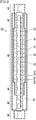
- Fig. 2 is a schematic vertical sectional view of a continuous heating furnace according to the present invention, which is cut in a vertical plane along the longitudinal direction thereof.
- Fig. 3 is a schematic cross-sectional view of the continuous heating furnace according to the present invention, which is cut in a plane perpendicular to the longitudinal direction thereof.
- a deaeration area 41, a degreasing area 42, a firing area 43, a slow cooling area 44, a cooling area 45, and a deaeration area 46 are provided in this order from the inlet.
- the deaeration area 41 is provided to change the atmosphere inside and around the honeycomb molded body 200 to be carried in. After the honeycomb molded body 200 is carried on a conveyance unit 39 or the like into the deaeration area 41, the deaeration area 41 is temporarily vacuumed, and inert gas is subsequently introduced, whereby the atmosphere inside and around the honeycomb molded body 200 is changed to an inert gas atmosphere.
- the temperature of the honeycomb molded body 200 is increased to 200°C to 650°C by using heaters or with the heat of the firing area for pyrolysis of the organic additives in the honeycomb molded body 200.
- the heating step in the degreasing area 42 corresponds to the degreasing step.
- the temperature is further increased to 650°C or higher for firing the honeycomb molded body at 1400°C to 2200°C.
- the fired honeycomb molded body 200 is gradually cooled in the slow cooling area 44, and is further cooled to near room temperature in the cooling area 45.
- the inert gas is replaced by air, and the honeycomb molded body 200 is carried out from the deaeration area 46. Thereby, a sequence of the degreasing treatment and the firing treatment of the honeycomb molded body 200 is completed.
- the degreasing area 42 and the firing area 43 where the honeycomb molded body 200 is degreased and fired respectively, include a cylindrical muffle 31 formed to provide a space for accommodating the honeycomb molded body 200, heaters 32 provided at predetermined intervals above and below the muffle 31, an insulating material 33 provided so as to surround the muffle 31 and the heaters 32; and a refractory material 34 provided outside the insulating material 33.
- the atmosphere in the continuous heating furnace 30 is separated from the surrounding atmosphere by the refractory material 34.
- the heaters 32 are provided in the firing area 43 and, if necessary, in the degreasing area 42.
- the muffle 31 is supported by a supporting member (not shown) at its entire bottom and is configured in such a manner that it can transfer the honeycomb molded body 200.
- the muffle 31 is provided in the entire region excluding the deaeration areas 41 and 46.
- a conveying means such as a conveyor belt may be provided inside the muffle 31. With the conveying means, the honeycomb molded body 200 can be automatically conveyed.
- the insulating material 33 is provided in the degreasing area 42, the firing area 43, and the slow cooling area 44. In the firing area 43, the insulating material 33 is provided further outside the heaters 32 and is suitably fixed by fixtures. On the outermost side, the refractory material 34 is provided in the entire region excluding the deaeration area 41.
- the refractory material 34 is provided with a gas inlet tube 37 for filling the inside of the heating furnace with an inert gas and a gas exhaust tube 38 for discharging the inert gas.
- the degreasing step and the firing step can also be performed in one batch furnace.
- a batch furnace can be constructed as follows: the heating furnace is formed in a box shape with the refractory material 34; only a portion used as the firing area 43 of the continuous heating furnace is placed inside; an openable door or the like is attached as a port for inlet and outlet; and the inside of the refractory material 34 is surrounded by an insulating material or the like.
- an inert gas is introduced into the furnace and the temperature is gradually increased for degreasing, followed by a further increase in the temperature for firing, for example.
- the degreasing step and the firing step are performed in one batch furnace or one continuous furnace has been described, but the structure of the batch furnace or the continuous furnace is not limited to the one described above, and the batch furnace having a different structure or the continuous furnace having a different structure may be used.
- the ratio (%) of the weight of the residual carbon in the honeycomb molded body 200 before reaction with the silica or the like in the degreasing step and the subsequent firing step to the total weight of the organic materials is herein referred to as the residual carbon ratio.
- the residual carbon ratio varies depending on the type of organic materials.
- the amount of residual carbon in the honeycomb molded body 200 can be adjusted by selecting the type and amount of the organic additives.
- the amount of residual carbon in the honeycomb molded body 200 can also be adjusted by adding carbon powder.
- the molar ratio of carbon to silica (carbon/silica) in the degreased honeycomb molded body is 1 to 3.
- the silica is present in an amount of 60 g relative to 36 g of the carbon, provided that they react with each other in an ideal manner as shown in the reaction formula (1).
- the molar ratio of carbon to silica is 1 to 3, considering the fact that actually the reaction of the silica with the carbon first produces SiO having a relatively low melting point and the SiO reacts with the carbon to produce SiC.
- the raw material composition may contain carbon powder or an organic pore-forming agent as an organic additive as described above.
- an organic pore-forming agent facilitates the control of the porosity of the honeycomb filter to be produced.
- a portion of the organic pore-forming agent is also converted into carbon, and the carbon reacts with the silica, thus producing SiC.
- a portion of the carbon is converted into CO by the reaction with the silica and the CO is separated from the honeycomb molded body, resulting in the formation of pores.
- the organic pore-forming agent include spherical acrylic particles and graphite.
- a porous honeycomb fired body can be produced through the degreasing step and the firing step.
- the structure of the honeycomb fired body is basically the same as that of the honeycomb molded body 200 shown in Fig. 1 .
- a sealing material paste is applied to lateral sides of each honeycomb fired body to form a sealing material paste layer, and these honeycomb fired bodies are sequentially stacked on one another with the sealing material paste layer therebetween. This procedure is repeated to produce an aggregate of a predetermined number of the honeycomb fired bodies that are combined together.
- the sealing material paste may be a mixture of an inorganic binder, an organic binder, and inorganic fibers and/or inorganic particles, for example.
- the aggregate of the honeycomb fired bodies is heated to solidify the sealing material paste layer by drying into a sealing material layer (adhesive layer). Subsequently, the aggregate of the honeycomb fired bodies is cut with a diamond cutter or the like into a ceramic block. The sealing material paste is applied to the outer periphery of the ceramic block and solidified by drying into a coat layer, whereby a honeycomb filter can be produced.
- Fig. 4 is a perspective view of a honeycomb filter produced by the method for producing a honeycomb filter of the present invention.
- Fig. 5(a) is a perspective view of the honeycomb fired body that constitutes the honeycomb filter of Fig. 4 ; and
- Fig. 5(b) is a cross-sectional view of the honeycomb fired body of Fig. 5(a) taken along line B-B.
- a honeycomb filter 10 of the present invention includes a round pillar-shaped ceramic block 15 in which multiple porous honeycomb fired bodies 20 made of silicon carbide are combined with one another with an adhesive layer 11 therebetween.
- the ceramic block 15 includes a coat layer 12 formed therearound.
- the ceramic block has a round pillar shape.
- the shape of the ceramic block is not limited to the round pillar shape as long as it is a pillar shape. It may be any other shape such as a cylindroid shape or a rectangular pillar shape.
- the honeycomb fired body 20 is produced by degreasing and firing the honeycomb molded body 200 shown in Fig. 1(a) and 1(b) .
- a large number of cells 21 are longitudinally arranged in parallel to one another, and one of the ends of each cell 21 is plugged.
- each cell partition wall 23 separating the cells 21 from each other functions as a filter.
- each cell 21 formed in the honeycomb fired body 20 is plugged with a plug 22 at one end on the exhaust gas inlet side or the exhaust gas outlet side. Exhaust gas that has flowed into one of the cells 21 inevitably passes through the cell partition wall 23 separating the cells 21 from each other, and then flows out from another cell 21.
- the honeycomb filter having the structure described above captures PM such as soot contained in exhaust gas emitted from an internal combustion engine and can thus purify the exhaust gas.
- the residual carbon from the degreasing treatment in a completely inert gas atmosphere reacts with the silica and is thus converted into silicon carbide in the firing step.
- the synthesized silicon carbide tends to aggregate in a neck portion where silicon carbide particles are bonded to each other, and plays the role of improving the mechanical characteristics of the produced honeycomb fired body.
- the carbon and the silica are consumed in the above reaction.
- the scattering of the organic decomposed materials, carbon, silica, and the like can be suppressed in the degreasing step and the firing step to suppress the attachment of the organic decomposed materials, carbon, silica, and the like to the furnace walls, and the honeycomb filter can be efficiently produced under stable conditions.
- the degreasing step and the firing step can be performed in one furnace, enabling a significant reduction in the required amount of heat.
- the honeycomb filter can be produced at lower cost.
- the process can be simplified, the risk of breaking the honeycomb molded body during transportation is eliminated, and the honeycomb filter can be produced efficiently.
- a mixture was obtained by mixing 40.8% by weight of silicon carbide coarse powder having an average particle size of 22 ⁇ m and 11.6% by weight of silicon carbide fine powder having an average particle size of 0.5 ⁇ m.
- an organic binder methylcellulose
- a lubricant UNILUB available from NOF Corporation
- 1.3% by weight of glycerin 1.3% by weight of glycerin
- 17.5% by weight of a pore-forming agent siliconca balloons
- 7.0% by weight of graphite powder having an average particle size of 1 ⁇ m, and 14.4% by weight of water The resulting mixture was kneaded into a molded body raw material.
- the molded body raw material obtained above was extruded into a raw honeycomb molded body.
- the raw honeycomb molded body was dried using a microwave dryer into a dried honeycomb molded body.
- a plug material paste was placed in predetermined cells of the dried honeycomb molded body to plug the cells, thus obtaining a honeycomb molded body with plugged cells shown in Fig. 1(a) and 1(b) .
- the molded body raw material was used as the plug material paste.
- the dried honeycomb molded body including the plug material paste was dried again by the dryer.
- honeycomb molded bodies were placed on a conveyance unit and carried into a batch furnace, and nitrogen was introduced into the furnace. Once the temperature was raised to 400°C in a nitrogen atmosphere under normal pressure, the heating was stopped for degreasing. Then, argon was introduced into the same batch furnace to replace the nitrogen gas by the argon gas without moving the degreased honeycomb molded body, and the degreased honeycomb molded body was fired at 2200°C in an argon atmosphere under normal pressure for three hours, whereby a honeycomb fired body was produced.
- the obtained honeycomb fired body was formed of a porous silicon carbide sintered body.
- the porosity was 42%, the average pore diameter was 9 ⁇ m, the size was 34.3 mm ⁇ 34.3 mm ⁇ 150 mm, the number of cells (cell density) was 31 pcs/cm 2 (200 pcs/inch 2 ), the cell partition wall thickness was 0.1016 mm, and the outer wall thickness was 0.3 mm.
- honeycomb fired bodies obtained through the above steps were used to produce a honeycomb structured body.
- honeycomb fired bodies An adhesive material paste was applied to predetermined lateral sides of each honeycomb fired body, and 36 (6 vertically ⁇ 6 transversely) honeycomb fired bodies were bonded together with the adhesive material paste therebetween, whereby an aggregate of the honeycomb fired bodies was produced.
- the aggregate of the honeycomb fired bodies was heated at 180°C for 20 minutes to solidify the adhesive material paste by drying, whereby a rectangular pillar-shaped ceramic block having a 1-mm-thick adhesive layer was produced.
- the periphery of the rectangular pillar-shaped ceramic block was cut with a diamond cutter to produce a round pillar-shaped ceramic block having a diameter of 198 mm.
- a peripheral coat material paste was applied to the periphery of the round pillar-shaped ceramic block, and the peripheral coat material paste was solidified by heating at 120°C to form a 1.0-mm-peripheral coat layer on the periphery of the ceramic block.
- the adhesive material paste was used as the peripheral coat material paste.
- a honeycomb fired body was produced in the same manner as in Example 1, except that in the molded body raw material preparing step, a mixture was obtained by mixing 41.4% by weight of silicon carbide coarse powder having an average particle size of 22 ⁇ m and 17.7% by weight of silicon carbide fine powder having an average particle size of 0.5 ⁇ m; to the mixture were added 5.1% by weight of an organic binder (methylcellulose), 2.1% by weight of a lubricant (UNILUB available from NOF Corporation), 1.4% by weight of glycerin, 5.8% by weight of silica powder, 10.7% by weight of starch, and 15.8% by weight of water; and the resulting mixture was kneaded into a molded body raw material.
- an organic binder methylcellulose
- a lubricant UNILUB available from NOF Corporation
- a mixture was obtained by mixing 54.5% by weight of silicon carbide coarse powder having an average particle size of 22 ⁇ m and 23.4% by weight of silicon carbide fine powder having an average particle size of 0.5 ⁇ m. To the mixture were added 4.3% by weight of an organic binder (methylcellulose), 2.6% by weight of a lubricant (UNILUB available from NOF Corporation), 1.2% by weight of glycerin, and 14.0% by weight of water. The resulting mixture was kneaded into a molded body raw material.
- an organic binder methylcellulose
- a lubricant UNILUB available from NOF Corporation
- the obtained molded body raw material was extruded into a raw honeycomb molded body.
- the raw honeycomb molded body was dried by a microwave dryer into a dried honeycomb molded body.
- a plug material paste was placed in predetermined cells of the dried honeycomb molded body to plug the cells, thus obtaining a honeycomb molded body with plugged cells shown in Fig. 1(a) and 1(b) .
- the molded body raw material was used as a plug material paste. After plugging the cells, the dried honeycomb molded body including the plug material paste was dried again by the dryer.
- the honeycomb molded body was carried on a conveyance unit into the degreasing furnace for degreasing at 500°C in air (degreasing treatment).
- the degreased honeycomb molded body was cooled in the degreasing furnace, carried out from the degreasing furnace, and carried into the firing furnace.
- the degreased honeycomb molded body was fired at 2200°C in an argon atmosphere under normal pressure for three hours, whereby a honeycomb fired body was produced.
- the obtained honeycomb fired body was formed of a porous silicon carbide sintered body.
- the porosity was 42%, the average pore diameter was 9 ⁇ m, the size was 34.3 mm ⁇ 34.3 mm ⁇ 150 mm, the number of cells (cell density) was 31 pcs/cm 2 (200 pcs/inch 2 ), the cell partition wall thickness was 0.1015 mm, and the outer wall thickness was 0.3 mm.
- a honeycomb filter was produced in the same manner as in Example 1, using the honeycomb fired bodies obtained through the above steps.
Landscapes
- Chemical & Material Sciences (AREA)
- Engineering & Computer Science (AREA)
- Ceramic Engineering (AREA)
- Chemical Kinetics & Catalysis (AREA)
- Manufacturing & Machinery (AREA)
- Organic Chemistry (AREA)
- Mechanical Engineering (AREA)
- Structural Engineering (AREA)
- Materials Engineering (AREA)
- General Engineering & Computer Science (AREA)
- Geometry (AREA)
- Physics & Mathematics (AREA)
- Geology (AREA)
- Life Sciences & Earth Sciences (AREA)
- Combustion & Propulsion (AREA)
- Filtering Materials (AREA)
- Ceramic Products (AREA)
Applications Claiming Priority (2)
| Application Number | Priority Date | Filing Date | Title |
|---|---|---|---|
| JP2014198667A JP2016069208A (ja) | 2014-09-29 | 2014-09-29 | ハニカムフィルタの製造方法 |
| PCT/JP2015/077427 WO2016052459A1 (fr) | 2014-09-29 | 2015-09-29 | Procédé de production de filtre en nid d'abeilles |
Publications (3)
| Publication Number | Publication Date |
|---|---|
| EP3202478A1 true EP3202478A1 (fr) | 2017-08-09 |
| EP3202478A4 EP3202478A4 (fr) | 2018-04-04 |
| EP3202478B1 EP3202478B1 (fr) | 2019-05-01 |
Family
ID=55630487
Family Applications (1)
| Application Number | Title | Priority Date | Filing Date |
|---|---|---|---|
| EP15846217.6A Active EP3202478B1 (fr) | 2014-09-29 | 2015-09-29 | Procédé de production de filtre en nid d'abeilles |
Country Status (3)
| Country | Link |
|---|---|
| EP (1) | EP3202478B1 (fr) |
| JP (1) | JP2016069208A (fr) |
| WO (1) | WO2016052459A1 (fr) |
Family Cites Families (9)
| Publication number | Priority date | Publication date | Assignee | Title |
|---|---|---|---|---|
| JP4455708B2 (ja) * | 2000-01-17 | 2010-04-21 | 日本碍子株式会社 | ハニカム構造体及びその製造方法 |
| WO2003024892A1 (fr) * | 2001-09-21 | 2003-03-27 | Stobbe Tech Holding A/S | Structures ceramiques poreuses et leur procede de preparation |
| JP3999001B2 (ja) * | 2002-03-08 | 2007-10-31 | 日本碍子株式会社 | ハニカム構造体及びそれを収納してなるキャニング構造体 |
| JP4293753B2 (ja) * | 2002-03-19 | 2009-07-08 | 日本碍子株式会社 | ハニカムフィルター |
| JP4227347B2 (ja) * | 2002-03-29 | 2009-02-18 | 日本碍子株式会社 | 多孔質材料及びその製造方法 |
| JP2007244993A (ja) * | 2006-03-15 | 2007-09-27 | National Institute Of Advanced Industrial & Technology | セラミック担体、セラミック触媒体およびその製造方法 |
| JP5199618B2 (ja) * | 2006-09-14 | 2013-05-15 | イビデン株式会社 | ハニカム構造体の製造方法 |
| DE602006014830D1 (de) * | 2006-09-14 | 2010-07-22 | Ibiden Co Ltd | Verfahren zur Herstellung eines Wabenkörpers und Zusammensetzung für Sinterwabenkörper |
| JP2009256175A (ja) * | 2008-03-27 | 2009-11-05 | Ibiden Co Ltd | ハニカム構造体の製造方法 |
-
2014
- 2014-09-29 JP JP2014198667A patent/JP2016069208A/ja active Pending
-
2015
- 2015-09-29 EP EP15846217.6A patent/EP3202478B1/fr active Active
- 2015-09-29 WO PCT/JP2015/077427 patent/WO2016052459A1/fr not_active Ceased
Also Published As
| Publication number | Publication date |
|---|---|
| EP3202478B1 (fr) | 2019-05-01 |
| EP3202478A4 (fr) | 2018-04-04 |
| WO2016052459A1 (fr) | 2016-04-07 |
| JP2016069208A (ja) | 2016-05-09 |
Similar Documents
| Publication | Publication Date | Title |
|---|---|---|
| EP1902766B1 (fr) | Procédé de construction d'un corps en forme de nid d' abeilles. | |
| US7951324B2 (en) | Method for manufacturing honeycomb structure | |
| EP1992600A1 (fr) | Procédé de fabrication de matériau pour élément brûlé en carbure de silicium, et procédé de fabrication de corps structuré en nids d'abeille | |
| US20080067725A1 (en) | Method for manufacturing honeycomb structure and material composition for honeycomb fired body | |
| US20070144561A1 (en) | Degreasing jig, method for degreasing ceramic molded body, and method for manufacturing honeycomb structured body | |
| US20080241009A1 (en) | Honeycomb filter, exhaust gas purifying apparatus, and method for manufacturing honeycomb filter | |
| JP5831453B2 (ja) | セラミックハニカム構造体の製造方法 | |
| WO2007122716A1 (fr) | Dispositif de transport et procédé de fabrication d'une structure en nid d'abeilles | |
| EP2105424A1 (fr) | Procédé de fabrication d'un élément structuré en nid d'abeille | |
| EP3202479A1 (fr) | Procédé de production de filtre en nid d'abeilles | |
| EP3202480A1 (fr) | Procédé de production de filtre en nid d'abeilles | |
| JP5199618B2 (ja) | ハニカム構造体の製造方法 | |
| JP2010002056A (ja) | 加熱炉及びハニカム構造体の製造方法 | |
| EP3202478B1 (fr) | Procédé de production de filtre en nid d'abeilles | |
| JP2002097076A (ja) | 炭化珪素成形体の脱脂方法、多孔質炭化珪素焼結体の製造方法 | |
| JP2016067995A (ja) | ハニカムフィルタ及びその製造方法 | |
| EP1803695A1 (fr) | Support de dégraissage, procédé de dégraissage pour pièces moulées en céramique et procédé pour la fabrication de pièces en structure en nid d'abeille | |
| JP2020164336A (ja) | ハニカム構造体の製造方法 | |
| WO2016052467A1 (fr) | Procédé de production de filtre en nid d'abeilles | |
| JP2008303133A (ja) | 炭化ケイ素焼成用原料の製造方法、及び、ハニカム構造体の製造方法 | |
| JP2009280409A (ja) | 多孔質炭化ケイ素焼結体の製造方法 | |
| EP2851170B1 (fr) | Procédé de fabrication d'une structure en nid d'abeille | |
| JP2009113995A (ja) | ハニカム構造体の製造方法、及び、ハニカム焼成体用原料組成物 | |
| WO2016114036A1 (fr) | Four de cuisson continue |
Legal Events
| Date | Code | Title | Description |
|---|---|---|---|
| STAA | Information on the status of an ep patent application or granted ep patent |
Free format text: STATUS: THE INTERNATIONAL PUBLICATION HAS BEEN MADE |
|
| PUAI | Public reference made under article 153(3) epc to a published international application that has entered the european phase |
Free format text: ORIGINAL CODE: 0009012 |
|
| STAA | Information on the status of an ep patent application or granted ep patent |
Free format text: STATUS: REQUEST FOR EXAMINATION WAS MADE |
|
| 17P | Request for examination filed |
Effective date: 20170403 |
|
| AK | Designated contracting states |
Kind code of ref document: A1 Designated state(s): AL AT BE BG CH CY CZ DE DK EE ES FI FR GB GR HR HU IE IS IT LI LT LU LV MC MK MT NL NO PL PT RO RS SE SI SK SM TR |
|
| AX | Request for extension of the european patent |
Extension state: BA ME |
|
| DAV | Request for validation of the european patent (deleted) | ||
| DAX | Request for extension of the european patent (deleted) | ||
| A4 | Supplementary search report drawn up and despatched |
Effective date: 20180301 |
|
| RIC1 | Information provided on ipc code assigned before grant |
Ipc: C04B 38/00 20060101ALI20180223BHEP Ipc: C04B 38/06 20060101ALI20180223BHEP Ipc: F01N 3/022 20060101ALI20180223BHEP Ipc: C04B 35/565 20060101ALI20180223BHEP Ipc: B01D 39/20 20060101AFI20180223BHEP Ipc: B28B 3/20 20060101ALI20180223BHEP Ipc: B01D 46/00 20060101ALI20180223BHEP |
|
| STAA | Information on the status of an ep patent application or granted ep patent |
Free format text: STATUS: EXAMINATION IS IN PROGRESS |
|
| 17Q | First examination report despatched |
Effective date: 20181019 |
|
| GRAP | Despatch of communication of intention to grant a patent |
Free format text: ORIGINAL CODE: EPIDOSNIGR1 |
|
| STAA | Information on the status of an ep patent application or granted ep patent |
Free format text: STATUS: GRANT OF PATENT IS INTENDED |
|
| INTG | Intention to grant announced |
Effective date: 20190111 |
|
| RIN1 | Information on inventor provided before grant (corrected) |
Inventor name: HASEGAWA ,JUN Inventor name: YOSHIKAWA, KYOHEI |
|
| GRAS | Grant fee paid |
Free format text: ORIGINAL CODE: EPIDOSNIGR3 |
|
| GRAA | (expected) grant |
Free format text: ORIGINAL CODE: 0009210 |
|
| STAA | Information on the status of an ep patent application or granted ep patent |
Free format text: STATUS: THE PATENT HAS BEEN GRANTED |
|
| AK | Designated contracting states |
Kind code of ref document: B1 Designated state(s): AL AT BE BG CH CY CZ DE DK EE ES FI FR GB GR HR HU IE IS IT LI LT LU LV MC MK MT NL NO PL PT RO RS SE SI SK SM TR |
|
| RAP1 | Party data changed (applicant data changed or rights of an application transferred) |
Owner name: IBIDEN CO., LTD. |
|
| REG | Reference to a national code |
Ref country code: GB Ref legal event code: FG4D |
|
| REG | Reference to a national code |
Ref country code: CH Ref legal event code: EP Ref country code: AT Ref legal event code: REF Ref document number: 1126162 Country of ref document: AT Kind code of ref document: T Effective date: 20190515 |
|
| REG | Reference to a national code |
Ref country code: DE Ref legal event code: R096 Ref document number: 602015029541 Country of ref document: DE |
|
| REG | Reference to a national code |
Ref country code: IE Ref legal event code: FG4D |
|
| REG | Reference to a national code |
Ref country code: NL Ref legal event code: MP Effective date: 20190501 |
|
| REG | Reference to a national code |
Ref country code: LT Ref legal event code: MG4D |
|
| PG25 | Lapsed in a contracting state [announced via postgrant information from national office to epo] |
Ref country code: SE Free format text: LAPSE BECAUSE OF FAILURE TO SUBMIT A TRANSLATION OF THE DESCRIPTION OR TO PAY THE FEE WITHIN THE PRESCRIBED TIME-LIMIT Effective date: 20190501 Ref country code: PT Free format text: LAPSE BECAUSE OF FAILURE TO SUBMIT A TRANSLATION OF THE DESCRIPTION OR TO PAY THE FEE WITHIN THE PRESCRIBED TIME-LIMIT Effective date: 20190901 Ref country code: HR Free format text: LAPSE BECAUSE OF FAILURE TO SUBMIT A TRANSLATION OF THE DESCRIPTION OR TO PAY THE FEE WITHIN THE PRESCRIBED TIME-LIMIT Effective date: 20190501 Ref country code: LT Free format text: LAPSE BECAUSE OF FAILURE TO SUBMIT A TRANSLATION OF THE DESCRIPTION OR TO PAY THE FEE WITHIN THE PRESCRIBED TIME-LIMIT Effective date: 20190501 Ref country code: NL Free format text: LAPSE BECAUSE OF FAILURE TO SUBMIT A TRANSLATION OF THE DESCRIPTION OR TO PAY THE FEE WITHIN THE PRESCRIBED TIME-LIMIT Effective date: 20190501 Ref country code: ES Free format text: LAPSE BECAUSE OF FAILURE TO SUBMIT A TRANSLATION OF THE DESCRIPTION OR TO PAY THE FEE WITHIN THE PRESCRIBED TIME-LIMIT Effective date: 20190501 Ref country code: NO Free format text: LAPSE BECAUSE OF FAILURE TO SUBMIT A TRANSLATION OF THE DESCRIPTION OR TO PAY THE FEE WITHIN THE PRESCRIBED TIME-LIMIT Effective date: 20190801 Ref country code: AL Free format text: LAPSE BECAUSE OF FAILURE TO SUBMIT A TRANSLATION OF THE DESCRIPTION OR TO PAY THE FEE WITHIN THE PRESCRIBED TIME-LIMIT Effective date: 20190501 Ref country code: FI Free format text: LAPSE BECAUSE OF FAILURE TO SUBMIT A TRANSLATION OF THE DESCRIPTION OR TO PAY THE FEE WITHIN THE PRESCRIBED TIME-LIMIT Effective date: 20190501 |
|
| PG25 | Lapsed in a contracting state [announced via postgrant information from national office to epo] |
Ref country code: RS Free format text: LAPSE BECAUSE OF FAILURE TO SUBMIT A TRANSLATION OF THE DESCRIPTION OR TO PAY THE FEE WITHIN THE PRESCRIBED TIME-LIMIT Effective date: 20190501 Ref country code: LV Free format text: LAPSE BECAUSE OF FAILURE TO SUBMIT A TRANSLATION OF THE DESCRIPTION OR TO PAY THE FEE WITHIN THE PRESCRIBED TIME-LIMIT Effective date: 20190501 Ref country code: GR Free format text: LAPSE BECAUSE OF FAILURE TO SUBMIT A TRANSLATION OF THE DESCRIPTION OR TO PAY THE FEE WITHIN THE PRESCRIBED TIME-LIMIT Effective date: 20190802 Ref country code: BG Free format text: LAPSE BECAUSE OF FAILURE TO SUBMIT A TRANSLATION OF THE DESCRIPTION OR TO PAY THE FEE WITHIN THE PRESCRIBED TIME-LIMIT Effective date: 20190801 |
|
| REG | Reference to a national code |
Ref country code: AT Ref legal event code: MK05 Ref document number: 1126162 Country of ref document: AT Kind code of ref document: T Effective date: 20190501 |
|
| PG25 | Lapsed in a contracting state [announced via postgrant information from national office to epo] |
Ref country code: IS Free format text: LAPSE BECAUSE OF FAILURE TO SUBMIT A TRANSLATION OF THE DESCRIPTION OR TO PAY THE FEE WITHIN THE PRESCRIBED TIME-LIMIT Effective date: 20190901 |
|
| PG25 | Lapsed in a contracting state [announced via postgrant information from national office to epo] |
Ref country code: AT Free format text: LAPSE BECAUSE OF FAILURE TO SUBMIT A TRANSLATION OF THE DESCRIPTION OR TO PAY THE FEE WITHIN THE PRESCRIBED TIME-LIMIT Effective date: 20190501 Ref country code: DK Free format text: LAPSE BECAUSE OF FAILURE TO SUBMIT A TRANSLATION OF THE DESCRIPTION OR TO PAY THE FEE WITHIN THE PRESCRIBED TIME-LIMIT Effective date: 20190501 Ref country code: SK Free format text: LAPSE BECAUSE OF FAILURE TO SUBMIT A TRANSLATION OF THE DESCRIPTION OR TO PAY THE FEE WITHIN THE PRESCRIBED TIME-LIMIT Effective date: 20190501 Ref country code: CZ Free format text: LAPSE BECAUSE OF FAILURE TO SUBMIT A TRANSLATION OF THE DESCRIPTION OR TO PAY THE FEE WITHIN THE PRESCRIBED TIME-LIMIT Effective date: 20190501 Ref country code: RO Free format text: LAPSE BECAUSE OF FAILURE TO SUBMIT A TRANSLATION OF THE DESCRIPTION OR TO PAY THE FEE WITHIN THE PRESCRIBED TIME-LIMIT Effective date: 20190501 Ref country code: EE Free format text: LAPSE BECAUSE OF FAILURE TO SUBMIT A TRANSLATION OF THE DESCRIPTION OR TO PAY THE FEE WITHIN THE PRESCRIBED TIME-LIMIT Effective date: 20190501 |
|
| REG | Reference to a national code |
Ref country code: DE Ref legal event code: R097 Ref document number: 602015029541 Country of ref document: DE |
|
| PG25 | Lapsed in a contracting state [announced via postgrant information from national office to epo] |
Ref country code: IT Free format text: LAPSE BECAUSE OF FAILURE TO SUBMIT A TRANSLATION OF THE DESCRIPTION OR TO PAY THE FEE WITHIN THE PRESCRIBED TIME-LIMIT Effective date: 20190501 Ref country code: SM Free format text: LAPSE BECAUSE OF FAILURE TO SUBMIT A TRANSLATION OF THE DESCRIPTION OR TO PAY THE FEE WITHIN THE PRESCRIBED TIME-LIMIT Effective date: 20190501 |
|
| PLBE | No opposition filed within time limit |
Free format text: ORIGINAL CODE: 0009261 |
|
| STAA | Information on the status of an ep patent application or granted ep patent |
Free format text: STATUS: NO OPPOSITION FILED WITHIN TIME LIMIT |
|
| PG25 | Lapsed in a contracting state [announced via postgrant information from national office to epo] |
Ref country code: TR Free format text: LAPSE BECAUSE OF FAILURE TO SUBMIT A TRANSLATION OF THE DESCRIPTION OR TO PAY THE FEE WITHIN THE PRESCRIBED TIME-LIMIT Effective date: 20190501 |
|
| 26N | No opposition filed |
Effective date: 20200204 |
|
| PG25 | Lapsed in a contracting state [announced via postgrant information from national office to epo] |
Ref country code: PL Free format text: LAPSE BECAUSE OF FAILURE TO SUBMIT A TRANSLATION OF THE DESCRIPTION OR TO PAY THE FEE WITHIN THE PRESCRIBED TIME-LIMIT Effective date: 20190501 |
|
| PG25 | Lapsed in a contracting state [announced via postgrant information from national office to epo] |
Ref country code: MC Free format text: LAPSE BECAUSE OF FAILURE TO SUBMIT A TRANSLATION OF THE DESCRIPTION OR TO PAY THE FEE WITHIN THE PRESCRIBED TIME-LIMIT Effective date: 20190501 Ref country code: SI Free format text: LAPSE BECAUSE OF FAILURE TO SUBMIT A TRANSLATION OF THE DESCRIPTION OR TO PAY THE FEE WITHIN THE PRESCRIBED TIME-LIMIT Effective date: 20190501 |
|
| REG | Reference to a national code |
Ref country code: CH Ref legal event code: PL |
|
| PG25 | Lapsed in a contracting state [announced via postgrant information from national office to epo] |
Ref country code: LU Free format text: LAPSE BECAUSE OF NON-PAYMENT OF DUE FEES Effective date: 20190929 Ref country code: LI Free format text: LAPSE BECAUSE OF NON-PAYMENT OF DUE FEES Effective date: 20190930 Ref country code: CH Free format text: LAPSE BECAUSE OF NON-PAYMENT OF DUE FEES Effective date: 20190930 Ref country code: IE Free format text: LAPSE BECAUSE OF NON-PAYMENT OF DUE FEES Effective date: 20190929 |
|
| REG | Reference to a national code |
Ref country code: BE Ref legal event code: MM Effective date: 20190930 |
|
| PG25 | Lapsed in a contracting state [announced via postgrant information from national office to epo] |
Ref country code: BE Free format text: LAPSE BECAUSE OF NON-PAYMENT OF DUE FEES Effective date: 20190930 |
|
| GBPC | Gb: european patent ceased through non-payment of renewal fee |
Effective date: 20190929 |
|
| PG25 | Lapsed in a contracting state [announced via postgrant information from national office to epo] |
Ref country code: FR Free format text: LAPSE BECAUSE OF NON-PAYMENT OF DUE FEES Effective date: 20190930 Ref country code: GB Free format text: LAPSE BECAUSE OF NON-PAYMENT OF DUE FEES Effective date: 20190929 |
|
| PG25 | Lapsed in a contracting state [announced via postgrant information from national office to epo] |
Ref country code: CY Free format text: LAPSE BECAUSE OF FAILURE TO SUBMIT A TRANSLATION OF THE DESCRIPTION OR TO PAY THE FEE WITHIN THE PRESCRIBED TIME-LIMIT Effective date: 20190501 |
|
| PG25 | Lapsed in a contracting state [announced via postgrant information from national office to epo] |
Ref country code: HU Free format text: LAPSE BECAUSE OF FAILURE TO SUBMIT A TRANSLATION OF THE DESCRIPTION OR TO PAY THE FEE WITHIN THE PRESCRIBED TIME-LIMIT; INVALID AB INITIO Effective date: 20150929 Ref country code: MT Free format text: LAPSE BECAUSE OF FAILURE TO SUBMIT A TRANSLATION OF THE DESCRIPTION OR TO PAY THE FEE WITHIN THE PRESCRIBED TIME-LIMIT Effective date: 20190501 |
|
| PG25 | Lapsed in a contracting state [announced via postgrant information from national office to epo] |
Ref country code: MK Free format text: LAPSE BECAUSE OF FAILURE TO SUBMIT A TRANSLATION OF THE DESCRIPTION OR TO PAY THE FEE WITHIN THE PRESCRIBED TIME-LIMIT Effective date: 20190501 |
|
| PGFP | Annual fee paid to national office [announced via postgrant information from national office to epo] |
Ref country code: DE Payment date: 20250805 Year of fee payment: 11 |