EP3202529B1 - Procédé de réparation d'aubes statoriques de turbine, aube statorique de turbine reparée et système de réparation d'aubes statoriques de turbine - Google Patents
Procédé de réparation d'aubes statoriques de turbine, aube statorique de turbine reparée et système de réparation d'aubes statoriques de turbine Download PDFInfo
- Publication number
- EP3202529B1 EP3202529B1 EP16204238.6A EP16204238A EP3202529B1 EP 3202529 B1 EP3202529 B1 EP 3202529B1 EP 16204238 A EP16204238 A EP 16204238A EP 3202529 B1 EP3202529 B1 EP 3202529B1
- Authority
- EP
- European Patent Office
- Prior art keywords
- guide vane
- geometry
- maintained
- region
- guide
- Prior art date
- Legal status (The legal status is an assumption and is not a legal conclusion. Google has not performed a legal analysis and makes no representation as to the accuracy of the status listed.)
- Active
Links
Images

Classifications
-
- F—MECHANICAL ENGINEERING; LIGHTING; HEATING; WEAPONS; BLASTING
- F01—MACHINES OR ENGINES IN GENERAL; ENGINE PLANTS IN GENERAL; STEAM ENGINES
- F01D—NON-POSITIVE DISPLACEMENT MACHINES OR ENGINES, e.g. STEAM TURBINES
- F01D5/00—Blades; Blade-carrying members; Heating, heat-insulating, cooling or antivibration means on the blades or the members
- F01D5/005—Repairing methods or devices
-
- B—PERFORMING OPERATIONS; TRANSPORTING
- B23—MACHINE TOOLS; METAL-WORKING NOT OTHERWISE PROVIDED FOR
- B23K—SOLDERING OR UNSOLDERING; WELDING; CLADDING OR PLATING BY SOLDERING OR WELDING; CUTTING BY APPLYING HEAT LOCALLY, e.g. FLAME CUTTING; WORKING BY LASER BEAM
- B23K1/00—Soldering, e.g. brazing, or unsoldering
- B23K1/0008—Soldering, e.g. brazing, or unsoldering specially adapted for particular articles or work
- B23K1/0018—Brazing of turbine parts
-
- B—PERFORMING OPERATIONS; TRANSPORTING
- B23—MACHINE TOOLS; METAL-WORKING NOT OTHERWISE PROVIDED FOR
- B23K—SOLDERING OR UNSOLDERING; WELDING; CLADDING OR PLATING BY SOLDERING OR WELDING; CUTTING BY APPLYING HEAT LOCALLY, e.g. FLAME CUTTING; WORKING BY LASER BEAM
- B23K20/00—Non-electric welding by applying impact or other pressure, with or without the application of heat, e.g. cladding or plating
- B23K20/02—Non-electric welding by applying impact or other pressure, with or without the application of heat, e.g. cladding or plating by means of a press ; Diffusion bonding
- B23K20/023—Thermo-compression bonding
- B23K20/026—Thermo-compression bonding with diffusion of soldering material
-
- B—PERFORMING OPERATIONS; TRANSPORTING
- B23—MACHINE TOOLS; METAL-WORKING NOT OTHERWISE PROVIDED FOR
- B23K—SOLDERING OR UNSOLDERING; WELDING; CLADDING OR PLATING BY SOLDERING OR WELDING; CUTTING BY APPLYING HEAT LOCALLY, e.g. FLAME CUTTING; WORKING BY LASER BEAM
- B23K20/00—Non-electric welding by applying impact or other pressure, with or without the application of heat, e.g. cladding or plating
- B23K20/22—Non-electric welding by applying impact or other pressure, with or without the application of heat, e.g. cladding or plating taking account of the properties of the materials to be welded
- B23K20/233—Non-electric welding by applying impact or other pressure, with or without the application of heat, e.g. cladding or plating taking account of the properties of the materials to be welded without ferrous layer
-
- B—PERFORMING OPERATIONS; TRANSPORTING
- B23—MACHINE TOOLS; METAL-WORKING NOT OTHERWISE PROVIDED FOR
- B23K—SOLDERING OR UNSOLDERING; WELDING; CLADDING OR PLATING BY SOLDERING OR WELDING; CUTTING BY APPLYING HEAT LOCALLY, e.g. FLAME CUTTING; WORKING BY LASER BEAM
- B23K31/00—Processes relevant to this subclass, specially adapted for particular articles or purposes, but not covered by any single one of main groups B23K1/00 - B23K28/00
- B23K31/02—Processes relevant to this subclass, specially adapted for particular articles or purposes, but not covered by any single one of main groups B23K1/00 - B23K28/00 relating to soldering or welding
-
- B—PERFORMING OPERATIONS; TRANSPORTING
- B23—MACHINE TOOLS; METAL-WORKING NOT OTHERWISE PROVIDED FOR
- B23P—METAL-WORKING NOT OTHERWISE PROVIDED FOR; COMBINED OPERATIONS; UNIVERSAL MACHINE TOOLS
- B23P6/00—Restoring or reconditioning objects
- B23P6/002—Repairing turbine components, e.g. moving or stationary blades, rotors
-
- B—PERFORMING OPERATIONS; TRANSPORTING
- B23—MACHINE TOOLS; METAL-WORKING NOT OTHERWISE PROVIDED FOR
- B23P—METAL-WORKING NOT OTHERWISE PROVIDED FOR; COMBINED OPERATIONS; UNIVERSAL MACHINE TOOLS
- B23P6/00—Restoring or reconditioning objects
- B23P6/002—Repairing turbine components, e.g. moving or stationary blades, rotors
- B23P6/007—Repairing turbine components, e.g. moving or stationary blades, rotors using only additive methods, e.g. build-up welding
-
- F—MECHANICAL ENGINEERING; LIGHTING; HEATING; WEAPONS; BLASTING
- F01—MACHINES OR ENGINES IN GENERAL; ENGINE PLANTS IN GENERAL; STEAM ENGINES
- F01D—NON-POSITIVE DISPLACEMENT MACHINES OR ENGINES, e.g. STEAM TURBINES
- F01D5/00—Blades; Blade-carrying members; Heating, heat-insulating, cooling or antivibration means on the blades or the members
- F01D5/12—Blades
- F01D5/14—Form or construction
- F01D5/141—Shape, i.e. outer, aerodynamic form
-
- F—MECHANICAL ENGINEERING; LIGHTING; HEATING; WEAPONS; BLASTING
- F01—MACHINES OR ENGINES IN GENERAL; ENGINE PLANTS IN GENERAL; STEAM ENGINES
- F01D—NON-POSITIVE DISPLACEMENT MACHINES OR ENGINES, e.g. STEAM TURBINES
- F01D9/00—Stators
- F01D9/02—Nozzles; Nozzle boxes; Stator blades; Guide conduits, e.g. individual nozzles
- F01D9/04—Nozzles; Nozzle boxes; Stator blades; Guide conduits, e.g. individual nozzles forming ring or sector
- F01D9/041—Nozzles; Nozzle boxes; Stator blades; Guide conduits, e.g. individual nozzles forming ring or sector using blades
-
- B—PERFORMING OPERATIONS; TRANSPORTING
- B23—MACHINE TOOLS; METAL-WORKING NOT OTHERWISE PROVIDED FOR
- B23K—SOLDERING OR UNSOLDERING; WELDING; CLADDING OR PLATING BY SOLDERING OR WELDING; CUTTING BY APPLYING HEAT LOCALLY, e.g. FLAME CUTTING; WORKING BY LASER BEAM
- B23K2101/00—Articles made by soldering, welding or cutting
- B23K2101/001—Turbines
-
- F—MECHANICAL ENGINEERING; LIGHTING; HEATING; WEAPONS; BLASTING
- F05—INDEXING SCHEMES RELATING TO ENGINES OR PUMPS IN VARIOUS SUBCLASSES OF CLASSES F01-F04
- F05D—INDEXING SCHEME FOR ASPECTS RELATING TO NON-POSITIVE-DISPLACEMENT MACHINES OR ENGINES, GAS-TURBINES OR JET-PROPULSION PLANTS
- F05D2220/00—Application
- F05D2220/30—Application in turbines
- F05D2220/32—Application in turbines in gas turbines
- F05D2220/323—Application in turbines in gas turbines for aircraft propulsion, e.g. jet engines
-
- F—MECHANICAL ENGINEERING; LIGHTING; HEATING; WEAPONS; BLASTING
- F05—INDEXING SCHEMES RELATING TO ENGINES OR PUMPS IN VARIOUS SUBCLASSES OF CLASSES F01-F04
- F05D—INDEXING SCHEME FOR ASPECTS RELATING TO NON-POSITIVE-DISPLACEMENT MACHINES OR ENGINES, GAS-TURBINES OR JET-PROPULSION PLANTS
- F05D2230/00—Manufacture
- F05D2230/10—Manufacture by removing material
-
- F—MECHANICAL ENGINEERING; LIGHTING; HEATING; WEAPONS; BLASTING
- F05—INDEXING SCHEMES RELATING TO ENGINES OR PUMPS IN VARIOUS SUBCLASSES OF CLASSES F01-F04
- F05D—INDEXING SCHEME FOR ASPECTS RELATING TO NON-POSITIVE-DISPLACEMENT MACHINES OR ENGINES, GAS-TURBINES OR JET-PROPULSION PLANTS
- F05D2230/00—Manufacture
- F05D2230/10—Manufacture by removing material
- F05D2230/18—Manufacturing tolerances
-
- F—MECHANICAL ENGINEERING; LIGHTING; HEATING; WEAPONS; BLASTING
- F05—INDEXING SCHEMES RELATING TO ENGINES OR PUMPS IN VARIOUS SUBCLASSES OF CLASSES F01-F04
- F05D—INDEXING SCHEME FOR ASPECTS RELATING TO NON-POSITIVE-DISPLACEMENT MACHINES OR ENGINES, GAS-TURBINES OR JET-PROPULSION PLANTS
- F05D2230/00—Manufacture
- F05D2230/30—Manufacture with deposition of material
-
- F—MECHANICAL ENGINEERING; LIGHTING; HEATING; WEAPONS; BLASTING
- F05—INDEXING SCHEMES RELATING TO ENGINES OR PUMPS IN VARIOUS SUBCLASSES OF CLASSES F01-F04
- F05D—INDEXING SCHEME FOR ASPECTS RELATING TO NON-POSITIVE-DISPLACEMENT MACHINES OR ENGINES, GAS-TURBINES OR JET-PROPULSION PLANTS
- F05D2230/00—Manufacture
- F05D2230/80—Repairing, retrofitting or upgrading methods
-
- F—MECHANICAL ENGINEERING; LIGHTING; HEATING; WEAPONS; BLASTING
- F05—INDEXING SCHEMES RELATING TO ENGINES OR PUMPS IN VARIOUS SUBCLASSES OF CLASSES F01-F04
- F05D—INDEXING SCHEME FOR ASPECTS RELATING TO NON-POSITIVE-DISPLACEMENT MACHINES OR ENGINES, GAS-TURBINES OR JET-PROPULSION PLANTS
- F05D2240/00—Components
- F05D2240/10—Stators
- F05D2240/12—Fluid guiding means, e.g. vanes
-
- Y—GENERAL TAGGING OF NEW TECHNOLOGICAL DEVELOPMENTS; GENERAL TAGGING OF CROSS-SECTIONAL TECHNOLOGIES SPANNING OVER SEVERAL SECTIONS OF THE IPC; TECHNICAL SUBJECTS COVERED BY FORMER USPC CROSS-REFERENCE ART COLLECTIONS [XRACs] AND DIGESTS
- Y02—TECHNOLOGIES OR APPLICATIONS FOR MITIGATION OR ADAPTATION AGAINST CLIMATE CHANGE
- Y02T—CLIMATE CHANGE MITIGATION TECHNOLOGIES RELATED TO TRANSPORTATION
- Y02T50/00—Aeronautics or air transport
- Y02T50/60—Efficient propulsion technologies, e.g. for aircraft
Definitions
- the present invention relates to a repair method for guide blades of a gas turbine, in particular an aircraft gas turbine.
- Turbine blades are subject to high loads during the operation of gas turbines, especially aircraft gas turbines. These loads lead to three-dimensional shape deviations on the turbine blades as well as damage, which requires regular maintenance or repairs. Damage is repaired by soldering or welding, and excess material is then removed manually (grinding) in order to bring the turbine blade back into a shape that is ready for use.
- the manual removal of material means that the repaired turbine blades do not have a shape or contour that is optimal for operation, which has a particularly negative effect, particularly in the relevant area of the A4 cross-section, resulting in power losses in the gas turbine. The consequence is increased fuel consumption and CO2 emissions as well as reduced running times due to increased wear on the turbines until the next necessary general overhaul.
- soldering preforms are arranged between two adjacent guide vanes and are materially connected to a respective foot area of the adjacent guide vanes Soldering and subsequent material removal at the solder seams.
- the object of the invention is to propose a method in which the above disadvantages can be reduced or even avoided.
- the removal of material should be carried out automatically or mechanically with reference to the calculated optimization parameters. This can ensure that the material removal, particularly in particularly relevant areas of a flow contour of the guide vane and preferably also repeatedly for different guide vanes, can be carried out so precisely that the flow contour can be designed as optimally as possible for the further use of the repaired guide vane in the operation of a gas turbine, especially aircraft gas turbines.
- the target geometry of the guide vane to be serviced is calculated and restored in such a way that, in particular, the flow contour in the area of the A4 cross-section of the guide vane to be maintained is approximated as closely as possible to the flow contour of the target geometry in the area of the A4 cross-section.
- the target geometry of the guide vane to be serviced should therefore be restored in the area of its flow contour that forms the A4 cross-section with the flow contour of an adjacent guide vane.
- the A4 cross-section lies approximately along a connecting line between a trailing edge area of a pressure side of one guide vane and a central area of a suction side of the other guide vane.
- the A4 cross-section refers to the narrowest cross-section in the engine, which is usually located in the first turbine stage behind the combustion chamber. Especially in this area it is particularly relevant that the distance between the adjacent guide vanes, in particular the distance between the The suction side of one guide vane and the pressure side of the other guide vane are optimally adjusted. Increasing this distance leads to worsened flow conditions and thus poorer efficiency of the gas turbine.
- material is applied and removed along a suction side of the flow contour of the guide vane from a leading edge to a trailing edge of the guide vane.
- the removal of material can be carried out by automated milling and/or grinding and/or by another automated cutting process.
- soldering in particular diffusion soldering.
- the application of material can be automated and/or manual. When applying material, it is not important to have an absolutely exact amount of material that is applied; rather, it must be ensured that the connection between the applied material and the base body of the guide vane is optimally established so that the excess material can then be removed automatically to restore the optimal flow contour.
- the application of material can be carried out depending on the recorded actual geometry and the target geometry.
- Calculated data for the application of material can be fed to an automated soldering or welding device, which then applies corresponding amounts of material to the corresponding locations on the guide vane based on this data.
- locations and quantities of material to be applied can, for example, be made available in the form of a drawing on paper or displayed on a screen to a person who carries out the material application manually.
- This calibration can in particular ensure that the guide vane to be repaired is arranged in a reference position relative to a spatial coordinate system that is used for the automated removal of material.
- This reference position can For example, the same orientation or position of the guide vane in space can be the same as when recording the actual geometry before the material application step.
- the target geometry is an approximation of an original geometry or the original geometry of the guide vane. It is preferred that the target geometry is determined as an approximation of the original geometry by a measurement that is carried out on a new guide vane. Alternatively, the target geometry can be derived as the original geometry from design data of a guide vane. Furthermore, it is also possible to use design data that comes from a new development of a guide vane.
- the proposed methods for recording the target geometry can be used to repair guide vanes that come from a manufacturer whose design data cannot be accessed. Such a guide vane can then be detected with its outer contours, for example by means of three-dimensional scanning (laser scanning or the like) or other imaging methods, in order to determine a target geometry from this.
- the guide vane provided is taken from a high-pressure turbine, in particular from the first high-pressure turbine stage, which directly adjoins the combustion chamber.
- These guide vanes of the first high-pressure turbine stage are particularly subject to wear or deformation during operation due to the high pressure and high temperatures prevailing after the combustion chamber.
- the method steps listed can be carried out repeatedly until all guide vanes of a guide vane ring of a turbine stage, in particular a high-pressure turbine stage, have been repaired.
- the invention also relates to a guide vane according to claim 10.
- the invention also relates to a repair system according to claim 12.
- Such a repair system can be formed, for example, by various workstations or machine units at which the various process steps are carried out and to which a guide vane to be repaired is fed sequentially.
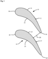
- FIG. 1 Two turbine blades 10 and 10 'arranged in the circumferential direction UR of a turbine stage are shown as an example.
- the turbine blades can be part of a guide blade ring and designed as guide blades 10, 10 '.
- the guide vanes 10, 10 ' are in the Fig. 1 and also shown in the following figures as simplified schematic cross sections.
- Both guide vanes 10, 10' have a flow contour 12, 12', with a pressure side 14, 14' and a suction side 16, 16'.
- the pressure sides 14, 14' and the corresponding suction sides 16, 16' are each connected to one another by a front edge 18, 18' and a rear edge 20, 20'.
- the so-called A4 cross-section is formed between all adjacent guide blades.
- This A4 cross section can also be referred to as the distance between two adjacent guide vanes 10, 10 ', which in one specific area is measured.
- the A4 cross-section QS is measured between the pressure side 14 of the guide vane 10 and the suction side 16 'of the guide vane 10'.
- the A4 cross-sectional line QS extends from a rear area of the guide blades 10, approximately in the area of the rear edge 20, to a central area of the suction side 16 'of the guide blade 10'.
- This A4 cross-section represents an important variable for the flow conditions prevailing in the turbine stage. Deviations from this A4 cross-section lead to changed flow conditions and can negatively influence the efficiency of the gas turbine.
- FIG. 1 Two guide vanes 10, 10' are shown with the crossed hatching, the flow contour 12, 12' of which is shown in an original state. You can also say that the two guide vanes 10, 10 'are as good as new.
- the A4 cross-section QS or the corresponding distance between the two guide vanes is also of an original size due to the newness of the guide vanes 10, 10 ', so that optimal operation is possible.
- the guide vane 10 or all guide vanes of a turbine stage is initially provided. Depending on the design of a turbine stage, the guide vanes can be provided individually, or several guide vanes can be part of one Be guide vane segment, which has a plurality of guide vanes, in particular integrally connected to one another.
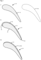
- An actual geometry of the worn guide vane 10, which is in Fig. 3 shown at the top left is first detected using a non-contact method, in particular an optical method (I). Methods such as non-contact 3D scanners or similar can be used here.
- This actual geometry which is represented in the present application by the flow contour 12, is compared with a target geometry.
- the target geometry SG is in Fig. 3 simplified and schematically indicated at the top right as a dotted flow contour. From the comparison between the actual geometry and the target geometry SG, target geometries can be calculated using optimization parameters that bring the flow contour in the area of the A4 cross-section as close as possible to the target geometry.
- material 22 is applied to the guide vane 10.
- an application of material 22 from the front edge 18 to the rear edge 20 along the suction side 16 is shown.
- material 22 can also be applied to the print side 14 if necessary, even if this is not explicitly described in the present example.
- the application of material 22 is carried out in particular by soldering or welding, preferably by diffusion soldering, in order to ensure an optimal connection between the application material 22 and the guide vane 10 to be repaired.
- the application of material 22 can be done manually and/or automatically.
- the quantity and/or the positions along the guide vane or the flow contour 12 can be determined, for example, based on the optimization parameters that were previously determined based on the comparison of the actual geometry and the target geometry.
- the flow contour 12 (target geometry ZG) of the guide vane 10 to be repaired is restored by automatically removing excess material 22 (see III).
- the guide vane 10 is brought into a reference position relative to a processing unit.
- the processing unit is set up to carry out an exact removal of material 22 based on the optimization parameters or data about the target geometry to be achieved.
- the removal of material 22 is preferably carried out by grinding or milling.
- the guide vane 10 has a Flow contour 12, which essentially corresponds to the desired geometry again, the guide vane 10 containing a part made of original material and a part made of additionally applied material 22.
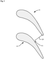
- FIG. 4 If one looks at two adjacent repaired guide vanes 10, 10 'after such a largely automated repair process, as shown in Fig. 4 is shown, it can be seen that the A4 cross-section QS essentially corresponds to the original A4 cross-section QS and the original flow contour ( Fig. 1 ) corresponds. Thus, the increase VG of the flow cross section ( Fig. 2 ) by applying material 22 in the corresponding areas of the guide blades 10, 10 ', so that optimal operation of the gas turbine is possible again with the repaired guide blades 10, 10'.
- the method presented here can, for example, be carried out at various stations in a maintenance workshop.
- at least one computer unit is preferably used that is set up for this purpose is to control corresponding detection devices or tool devices, in particular on the basis of the recorded or calculated data on the target geometry.
- Data representing the target geometry of a guide vane can be recorded, for example, by detecting the geometry of a new guide vane from the outside using appropriate detection devices, for example by non-contact 3D scanning, in particular optical detection methods.
- the target geometry data can also be derived from design data that is available for a specific guide vane type and which forms the basis for producing a new guide vane.
Landscapes
- Engineering & Computer Science (AREA)
- Mechanical Engineering (AREA)
- General Engineering & Computer Science (AREA)
- Physics & Mathematics (AREA)
- Fluid Mechanics (AREA)
- Turbine Rotor Nozzle Sealing (AREA)
Claims (12)
- Procédé de réparation pour des aubes directrices (10, 10') d'une turbine à gaz, en particulier d'une turbine à gaz d'aéronef, comprenant les étapes suivantes :fourniture d'au moins une aube directrice (10, 10') à entretenir ;détection de la géométrie réelle de l'aube directrice (10, 10') à entretenir à l'aide d'au moins un procédé de mesure sans contact ;comparaison de la géométrie réelle de l'aube directrice (10, 10') détectée par le procédé de mesure sans contact avec une géométrie de consigne (SG) prédéterminée pour un type d'aube directrice correspondant ;calcul d'une géométrie cible (ZG) pour l'aube directrice (10, 10') à entretenir, laquelle géométrie cible correspond autant que possible à la géométrie de consigne (SG), de telle sorte que, à l'aide de paramètres d'optimisation, la géométrie de consigne (SG) de l'aube directrice (10, 10') à entretenir est rapprochée au moins dans certaines sections le long de son contour d'écoulement ;application de matériau le long d'un extrados (16, 16') du contour d'écoulement de l'aube directrice (10, 10') depuis un bord d'attaque (18, 18') jusqu'à un bord de fuite (20, 20') de l'aube directrice (10, 10') à entretenir et enlèvement par machine de matériau (22) appliqué le long d'un extrados (16, 16') du contour d'écoulement de l'aube directrice (10, 10') depuis un bord d'attaque (18, 18') jusqu'à un bord de fuite (20, 20') de l'aube directrice (10, 10') à entretenir, de telle sorte que la géométrie cible (ZG) calculée est produite, caractérisé en ce quela géométrie cible (ZG) de l'aube directrice (10, 10') à entretenir est calculée et reproduite de sorte que le contour d'écoulement dans la zone de la section transversale A4 (QS) de l'aube directrice (10, 10') à entretenir est rapproché le plus possible du contour d'écoulement de la géométrie de consigne (SG) dans la zone de la section transversale A4, dans lequel la section transversale A4 (QS) est définie com me la distance entre deux aubes directrices (10, 10') adjacentes qui s'étend entre une zone centrale de l'extrados (16') de l'aube directrice (10') à entretenir et une zone du bord de fuite (20) de l'aube directrice (10) adjacente, eten ce que l'aube directrice (10, 10') fournie est prélevée du premier étage de turbine haute pression d'une turbine haute pression, lequel se raccorde directement à la chambre de combustion.
- Procédé de réparation selon la revendication, dans lequel l'enlèvement de matériau (22) est réalisé par fraisage ou/et meulage automatisés ou/et par un autre procédé d'usinage par enlèvement de copeaux automatisé.
- Procédé de réparation selon l'une des revendications précédentes, dans lequel l'application de matériau (22) est effectuée par brasage, en particulier par brasage par diffusion.
- Procédé de réparation selon l'une des revendications précédentes, dans lequel l'application de matériau (22) est réalisée en fonction de la géométrie réelle détectée et de la géométrie cible (ZG).
- Procédé de réparation selon l'une des revendications précédentes, dans lequel, après l'application de matériau (22) sur l'aube directrice (10, 10'), un autre mesurage est réalisé pour positionner l'aube directrice (10, 10') pour l'enlèvement du matériau (22).
- Procédé de réparation selon l'une des revendications précédentes, dans lequel la géométrie de consigne (SG) est un rapprochement d'une géométrie d'origine ou la géométrie d'origine de l'aube directrice.
- Procédé de réparation selon la revendication 6, dans lequel la géométrie de consigne (SG) est déterminée comme rapprochement de la géométrie d'origine par un procédé de mesure qui est réalisé sur une aube directrice à l'état neuf.
- Procédé de réparation selon la revendication 6, dans lequel la géométrie de consigne (SG) est dérivée com me géométrie d'origine à partir de données de construction d'une aube directrice ou la géométrie de consigne est définie sur la base d'un nouveau développement.
- Procédé de réparation selon l'une des revendications précédentes, dans lequel les étapes de procédé sont réalisées de manière répétée jusqu'à ce que toutes les aubes directrices (10, 10') d'une couronne d'aubes directrices d'un étage de turbine, en particulier d'un étage de turbine haute pression, soient réparées.
- Aube directrice comprenant au moins une zone de réparation, caractérisée en ce que ladite zone de réparation a été produite par le procédé de réparation selon l'une des revendications précédentes, dans laquelle l'aube directrice présente une géométrie cible (ZG) du contour d'écoulement dans la zone de la section transversale A4 (QS), laquelle géométrie cible est rapprochée le plus possible du contour d'écoulement de la géométrie de consigne (SG) dans la zone de la section transversale A4, dans laquelle la section transversale A4 (QS) est définie comme la distance entre deux aubes directrices (10, 10') adjacentes qui s'étend entre une zone centrale de l'extrados (16') de l'aube directrice (10') et une zone du bord de fuite (20) d'une aube directrice (10) adjacente, et en ce que l'aube directrice (10,10') est le premier étage de turbine haute pression d'une turbine haute pression, lequel se raccorde directement à la chambre de combustion d'une turbine à gaz d'aéronef.
- Couronne d'aubes directrices d'un premier étage de turbine haute pression d'une turbine haute pression, lequel se raccorde directement à la chambre de combustion d'une turbine à gaz d'aéronef, comportant plusieurs aubes directrices (10, 10') selon la revendication 10.
- Système de réparation pour l'entretien d'aubes directrices comprenantau moins un appareil de réception qui est conçu pour maintenir au moins une aube directrice (10, 10') à entretenir,au moins un dispositif de mesure qui est configuré pour détecter sans contact une géométrie réelle de l'aube directrice (10, 10') à entretenir ;au moins un dispositif de traitement automatique, dans lequel le dispositif de traitement comprend un appareil de fraisage ou un appareil de meulage ;au moins une unité informatique qui est configurée pourcommander le dispositif de mesure et le dispositif de traitement,mémoriser dans une mémoire associée une géométrie de consigne (SG) d'un type d'aube directrice correspondant,calculer une géométrie cible (ZG) sur la base de paramètres d'optimisation et sur la base de la comparaison de la géométrie réelle et de la géométrie de consigne (SG), caractérisé en ce que le dispositif de traitement automatique est conçu pour appliquer du matériau (22) le long d'un extrados (16, 16') du contour d'écoulement de l'aube directrice (10, 10') à entretenir depuis un bord d'attaque (18, 18') jusqu'à un bord de fuite (20, 20') et pour enlever du matériau (22) appliqué depuis un bord d'attaque (18, 18') jusqu'à un bord de fuite (20, 20'), en ce quecommander le dispositif de traitement de telle sorte que la géométrie cible (ZG) de l'aube directrice (10, 10') à entretenir est reproduite de sorte que le contour d'écoulement dans la zone de la section transversale A4 (QS) de l'aube directrice (10, 10') à entretenir est rapproché le plus possible du contour d'écoulement de la géométrie de consigne (SG) dans la zone de la section transversale A4, dans lequel la section transversale A4 (QS) est définie comme la distance entre deux aubes directrices (10, 10') adjacentes qui s'étend entre une zone centrale de l'extrados (16') de l'aube directrice (10') à entretenir et une zone du bord de fuite (20) de l'aube directrice (10) adjacente, et en ce que l'aube directrice (10,10') est le premier étage de turbine haute pression d'une turbine haute pression, lequel se raccorde directement à la chambre de combustion d'une turbine à gaz d'aéronef.
Applications Claiming Priority (1)
| Application Number | Priority Date | Filing Date | Title |
|---|---|---|---|
| DE102016201764.0A DE102016201764A1 (de) | 2016-02-05 | 2016-02-05 | Reparaturverfahren für Turbinenschaufeln |
Publications (2)
| Publication Number | Publication Date |
|---|---|
| EP3202529A1 EP3202529A1 (fr) | 2017-08-09 |
| EP3202529B1 true EP3202529B1 (fr) | 2023-11-22 |
Family
ID=57681278
Family Applications (1)
| Application Number | Title | Priority Date | Filing Date |
|---|---|---|---|
| EP16204238.6A Active EP3202529B1 (fr) | 2016-02-05 | 2016-12-15 | Procédé de réparation d'aubes statoriques de turbine, aube statorique de turbine reparée et système de réparation d'aubes statoriques de turbine |
Country Status (3)
| Country | Link |
|---|---|
| US (1) | US20170226860A1 (fr) |
| EP (1) | EP3202529B1 (fr) |
| DE (1) | DE102016201764A1 (fr) |
Families Citing this family (10)
| Publication number | Priority date | Publication date | Assignee | Title |
|---|---|---|---|---|
| AT521096A1 (de) * | 2018-04-13 | 2019-10-15 | Alpine Metal Tech Gmbh | Verfahren zur Erstellung von 3D-Bearbeitungsdaten einer Kfz-Felge |
| CN108844459B (zh) * | 2018-05-03 | 2020-07-03 | 华中科技大学无锡研究院 | 一种叶片数字化样板检测系统的标定方法及装置 |
| WO2020027928A2 (fr) * | 2018-06-22 | 2020-02-06 | United Technologies Corporation | Systèmes et procédés de fabrication adaptative automatisée de moulages de surface portante |
| US12162627B2 (en) | 2019-04-05 | 2024-12-10 | Rtx Corporation | Aircraft component repair system and process |
| GB201913379D0 (en) * | 2019-09-17 | 2019-10-30 | Rolls Royce Plc | A gas turbine engine |
| CN111023992B (zh) * | 2019-12-25 | 2020-07-31 | 四川大学 | 基于线结构光的截面曲线特征检测方法及其应用 |
| GB202110465D0 (en) * | 2021-07-21 | 2021-09-01 | Rolls Royce Plc | Aerofoil shaping method |
| US12358232B2 (en) * | 2022-09-09 | 2025-07-15 | Pratt & Whitney Canada Corp. | Adaptive manufacturing using structured light data |
| US20240082939A1 (en) * | 2022-09-09 | 2024-03-14 | Pratt & Whitney Canada Corp. | Adaptively depositing braze material using structured light scan data |
| US12115598B2 (en) | 2023-03-02 | 2024-10-15 | Pratt & Whitney Canada Corp. | Adaptive overhaul using plural scanning methods |
Citations (1)
| Publication number | Priority date | Publication date | Assignee | Title |
|---|---|---|---|---|
| US20070251072A1 (en) * | 2006-04-28 | 2007-11-01 | Honeywell International, Inc. | Adaptive machining and weld repair process |
Family Cites Families (11)
| Publication number | Priority date | Publication date | Assignee | Title |
|---|---|---|---|---|
| US5285572A (en) * | 1992-08-12 | 1994-02-15 | General Electric Company | Method and system for machining contoured parts |
| DE19922012C1 (de) * | 1999-05-12 | 2000-10-19 | Mtu Muenchen Gmbh | Verfahren zur Fertigung angepaßter, strömungstechnischer Oberflächen |
| DE10055505C2 (de) * | 2000-11-10 | 2003-03-20 | Mtu Aero Engines Gmbh | Verfahren zur Instandsetzung von Schaufeln |
| DE10065406A1 (de) * | 2000-12-27 | 2002-07-04 | Alstom Switzerland Ltd | Verfahren zum Reparieren von Schadstellen an einem Metallbauteil |
| US20020128790A1 (en) * | 2001-03-09 | 2002-09-12 | Donald Woodmansee | System and method of automated part evaluation including inspection, disposition recommendation and refurbishment process determination |
| US6789315B2 (en) * | 2002-03-21 | 2004-09-14 | General Electric Company | Establishing a throat area of a gas turbine nozzle, and a technique for modifying the nozzle vanes |
| US7186070B2 (en) * | 2004-10-12 | 2007-03-06 | Honeywell International, Inc. | Method for modifying gas turbine nozzle area |
| EP1790745A1 (fr) * | 2005-11-28 | 2007-05-30 | Siemens Aktiengesellschaft | Procédé de réparation de fissures dans des éléments structurels et alliage de brasage pour le brazage des éléments structurels |
| US7731809B2 (en) * | 2006-01-18 | 2010-06-08 | Honeywell International Inc. | Activated diffusion brazing alloys and repair process |
| US20090313823A1 (en) * | 2008-06-24 | 2009-12-24 | Todd Jay Rockstroh | Imparting deep compressive residual stresses into a gas turbine engine airfoil peripheral repair weldment |
| US9121282B2 (en) * | 2012-02-02 | 2015-09-01 | Honeywell International Inc. | Methods for the controlled reduction of turbine nozzle flow areas and turbine nozzle components having reduced flow areas |
-
2016
- 2016-02-05 DE DE102016201764.0A patent/DE102016201764A1/de active Pending
- 2016-12-15 EP EP16204238.6A patent/EP3202529B1/fr active Active
-
2017
- 2017-01-30 US US15/419,199 patent/US20170226860A1/en active Pending
Patent Citations (1)
| Publication number | Priority date | Publication date | Assignee | Title |
|---|---|---|---|---|
| US20070251072A1 (en) * | 2006-04-28 | 2007-11-01 | Honeywell International, Inc. | Adaptive machining and weld repair process |
Also Published As
| Publication number | Publication date |
|---|---|
| EP3202529A1 (fr) | 2017-08-09 |
| US20170226860A1 (en) | 2017-08-10 |
| DE102016201764A1 (de) | 2017-08-10 |
Similar Documents
| Publication | Publication Date | Title |
|---|---|---|
| EP3202529B1 (fr) | Procédé de réparation d'aubes statoriques de turbine, aube statorique de turbine reparée et système de réparation d'aubes statoriques de turbine | |
| DE19642980C1 (de) | Verfahren zur Instandsetzung verschlissener Schaufelspitzen von Verdichter- und Turbinenschaufel | |
| EP2925486B1 (fr) | Procédé et dispositif de réparation d'un élément structural d'aéronef et/ou de turbine à gaz | |
| EP1207004B1 (fr) | Procédé de réparation d' aubes | |
| DE60103786T2 (de) | Bearbeitung mit Verschiebung der nominellen Positionsbestimmungen | |
| CH704448A1 (de) | Verfahren zum Reparieren bzw. Rekonditionieren eines stark beschädigten Bauteils, insbesondere aus dem Heissgasbereich einer Gasturbine. | |
| EP2655005B1 (fr) | Procédé de réparation de composants d'une turbine à gaz | |
| WO2008046387A1 (fr) | Pales de turbines à haute pression et procédé de réparation de pales de turbines à haute pression | |
| DE10316966A1 (de) | Verfahren zum Wiederaufbauen flächig ausgebildeter beschädigter Bauteile | |
| EP2008756A1 (fr) | Procédé et dispositif de réparation de rotors monoblocs (BLISK) de turbines à gaz | |
| EP3285961A1 (fr) | Procédé et dispositif d'usinage d'un outil par enlèvement de matière | |
| DE102008037521A1 (de) | Z-Nutgestalt für eine Turbinenschaufel | |
| EP2715322A1 (fr) | Procédé et dispositif pour le contrôle des fissures d'une pièce structurale d'avion ou de turbine à gaz | |
| EP3211550A1 (fr) | Procédé de fabrication d'un modèle cao 3d, utilisation d'un modèle cao 3d, produit-programme d'ordinateur et système d'usinage à commande numérique | |
| EP2876183A2 (fr) | Procédé et dispositif d'application automatique d'un revêtement par pulvérisation | |
| EP4058271A1 (fr) | Appareil et procédé permettant de fabriquer un article moulé tridimensionnel | |
| WO2008131724A1 (fr) | Semi-produit permettant de réparer une aube pour une turbine à gaz et procédé de réparation d'une aube pour une turbine à gaz | |
| EP3512661A1 (fr) | Procédé de fabrication additive avec marquage d'une plateforme de construction au moyen de points de référence | |
| DE102011102286A1 (de) | Verfahren und Anordnung zur Bearbeitung von Gasturbinenschaufeln | |
| DE102007019951A1 (de) | Reparaturverfahren für die Reparatur von Integralrotoren einer Gasturbine | |
| EP1716315A2 (fr) | Procede de fabrication de surfaces relevant de la technique des fluides, adaptees | |
| EP2707576B1 (fr) | Vérification du contour d'une aube de turbomachine | |
| EP3176560B1 (fr) | Procede de test une aube de turbine | |
| EP3507659B1 (fr) | Procédé de fabrication de pales d'une machine interagissant avec un fluide | |
| DE10319020A1 (de) | Verfahren und Vorrichtung zum Verrunden von Kanten an Bauteilen |
Legal Events
| Date | Code | Title | Description |
|---|---|---|---|
| PUAI | Public reference made under article 153(3) epc to a published international application that has entered the european phase |
Free format text: ORIGINAL CODE: 0009012 |
|
| STAA | Information on the status of an ep patent application or granted ep patent |
Free format text: STATUS: THE APPLICATION HAS BEEN PUBLISHED |
|
| AK | Designated contracting states |
Kind code of ref document: A1 Designated state(s): AL AT BE BG CH CY CZ DE DK EE ES FI FR GB GR HR HU IE IS IT LI LT LU LV MC MK MT NL NO PL PT RO RS SE SI SK SM TR |
|
| AX | Request for extension of the european patent |
Extension state: BA ME |
|
| STAA | Information on the status of an ep patent application or granted ep patent |
Free format text: STATUS: REQUEST FOR EXAMINATION WAS MADE |
|
| 17P | Request for examination filed |
Effective date: 20180205 |
|
| RBV | Designated contracting states (corrected) |
Designated state(s): AL AT BE BG CH CY CZ DE DK EE ES FI FR GB GR HR HU IE IS IT LI LT LU LV MC MK MT NL NO PL PT RO RS SE SI SK SM TR |
|
| STAA | Information on the status of an ep patent application or granted ep patent |
Free format text: STATUS: EXAMINATION IS IN PROGRESS |
|
| 17Q | First examination report despatched |
Effective date: 20200924 |
|
| REG | Reference to a national code |
Ref country code: DE Ref legal event code: R079 Free format text: PREVIOUS MAIN CLASS: B23P0006000000 Ipc: B23K0020020000 Ref country code: DE Ref legal event code: R079 Ref document number: 502016016230 Country of ref document: DE Free format text: PREVIOUS MAIN CLASS: B23P0006000000 Ipc: B23K0020020000 |
|
| GRAP | Despatch of communication of intention to grant a patent |
Free format text: ORIGINAL CODE: EPIDOSNIGR1 |
|
| STAA | Information on the status of an ep patent application or granted ep patent |
Free format text: STATUS: GRANT OF PATENT IS INTENDED |
|
| RIC1 | Information provided on ipc code assigned before grant |
Ipc: F01D 5/14 20060101ALN20230619BHEP Ipc: G01B 11/28 20060101ALN20230619BHEP Ipc: B23K 1/00 20060101ALN20230619BHEP Ipc: B23K 31/02 20060101ALI20230619BHEP Ipc: F01D 9/04 20060101ALI20230619BHEP Ipc: B23K 20/233 20060101ALI20230619BHEP Ipc: F01D 5/00 20060101ALI20230619BHEP Ipc: B23P 6/00 20060101ALI20230619BHEP Ipc: B23K 20/02 20060101AFI20230619BHEP |
|
| INTG | Intention to grant announced |
Effective date: 20230704 |
|
| GRAS | Grant fee paid |
Free format text: ORIGINAL CODE: EPIDOSNIGR3 |
|
| GRAA | (expected) grant |
Free format text: ORIGINAL CODE: 0009210 |
|
| STAA | Information on the status of an ep patent application or granted ep patent |
Free format text: STATUS: THE PATENT HAS BEEN GRANTED |
|
| AK | Designated contracting states |
Kind code of ref document: B1 Designated state(s): AL AT BE BG CH CY CZ DE DK EE ES FI FR GB GR HR HU IE IS IT LI LT LU LV MC MK MT NL NO PL PT RO RS SE SI SK SM TR |
|
| REG | Reference to a national code |
Ref country code: GB Ref legal event code: FG4D Free format text: NOT ENGLISH |
|
| REG | Reference to a national code |
Ref country code: CH Ref legal event code: EP |
|
| REG | Reference to a national code |
Ref country code: DE Ref legal event code: R096 Ref document number: 502016016230 Country of ref document: DE |
|
| REG | Reference to a national code |
Ref country code: IE Ref legal event code: FG4D Free format text: LANGUAGE OF EP DOCUMENT: GERMAN |
|
| REG | Reference to a national code |
Ref country code: LT Ref legal event code: MG9D |
|
| REG | Reference to a national code |
Ref country code: NL Ref legal event code: MP Effective date: 20231122 |
|
| PG25 | Lapsed in a contracting state [announced via postgrant information from national office to epo] |
Ref country code: GR Free format text: LAPSE BECAUSE OF FAILURE TO SUBMIT A TRANSLATION OF THE DESCRIPTION OR TO PAY THE FEE WITHIN THE PRESCRIBED TIME-LIMIT Effective date: 20240223 |
|
| PG25 | Lapsed in a contracting state [announced via postgrant information from national office to epo] |
Ref country code: IS Free format text: LAPSE BECAUSE OF FAILURE TO SUBMIT A TRANSLATION OF THE DESCRIPTION OR TO PAY THE FEE WITHIN THE PRESCRIBED TIME-LIMIT Effective date: 20240322 |
|
| PG25 | Lapsed in a contracting state [announced via postgrant information from national office to epo] |
Ref country code: LT Free format text: LAPSE BECAUSE OF FAILURE TO SUBMIT A TRANSLATION OF THE DESCRIPTION OR TO PAY THE FEE WITHIN THE PRESCRIBED TIME-LIMIT Effective date: 20231122 |
|
| PG25 | Lapsed in a contracting state [announced via postgrant information from national office to epo] |
Ref country code: NL Free format text: LAPSE BECAUSE OF FAILURE TO SUBMIT A TRANSLATION OF THE DESCRIPTION OR TO PAY THE FEE WITHIN THE PRESCRIBED TIME-LIMIT Effective date: 20231122 |
|
| PG25 | Lapsed in a contracting state [announced via postgrant information from national office to epo] |
Ref country code: ES Free format text: LAPSE BECAUSE OF FAILURE TO SUBMIT A TRANSLATION OF THE DESCRIPTION OR TO PAY THE FEE WITHIN THE PRESCRIBED TIME-LIMIT Effective date: 20231122 |
|
| PG25 | Lapsed in a contracting state [announced via postgrant information from national office to epo] |
Ref country code: NL Free format text: LAPSE BECAUSE OF FAILURE TO SUBMIT A TRANSLATION OF THE DESCRIPTION OR TO PAY THE FEE WITHIN THE PRESCRIBED TIME-LIMIT Effective date: 20231122 Ref country code: LT Free format text: LAPSE BECAUSE OF FAILURE TO SUBMIT A TRANSLATION OF THE DESCRIPTION OR TO PAY THE FEE WITHIN THE PRESCRIBED TIME-LIMIT Effective date: 20231122 Ref country code: IS Free format text: LAPSE BECAUSE OF FAILURE TO SUBMIT A TRANSLATION OF THE DESCRIPTION OR TO PAY THE FEE WITHIN THE PRESCRIBED TIME-LIMIT Effective date: 20240322 Ref country code: GR Free format text: LAPSE BECAUSE OF FAILURE TO SUBMIT A TRANSLATION OF THE DESCRIPTION OR TO PAY THE FEE WITHIN THE PRESCRIBED TIME-LIMIT Effective date: 20240223 Ref country code: ES Free format text: LAPSE BECAUSE OF FAILURE TO SUBMIT A TRANSLATION OF THE DESCRIPTION OR TO PAY THE FEE WITHIN THE PRESCRIBED TIME-LIMIT Effective date: 20231122 Ref country code: BG Free format text: LAPSE BECAUSE OF FAILURE TO SUBMIT A TRANSLATION OF THE DESCRIPTION OR TO PAY THE FEE WITHIN THE PRESCRIBED TIME-LIMIT Effective date: 20240222 Ref country code: PT Free format text: LAPSE BECAUSE OF FAILURE TO SUBMIT A TRANSLATION OF THE DESCRIPTION OR TO PAY THE FEE WITHIN THE PRESCRIBED TIME-LIMIT Effective date: 20240322 |
|
| PG25 | Lapsed in a contracting state [announced via postgrant information from national office to epo] |
Ref country code: SE Free format text: LAPSE BECAUSE OF FAILURE TO SUBMIT A TRANSLATION OF THE DESCRIPTION OR TO PAY THE FEE WITHIN THE PRESCRIBED TIME-LIMIT Effective date: 20231122 Ref country code: RS Free format text: LAPSE BECAUSE OF FAILURE TO SUBMIT A TRANSLATION OF THE DESCRIPTION OR TO PAY THE FEE WITHIN THE PRESCRIBED TIME-LIMIT Effective date: 20231122 Ref country code: PL Free format text: LAPSE BECAUSE OF FAILURE TO SUBMIT A TRANSLATION OF THE DESCRIPTION OR TO PAY THE FEE WITHIN THE PRESCRIBED TIME-LIMIT Effective date: 20231122 Ref country code: NO Free format text: LAPSE BECAUSE OF FAILURE TO SUBMIT A TRANSLATION OF THE DESCRIPTION OR TO PAY THE FEE WITHIN THE PRESCRIBED TIME-LIMIT Effective date: 20240222 Ref country code: LV Free format text: LAPSE BECAUSE OF FAILURE TO SUBMIT A TRANSLATION OF THE DESCRIPTION OR TO PAY THE FEE WITHIN THE PRESCRIBED TIME-LIMIT Effective date: 20231122 Ref country code: HR Free format text: LAPSE BECAUSE OF FAILURE TO SUBMIT A TRANSLATION OF THE DESCRIPTION OR TO PAY THE FEE WITHIN THE PRESCRIBED TIME-LIMIT Effective date: 20231122 |
|
| PG25 | Lapsed in a contracting state [announced via postgrant information from national office to epo] |
Ref country code: DK Free format text: LAPSE BECAUSE OF FAILURE TO SUBMIT A TRANSLATION OF THE DESCRIPTION OR TO PAY THE FEE WITHIN THE PRESCRIBED TIME-LIMIT Effective date: 20231122 |
|
| PG25 | Lapsed in a contracting state [announced via postgrant information from national office to epo] |
Ref country code: CZ Free format text: LAPSE BECAUSE OF FAILURE TO SUBMIT A TRANSLATION OF THE DESCRIPTION OR TO PAY THE FEE WITHIN THE PRESCRIBED TIME-LIMIT Effective date: 20231122 |
|
| PG25 | Lapsed in a contracting state [announced via postgrant information from national office to epo] |
Ref country code: SK Free format text: LAPSE BECAUSE OF FAILURE TO SUBMIT A TRANSLATION OF THE DESCRIPTION OR TO PAY THE FEE WITHIN THE PRESCRIBED TIME-LIMIT Effective date: 20231122 |
|
| PG25 | Lapsed in a contracting state [announced via postgrant information from national office to epo] |
Ref country code: SM Free format text: LAPSE BECAUSE OF FAILURE TO SUBMIT A TRANSLATION OF THE DESCRIPTION OR TO PAY THE FEE WITHIN THE PRESCRIBED TIME-LIMIT Effective date: 20231122 Ref country code: SK Free format text: LAPSE BECAUSE OF FAILURE TO SUBMIT A TRANSLATION OF THE DESCRIPTION OR TO PAY THE FEE WITHIN THE PRESCRIBED TIME-LIMIT Effective date: 20231122 Ref country code: RO Free format text: LAPSE BECAUSE OF FAILURE TO SUBMIT A TRANSLATION OF THE DESCRIPTION OR TO PAY THE FEE WITHIN THE PRESCRIBED TIME-LIMIT Effective date: 20231122 Ref country code: IT Free format text: LAPSE BECAUSE OF FAILURE TO SUBMIT A TRANSLATION OF THE DESCRIPTION OR TO PAY THE FEE WITHIN THE PRESCRIBED TIME-LIMIT Effective date: 20231122 Ref country code: EE Free format text: LAPSE BECAUSE OF FAILURE TO SUBMIT A TRANSLATION OF THE DESCRIPTION OR TO PAY THE FEE WITHIN THE PRESCRIBED TIME-LIMIT Effective date: 20231122 Ref country code: DK Free format text: LAPSE BECAUSE OF FAILURE TO SUBMIT A TRANSLATION OF THE DESCRIPTION OR TO PAY THE FEE WITHIN THE PRESCRIBED TIME-LIMIT Effective date: 20231122 Ref country code: CZ Free format text: LAPSE BECAUSE OF FAILURE TO SUBMIT A TRANSLATION OF THE DESCRIPTION OR TO PAY THE FEE WITHIN THE PRESCRIBED TIME-LIMIT Effective date: 20231122 |
|
| REG | Reference to a national code |
Ref country code: CH Ref legal event code: PL |
|
| PG25 | Lapsed in a contracting state [announced via postgrant information from national office to epo] |
Ref country code: LU Free format text: LAPSE BECAUSE OF NON-PAYMENT OF DUE FEES Effective date: 20231215 |
|
| REG | Reference to a national code |
Ref country code: DE Ref legal event code: R097 Ref document number: 502016016230 Country of ref document: DE |
|
| PG25 | Lapsed in a contracting state [announced via postgrant information from national office to epo] |
Ref country code: MC Free format text: LAPSE BECAUSE OF FAILURE TO SUBMIT A TRANSLATION OF THE DESCRIPTION OR TO PAY THE FEE WITHIN THE PRESCRIBED TIME-LIMIT Effective date: 20231122 |
|
| REG | Reference to a national code |
Ref country code: BE Ref legal event code: MM Effective date: 20231231 |
|
| PG25 | Lapsed in a contracting state [announced via postgrant information from national office to epo] |
Ref country code: MC Free format text: LAPSE BECAUSE OF FAILURE TO SUBMIT A TRANSLATION OF THE DESCRIPTION OR TO PAY THE FEE WITHIN THE PRESCRIBED TIME-LIMIT Effective date: 20231122 Ref country code: LU Free format text: LAPSE BECAUSE OF NON-PAYMENT OF DUE FEES Effective date: 20231215 |
|
| PLBE | No opposition filed within time limit |
Free format text: ORIGINAL CODE: 0009261 |
|
| STAA | Information on the status of an ep patent application or granted ep patent |
Free format text: STATUS: NO OPPOSITION FILED WITHIN TIME LIMIT |
|
| REG | Reference to a national code |
Ref country code: IE Ref legal event code: MM4A |
|
| PG25 | Lapsed in a contracting state [announced via postgrant information from national office to epo] |
Ref country code: IE Free format text: LAPSE BECAUSE OF NON-PAYMENT OF DUE FEES Effective date: 20231215 |
|
| PG25 | Lapsed in a contracting state [announced via postgrant information from national office to epo] |
Ref country code: BE Free format text: LAPSE BECAUSE OF NON-PAYMENT OF DUE FEES Effective date: 20231231 |
|
| PG25 | Lapsed in a contracting state [announced via postgrant information from national office to epo] |
Ref country code: CH Free format text: LAPSE BECAUSE OF NON-PAYMENT OF DUE FEES Effective date: 20231231 |
|
| PG25 | Lapsed in a contracting state [announced via postgrant information from national office to epo] |
Ref country code: SI Free format text: LAPSE BECAUSE OF FAILURE TO SUBMIT A TRANSLATION OF THE DESCRIPTION OR TO PAY THE FEE WITHIN THE PRESCRIBED TIME-LIMIT Effective date: 20231122 |
|
| 26N | No opposition filed |
Effective date: 20240823 |
|
| PG25 | Lapsed in a contracting state [announced via postgrant information from national office to epo] |
Ref country code: SI Free format text: LAPSE BECAUSE OF FAILURE TO SUBMIT A TRANSLATION OF THE DESCRIPTION OR TO PAY THE FEE WITHIN THE PRESCRIBED TIME-LIMIT Effective date: 20231122 Ref country code: IE Free format text: LAPSE BECAUSE OF NON-PAYMENT OF DUE FEES Effective date: 20231215 Ref country code: CH Free format text: LAPSE BECAUSE OF NON-PAYMENT OF DUE FEES Effective date: 20231231 Ref country code: BE Free format text: LAPSE BECAUSE OF NON-PAYMENT OF DUE FEES Effective date: 20231231 |
|
| REG | Reference to a national code |
Ref country code: AT Ref legal event code: MM01 Ref document number: 1633403 Country of ref document: AT Kind code of ref document: T Effective date: 20231215 |
|
| PG25 | Lapsed in a contracting state [announced via postgrant information from national office to epo] |
Ref country code: AT Free format text: LAPSE BECAUSE OF NON-PAYMENT OF DUE FEES Effective date: 20231215 |
|
| PG25 | Lapsed in a contracting state [announced via postgrant information from national office to epo] |
Ref country code: FI Free format text: LAPSE BECAUSE OF FAILURE TO SUBMIT A TRANSLATION OF THE DESCRIPTION OR TO PAY THE FEE WITHIN THE PRESCRIBED TIME-LIMIT Effective date: 20231122 |
|
| PG25 | Lapsed in a contracting state [announced via postgrant information from national office to epo] |
Ref country code: CY Free format text: LAPSE BECAUSE OF FAILURE TO SUBMIT A TRANSLATION OF THE DESCRIPTION OR TO PAY THE FEE WITHIN THE PRESCRIBED TIME-LIMIT; INVALID AB INITIO Effective date: 20161215 |
|
| PG25 | Lapsed in a contracting state [announced via postgrant information from national office to epo] |
Ref country code: HU Free format text: LAPSE BECAUSE OF FAILURE TO SUBMIT A TRANSLATION OF THE DESCRIPTION OR TO PAY THE FEE WITHIN THE PRESCRIBED TIME-LIMIT; INVALID AB INITIO Effective date: 20161215 |
|
| PG25 | Lapsed in a contracting state [announced via postgrant information from national office to epo] |
Ref country code: TR Free format text: LAPSE BECAUSE OF FAILURE TO SUBMIT A TRANSLATION OF THE DESCRIPTION OR TO PAY THE FEE WITHIN THE PRESCRIBED TIME-LIMIT Effective date: 20231122 |
|
| PGFP | Annual fee paid to national office [announced via postgrant information from national office to epo] |
Ref country code: GB Payment date: 20251218 Year of fee payment: 10 |
|
| PGFP | Annual fee paid to national office [announced via postgrant information from national office to epo] |
Ref country code: FR Payment date: 20251218 Year of fee payment: 10 |
|
| PGFP | Annual fee paid to national office [announced via postgrant information from national office to epo] |
Ref country code: DE Payment date: 20251222 Year of fee payment: 10 |