EP3202634A1 - Wagon de chemin de fer comportant des dispositifs de conditionnement d'air dans le poste de conduite, la cuisine et le compartiment passagers - Google Patents
Wagon de chemin de fer comportant des dispositifs de conditionnement d'air dans le poste de conduite, la cuisine et le compartiment passagers Download PDFInfo
- Publication number
- EP3202634A1 EP3202634A1 EP14903367.2A EP14903367A EP3202634A1 EP 3202634 A1 EP3202634 A1 EP 3202634A1 EP 14903367 A EP14903367 A EP 14903367A EP 3202634 A1 EP3202634 A1 EP 3202634A1
- Authority
- EP
- European Patent Office
- Prior art keywords
- cabin
- air
- galley
- air conditioner
- driver
- Prior art date
- Legal status (The legal status is an assumption and is not a legal conclusion. Google has not performed a legal analysis and makes no representation as to the accuracy of the status listed.)
- Granted
Links
Images



Classifications
-
- B—PERFORMING OPERATIONS; TRANSPORTING
- B61—RAILWAYS
- B61D—BODY DETAILS OR KINDS OF RAILWAY VEHICLES
- B61D27/00—Heating, cooling, ventilating, or air-conditioning
- B61D27/0018—Air-conditioning means, i.e. combining at least two of the following ways of treating or supplying air, namely heating, cooling or ventilating
-
- B—PERFORMING OPERATIONS; TRANSPORTING
- B61—RAILWAYS
- B61D—BODY DETAILS OR KINDS OF RAILWAY VEHICLES
- B61D27/00—Heating, cooling, ventilating, or air-conditioning
-
- Y—GENERAL TAGGING OF NEW TECHNOLOGICAL DEVELOPMENTS; GENERAL TAGGING OF CROSS-SECTIONAL TECHNOLOGIES SPANNING OVER SEVERAL SECTIONS OF THE IPC; TECHNICAL SUBJECTS COVERED BY FORMER USPC CROSS-REFERENCE ART COLLECTIONS [XRACs] AND DIGESTS
- Y02—TECHNOLOGIES OR APPLICATIONS FOR MITIGATION OR ADAPTATION AGAINST CLIMATE CHANGE
- Y02T—CLIMATE CHANGE MITIGATION TECHNOLOGIES RELATED TO TRANSPORTATION
- Y02T30/00—Transportation of goods or passengers via railways, e.g. energy recovery or reducing air resistance
Definitions
- the present invention relates to a railway vehicle having individual air conditioners in a driver's cabin, a galley and a passenger cabin.
- air conditioners are installed on a roof for keeping the temperature and humidity in the vehicle comfortable.
- air inside the vehicle of high temperature and high humidity is taken into the air conditioner to condition the temperature and humidity, and then returned to the inside of the vehicle, thereby maintaining comfortable environment inside the vehicle.
- increase of carbon dioxide and retention of odors in the vehicle are suppressed by ventilation in which part of air inside the vehicle taken into the air conditioner is discharged to the outside of the vehicle as well as fresh air is taken into the inside of the air conditioner from the outside of the vehicle.
- Patent Literature 1 discloses a technique for increasing redundancy with respect to the failure of the air conditioner by installing plural refrigerating cycles in one air conditioner as well as by installing two such air conditioners in one vehicle for suppressing deterioration of vehicle interior environment when the air conditioner fails.
- Patent Literature 1 JP-A-9-156355
- railway vehicles there exists a railway vehicle including a driver's cabin where a driver works, a galley for providing light meals and a passenger cabin for accommodating passengers, and three air conditioners for conditioning air in these respective cabins are individually installed in this vehicle.
- the air conditioner in the driver's cabin fails, it is desirable that conditioned air can be supplied to the driver's cabin from the air conditioner for the galley or the air conditioner for the passenger cabin.
- the galley where cooking devices such as a cooking stove are installed, odors tend to occur by cooking, and it is desirable to prevent these odors from being diffused to the driver's cabin and the passenger cabin.
- a fire occurs in the galley where cooking devices such as the cooking stove are installed or in the passenger cabin, since the railway vehicle have to be moved to a safe place and stop there, it is required to prevent smoke caused by the fire flowing into the driver's cabin.
- Patent Literature 1 Although a structure of an air-conditioning duct which does not impair comfortability of passengers when one air conditioner fails is described in Patent Literature 1, there is no consideration about suppression of diffusion of odors in the galley to the passenger cabin or the driver' s cabin and about suppression of intrusion of smoke caused by the fire occurring in the galley or the passenger cabin to the driver's cabin.
- an object of the invention is to provide a railway vehicle capable of suppressing diffusion of odors occurring in the galley into the passenger cabin or the driver's cabin which is adjacent thereto and suppressing intrusion of smoke caused by a fire occurring in the galley or the passenger cabin into the driver's cabin while maintaining comfortable environment in the vehicle and increasing the redundancy at the time of failure of the air conditioner.
- the invention it is possible to provide a railway vehicle capable of suppressing diffusion of odors in the galley to the driver's cabin or the passenger cabin which is adjacent thereto and suppressing intrusion of smoke caused by a fire occurring in the galley or the passenger cabin to the driver's cabin while maintaining comfortable vehicle environment and increasing the redundancy at the time of failure of the air conditioner.
- a width direction (sleeper direction) of the railway vehicle is denoted by 510
- a longitudinal direction of the railway vehicle is denoted by 520
- a height direction of the railway vehicle is denoted by 530.
- these directions may be occasionally abbreviated as the width direction 510, the longitudinal direction 520 and the height 530, respectively.
- Fig. 1 is a perspective view of a railway vehicle according to an embodiment of the invention.
- the railway vehicle 1 includes an underframe 11 forming a floor, side structure bodies 12 provided to stand on both ends of the underframe 11 in the width direction 520, a forefront structure body 15 and an end structure body 13 provided to stand on both ends of the underframe 11 in the longitudinal direction 520, and a roof structure body 14 placed on upper ends of the side structure bodies 12, the forehead structure body 15 and the end structure body 13 in the height direction 530.
- the structure bodies constituting the railway vehicle 1 are formed of a hollow extruded shape material made of aluminum alloy in which two face plates facing each other are connected by ribs for realizing both reduction of weight and improvement of productivity. Both ends of the underframe 11 in the longitudinal direction 520 constituting the railway vehicle 1 are supported by bogies having wheel axles rolling on an orbit.
- the side structure body 12 constituting the railway vehicle 1 windows 122 and a vestibule 124 serving as getting on and off of passengers are formed.
- the vestibule 124 is provided with a side sliding door along the longitudinal direction of the railway vehicle 1 so as to be opened and closed.
- a window 152 and a vestibule for crews 154 serving as getting on and off of crews are formed.
- Fig. 2 is a cross-sectional view of a cross section A of the railway vehicle of Fig. 1 seen from above
- Fig. 3 is a view showing B-B cross section of the railway vehicle of Fig. 2
- the interior of the railway vehicle 1 is partitioned (compartmentalized) into a driver's cabin, a front vestibule, a galley, a passenger cabin and a rear vestibule including a toilet in this order from a front position side by respective partition walls 114a to 114d, and doors through which crews and passengers can pass are provided in respective partition walls 114a to 114d.
- an air conditioner for the driver's cabin 2c On upper faces of the roof structure body 14 which covers the driver's cabin, the galley and the passenger cabin partitioned by respective partition walls 114a to 114e, an air conditioner for the driver's cabin 2c, an air conditioner for the galley 2a and an air conditioner for the passenger cabin 2b are individually provided (see Fig. 1 ).
- the air conditioner for the galley 2a and the air conditioner for the passenger cabin 2b each has a refrigerating cycle in which a refrigerant circulates, including a compressor, an indoor heat exchanger, an outdoor heat exchanger and so on, an outdoor blower provided in the outdoor heat exchanger, an indoor blower provided in the indoor heat exchanger, a heater (provided in the indoor heat exchanger) and exhaust blowers 29a (see Fig.
- the air conditioner for the galley 2a and the air conditioner for the passenger cabin 2b do not have an air supply blower, and fresh outdoor air (air supply) corresponding to an amount of air discharged to the outside of the vehicle is introduced into the air conditioners (vehicle) from air supply openings provided in both air conditioners by operations of the exhaust blowers 29a and 29b.
- the air conditioner for the driver's cabin 2c is provided with an air supply blower 28c (operation of which will be described later in Fig. 8 , though not shown) for taking fresh air of the outside of the vehicle into the air conditioner in addition to respective apparatuses installed in the air conditioner for the galley 2a and the like.
- the respective air conditioners 2a, 2b and 2c are provided with fresh air intake openings for taking vehicle outside air into the air conditioner and exhaust air discharge openings for exhausting air inside the vehicle to the outside of the vehicle.
- air supply valves 26a, 26b and 26c for opening/closing the intake openings (operation of which will be described in Fig. 8 ) are provided, and exhaust valves 27a, 27b an 27c (see Fig. 5 concerning the exhaust valve 27a) for opening/closing discharge openings of the exhaust air discharge openings are provided.
- the air supply valves and the exhaust valves provided together in the air conditioners are controlled to be closed when the railway vehicle enters the tunnel at high speed and to be opened when the railway vehicle leaves from the tunnel.
- a state where the railway vehicle is not ventilated for many hours continues and the environment in the vehicle is deteriorated.
- a timer is provided, which releases the air supply valves and the exhaust valves after a predetermined time (for example, five minutes) counted from the time when the air supply valves and the exhaust valves are closed passes, regardless of whether the railway vehicle leaves the tunnel.
- return ducts 34a, 34b and 34c for taking air inside the vehicle into respective air conditioners, conditioned air ducts 32a and 32c for blowing conditioned air temperature/humidity of which are conditioned in respective air conditioners to the passenger cabin and the like, and exhaust air ducts 36a and 36b for guiding air to the air conditioners, which is discharged from the inside of the vehicle to the outside of the vehicle.
- the front vestibule and the rear vestibule are sections where passengers and crews basically do not always stay, therefore, air conditioners corresponding to both these sections are not provided in the embodiment. Therefore, the conditioned air ducts and the exhaust air ducts are extended from air conditioners corresponding to the adjacent galley and the passenger cabin both the sections, and conditioned air is supplied and exhaust air is discharged through these ducts.
- the conditioned air duct 32a is arranged in a range from the driver's cabin to the rear vestibule through the front vestibule, the galley and the passenger cabin (a range extending over almost the entire length of the railway vehicle 1), and conditioned air is supplied to the conditioned air duct 32a from the air conditioner for the galley 2a and the air conditioner for the passenger cabin 2b.
- an opening/closing device 38b which blocks conditioned air flowing inside the conditioned air duct 32a is provided as shown in Fig. 6 as an enlarged view of a part "E" of Fig. 1 .
- an opening/closing device 38a is provided in the vicinity of a part above the partition wall 114c in the conditioned air duct 32a as shown in Fig. 2 .
- the vicinity of the part above the partition wall 114a as the installation position of the opening/closing device 38b is preferably the conditioned air duct 32a in a range including the driver's cabin to the front vestibule extending along the longitudinal direction 520 with the partition wall 114a interposed therebetween.
- the vicinity of the part where the opening/closing device 38a penetrates the partition wall 114c is preferably the vicinity of the partition wall 114c in a range from the galley to the passenger cabin.
- return ducts 34a and 34b for taking air in the galley into the air conditioner for the galley 2a are provided on the ceiling of the galley.
- the air inside the galley taken into the return ducts 34a and 34b moves along the longitudinal direction 520 inside the duct, then, taken into the inside of the air conditioner for the galley 2a from return openings provided on a bottom of the air conditioner for the galley 2a.
- the air taken into the air conditioner for the galley 2a is conditioned in temperature and humidity in a process of passing through an indoor heat exchanger 24 in summer and in a process of passing through a heater 25 in winder, then, the air is pressure fed to the conditioned air duct 32a by an indoor blower 22 and is supplied into the galley as the conditioned air.
- the return duct 34c for taking air in the driver's cabin into the air conditioner for the driver's cabin 2c (see Fig. 1 ) and the conditioned air duct 32c for supplying the conditioned air the temperature and humidity of which are adjusted to respective parts of the driver's cabin are provided as shown in Fig. 6 .
- the air inside the driver's cabin passes from a return opening 39b provided on the ceiling of the driver's cabin through the return duct 34c and is conditioned inside the air conditioner for the driver' s cabin 2c, then, passes through the conditioned air duct 32c and returns into the driver's cabin from an opening 39a for supplying the conditioned air.
- Cooking devices such as a cooking stove having a high heat load are installed in the galley, therefore, when exhaust heat generated by these devices is taken into the air conditioner for the galley 2a, an operation rate of the air conditioner for the galley 2a (specifically, an operation rate of a compressor forming the refrigerating cycle) is increased, and power consumption consumed by the air conditioner for the galley 2a is increased.
- the exhaust air duct 36a is arranged on the ceiling above the cooking devices such as the cooking stove having a high heat load provided in the galley as shown in Fig. 5 .
- exhaust air to be discharged to the outside of the vehicle from the toilet provided in the rear vestibule passes above the partition wall 114d from a ceiling of the toilet so as not to be mixed with return air to be taken into the air conditioner for the passenger cabin 2b and directly discharged to the outside of the vehicle via the exhaust air duct 36b connecting to the exhaust blower of the air conditioner for the passenger cabin 2b.
- the exhaust air from the toilet is not mixed with the return air to be taken into the air conditioner for the passenger cabin 2b, therefore, it is possible to suppress odors flowing into the passenger cabin and the galley adjacent to the passenger cabin.
- a smoke detection sensor 49a for detecting a fire occurring inside the railway vehicle is provided in a return air intake opening of the return duct 34a in the air conditioner for the galley 2a.
- a smoke detection sensor 49b is provided in a return air intake opening of the air conditioner for the passenger cabin 2b
- a smoke sensor 49c is provided on a ceiling of the front vestibule. In the case where these smoke detection sensors detect smoke, a detection signal of each smoke detection sensor is transmitted to a controller 116 (see Fig. 7 ).
- the controller 116 receiving the smoke detection signal opens/closes respective opening/closing devices provided in the conditioned air duct and closes the air supply valves and the exhaust valves provided in respective air conditioners, then, controls the exhaust blowers based on a predetermined operation mode at the time of occurrence of a fire.
- Fig. 4 is a view showing C-C cross section of the railway vehicle of Fig. 2 .
- the opening/closing device 38 for blocking the flow of conditioned air is provided inside the conditioned air duct 32a arranged in the part above the partition wall 114c as a partition between the galley and the passenger cabin. Normally, the opening/closing device 38a is blocked so as to suppress conditioned air conditioned in the air conditioner for the galley 2a and conditioned air conditioned in the air conditioner for the passenger cabin 2b to be mixed inside the conditioned air duct 32a. Furthermore, conditioned air conditioned in the air conditioner for the galley 2a is suppressed to be supplied to the passenger cabin via the conditioned air duct 32a, thereby preventing diffusion of odors.
- An operating portion 38b which penetrates a ceiling panel 44 so that opening/closing operation can be performed from the galley is provided in a lower part of the opening/closing device 38a.
- the opening/closing device 38a can be opened/closed by a crew operating the operation portion 38b.
- the operation portion 38b is operated according to need, for example, in the case where the air conditioner for the galley 2a fails or in the case where the air conditioner for the passenger cabin 2b fails, thereby introducing conditioned air conditioned in the air conditioner for the passenger cabin 2b or conditioned air conditioned in the air conditioner for the galley 2a to the passenger cabin to suppress deterioration of temperature environment in the galley or the passenger cabin.
- the opening/closing operation of the opening/closing device 38a is manually executed by a crew is shown, it is also possible to adopt a mechanism in which the opening/closing device 38a can be automatically opened/closed by electric power, an air pressure or a spring force based on a control signal from the controller 116.
- Fig. 5 is a view showing D-D cross section of the railway vehicle of Fig. 2 .
- the exhaust air duct 36a is provided over the ceilings of the driver's cabin, the front vestibule and the galley, and exhaust air from respective sections (compartments) passes through the exhaust air duct 36a and discharged to the outside of the vehicle by the exhaust blower 29a provided in the air conditioner for the galley 2a.
- the exhaust blower 29a On an upstream side of the exhaust blower 29a, an exit for exhaust air provided with the exhaust valve 27a is formed, and an opening for taking air outside the vehicle into the air conditioner and the air supply valve 26a (not shown) which can open/close the opening are provided in the vicinity of the indoor heat exchanger (see Fig. 3 ).
- the air supply valve 26a and the exhaust valve 27a are closed when the railway vehicle 1 enters the tunnel at a higher speed than the predetermined speed, thereby suppressing air inside the vehicle to be excessively discharged to the outside of the vehicle and suppressing air outside the vehicle (inside the tunnel) to be excessively taken into the vehicle due to variation of the pressure outside the vehicle received when the railway vehicle 1 passes through the tunnel at high speed, which prevents passengers, crews and others from feeling uncomfortable in sense of hearing.
- Fig. 6 is a view showing an enlarged part of a part "E" in the railway vehicle shown in Fig. 2 .
- One end of the conditioned air duct 32a which is arranged over almost the entire length of the railway vehicle 1 extends to the driver's cabin in a manner of penetrating above the partition wall 114a as a partition between the front vestibule and the driver's cabin, and an opening 39c which supplies conditioned air to the driver' s cabin is provided at an end (terminal portion) thereof.
- One end of the exhaust air duct 36a arranged from the galley to the front vestibule and driver's cabin extends to the driver's cabin in a manner of penetrating above the partition wall 114a as a partition between the front vestibule and the driver' s cabin, and an opening 39d which sucks exhaust air from the driver's cabin is provided at an end (terminal portion) thereof.
- the opening/closing device 38b which supplies and blocks conditioned air to the driver's cabin is provided in a portion penetrating the partition wall 114a in the conditioned air duct 32a and the exhaust air duct 36a.
- An opening/closing device 38c which sucks and blocks exhaust air from the driver's cabin with respect to the exhaust blower 27a is provided in a portion penetrating the partition wall 114a in the exhaust air duct 36a.
- the opening/closing device 38b is normally closed, however, when the air conditioner for the driver's cabin 2c fails, the opening/closing devices 38b and 38c are opened to thereby introduce conditioned air conditioned in the air conditioner for the galley 2a into the driver's cabin. It is also possible to discharge exhaust air from the driver's cabin to the outside of the vehicle by the exhaust blower 29a of the air conditioner for the galley 2a. Furthermore, when both the air conditioner for the driver's cabin 2c and the air conditioner for the galley 2a fail, air conditioned in the air conditioner for the passenger cabin 2b can be supplied to the driver's cabin by opening the above described opening/closing devices 38a and the opening/closing devices 38b.
- the smoke detection sensor provided in the galley operates while the air conditioner for the driver's cabin 2c fails and conditioned air is supplied to the driver's cabin from the air conditioner for the galley 2a, it is possible to suppress smoke and so on flowing into the driver' s cabin from the galley by closing the opening/closing devices 38b.
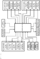
- Fig. 7 is a system diagram in which information inputted to the controller and target devices controlled by the controller are written.
- Fig. 7 shows only devices relating to the invention, and for example, the outdoor blower mounted on the air conditioner for the galley 2a and the like are not written.
- Information to be inputted to the controller 116 includes kilo-distance information indicating a position where the railway vehicle runs, smoke detection information issued by the smoke detection sensors 49a, 49b and 49c and failure information of the air conditioner for the galley 2a, the air conditioner for the passenger cabin 2b and the air conditioner for the driver's cabin 2c.
- the controller 116 can determines that the railway vehicle is running in a section not requiring vehicle interior lighting just before entering the tunnel, that the railway vehicle is passing through the tunnel section, that the railway vehicle is running in a section not requiring vehicle interior lighting after leaving the tunnel and other situations based on kilo-distance information and information of a running route inputted in advance before operation.
- Targets controlled by the controller 116 are a display device 118 displaying operation statuses of respective air conditioners and so on to crews and others, the air supply valves 26a, 26b and 26c, the exhaust valves 27a, 27b and 27c, the air supply blower 28c, the exhaust blowers 29a, 29b and 29c and the opening/closing devices 38b and 38c which are included in respective air conditioners 2a, 2b and 2c.
- the failure information or smoke detection information of respective air conditioners is inputted to the controller 116, the failure information or smoke detection information is displayed on the display device 118, therefore, crews are capable of checking a site, preparing for guiding passengers for evacuation and communicating with various related parties immediately after an event occurs.
- Fig. 8 is a chart showing examples of control rules for the air supply valves, the exhaust valves, the exhaust blowers and the opening/closing devices mounted on respective air conditioners.
- the air supply valves 26a, 26b and the exhaust valves 27a, 27b of the air conditioner for the galley 2a and the air conditioner for the passenger cabin 2b are opened, and fresh air (air supply) corresponding to exhaust air discharged from the inside of the vehicle (particularly, the galley and the passenger cabin) to the outside of the vehicle by the exhaust blowers 29a and 29b is taken into the air conditioners (the inside of the vehicle) from fresh air intake openings of these air conditioners to perform ventilation.
- the air supply valve 26c and the exhaust valve 29c are opened to thereby ventilate the driver's cabin by the exhaust blower 29c and the air supply blower 28c.
- the opening/closing devices 38a and 38b provided in the conditioned air duct 32a, and the opening/closing device 38c provided in the exhaust air duct 36 are closed, thereby preventing leakage of odors inside the galley to the driver's cabin and the passenger cabin via the conditioned air duct 32a.
- the air supply valves 26a, 26b and 26c and the exhaust valves 27a, 27b and 27c are closed just before the railway vehicle 1 runs into the tunnel based on tunnel position information and route information previously inputted before operation as described above, thereby suppressing variation of the pressure inside the vehicle caused by sudden change of the pressure inside the tunnel.
- a time after the air supply valves 26a, 26b and 26c and the exhaust valves 27a, 27b and 27c are closed is counted by a timer which is activated at the same time as respective valves are closed just before the railway vehicle 1 runs into the tunnel.
- the air supply valves 26a, 26b and 26c and the exhaust valves 27a, 27b and 27c are opened to perform ventilation again regardless of the position (even inside the tunnel) of the railway vehicle 1. According to the operation, it is possible to suppress increase in a concentration of a carbon dioxide gas (CO 2 ) or increase of odors inside the vehicle caused by extension of time during which ventilation is not performed such as the case of disruption of train schedules caused by a bad weather or the like, cases where the railway vehicle 1 stops inside the tunnel for many hours or goes slowly in a long tunnel or other cases.
- CO 2 carbon dioxide gas
- the opening/closing device 38a provided in the conditioned air duct 32a is opened to complement conditioned air (cooled or heated air) to each other.
- conditioned air cooled or heated air
- air inside the galley and air inside the passenger cabin circulate each other, therefore, there is a possibility that odors generated inside the galley leak to the passenger cabin.
- Priority is given to improvement of deterioration of temperature environment inside the vehicle due to the failure of the air conditioner while informing crews of limitation in using the cooking stove and so on if necessary.
- the opening/closing devices 38b and 38c are opened to supply conditioned air of the air conditioner for the galley 2a to the driver's cabin, thereby maintaining comfortability (temperature environment) inside the driver's cabin.
- the controller 116 closes the opening/closing devices 38b and 38c so that smoke generated in the galley, the passenger cabin, the front vestibule or the rear vestibule does not flow into the driver's cabin through the duct.
- the air supply valves 26a and 26b of the air conditioner for the galley 2a and the air conditioner for the passenger cabin 2b are closed and the exhaust valves 27a and 27b are opened, and operation of the exhaust blowers 29a and 29b are continued.
- exhaust air is discharged to the outside of the vehicle to thereby reduce air pressures in the galley and the passenger cabin in a state where fresh air is not taken from the outside of the vehicle into the galley or the passenger cabin as the origin of a fire, therefore, it is possible to suppress diffusion of smoke and so on to the driver's cabin or an adjacent vehicle from the galley or the passenger cabin where the fire occurs. Accordingly, passengers can be guided for evacuation from the emergently stopped vehicle to the outside of the vehicle or to another adjacent vehicle easily.
- the air supply valve 26c and the exhaust valve 27c of the air conditioner for the driver's cabin 2c are closed to suppress smoke discharged by the exhaust blowers 29a and 29b from the galley or the passenger cabin as the origin of the fire to the outside of the vehicle to be taken into the driver's cabin.
- the controller 116 follows the control rules giving top priority to the safety, therefore, in the case where the smoke detection sensor operates while the air conditioner for the driver's cabin 2c fails, the opened opening/closing devices 38b and 38c are closed when the air conditioner for the driver's cabin 2c fails, which can reduce the risk of smoke and so on caused by a fire flowing into the driver's cabin.
- the invention is not limited to the above embodiment and various modification examples are included.
- the above embodiment has been explained in detail for making the invention easily understood, and the invention is not limited to the embodiment having all explained components.
- Part of components in a certain embodiment can be replaced with components of another embodiment, and components of a certain embodiment can be added to components of another embodiment.
- components of other embodiments can be added, deleted and replaced with respect to part of components of each embodiment.
Landscapes
- Engineering & Computer Science (AREA)
- Mechanical Engineering (AREA)
- Air-Conditioning For Vehicles (AREA)
- Electric Propulsion And Braking For Vehicles (AREA)
Applications Claiming Priority (1)
| Application Number | Priority Date | Filing Date | Title |
|---|---|---|---|
| PCT/JP2014/076485 WO2016051580A1 (fr) | 2014-10-03 | 2014-10-03 | Wagon de chemin de fer comportant des dispositifs de conditionnement d'air dans le poste de conduite, la cuisine et le compartiment passagers |
Publications (3)
| Publication Number | Publication Date |
|---|---|
| EP3202634A1 true EP3202634A1 (fr) | 2017-08-09 |
| EP3202634A4 EP3202634A4 (fr) | 2018-06-13 |
| EP3202634B1 EP3202634B1 (fr) | 2019-08-21 |
Family
ID=55629666
Family Applications (1)
| Application Number | Title | Priority Date | Filing Date |
|---|---|---|---|
| EP14903367.2A Active EP3202634B1 (fr) | 2014-10-03 | 2014-10-03 | Voiture de chemin de fer comportant des dispositifs de conditionnement d'air dans le poste de conduite, la cuisine et le compartiment passagers |
Country Status (3)
| Country | Link |
|---|---|
| EP (1) | EP3202634B1 (fr) |
| JP (1) | JP6386576B2 (fr) |
| WO (1) | WO2016051580A1 (fr) |
Cited By (5)
| Publication number | Priority date | Publication date | Assignee | Title |
|---|---|---|---|---|
| WO2019127190A1 (fr) * | 2017-12-27 | 2019-07-04 | 中车长春轨道客车股份有限公司 | Rame de longs rails soudés et son conduit de climatiseur |
| CN109969212A (zh) * | 2017-12-27 | 2019-07-05 | 中车长春轨道客车股份有限公司 | 轨道列车及其空调风道 |
| DE102018201176A1 (de) | 2018-01-25 | 2019-07-25 | Siemens Aktiengesellschaft | Galley-Klimaanlage |
| WO2022127140A1 (fr) * | 2020-12-15 | 2022-06-23 | 中车株洲电力机车有限公司 | Véhicule de transport ferroviaire et procédé et système de commande de ventilation associés |
| US12091062B2 (en) | 2020-07-14 | 2024-09-17 | Hitachi, Ltd. | Railroad car |
Families Citing this family (3)
| Publication number | Priority date | Publication date | Assignee | Title |
|---|---|---|---|---|
| WO2018189769A1 (fr) * | 2017-04-10 | 2018-10-18 | 株式会社日立製作所 | Wagon de chemin de fer |
| CN108657205B (zh) * | 2018-05-08 | 2020-09-29 | 中车青岛四方机车车辆股份有限公司 | 车体结构及具有其的有轨列车 |
| CN112977512A (zh) * | 2019-12-17 | 2021-06-18 | 中车唐山机车车辆有限公司 | 轨道车辆的空调系统及轨道车辆 |
Family Cites Families (9)
| Publication number | Priority date | Publication date | Assignee | Title |
|---|---|---|---|---|
| US2367276A (en) * | 1943-07-16 | 1945-01-16 | B F Sturtevant Co | Air conditioning system for passenger vehicles |
| US2600889A (en) * | 1950-01-05 | 1952-06-17 | Vapor Heating Corp | Railway car temperature control system |
| JPS5657508A (en) * | 1979-10-11 | 1981-05-20 | Toshiba Corp | Air conditioning system for vehicle |
| JPS62172672U (fr) * | 1986-04-24 | 1987-11-02 | ||
| JP2732487B2 (ja) * | 1991-04-23 | 1998-03-30 | 川崎重工業株式会社 | 乗物の換気装置 |
| JPH09156356A (ja) * | 1995-12-08 | 1997-06-17 | Mitsubishi Electric Corp | 移動体用空気調和装置 |
| JP3328485B2 (ja) * | 1995-12-08 | 2002-09-24 | 三菱電機株式会社 | 移動体用空気調和装置 |
| CN102046405B (zh) * | 2008-05-30 | 2013-07-03 | 三菱电机株式会社 | 车辆用空调系统 |
| JP5924963B2 (ja) * | 2012-02-06 | 2016-05-25 | 三菱電機株式会社 | 車両用空調システム |
-
2014
- 2014-10-03 EP EP14903367.2A patent/EP3202634B1/fr active Active
- 2014-10-03 WO PCT/JP2014/076485 patent/WO2016051580A1/fr not_active Ceased
- 2014-10-03 JP JP2016551441A patent/JP6386576B2/ja active Active
Cited By (8)
| Publication number | Priority date | Publication date | Assignee | Title |
|---|---|---|---|---|
| WO2019127190A1 (fr) * | 2017-12-27 | 2019-07-04 | 中车长春轨道客车股份有限公司 | Rame de longs rails soudés et son conduit de climatiseur |
| CN109969212A (zh) * | 2017-12-27 | 2019-07-05 | 中车长春轨道客车股份有限公司 | 轨道列车及其空调风道 |
| CN109969212B (zh) * | 2017-12-27 | 2024-03-22 | 中车长春轨道客车股份有限公司 | 轨道列车及其空调风道 |
| DE102018201176A1 (de) | 2018-01-25 | 2019-07-25 | Siemens Aktiengesellschaft | Galley-Klimaanlage |
| WO2019145096A1 (fr) | 2018-01-25 | 2019-08-01 | Siemens Aktiengesellschaft | Climatiseur d'office |
| RU2770887C2 (ru) * | 2018-01-25 | 2022-04-25 | Сименс Мобилити Гмбх | Установка для кондиционирования воздуха в камбузе |
| US12091062B2 (en) | 2020-07-14 | 2024-09-17 | Hitachi, Ltd. | Railroad car |
| WO2022127140A1 (fr) * | 2020-12-15 | 2022-06-23 | 中车株洲电力机车有限公司 | Véhicule de transport ferroviaire et procédé et système de commande de ventilation associés |
Also Published As
| Publication number | Publication date |
|---|---|
| WO2016051580A1 (fr) | 2016-04-07 |
| EP3202634A4 (fr) | 2018-06-13 |
| JPWO2016051580A1 (ja) | 2017-06-22 |
| EP3202634B1 (fr) | 2019-08-21 |
| JP6386576B2 (ja) | 2018-09-05 |
Similar Documents
| Publication | Publication Date | Title |
|---|---|---|
| EP3202634B1 (fr) | Voiture de chemin de fer comportant des dispositifs de conditionnement d'air dans le poste de conduite, la cuisine et le compartiment passagers | |
| JP5127922B2 (ja) | 車両用空調システム | |
| JP5945328B2 (ja) | 車両編成の空調換気システムの制御方法 | |
| JP2012071680A (ja) | 給気装置と排気装置と排気送風機とを備える鉄道車両、および、鉄道車両に備えられる給気装置と排気装置と排気送風機の制御方法 | |
| CN113085486A (zh) | 车辆用集成式气帘系统及车辆 | |
| KR20190021666A (ko) | 고층건물의 제연장치 | |
| KR20110019925A (ko) | 이산화탄소 농도를 이용한 지하철 객실 냉방 제어 시스템 및 그 방법 | |
| RU134881U1 (ru) | Система подачи свежего воздуха в зависимости от количества пассажиров | |
| KR101194362B1 (ko) | 선박의 환기시스템 및 환기방법 | |
| JP4346429B2 (ja) | 車両用空気調和装置 | |
| JP2012116404A (ja) | 車両用気圧制御空調装置 | |
| JP2017089968A (ja) | 分煙空調システム | |
| KR101390764B1 (ko) | 철도 지하 정거장의 능동형여압시스템을 위한 다중 급배기 기능의 환기소 | |
| KR101728710B1 (ko) | 도시철도 승강장 스크린 도어 취부형 객실 외기유입 최소화 장치 및 그 방법 | |
| JP7531358B2 (ja) | 車両用空調装置 | |
| JP5058030B2 (ja) | 車両用空気調和装置及びそれを備えた鉄道車両 | |
| JP2001088699A (ja) | 鉄道車両用空気調和装置 | |
| WO2018189769A1 (fr) | Wagon de chemin de fer | |
| GB2567735B (en) | Control method for air conditioning and ventilation system for a train set in the event of a fire | |
| EP4183657B1 (fr) | Wagon de chemin de fer | |
| JP5214957B2 (ja) | 編成列車 | |
| JP2006008002A (ja) | 車両用空調装置 | |
| KR20090115244A (ko) | 자동차용 공기조화장치의 제어방법 | |
| RU134880U1 (ru) | Система регулировки состава воздуха на основе уровня содержания углекислого газа | |
| WO2024084564A1 (fr) | Système de climatisation pour véhicule ferroviaire |
Legal Events
| Date | Code | Title | Description |
|---|---|---|---|
| STAA | Information on the status of an ep patent application or granted ep patent |
Free format text: STATUS: THE INTERNATIONAL PUBLICATION HAS BEEN MADE |
|
| PUAI | Public reference made under article 153(3) epc to a published international application that has entered the european phase |
Free format text: ORIGINAL CODE: 0009012 |
|
| STAA | Information on the status of an ep patent application or granted ep patent |
Free format text: STATUS: REQUEST FOR EXAMINATION WAS MADE |
|
| 17P | Request for examination filed |
Effective date: 20170313 |
|
| AK | Designated contracting states |
Kind code of ref document: A1 Designated state(s): AL AT BE BG CH CY CZ DE DK EE ES FI FR GB GR HR HU IE IS IT LI LT LU LV MC MK MT NL NO PL PT RO RS SE SI SK SM TR |
|
| AX | Request for extension of the european patent |
Extension state: BA ME |
|
| DAX | Request for extension of the european patent (deleted) | ||
| A4 | Supplementary search report drawn up and despatched |
Effective date: 20180515 |
|
| RIC1 | Information provided on ipc code assigned before grant |
Ipc: B61D 27/00 20060101AFI20180508BHEP |
|
| GRAP | Despatch of communication of intention to grant a patent |
Free format text: ORIGINAL CODE: EPIDOSNIGR1 |
|
| STAA | Information on the status of an ep patent application or granted ep patent |
Free format text: STATUS: GRANT OF PATENT IS INTENDED |
|
| INTG | Intention to grant announced |
Effective date: 20190401 |
|
| GRAS | Grant fee paid |
Free format text: ORIGINAL CODE: EPIDOSNIGR3 |
|
| GRAA | (expected) grant |
Free format text: ORIGINAL CODE: 0009210 |
|
| STAA | Information on the status of an ep patent application or granted ep patent |
Free format text: STATUS: THE PATENT HAS BEEN GRANTED |
|
| AK | Designated contracting states |
Kind code of ref document: B1 Designated state(s): AL AT BE BG CH CY CZ DE DK EE ES FI FR GB GR HR HU IE IS IT LI LT LU LV MC MK MT NL NO PL PT RO RS SE SI SK SM TR |
|
| REG | Reference to a national code |
Ref country code: GB Ref legal event code: FG4D |
|
| REG | Reference to a national code |
Ref country code: CH Ref legal event code: EP |
|
| REG | Reference to a national code |
Ref country code: DE Ref legal event code: R096 Ref document number: 602014052360 Country of ref document: DE |
|
| REG | Reference to a national code |
Ref country code: AT Ref legal event code: REF Ref document number: 1169407 Country of ref document: AT Kind code of ref document: T Effective date: 20190915 |
|
| REG | Reference to a national code |
Ref country code: IE Ref legal event code: FG4D |
|
| REG | Reference to a national code |
Ref country code: LT Ref legal event code: MG4D |
|
| REG | Reference to a national code |
Ref country code: NL Ref legal event code: MP Effective date: 20190821 |
|
| PG25 | Lapsed in a contracting state [announced via postgrant information from national office to epo] |
Ref country code: LT Free format text: LAPSE BECAUSE OF FAILURE TO SUBMIT A TRANSLATION OF THE DESCRIPTION OR TO PAY THE FEE WITHIN THE PRESCRIBED TIME-LIMIT Effective date: 20190821 Ref country code: HR Free format text: LAPSE BECAUSE OF FAILURE TO SUBMIT A TRANSLATION OF THE DESCRIPTION OR TO PAY THE FEE WITHIN THE PRESCRIBED TIME-LIMIT Effective date: 20190821 Ref country code: SE Free format text: LAPSE BECAUSE OF FAILURE TO SUBMIT A TRANSLATION OF THE DESCRIPTION OR TO PAY THE FEE WITHIN THE PRESCRIBED TIME-LIMIT Effective date: 20190821 Ref country code: FI Free format text: LAPSE BECAUSE OF FAILURE TO SUBMIT A TRANSLATION OF THE DESCRIPTION OR TO PAY THE FEE WITHIN THE PRESCRIBED TIME-LIMIT Effective date: 20190821 Ref country code: PT Free format text: LAPSE BECAUSE OF FAILURE TO SUBMIT A TRANSLATION OF THE DESCRIPTION OR TO PAY THE FEE WITHIN THE PRESCRIBED TIME-LIMIT Effective date: 20191223 Ref country code: NO Free format text: LAPSE BECAUSE OF FAILURE TO SUBMIT A TRANSLATION OF THE DESCRIPTION OR TO PAY THE FEE WITHIN THE PRESCRIBED TIME-LIMIT Effective date: 20191121 Ref country code: BG Free format text: LAPSE BECAUSE OF FAILURE TO SUBMIT A TRANSLATION OF THE DESCRIPTION OR TO PAY THE FEE WITHIN THE PRESCRIBED TIME-LIMIT Effective date: 20191121 Ref country code: NL Free format text: LAPSE BECAUSE OF FAILURE TO SUBMIT A TRANSLATION OF THE DESCRIPTION OR TO PAY THE FEE WITHIN THE PRESCRIBED TIME-LIMIT Effective date: 20190821 |
|
| PG25 | Lapsed in a contracting state [announced via postgrant information from national office to epo] |
Ref country code: RS Free format text: LAPSE BECAUSE OF FAILURE TO SUBMIT A TRANSLATION OF THE DESCRIPTION OR TO PAY THE FEE WITHIN THE PRESCRIBED TIME-LIMIT Effective date: 20190821 Ref country code: LV Free format text: LAPSE BECAUSE OF FAILURE TO SUBMIT A TRANSLATION OF THE DESCRIPTION OR TO PAY THE FEE WITHIN THE PRESCRIBED TIME-LIMIT Effective date: 20190821 Ref country code: AL Free format text: LAPSE BECAUSE OF FAILURE TO SUBMIT A TRANSLATION OF THE DESCRIPTION OR TO PAY THE FEE WITHIN THE PRESCRIBED TIME-LIMIT Effective date: 20190821 Ref country code: ES Free format text: LAPSE BECAUSE OF FAILURE TO SUBMIT A TRANSLATION OF THE DESCRIPTION OR TO PAY THE FEE WITHIN THE PRESCRIBED TIME-LIMIT Effective date: 20190821 Ref country code: GR Free format text: LAPSE BECAUSE OF FAILURE TO SUBMIT A TRANSLATION OF THE DESCRIPTION OR TO PAY THE FEE WITHIN THE PRESCRIBED TIME-LIMIT Effective date: 20191122 Ref country code: IS Free format text: LAPSE BECAUSE OF FAILURE TO SUBMIT A TRANSLATION OF THE DESCRIPTION OR TO PAY THE FEE WITHIN THE PRESCRIBED TIME-LIMIT Effective date: 20191221 |
|
| REG | Reference to a national code |
Ref country code: AT Ref legal event code: MK05 Ref document number: 1169407 Country of ref document: AT Kind code of ref document: T Effective date: 20190821 |
|
| PG25 | Lapsed in a contracting state [announced via postgrant information from national office to epo] |
Ref country code: TR Free format text: LAPSE BECAUSE OF FAILURE TO SUBMIT A TRANSLATION OF THE DESCRIPTION OR TO PAY THE FEE WITHIN THE PRESCRIBED TIME-LIMIT Effective date: 20190821 |
|
| PG25 | Lapsed in a contracting state [announced via postgrant information from national office to epo] |
Ref country code: AT Free format text: LAPSE BECAUSE OF FAILURE TO SUBMIT A TRANSLATION OF THE DESCRIPTION OR TO PAY THE FEE WITHIN THE PRESCRIBED TIME-LIMIT Effective date: 20190821 Ref country code: EE Free format text: LAPSE BECAUSE OF FAILURE TO SUBMIT A TRANSLATION OF THE DESCRIPTION OR TO PAY THE FEE WITHIN THE PRESCRIBED TIME-LIMIT Effective date: 20190821 Ref country code: PL Free format text: LAPSE BECAUSE OF FAILURE TO SUBMIT A TRANSLATION OF THE DESCRIPTION OR TO PAY THE FEE WITHIN THE PRESCRIBED TIME-LIMIT Effective date: 20190821 Ref country code: RO Free format text: LAPSE BECAUSE OF FAILURE TO SUBMIT A TRANSLATION OF THE DESCRIPTION OR TO PAY THE FEE WITHIN THE PRESCRIBED TIME-LIMIT Effective date: 20190821 Ref country code: DK Free format text: LAPSE BECAUSE OF FAILURE TO SUBMIT A TRANSLATION OF THE DESCRIPTION OR TO PAY THE FEE WITHIN THE PRESCRIBED TIME-LIMIT Effective date: 20190821 |
|
| PG25 | Lapsed in a contracting state [announced via postgrant information from national office to epo] |
Ref country code: SM Free format text: LAPSE BECAUSE OF FAILURE TO SUBMIT A TRANSLATION OF THE DESCRIPTION OR TO PAY THE FEE WITHIN THE PRESCRIBED TIME-LIMIT Effective date: 20190821 Ref country code: CZ Free format text: LAPSE BECAUSE OF FAILURE TO SUBMIT A TRANSLATION OF THE DESCRIPTION OR TO PAY THE FEE WITHIN THE PRESCRIBED TIME-LIMIT Effective date: 20190821 Ref country code: SK Free format text: LAPSE BECAUSE OF FAILURE TO SUBMIT A TRANSLATION OF THE DESCRIPTION OR TO PAY THE FEE WITHIN THE PRESCRIBED TIME-LIMIT Effective date: 20190821 Ref country code: MC Free format text: LAPSE BECAUSE OF FAILURE TO SUBMIT A TRANSLATION OF THE DESCRIPTION OR TO PAY THE FEE WITHIN THE PRESCRIBED TIME-LIMIT Effective date: 20190821 Ref country code: IS Free format text: LAPSE BECAUSE OF FAILURE TO SUBMIT A TRANSLATION OF THE DESCRIPTION OR TO PAY THE FEE WITHIN THE PRESCRIBED TIME-LIMIT Effective date: 20200224 |
|
| REG | Reference to a national code |
Ref country code: CH Ref legal event code: PL |
|
| REG | Reference to a national code |
Ref country code: DE Ref legal event code: R097 Ref document number: 602014052360 Country of ref document: DE |
|
| PLBE | No opposition filed within time limit |
Free format text: ORIGINAL CODE: 0009261 |
|
| STAA | Information on the status of an ep patent application or granted ep patent |
Free format text: STATUS: NO OPPOSITION FILED WITHIN TIME LIMIT |
|
| PG2D | Information on lapse in contracting state deleted |
Ref country code: IS |
|
| PG25 | Lapsed in a contracting state [announced via postgrant information from national office to epo] |
Ref country code: LU Free format text: LAPSE BECAUSE OF NON-PAYMENT OF DUE FEES Effective date: 20191003 Ref country code: LI Free format text: LAPSE BECAUSE OF NON-PAYMENT OF DUE FEES Effective date: 20191031 Ref country code: CH Free format text: LAPSE BECAUSE OF NON-PAYMENT OF DUE FEES Effective date: 20191031 |
|
| 26N | No opposition filed |
Effective date: 20200603 |
|
| REG | Reference to a national code |
Ref country code: BE Ref legal event code: MM Effective date: 20191031 |
|
| PG25 | Lapsed in a contracting state [announced via postgrant information from national office to epo] |
Ref country code: BE Free format text: LAPSE BECAUSE OF NON-PAYMENT OF DUE FEES Effective date: 20191031 Ref country code: SI Free format text: LAPSE BECAUSE OF FAILURE TO SUBMIT A TRANSLATION OF THE DESCRIPTION OR TO PAY THE FEE WITHIN THE PRESCRIBED TIME-LIMIT Effective date: 20190821 |
|
| PG25 | Lapsed in a contracting state [announced via postgrant information from national office to epo] |
Ref country code: IE Free format text: LAPSE BECAUSE OF NON-PAYMENT OF DUE FEES Effective date: 20191003 |
|
| PG25 | Lapsed in a contracting state [announced via postgrant information from national office to epo] |
Ref country code: CY Free format text: LAPSE BECAUSE OF FAILURE TO SUBMIT A TRANSLATION OF THE DESCRIPTION OR TO PAY THE FEE WITHIN THE PRESCRIBED TIME-LIMIT Effective date: 20190821 |
|
| PG25 | Lapsed in a contracting state [announced via postgrant information from national office to epo] |
Ref country code: MT Free format text: LAPSE BECAUSE OF FAILURE TO SUBMIT A TRANSLATION OF THE DESCRIPTION OR TO PAY THE FEE WITHIN THE PRESCRIBED TIME-LIMIT Effective date: 20190821 Ref country code: HU Free format text: LAPSE BECAUSE OF FAILURE TO SUBMIT A TRANSLATION OF THE DESCRIPTION OR TO PAY THE FEE WITHIN THE PRESCRIBED TIME-LIMIT; INVALID AB INITIO Effective date: 20141003 |
|
| PG25 | Lapsed in a contracting state [announced via postgrant information from national office to epo] |
Ref country code: MK Free format text: LAPSE BECAUSE OF FAILURE TO SUBMIT A TRANSLATION OF THE DESCRIPTION OR TO PAY THE FEE WITHIN THE PRESCRIBED TIME-LIMIT Effective date: 20190821 |
|
| PGFP | Annual fee paid to national office [announced via postgrant information from national office to epo] |
Ref country code: IT Payment date: 20250923 Year of fee payment: 12 |
|
| PGFP | Annual fee paid to national office [announced via postgrant information from national office to epo] |
Ref country code: GB Payment date: 20250923 Year of fee payment: 12 |
|
| PGFP | Annual fee paid to national office [announced via postgrant information from national office to epo] |
Ref country code: FR Payment date: 20250924 Year of fee payment: 12 |
|
| PGFP | Annual fee paid to national office [announced via postgrant information from national office to epo] |
Ref country code: DE Payment date: 20250923 Year of fee payment: 12 |