EP3202636A1 - Appareil de transport - Google Patents
Appareil de transport Download PDFInfo
- Publication number
- EP3202636A1 EP3202636A1 EP16202860.9A EP16202860A EP3202636A1 EP 3202636 A1 EP3202636 A1 EP 3202636A1 EP 16202860 A EP16202860 A EP 16202860A EP 3202636 A1 EP3202636 A1 EP 3202636A1
- Authority
- EP
- European Patent Office
- Prior art keywords
- transport device
- drive wheel
- chassis
- antriebsradschwenkbügel
- drive
- Prior art date
- Legal status (The legal status is an assumption and is not a legal conclusion. Google has not performed a legal analysis and makes no representation as to the accuracy of the status listed.)
- Granted
Links
Images


Classifications
-
- B—PERFORMING OPERATIONS; TRANSPORTING
- B62—LAND VEHICLES FOR TRAVELLING OTHERWISE THAN ON RAILS
- B62B—HAND-PROPELLED VEHICLES, e.g. HAND CARTS OR PERAMBULATORS; SLEDGES
- B62B3/00—Hand carts having more than one axis carrying transport wheels; Steering devices therefor; Equipment therefor
- B62B3/008—Hand carts having more than one axis carrying transport wheels; Steering devices therefor; Equipment therefor having more than two axes
-
- B—PERFORMING OPERATIONS; TRANSPORTING
- B62—LAND VEHICLES FOR TRAVELLING OTHERWISE THAN ON RAILS
- B62B—HAND-PROPELLED VEHICLES, e.g. HAND CARTS OR PERAMBULATORS; SLEDGES
- B62B5/00—Accessories or details specially adapted for hand carts
- B62B5/0026—Propulsion aids
- B62B5/0033—Electric motors
- B62B5/0036—Arrangements of motors
- B62B5/0043—One motor drives one wheel
-
- B—PERFORMING OPERATIONS; TRANSPORTING
- B62—LAND VEHICLES FOR TRAVELLING OTHERWISE THAN ON RAILS
- B62B—HAND-PROPELLED VEHICLES, e.g. HAND CARTS OR PERAMBULATORS; SLEDGES
- B62B2301/00—Wheel arrangements; Steering; Stability; Wheel suspension
- B62B2301/08—Wheel arrangements; Steering; Stability; Wheel suspension comprising additional wheels to increase stability
-
- B—PERFORMING OPERATIONS; TRANSPORTING
- B62—LAND VEHICLES FOR TRAVELLING OTHERWISE THAN ON RAILS
- B62B—HAND-PROPELLED VEHICLES, e.g. HAND CARTS OR PERAMBULATORS; SLEDGES
- B62B2301/00—Wheel arrangements; Steering; Stability; Wheel suspension
- B62B2301/20—Resilient wheel suspension using springs
- B62B2301/23—Resilient wheel suspension using springs the pressure of the wheel on the ground being controlled, e.g. by the load or the wheel slip
Definitions
- the present invention relates to a hand-movable transport device with a roller-mounted chassis, with a connected to the chassis storage device for adjusting or adjusting goods and connected to the chassis Antriebsradschwenkbügel on which a drive wheel is arranged.
- Transport devices of this type are already known from the prior art and are used for example in the field of warehouse logistics as so-called picking. With these transport devices, heavy goods are sometimes moved in a warehouse and in order to facilitate the operation of these transport devices, these are e.g. provided with an electric motor driven drive wheel.
- the EP 1 242 275 B1 discloses a hand-movable transport device, in which in addition to the arranged on the chassis rollers an electric motor driven drive wheel is provided.
- a stackable trolley which has five rollers arranged on a chassis, with the fifth roller for increasing stability being arranged in the center between the four outer rollers arranged on the chassis.
- a battery-powered electric drive device which can be used to drive small electric transport vehicles such as golf carts or children's cars.
- a manually movable transport device is provided with a roller-mounted chassis, with a connected to the chassis parking device for setting or goods and a connected to the chassis Antriebsradschwenkbügel, wherein at the Antriebsradschwenkbügel a drive wheel, a drive means and an additional weight is arranged, wherein the drive wheel by the drive means drivable by electric motor and wherein the drive wheel is provided for driving the transport device, the Antechnischsradschwenkbügel a first pivotally hinged at the chassis end and a second free end, wherein at least the drive wheel, a first mass and the additional weight on Antriebsradschwenkbügel are arranged and that either the first mass or the additional weight is arranged at the free end.
- the invention is based on the idea to improve the contact pressure for the drive wheel and thereby in any driving situation such as cornering, straight ahead, starting situations, deceleration or deceleration of the transport device or driving over an uneven ground the contact pressure of the drive wheel on the ground, on the Transport device is moving to improve.
- the arrangement of first mass and additional weight on both sides of the drive wheel ensures that not only the weight of the drive wheel, but on both sides by the weight of the first mass and the additional weight an improved and more uniform contact pressure of the drive wheel can be achieved on the ground.
- This improved contact pressure of the drive wheel prevents, for example, when cornering a lifting of the drive wheel. When driving straight ahead, the improved contact pressure of the drive wheel enables a smooth travel movement.
- the Driveability significantly improved because it is ensured by the increased contact pressure of the drive wheel that desired acceleration or deceleration can also be implemented and can not adversely affect these driving situations by spinning the drive wheel when accelerating or lifting the drive wheel when decelerating.
- the first mass may be formed at least partially by the drive device.
- the drive device has a motor part and a transmission part.
- the transmission part may be arranged approximately at the height of the drive wheel, for example, sitting on the axis of the drive wheel.
- the motor part may be arranged offset to the drive wheel.
- At least the drive wheel, the first mass, in particular a part of the drive device (for example the motor part) and the additional weight are arranged one after the other along the drive wheel pivoting bracket and that the drive wheel is arranged between the drive device and the additional weight.
- the additional weight is arranged at the free end of the Antriebsradschwenkbügels.
- Such a construction ensures that only mass, but no electronics or the drive unit are arranged at the free end of the Antriebsradschwenkbügel.
- a robust design of the transport device is possible, which is especially true in an environment in which a robust construction is required, for example because of an uneven ground or the like, is advantageous.
- the drive unit or a part of the drive unit is arranged at the free end.
- the additional weight is at least partially designed as a round shaft.
- the additional weight is fundamentally independent of form.
- a round shaft can easily be produced from a semi-finished product.
- weld or screw on the additional weight Materials which are suitable in particular materials with a high density and preferably with a price frame analogous to steel. In addition to steel, steel alloys or other metals are particularly additional weights of lead.
- the ratio should be selected so that maximum damping is achieved, which is made possible by a large length of Antriebsradschwenkbügel to reduce the Aufschwing s (due to large lever) and at the same time a maximum allowable counterforce is achieved, namely that lifting the car or Transport device is prevented and yet an increase in the contact pressure is ensured for the drive wheel.
- an energy source in particular a battery or an accumulator, is arranged in the additional weight. This makes it possible to use the power supply of the drive device at the same time as additional weight.
- the Antriebsradschwenkbügel at least partially forms a frame in which the drive wheel is suspended.
- the drive wheel With a frame structure, it is possible, for example, the drive wheel to all sides and thereby ensure an improved and mechanically more stable suspension, which is also shock-resistant and provides protection for the wheel to ensure.
- a spring is provided, by means of which the Antriebsradschwenkbügel is sprung.
- the vibration behavior of the Antriebsradschwenkbügel is influenced and exerted depending on the spring adjustment, a further force on the Antriebsradschwenkbügel and thus on the drive wheel, which additionally contributes to the pressing of the drive wheel.
- the spring should ensure that the Antechnischsradschwenkbügel does not hit the chassis, but is damped, for example, when driving over bumps.
- the spring can provide an additional contact pressure. It is conceivable in particular that the spring is designed and used as a compression spring. Here it can be provided that the spring in the assembled state, the Antriebsradschwenkbügel depresses from the chassis and thus additionally supports the contact pressure of the drive wheel on the ground.
- the chassis has a transverse strut on which the spring is articulated. This is particularly advantageous if the drive wheel is arranged centrally between the rollers of the chassis.
- the drive wheel which can also represent a fifth roller
- the drive wheel is arranged centrally with respect to the carriage width and carriage length.
- the fifth roller sits in the middle of the car width.
- the transport device is provided on all sides with the same driving characteristics. Basically, though also conceivable to choose an eccentric arrangement, for example in the longitudinal direction, for example, to allow for certain applications, the cornering behavior and corresponding curve radii.
- the rollers of the chassis can be designed in particular as castors, so that the transport device can be moved in all conceivable directions.
- rigid rollers for example, but also two rigid rollers (so-called fixed rollers) can be used.
- these are preferably arranged on the side of the transport device on which the drawbar is arranged.
- Fig. 1 shows a perspective view from above a manually movable transport device 10, here in the embodiment of a chassis of a picking trolley.
- the transport device 10 has a chassis 12.
- the chassis 12 is rectangular and has in its corners in each case a structurally identical roller 14, which is designed as a steering roller (rotatable in all directions).
- a storage device 16 for stopping or adjusting goods.
- a base frame 18 for attachment of a pivotable drawbar is provided on a front side of the chassis 12.
- the transport device 10 further has a Antriebsradschwenkbügel 20 which is formed like a frame.
- the Antriebsradschwenkbügel 20 is pivotally mounted on a cross member 22 of the chassis 12.
- a drive wheel 24 At Antriebsradschwenkbügel 20, a drive wheel 24, a drive means 26 and an additional weight 28 are provided and arranged.
- the Antriebsradschwenkbügel 20 is pivotally connected to a first end 30 on the chassis 12, namely hinged to the crossbar 22. Furthermore, the Antriebsradschwenkbügel 20 on a second free end 32 which is not hinged to the chassis 12.
- the drive wheel 24 is arranged between the drive device 26 and the additional weight 28.
- the additional weight 28 is arranged at the free end 32 of the Antriebsradschwenkbügels 20.
- the drive device 26 is arranged at the free end 32.
- the additional weight 28 is formed as a round shaft, which forms a narrow side of the frame formed as a drive pivot bracket 20.
- an energy source in particular a battery or an accumulator of the drive device 26 may be arranged.
- the drive wheel 24 is suspended centrally towards the free end 32.
- a spring 36 which has the function of a compression spring and which is hinged both to the Antriebsradschwenkbügel 20 with one end and with its other end to a further transverse strut 38 of the chassis 12.
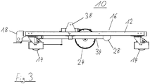
- Fig. 2 shows a plan view of the transport device 10 according to Fig. 1 and Fig. 3 a side view of the transport device 10 according to Fig. 1 ,
- the transport device 10 can be driven by the drive wheel 24.
- the drive takes place by means of an electric motor via the drive device 26.
- an additional spring force is exerted on the Antriebsradschwenkbügel 20 by the spring 36, which acts as a compression spring, which causes the Antriebsradschwenkbügel 20 is pushed away from the chassis 12. This additionally increases the contact pressure of the drive wheel 24 to the ground.
Landscapes
- Engineering & Computer Science (AREA)
- Chemical & Material Sciences (AREA)
- Combustion & Propulsion (AREA)
- Transportation (AREA)
- Mechanical Engineering (AREA)
- Handcart (AREA)
Applications Claiming Priority (1)
| Application Number | Priority Date | Filing Date | Title |
|---|---|---|---|
| DE102016101490.7A DE102016101490A1 (de) | 2016-01-28 | 2016-01-28 | Transportgerät |
Publications (2)
| Publication Number | Publication Date |
|---|---|
| EP3202636A1 true EP3202636A1 (fr) | 2017-08-09 |
| EP3202636B1 EP3202636B1 (fr) | 2021-09-15 |
Family
ID=57539079
Family Applications (1)
| Application Number | Title | Priority Date | Filing Date |
|---|---|---|---|
| EP16202860.9A Active EP3202636B1 (fr) | 2016-01-28 | 2016-12-08 | Appareil de transport |
Country Status (2)
| Country | Link |
|---|---|
| EP (1) | EP3202636B1 (fr) |
| DE (1) | DE102016101490A1 (fr) |
Cited By (1)
| Publication number | Priority date | Publication date | Assignee | Title |
|---|---|---|---|---|
| DE102020111434A1 (de) | 2020-04-27 | 2021-10-28 | Baumeister GmbH & Co. KG | Antriebseinheit und rollbare Plattform |
Families Citing this family (5)
| Publication number | Priority date | Publication date | Assignee | Title |
|---|---|---|---|---|
| PL3826898T3 (pl) * | 2018-07-23 | 2025-02-17 | Pietro Laudani | Wózek dwukierunkowy |
| DE102019101484B3 (de) | 2019-01-22 | 2020-02-20 | Wanzl Metallwarenfabrik Gmbh | Rollcontainer sowie Verfahren zum Transportieren und Lagern von Gegenständen |
| AU2020426864B2 (en) * | 2020-01-28 | 2024-07-04 | Sew-Eurodrive Gmbh & Co. Kg | Mobile transport system |
| USD1007091S1 (en) * | 2021-02-10 | 2023-12-05 | Intermetro Industries Corporation | Closed case cart |
| CN115892171B (zh) * | 2023-03-13 | 2023-05-26 | 山西太水市政工程有限公司 | 市政工程施工用管道搬运装置 |
Citations (10)
| Publication number | Priority date | Publication date | Assignee | Title |
|---|---|---|---|---|
| US2973823A (en) | 1959-09-02 | 1961-03-07 | Swartzbaugh Mfg Company | Power wheel unit |
| DE2058729A1 (de) | 1970-11-30 | 1972-06-08 | Bosch Gmbh Robert | Von einer Batterie gespeiste elektrische Antriebseinrichtung |
| US3942449A (en) * | 1972-06-01 | 1976-03-09 | Ltv Aerospace Corporation | Transportation system |
| EP0653341A1 (fr) * | 1993-11-16 | 1995-05-17 | Jonathan Moore | Chariot entrainé par un moteur |
| EP0770535B1 (fr) | 1995-10-24 | 1999-04-21 | Brüder Siegel GmbH + Co. KG Draht- und Metallwarenfabrik | Chariot de transport emboítable |
| EP1003663B1 (fr) | 1998-06-18 | 2004-10-06 | Wanzl Metallwarenfabrik Gmbh | Chariot de transport deplacable manuellement |
| EP1242275B1 (fr) | 2000-10-23 | 2005-03-30 | Wanzl Metallwarenfabrik Gmbh | Dispositif de transport pouvant etre mu manuellement |
| FR2872475A1 (fr) * | 2004-06-30 | 2006-01-06 | Jacques Henri Pa Dallongeville | Plateau porte charge roulant elevateur |
| EP1640255A1 (fr) * | 2003-04-08 | 2006-03-29 | Gabriel Benet Soler | Vehicule articule |
| GB2501771A (en) * | 2012-05-04 | 2013-11-06 | Numatic Int Ltd | Trolley |
-
2016
- 2016-01-28 DE DE102016101490.7A patent/DE102016101490A1/de not_active Ceased
- 2016-12-08 EP EP16202860.9A patent/EP3202636B1/fr active Active
Patent Citations (10)
| Publication number | Priority date | Publication date | Assignee | Title |
|---|---|---|---|---|
| US2973823A (en) | 1959-09-02 | 1961-03-07 | Swartzbaugh Mfg Company | Power wheel unit |
| DE2058729A1 (de) | 1970-11-30 | 1972-06-08 | Bosch Gmbh Robert | Von einer Batterie gespeiste elektrische Antriebseinrichtung |
| US3942449A (en) * | 1972-06-01 | 1976-03-09 | Ltv Aerospace Corporation | Transportation system |
| EP0653341A1 (fr) * | 1993-11-16 | 1995-05-17 | Jonathan Moore | Chariot entrainé par un moteur |
| EP0770535B1 (fr) | 1995-10-24 | 1999-04-21 | Brüder Siegel GmbH + Co. KG Draht- und Metallwarenfabrik | Chariot de transport emboítable |
| EP1003663B1 (fr) | 1998-06-18 | 2004-10-06 | Wanzl Metallwarenfabrik Gmbh | Chariot de transport deplacable manuellement |
| EP1242275B1 (fr) | 2000-10-23 | 2005-03-30 | Wanzl Metallwarenfabrik Gmbh | Dispositif de transport pouvant etre mu manuellement |
| EP1640255A1 (fr) * | 2003-04-08 | 2006-03-29 | Gabriel Benet Soler | Vehicule articule |
| FR2872475A1 (fr) * | 2004-06-30 | 2006-01-06 | Jacques Henri Pa Dallongeville | Plateau porte charge roulant elevateur |
| GB2501771A (en) * | 2012-05-04 | 2013-11-06 | Numatic Int Ltd | Trolley |
Cited By (1)
| Publication number | Priority date | Publication date | Assignee | Title |
|---|---|---|---|---|
| DE102020111434A1 (de) | 2020-04-27 | 2021-10-28 | Baumeister GmbH & Co. KG | Antriebseinheit und rollbare Plattform |
Also Published As
| Publication number | Publication date |
|---|---|
| DE102016101490A1 (de) | 2017-08-03 |
| EP3202636B1 (fr) | 2021-09-15 |
Similar Documents
| Publication | Publication Date | Title |
|---|---|---|
| EP3202636B1 (fr) | Appareil de transport | |
| EP3034323B1 (fr) | Véhicule à roue mécanum et procédé de fonctionnement | |
| EP2870102B1 (fr) | Dispositif de levage et procédé de montage et de démontage d'une roue au moyen d'un tel dispositif de levage | |
| DE102014106928A1 (de) | Gleisloser Routenzug | |
| DE102015107102B4 (de) | Mecanumradfahrzeug sowie Betriebsverfahren | |
| EP3263510A1 (fr) | Dispositif d'étayement comprenant un dispositif de réduction de vibrations | |
| DE2262835C3 (de) | Aufhängung für eine abgefederte starre Radachse | |
| AT525739B1 (de) | Fahrzeugträger für einen Fahrwerksprüfstand und Verfahren zur Rüstung eines Fahrwerksprüfstandes mit einem derartigen Fahrzeugträger | |
| EP3998170A1 (fr) | Remorque de train routier | |
| DE2250428C3 (de) | Hebegerät für Fahrzeuge, insbesondere Kraftfahrzeuge | |
| EP1932799B1 (fr) | Chariot de manutention | |
| DE3148799C2 (de) | Lenkrolle | |
| EP2662261B1 (fr) | Support à roulette pour déplacer une charge | |
| EP3309111B1 (fr) | Chariot de manutention | |
| EP0530742A2 (fr) | Chariot de manutention à fourches pour palettes | |
| DE102009040850B4 (de) | Holzspalter | |
| WO2009146836A1 (fr) | Dispositif de transport | |
| DE19626119A1 (de) | Rangierwagenheber | |
| DE102013112633B4 (de) | Deichselhubwagen | |
| EP0061643A2 (fr) | Chevalet de montage mobile | |
| DE4309692C2 (de) | Hebebock zum Anheben und Abstützen schwerer Lasten | |
| DD259556A1 (de) | Nachlaufrad fuer gezogene und geschobene landmaschinen | |
| DE102022115845A1 (de) | Flurförderzeug | |
| WO2017161397A1 (fr) | Engin pourvu d'un système de levage latéral | |
| EP3056180B1 (fr) | Chassis de plateforme patient rotative |
Legal Events
| Date | Code | Title | Description |
|---|---|---|---|
| PUAI | Public reference made under article 153(3) epc to a published international application that has entered the european phase |
Free format text: ORIGINAL CODE: 0009012 |
|
| STAA | Information on the status of an ep patent application or granted ep patent |
Free format text: STATUS: THE APPLICATION HAS BEEN PUBLISHED |
|
| AK | Designated contracting states |
Kind code of ref document: A1 Designated state(s): AL AT BE BG CH CY CZ DE DK EE ES FI FR GB GR HR HU IE IS IT LI LT LU LV MC MK MT NL NO PL PT RO RS SE SI SK SM TR |
|
| AX | Request for extension of the european patent |
Extension state: BA ME |
|
| STAA | Information on the status of an ep patent application or granted ep patent |
Free format text: STATUS: REQUEST FOR EXAMINATION WAS MADE |
|
| 17P | Request for examination filed |
Effective date: 20180209 |
|
| RBV | Designated contracting states (corrected) |
Designated state(s): AL AT BE BG CH CY CZ DE DK EE ES FI FR GB GR HR HU IE IS IT LI LT LU LV MC MK MT NL NO PL PT RO RS SE SI SK SM TR |
|
| STAA | Information on the status of an ep patent application or granted ep patent |
Free format text: STATUS: EXAMINATION IS IN PROGRESS |
|
| 17Q | First examination report despatched |
Effective date: 20181011 |
|
| RAP1 | Party data changed (applicant data changed or rights of an application transferred) |
Owner name: WANZL GMBH & CO. KGAA |
|
| GRAP | Despatch of communication of intention to grant a patent |
Free format text: ORIGINAL CODE: EPIDOSNIGR1 |
|
| STAA | Information on the status of an ep patent application or granted ep patent |
Free format text: STATUS: GRANT OF PATENT IS INTENDED |
|
| INTG | Intention to grant announced |
Effective date: 20210629 |
|
| GRAS | Grant fee paid |
Free format text: ORIGINAL CODE: EPIDOSNIGR3 |
|
| GRAA | (expected) grant |
Free format text: ORIGINAL CODE: 0009210 |
|
| STAA | Information on the status of an ep patent application or granted ep patent |
Free format text: STATUS: THE PATENT HAS BEEN GRANTED |
|
| AK | Designated contracting states |
Kind code of ref document: B1 Designated state(s): AL AT BE BG CH CY CZ DE DK EE ES FI FR GB GR HR HU IE IS IT LI LT LU LV MC MK MT NL NO PL PT RO RS SE SI SK SM TR |
|
| REG | Reference to a national code |
Ref country code: CH Ref legal event code: EP Ref country code: GB Ref legal event code: FG4D Free format text: NOT ENGLISH |
|
| REG | Reference to a national code |
Ref country code: DE Ref legal event code: R096 Ref document number: 502016013828 Country of ref document: DE |
|
| REG | Reference to a national code |
Ref country code: IE Ref legal event code: FG4D Free format text: LANGUAGE OF EP DOCUMENT: GERMAN |
|
| REG | Reference to a national code |
Ref country code: AT Ref legal event code: REF Ref document number: 1430300 Country of ref document: AT Kind code of ref document: T Effective date: 20211015 |
|
| REG | Reference to a national code |
Ref country code: NL Ref legal event code: FP |
|
| REG | Reference to a national code |
Ref country code: LT Ref legal event code: MG9D |
|
| PG25 | Lapsed in a contracting state [announced via postgrant information from national office to epo] |
Ref country code: SE Free format text: LAPSE BECAUSE OF FAILURE TO SUBMIT A TRANSLATION OF THE DESCRIPTION OR TO PAY THE FEE WITHIN THE PRESCRIBED TIME-LIMIT Effective date: 20210915 Ref country code: RS Free format text: LAPSE BECAUSE OF FAILURE TO SUBMIT A TRANSLATION OF THE DESCRIPTION OR TO PAY THE FEE WITHIN THE PRESCRIBED TIME-LIMIT Effective date: 20210915 Ref country code: HR Free format text: LAPSE BECAUSE OF FAILURE TO SUBMIT A TRANSLATION OF THE DESCRIPTION OR TO PAY THE FEE WITHIN THE PRESCRIBED TIME-LIMIT Effective date: 20210915 Ref country code: LT Free format text: LAPSE BECAUSE OF FAILURE TO SUBMIT A TRANSLATION OF THE DESCRIPTION OR TO PAY THE FEE WITHIN THE PRESCRIBED TIME-LIMIT Effective date: 20210915 Ref country code: BG Free format text: LAPSE BECAUSE OF FAILURE TO SUBMIT A TRANSLATION OF THE DESCRIPTION OR TO PAY THE FEE WITHIN THE PRESCRIBED TIME-LIMIT Effective date: 20211215 Ref country code: NO Free format text: LAPSE BECAUSE OF FAILURE TO SUBMIT A TRANSLATION OF THE DESCRIPTION OR TO PAY THE FEE WITHIN THE PRESCRIBED TIME-LIMIT Effective date: 20211215 Ref country code: FI Free format text: LAPSE BECAUSE OF FAILURE TO SUBMIT A TRANSLATION OF THE DESCRIPTION OR TO PAY THE FEE WITHIN THE PRESCRIBED TIME-LIMIT Effective date: 20210915 |
|
| PG25 | Lapsed in a contracting state [announced via postgrant information from national office to epo] |
Ref country code: LV Free format text: LAPSE BECAUSE OF FAILURE TO SUBMIT A TRANSLATION OF THE DESCRIPTION OR TO PAY THE FEE WITHIN THE PRESCRIBED TIME-LIMIT Effective date: 20210915 Ref country code: GR Free format text: LAPSE BECAUSE OF FAILURE TO SUBMIT A TRANSLATION OF THE DESCRIPTION OR TO PAY THE FEE WITHIN THE PRESCRIBED TIME-LIMIT Effective date: 20211216 |
|
| PG25 | Lapsed in a contracting state [announced via postgrant information from national office to epo] |
Ref country code: IS Free format text: LAPSE BECAUSE OF FAILURE TO SUBMIT A TRANSLATION OF THE DESCRIPTION OR TO PAY THE FEE WITHIN THE PRESCRIBED TIME-LIMIT Effective date: 20220115 Ref country code: SM Free format text: LAPSE BECAUSE OF FAILURE TO SUBMIT A TRANSLATION OF THE DESCRIPTION OR TO PAY THE FEE WITHIN THE PRESCRIBED TIME-LIMIT Effective date: 20210915 Ref country code: SK Free format text: LAPSE BECAUSE OF FAILURE TO SUBMIT A TRANSLATION OF THE DESCRIPTION OR TO PAY THE FEE WITHIN THE PRESCRIBED TIME-LIMIT Effective date: 20210915 Ref country code: RO Free format text: LAPSE BECAUSE OF FAILURE TO SUBMIT A TRANSLATION OF THE DESCRIPTION OR TO PAY THE FEE WITHIN THE PRESCRIBED TIME-LIMIT Effective date: 20210915 Ref country code: PT Free format text: LAPSE BECAUSE OF FAILURE TO SUBMIT A TRANSLATION OF THE DESCRIPTION OR TO PAY THE FEE WITHIN THE PRESCRIBED TIME-LIMIT Effective date: 20220117 Ref country code: PL Free format text: LAPSE BECAUSE OF FAILURE TO SUBMIT A TRANSLATION OF THE DESCRIPTION OR TO PAY THE FEE WITHIN THE PRESCRIBED TIME-LIMIT Effective date: 20210915 Ref country code: ES Free format text: LAPSE BECAUSE OF FAILURE TO SUBMIT A TRANSLATION OF THE DESCRIPTION OR TO PAY THE FEE WITHIN THE PRESCRIBED TIME-LIMIT Effective date: 20210915 Ref country code: EE Free format text: LAPSE BECAUSE OF FAILURE TO SUBMIT A TRANSLATION OF THE DESCRIPTION OR TO PAY THE FEE WITHIN THE PRESCRIBED TIME-LIMIT Effective date: 20210915 Ref country code: CZ Free format text: LAPSE BECAUSE OF FAILURE TO SUBMIT A TRANSLATION OF THE DESCRIPTION OR TO PAY THE FEE WITHIN THE PRESCRIBED TIME-LIMIT Effective date: 20210915 Ref country code: AL Free format text: LAPSE BECAUSE OF FAILURE TO SUBMIT A TRANSLATION OF THE DESCRIPTION OR TO PAY THE FEE WITHIN THE PRESCRIBED TIME-LIMIT Effective date: 20210915 |
|
| REG | Reference to a national code |
Ref country code: DE Ref legal event code: R097 Ref document number: 502016013828 Country of ref document: DE |
|
| PLBE | No opposition filed within time limit |
Free format text: ORIGINAL CODE: 0009261 |
|
| STAA | Information on the status of an ep patent application or granted ep patent |
Free format text: STATUS: NO OPPOSITION FILED WITHIN TIME LIMIT |
|
| PG25 | Lapsed in a contracting state [announced via postgrant information from national office to epo] |
Ref country code: MC Free format text: LAPSE BECAUSE OF FAILURE TO SUBMIT A TRANSLATION OF THE DESCRIPTION OR TO PAY THE FEE WITHIN THE PRESCRIBED TIME-LIMIT Effective date: 20210915 Ref country code: DK Free format text: LAPSE BECAUSE OF FAILURE TO SUBMIT A TRANSLATION OF THE DESCRIPTION OR TO PAY THE FEE WITHIN THE PRESCRIBED TIME-LIMIT Effective date: 20210915 |
|
| REG | Reference to a national code |
Ref country code: CH Ref legal event code: PL |
|
| 26N | No opposition filed |
Effective date: 20220616 |
|
| PG25 | Lapsed in a contracting state [announced via postgrant information from national office to epo] |
Ref country code: SI Free format text: LAPSE BECAUSE OF FAILURE TO SUBMIT A TRANSLATION OF THE DESCRIPTION OR TO PAY THE FEE WITHIN THE PRESCRIBED TIME-LIMIT Effective date: 20210915 |
|
| REG | Reference to a national code |
Ref country code: BE Ref legal event code: MM Effective date: 20211231 |
|
| PG25 | Lapsed in a contracting state [announced via postgrant information from national office to epo] |
Ref country code: LU Free format text: LAPSE BECAUSE OF NON-PAYMENT OF DUE FEES Effective date: 20211208 Ref country code: IE Free format text: LAPSE BECAUSE OF NON-PAYMENT OF DUE FEES Effective date: 20211208 |
|
| PG25 | Lapsed in a contracting state [announced via postgrant information from national office to epo] |
Ref country code: BE Free format text: LAPSE BECAUSE OF NON-PAYMENT OF DUE FEES Effective date: 20211231 |
|
| PG25 | Lapsed in a contracting state [announced via postgrant information from national office to epo] |
Ref country code: LI Free format text: LAPSE BECAUSE OF NON-PAYMENT OF DUE FEES Effective date: 20211231 Ref country code: CH Free format text: LAPSE BECAUSE OF NON-PAYMENT OF DUE FEES Effective date: 20211231 |
|
| PG25 | Lapsed in a contracting state [announced via postgrant information from national office to epo] |
Ref country code: IT Free format text: LAPSE BECAUSE OF FAILURE TO SUBMIT A TRANSLATION OF THE DESCRIPTION OR TO PAY THE FEE WITHIN THE PRESCRIBED TIME-LIMIT Effective date: 20210915 |
|
| REG | Reference to a national code |
Ref country code: AT Ref legal event code: MM01 Ref document number: 1430300 Country of ref document: AT Kind code of ref document: T Effective date: 20211208 |
|
| PG25 | Lapsed in a contracting state [announced via postgrant information from national office to epo] |
Ref country code: AT Free format text: LAPSE BECAUSE OF NON-PAYMENT OF DUE FEES Effective date: 20211208 |
|
| PG25 | Lapsed in a contracting state [announced via postgrant information from national office to epo] |
Ref country code: HU Free format text: LAPSE BECAUSE OF FAILURE TO SUBMIT A TRANSLATION OF THE DESCRIPTION OR TO PAY THE FEE WITHIN THE PRESCRIBED TIME-LIMIT; INVALID AB INITIO Effective date: 20161208 |
|
| P01 | Opt-out of the competence of the unified patent court (upc) registered |
Effective date: 20230523 |
|
| PG25 | Lapsed in a contracting state [announced via postgrant information from national office to epo] |
Ref country code: CY Free format text: LAPSE BECAUSE OF FAILURE TO SUBMIT A TRANSLATION OF THE DESCRIPTION OR TO PAY THE FEE WITHIN THE PRESCRIBED TIME-LIMIT Effective date: 20210915 |
|
| PG25 | Lapsed in a contracting state [announced via postgrant information from national office to epo] |
Ref country code: MK Free format text: LAPSE BECAUSE OF FAILURE TO SUBMIT A TRANSLATION OF THE DESCRIPTION OR TO PAY THE FEE WITHIN THE PRESCRIBED TIME-LIMIT Effective date: 20210915 |
|
| PG25 | Lapsed in a contracting state [announced via postgrant information from national office to epo] |
Ref country code: MT Free format text: LAPSE BECAUSE OF FAILURE TO SUBMIT A TRANSLATION OF THE DESCRIPTION OR TO PAY THE FEE WITHIN THE PRESCRIBED TIME-LIMIT Effective date: 20210915 |
|
| PG25 | Lapsed in a contracting state [announced via postgrant information from national office to epo] |
Ref country code: TR Free format text: LAPSE BECAUSE OF FAILURE TO SUBMIT A TRANSLATION OF THE DESCRIPTION OR TO PAY THE FEE WITHIN THE PRESCRIBED TIME-LIMIT Effective date: 20210915 |
|
| PGFP | Annual fee paid to national office [announced via postgrant information from national office to epo] |
Ref country code: GB Payment date: 20251218 Year of fee payment: 10 |
|
| PGFP | Annual fee paid to national office [announced via postgrant information from national office to epo] |
Ref country code: FR Payment date: 20251218 Year of fee payment: 10 Ref country code: NL Payment date: 20251217 Year of fee payment: 10 |
|
| PGFP | Annual fee paid to national office [announced via postgrant information from national office to epo] |
Ref country code: DE Payment date: 20251231 Year of fee payment: 10 |