EP3202644B1 - Achse eines fahrzeugs mit einer nachlauflenkung, ausgestattet mit einer vorrichtung zum assistierten lenken - Google Patents
Achse eines fahrzeugs mit einer nachlauflenkung, ausgestattet mit einer vorrichtung zum assistierten lenken Download PDFInfo
- Publication number
- EP3202644B1 EP3202644B1 EP17153691.5A EP17153691A EP3202644B1 EP 3202644 B1 EP3202644 B1 EP 3202644B1 EP 17153691 A EP17153691 A EP 17153691A EP 3202644 B1 EP3202644 B1 EP 3202644B1
- Authority
- EP
- European Patent Office
- Prior art keywords
- axle
- fluid
- valve
- relief
- cylinder
- Prior art date
- Legal status (The legal status is an assumption and is not a legal conclusion. Google has not performed a legal analysis and makes no representation as to the accuracy of the status listed.)
- Not-in-force
Links
- 239000012530 fluid Substances 0.000 claims description 39
- 230000037361 pathway Effects 0.000 claims description 14
- 230000000694 effects Effects 0.000 claims description 4
- 238000010586 diagram Methods 0.000 description 6
- 230000008867 communication pathway Effects 0.000 description 1
- 238000001514 detection method Methods 0.000 description 1
- 238000006073 displacement reaction Methods 0.000 description 1
- 230000005484 gravity Effects 0.000 description 1
- 239000000463 material Substances 0.000 description 1
- 238000012986 modification Methods 0.000 description 1
- 230000004048 modification Effects 0.000 description 1
- 230000001105 regulatory effect Effects 0.000 description 1
Images


Classifications
-
- B—PERFORMING OPERATIONS; TRANSPORTING
- B62—LAND VEHICLES FOR TRAVELLING OTHERWISE THAN ON RAILS
- B62D—MOTOR VEHICLES; TRAILERS
- B62D7/00—Steering linkage; Stub axles or their mountings
- B62D7/06—Steering linkage; Stub axles or their mountings for individually-pivoted wheels, e.g. on king-pins
- B62D7/14—Steering linkage; Stub axles or their mountings for individually-pivoted wheels, e.g. on king-pins the pivotal axes being situated in more than one plane transverse to the longitudinal centre line of the vehicle, e.g. all-wheel steering
- B62D7/142—Steering linkage; Stub axles or their mountings for individually-pivoted wheels, e.g. on king-pins the pivotal axes being situated in more than one plane transverse to the longitudinal centre line of the vehicle, e.g. all-wheel steering specially adapted for particular vehicles, e.g. tractors, carts, earth-moving vehicles, trucks
- B62D7/144—Steering linkage; Stub axles or their mountings for individually-pivoted wheels, e.g. on king-pins the pivotal axes being situated in more than one plane transverse to the longitudinal centre line of the vehicle, e.g. all-wheel steering specially adapted for particular vehicles, e.g. tractors, carts, earth-moving vehicles, trucks for vehicles with more than two axles
-
- B—PERFORMING OPERATIONS; TRANSPORTING
- B62—LAND VEHICLES FOR TRAVELLING OTHERWISE THAN ON RAILS
- B62D—MOTOR VEHICLES; TRAILERS
- B62D13/00—Steering specially adapted for trailers
- B62D13/04—Steering specially adapted for trailers for individually-pivoted wheels
-
- B—PERFORMING OPERATIONS; TRANSPORTING
- B62—LAND VEHICLES FOR TRAVELLING OTHERWISE THAN ON RAILS
- B62D—MOTOR VEHICLES; TRAILERS
- B62D7/00—Steering linkage; Stub axles or their mountings
- B62D7/06—Steering linkage; Stub axles or their mountings for individually-pivoted wheels, e.g. on king-pins
- B62D7/14—Steering linkage; Stub axles or their mountings for individually-pivoted wheels, e.g. on king-pins the pivotal axes being situated in more than one plane transverse to the longitudinal centre line of the vehicle, e.g. all-wheel steering
- B62D7/148—Steering linkage; Stub axles or their mountings for individually-pivoted wheels, e.g. on king-pins the pivotal axes being situated in more than one plane transverse to the longitudinal centre line of the vehicle, e.g. all-wheel steering provided with safety devices
Definitions
- the present invention relates to a self-steering axle of a vehicle equipped with an assisted steering device, and more precisely to an axle having a self-tracking steering which, as is known, is of a type in which the steering angle is modified only by the system of forces that originate from the adherence of the wheel to the ground.
- the axle follows the trajectory imposed by the other vehicle axles by effect of the geometry thereof characterised by the position of the steering hinge, which is advanced with respect to the axis of instantaneous rotation of the wheel.
- the system of forces originating from the adherence of the wheel to the ground generates a momentum with respect to said hinge axis that is able to direct the wheel in the above-mentioned direction.
- a known device is a cylinder solidly constrained to the body of the self-steering axle, in which a rod is slidably housed having the two ends thereof exiting from the cylinder connected to the steering arms.
- a pump mounted on the vehicle generates, in the supply line, a fluid pressure sufficient to return and lock the rod in the position corresponding to the rectilinear driving condition.
- the cylinder can be directly commanded by the operator or automatically using sensors and devices able to detect the operating conditions of the vehicle and command the locking system in consequence of the detections.
- control can comprise phonic wheels and sensors, alike to those used for ABS systems, which detect both the velocity and the direction of movement of the vehicle, so as to carry out the control both in reverse and fast motion.
- the realignment can take place only by effect of the forces generated by the dynamics of the movement.
- EP2272736 A1 , EP2465753 A1 and WO2014/047842 A1 disclose an axle of a vehicle with a self-tracking steering according to the preamble of claim 1.
- the technical task of the present invention is to make available an axle of a vehicle with self-tracking steering, provided with an assisted steering device which enables an effective and rapid realignment of the axle after passing round a bend.
- said relief valve is a three-way valve.
- said relief valve has an inflow pathway for the fluid, a delivery pathway for the fluid and a relief pathway for the fluid, which is connected to a fluid relief line.
- said disabling means comprises a shut-off solenoid valve on said relief line.
- said pressure relief valve on said fluid supply line is a proportional valve.
- said supply line comprises a non-return valve between said source of pressurized fluid and said pressure relief valve.
- said supply line comprises a shut-off solenoid valve.
- the assisted steering device advantageously therefore provides an active auxiliary function, a locking function of the axle in realigned trim, and a release function of the axle from the re-aligned trim.
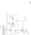
- the axle 1 is equipped with an assisted steering device comprising an oil-hydraulic actuator 2 supplied by a fluid supply line 3 connected to a source of pressurized fluid comprising a supply pump 10.
- the assisted steering device advantageously comprises a pressure relief valve 4 on the fluid supply line 3.
- the relief valve 4 is of the type that can be located on the market and will for this reason not be further described in detail.
- the relief valve 4 is a direct-acting pressure reduction valve, for example commercially known as ZDRK, produced by BoschTM. It is of the three-way type and therefore comprises an inflow pathway for the pressurized fluid source, a delivery pathway for the pressurized fluid connected to the actuator 2, and a relief pathway of the fluid connected to a relief line 6 of the fluid comprising a discharge tank 12.
- the disabling means 5 comprises a shut-off solenoid valve 7 on the relief line 6.
- the shut-off solenoid valve 7 switches to the closed position of the relief line 6 in order to prevent release of the pressurized fluid which would thus disable the relief function of the relief valve 4.
- the relief valve 4 is a proportional pressure reduction valve, for example commercially known as DRE or ZDRE, produced by BoschTM.
- DRE proportional pressure reduction valve
- ZDRE ZDRE
- the circuit diagram is simplified due to the fact that it is no longer necessary to include special disabling means that is structurally independent of the pressure limiting valve 4, given that the function of the disabling means can be carried out naturally by the proportional relief valve 4 itself.
- the supply line 3 comprises a non-return valve 8 between the source of pressurized fluid and the pressure relief valve 4.
- the supply line 3 comprises a shut-off solenoid valve 9 positioned between the non-return valve 8 and the source of pressurized fluid.
- the supply pump 10 and the shut-off solenoid valve 9 are mounted on the tractor vehicle while the non-return valve 8 and the pressure relief valve are mounted on the trailer of the vehicle.
- the assisted steering device also has a line 11 for resetting the pressure of the fluid in the actuator 2, connecting the delivery pathway of the pressure relief valve 4 to the discharge tank 12.
- the pressure resetting line 11 also comprises a shut-off solenoid valve 13, also preferably mounted on the trailer of the vehicle, like the shut-off solenoid valve 7.
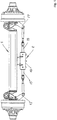
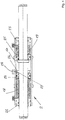
- the oil-hydraulic actuator 2 comprises a hollow cylinder 14 fixed to the axle 1 and a rod 15 axially slidable in the cylinder 14.
- the rod 15 has ends 15' protruding from the cylinder 14 that are connectable to steering arms 17 of the vehicle.
- the rod 15 further has a fixed annular protrusion 16.
- the cylinder 14 has a first chamber 18 and a second chamber 19 having variable volumes.
- Each chamber 18, 19 is provided with a respective feeding mouth 20, 21 connected to the delivery pathway of the pressure relief valve 4.
- Each chamber 18, 19 is delimited by a respective fixed sleeve 22, 23 opposite the annular protrusion 16 and a respective slidable sleeve 24, 25 adjacent to the annular protrusion 16.
- Each fixed sleeve 22, 23 and each slidable sleeve 24, 25 has an internal surface joined to the lateral surface of the rod 15 and an external surface joined to the internal lateral surface of the cylinder 14.
- Suitable fluid seals are interposed between the joined surfaces.
- Each fixed sleeve 22, 23 is rigidly connected to ends of the cylinder 14 and guides the axial sliding of the rod 15 with the internal surface thereof.
- Each sliding sleeve 24, 25 is slidable along the axis of the cylinder 14 both with respect to the cylinder 14 and with respect to the rod 15 and has a first travel limit stop defined by the fixed sleeve 22, 23 adjacent thereto and a second travel limit stop defined by a ring 26 fixed centrally along an internal perimeter circumference of the cylinder 14.
- the fixed ring 26 has a connecting hole 27 to a relief mouth 28 afforded through the thickness of the cylinder wall 14.
- the sliding sleeves 24, 25 are able to interact with the protrusion 16 of the rod 15 so as to displace it, in order to modify the driving condition of the wheels.
- the rectilinear driving condition of the wheels is defined by the alignment of the protrusion 16 to the fixed ring 26.
- the controller of the assisted steering device is configured for switching the disabling means 5 from an enabled state, for locking the axle in rectilinear driving condition, to a disabled state, for assisting the return of the axle to a rectilinear driving condition, and for switching the state of the shut-off solenoid valves.
- the assisted steering device is disengaged since the flow from the tractor vehicle to the trailer is interrupted by the normally-closed shut-off solenoid valve 9.
- the assisted steering device is in an active auxiliary configuration, activated by powering the solenoid valve 9 which opens, while the normally-open solenoid valve 7 and the normally-closed solenoid valve 13 are not supplied and thus remain in this state.
- the fluid can flow through the relief line 6 towards the tank 12 and the relief valve 4 can carry out the function thereof, injecting fluid at a controlled pressure through the feeding mouths 21, 22.
- Each displacement of the rod 15 from said central position is thus obstructed by the relative sliding sleeve 24, 25 with a force that is proportional to the pressure of the fluid injected into the cylinder 14 regulated by the relief valve 4.
- the assisted steering device is in a locked configuration of the axle in rectilinear movement trim obtained by increasing the pressure internally of the cylinder 14 up to the maximum value dispensed by the supply pump 10 so as to prevent any movement of the rod 15 impressed by the forces generated during the movement of the vehicle.
- the locked configuration is activated by keeping the solenoid valve 9 supplied, which solenoid valve 9 remains open, supplying the solenoid valve 7 which closes, and leaving the solenoid valve 13 that remains closed deactivated.
- the fluid does not have an open pathway towards the discharge tank 12 and therefore the relief valve 4 is not able to carry out the function thereof and the pressure of the fluid in the cylinder 14 thus reaches the maximum value thereof.
- the assisted steering device is in an unlocked configuration of the axle obtained by supplying the solenoid valve 9, which opens, keeping the solenoid valve 7 unsupplied and therefore open and the solenoid valve 13 supplied and thus open.
- the whole fluid circuit is in communication with the tank 12 and therefore the fluid pressure in the cylinder 14 is annulled. Consequently, the steering is free.
- the controller When the hydraulic supply is disengaged, i.e. both when the solenoid valve 9 is not supplied and when the supply pump 10 is off, for example because the tractor vehicle is unhooked from the trailer or the engine is switched off, the controller "freezes" the assisted steering device in the last activated configuration.
- the assisted steering device of a self-steering axle of a vehicle as conceived herein is susceptible to many modifications and variations, all falling within the scope of the invention as defined by the appendant claims.
- the materials used, as well as the dimensions, can be any according to needs and the state of the art.
Landscapes
- Engineering & Computer Science (AREA)
- Chemical & Material Sciences (AREA)
- Combustion & Propulsion (AREA)
- Transportation (AREA)
- Mechanical Engineering (AREA)
- Power Steering Mechanism (AREA)
Claims (7)
- Achse (1) eines Fahrzeugs mit einer Nachlauflenkung, wobei die Achse vom Typ ist, der der von den anderen Fahrzeugachsen durch deren Geometrie vorgegebenen Bahn folgt, wobei die Position des Lenkscharniers im Vergleich zur Achse der Momentandrehung des Rads vorgeschoben ist, sodass der Lenkwinkel durch das System der Kräfte verändert wird, die durch die Haftung des Rads auf dem Boden erzeugt werden, wobei die Achse mit einer Vorrichtung zum assistierten Lenken ausgestattet ist, umfassend ein Hydraulikaggregat, das durch eine Mediumversorgungsleitung (3) gespeist wird, verbunden mit einer Quelle für ein mit Druck beaufschlagtes Medium, umfassend eine Pumpe (10), wobei sie ein Druckablassventil (4) an der Mediumversorgungsleitung (3) umfasst und wobei das Hydraulikaggregat einen Zylinder (14) umfasst, der an der Achse (1) gesichert werden kann, einen Stab (15), der im Zylinder (14) verschiebbar ist und der einen ringförmigen Vorsprung (16) und Enden (15') aufweist, die aus dem Zylinder (14) hervorstehen, die mit den Lenkarmen des Fahrzeugs verbunden werden können, eine erste (18) und eine zweite (19) Kammer des Zylinders (14) an entgegengesetzten Seiten des Vorsprungs (16), wobei eine jede Kammer (18, 19) mit einer Zuführungsöffnung (20, 21) versehen ist, verbunden mit der Mediumversorgungsleitung (3) und abgegrenzt durch eine fixierte Hülse (22, 23), gegenständig zum Vorsprung (16), und eine Hülse (24, 25), angrenzend an den Vorsprung (16) und verschiebbar entlang des Stabs (15), sodass sie mit dem Vorsprung (16) interagiert, und einen Verfahrendanschlag für die verschiebbaren Hülsen (24, 25) an der Position des Vorsprungs (16), mit dem ein geradliniger Fahrzustand assoziiert ist, dadurch gekennzeichnet, dass sie Mittel (5) zum Deaktivieren des Ablassventils (4) umfasst, dadurch, dass sie eine Leitung (11) zum Zurücksetzen des Drucks des Mediums im Aggregat umfasst, umfassend ein Absperrmagnetventil (13), und dadurch, dass sie eine Steuerung für das Ablassventil (4) umfasst, um dieses von einem Zustand, in dem es mit der Verriegelung der Achse (1) in einem geradlinigen Fahrzustand assoziiert ist, in dem die Deaktivierungsmittel aktiviert sind, das Absperrmagnetventil (13) geschlossen ist und das Aggregat mit dem maximalen Druck der Pumpe (10) gespeist wird, in einen Zustand der Unterstützung der Rückführung der Achse (1) in einen geradlinigen Fahrzustand umzuschalten, in dem die Deaktivierungsmittel deaktiviert sind, das Absperrmagnetventil (13) geschlossen ist und das Aggregat mit dem durch das Ablassventil (4) begrenzten Druck gespeist wird, wobei die Steuerung das Absperrmagnetventil (13) der Rücksetzungsleitung (11) in den offenen Zustand für die freie Lenkung der Achse (1) umschaltet, in der der Druck im Zylinder (14) aufgehoben ist.
- Achse (1) nach Anspruch 1, dadurch gekennzeichnet, dass das Ablassventil (4) ein Dreiwegeventil ist.
- Achse (1) nach Anspruch 1, dadurch gekennzeichnet, dass das Ablassventil (4) einen Einströmungsweg für das Medium, einen Ausströmungsweg für das Medium und einen Ablassweg für das Medium aufweist, der mit einer Mediumablassleitung (6) verbunden ist.
- Achse (1) nach Anspruch 1, dadurch gekennzeichnet, dass die Deaktivierungsmittel (5) ein Absperrmagnetventil (7) an der Ablassleitung (6) umfassen.
- Achse (1) nach Anspruch 1, dadurch gekennzeichnet, dass das Ablassventil (4) ein Proportionalventil ist.
- Achse (1) nach Anspruch 1, dadurch gekennzeichnet, dass die Versorgungsleitung (3) ein Rückschlagventil (8) zwischen der Quelle des mit Druck beaufschlagten Mediums und dem Druckablassventil (4) umfasst.
- Achse (1) nach Anspruch 1, dadurch gekennzeichnet, dass die Versorgungsleitung (3) ein Absperrmagnetventil (9) umfasst.
Applications Claiming Priority (1)
| Application Number | Priority Date | Filing Date | Title |
|---|---|---|---|
| ITUB2016A000336A ITUB20160336A1 (it) | 2016-02-02 | 2016-02-02 | Dispositivo di assistenza alla sterzata di un asse autosterzante di un veicolo |
Publications (2)
| Publication Number | Publication Date |
|---|---|
| EP3202644A1 EP3202644A1 (de) | 2017-08-09 |
| EP3202644B1 true EP3202644B1 (de) | 2018-12-05 |
Family
ID=55860986
Family Applications (1)
| Application Number | Title | Priority Date | Filing Date |
|---|---|---|---|
| EP17153691.5A Not-in-force EP3202644B1 (de) | 2016-02-02 | 2017-01-30 | Achse eines fahrzeugs mit einer nachlauflenkung, ausgestattet mit einer vorrichtung zum assistierten lenken |
Country Status (2)
| Country | Link |
|---|---|
| EP (1) | EP3202644B1 (de) |
| IT (1) | ITUB20160336A1 (de) |
Families Citing this family (2)
| Publication number | Priority date | Publication date | Assignee | Title |
|---|---|---|---|---|
| IT201800003510A1 (it) * | 2018-03-13 | 2019-09-13 | R P F S P A | Dispositivo di sterzatura per asse sterzante di un veicolo |
| CN109353403A (zh) * | 2018-12-06 | 2019-02-19 | 核心驱动科技(金华)有限公司 | 汽车转向传动机构及汽车转向系统 |
Citations (1)
| Publication number | Priority date | Publication date | Assignee | Title |
|---|---|---|---|---|
| US20090199603A1 (en) * | 2008-02-11 | 2009-08-13 | Agco Corporation | Steering lock indicator for self-steering axle |
Family Cites Families (4)
| Publication number | Priority date | Publication date | Assignee | Title |
|---|---|---|---|---|
| IT1314449B1 (it) * | 2000-10-31 | 2002-12-13 | Armando Biondi | Dispositivo cilindro attuatore oleopneumatico di comando rotazione edi autocentraggio per l'allineamento in guida rettilinea di assali |
| EP2272736A1 (de) * | 2009-07-09 | 2011-01-12 | A.D.R. S.p.A. | Steuerbare Achse für einen Anhänger |
| DE102010053920A1 (de) * | 2010-12-09 | 2012-06-14 | Hydac System Gmbh | Steuerungsvorrichtung zur Steuerung zumindest eines hydraulischen Steuerzylinders |
| WO2014047842A1 (zh) * | 2012-09-27 | 2014-04-03 | 中联重科股份有限公司 | 车辆对中控制系统和车辆 |
-
2016
- 2016-02-02 IT ITUB2016A000336A patent/ITUB20160336A1/it unknown
-
2017
- 2017-01-30 EP EP17153691.5A patent/EP3202644B1/de not_active Not-in-force
Patent Citations (1)
| Publication number | Priority date | Publication date | Assignee | Title |
|---|---|---|---|---|
| US20090199603A1 (en) * | 2008-02-11 | 2009-08-13 | Agco Corporation | Steering lock indicator for self-steering axle |
Also Published As
| Publication number | Publication date |
|---|---|
| EP3202644A1 (de) | 2017-08-09 |
| ITUB20160336A1 (it) | 2017-08-02 |
Similar Documents
| Publication | Publication Date | Title |
|---|---|---|
| US10370027B2 (en) | Steering system for a trailing axle of a vehicle | |
| US7686124B2 (en) | Vehicle steering systems | |
| US7959164B2 (en) | Roll control devices | |
| EP2981448B1 (de) | System zur lenkung einer nachlaufachse eines fahrzeugs | |
| US20170327147A1 (en) | Steering System for a Trailing Axle of a Vehicle | |
| US20130038118A1 (en) | System and method for brake assisted turning | |
| US8894005B2 (en) | Landing gear assembly of aircraft | |
| CN101254824A (zh) | 用于管理飞机的轮子转向控制的方法 | |
| US9764722B2 (en) | Brake system for controlling a brake of a unit hauled by a vehicle | |
| KR102273466B1 (ko) | 후륜조향장치 | |
| EP3202644B1 (de) | Achse eines fahrzeugs mit einer nachlauflenkung, ausgestattet mit einer vorrichtung zum assistierten lenken | |
| CN108137021A (zh) | 包括sahr制动器的动力车辆 | |
| CN104661899B (zh) | 用于车辆后从动轴的转向系统 | |
| US20100259023A1 (en) | Steerable wheel safety system | |
| CN102874305B (zh) | 车桥转向系统及其控制方法、工程车辆 | |
| EP2767456B1 (de) | Hydraulisches Servolenksystem mit magnetischer Drehmomentüberlagerung | |
| US7175134B2 (en) | Hydraulic damper for shimmy of aircraft landing gear | |
| EP2894069B1 (de) | Lenk- und Bremsanordnung | |
| US7694776B2 (en) | Hydraulic steering system with protection against uncontrolled steering movements | |
| EP3225473B1 (de) | Vorrichtung zur anhängerbremssteuerung | |
| CN108349531A (zh) | 转向系统和用于运行转向系统的方法 | |
| US20180009422A1 (en) | Selective high flow pressure supply for vehicle stability control systems without high pressure accumulators | |
| US8307937B2 (en) | Steering apparatus | |
| IT201800003510A1 (it) | Dispositivo di sterzatura per asse sterzante di un veicolo | |
| US20220297748A1 (en) | Steerable wheel axle arrangement and method of controlling a steerable wheel axle arrangement |
Legal Events
| Date | Code | Title | Description |
|---|---|---|---|
| PUAI | Public reference made under article 153(3) epc to a published international application that has entered the european phase |
Free format text: ORIGINAL CODE: 0009012 |
|
| STAA | Information on the status of an ep patent application or granted ep patent |
Free format text: STATUS: THE APPLICATION HAS BEEN PUBLISHED |
|
| AK | Designated contracting states |
Kind code of ref document: A1 Designated state(s): AL AT BE BG CH CY CZ DE DK EE ES FI FR GB GR HR HU IE IS IT LI LT LU LV MC MK MT NL NO PL PT RO RS SE SI SK SM TR |
|
| AX | Request for extension of the european patent |
Extension state: BA ME |
|
| STAA | Information on the status of an ep patent application or granted ep patent |
Free format text: STATUS: REQUEST FOR EXAMINATION WAS MADE |
|
| 17P | Request for examination filed |
Effective date: 20171012 |
|
| RBV | Designated contracting states (corrected) |
Designated state(s): AL AT BE BG CH CY CZ DE DK EE ES FI FR GB GR HR HU IE IS IT LI LT LU LV MC MK MT NL NO PL PT RO RS SE SI SK SM TR |
|
| STAA | Information on the status of an ep patent application or granted ep patent |
Free format text: STATUS: EXAMINATION IS IN PROGRESS |
|
| 17Q | First examination report despatched |
Effective date: 20180102 |
|
| GRAP | Despatch of communication of intention to grant a patent |
Free format text: ORIGINAL CODE: EPIDOSNIGR1 |
|
| STAA | Information on the status of an ep patent application or granted ep patent |
Free format text: STATUS: GRANT OF PATENT IS INTENDED |
|
| INTG | Intention to grant announced |
Effective date: 20180712 |
|
| GRAS | Grant fee paid |
Free format text: ORIGINAL CODE: EPIDOSNIGR3 |
|
| GRAA | (expected) grant |
Free format text: ORIGINAL CODE: 0009210 |
|
| STAA | Information on the status of an ep patent application or granted ep patent |
Free format text: STATUS: THE PATENT HAS BEEN GRANTED |
|
| AK | Designated contracting states |
Kind code of ref document: B1 Designated state(s): AL AT BE BG CH CY CZ DE DK EE ES FI FR GB GR HR HU IE IS IT LI LT LU LV MC MK MT NL NO PL PT RO RS SE SI SK SM TR |
|
| REG | Reference to a national code |
Ref country code: GB Ref legal event code: FG4D |
|
| REG | Reference to a national code |
Ref country code: CH Ref legal event code: EP |
|
| REG | Reference to a national code |
Ref country code: AT Ref legal event code: REF Ref document number: 1072660 Country of ref document: AT Kind code of ref document: T Effective date: 20181215 |
|
| REG | Reference to a national code |
Ref country code: IE Ref legal event code: FG4D |
|
| REG | Reference to a national code |
Ref country code: DE Ref legal event code: R096 Ref document number: 602017001113 Country of ref document: DE |
|
| REG | Reference to a national code |
Ref country code: NL Ref legal event code: MP Effective date: 20181205 |
|
| REG | Reference to a national code |
Ref country code: AT Ref legal event code: MK05 Ref document number: 1072660 Country of ref document: AT Kind code of ref document: T Effective date: 20181205 |
|
| REG | Reference to a national code |
Ref country code: LT Ref legal event code: MG4D |
|
| PG25 | Lapsed in a contracting state [announced via postgrant information from national office to epo] |
Ref country code: AT Free format text: LAPSE BECAUSE OF FAILURE TO SUBMIT A TRANSLATION OF THE DESCRIPTION OR TO PAY THE FEE WITHIN THE PRESCRIBED TIME-LIMIT Effective date: 20181205 Ref country code: LT Free format text: LAPSE BECAUSE OF FAILURE TO SUBMIT A TRANSLATION OF THE DESCRIPTION OR TO PAY THE FEE WITHIN THE PRESCRIBED TIME-LIMIT Effective date: 20181205 Ref country code: BG Free format text: LAPSE BECAUSE OF FAILURE TO SUBMIT A TRANSLATION OF THE DESCRIPTION OR TO PAY THE FEE WITHIN THE PRESCRIBED TIME-LIMIT Effective date: 20190305 Ref country code: NO Free format text: LAPSE BECAUSE OF FAILURE TO SUBMIT A TRANSLATION OF THE DESCRIPTION OR TO PAY THE FEE WITHIN THE PRESCRIBED TIME-LIMIT Effective date: 20190305 Ref country code: HR Free format text: LAPSE BECAUSE OF FAILURE TO SUBMIT A TRANSLATION OF THE DESCRIPTION OR TO PAY THE FEE WITHIN THE PRESCRIBED TIME-LIMIT Effective date: 20181205 Ref country code: LV Free format text: LAPSE BECAUSE OF FAILURE TO SUBMIT A TRANSLATION OF THE DESCRIPTION OR TO PAY THE FEE WITHIN THE PRESCRIBED TIME-LIMIT Effective date: 20181205 Ref country code: FI Free format text: LAPSE BECAUSE OF FAILURE TO SUBMIT A TRANSLATION OF THE DESCRIPTION OR TO PAY THE FEE WITHIN THE PRESCRIBED TIME-LIMIT Effective date: 20181205 Ref country code: ES Free format text: LAPSE BECAUSE OF FAILURE TO SUBMIT A TRANSLATION OF THE DESCRIPTION OR TO PAY THE FEE WITHIN THE PRESCRIBED TIME-LIMIT Effective date: 20181205 |
|
| PG25 | Lapsed in a contracting state [announced via postgrant information from national office to epo] |
Ref country code: SE Free format text: LAPSE BECAUSE OF FAILURE TO SUBMIT A TRANSLATION OF THE DESCRIPTION OR TO PAY THE FEE WITHIN THE PRESCRIBED TIME-LIMIT Effective date: 20181205 Ref country code: GR Free format text: LAPSE BECAUSE OF FAILURE TO SUBMIT A TRANSLATION OF THE DESCRIPTION OR TO PAY THE FEE WITHIN THE PRESCRIBED TIME-LIMIT Effective date: 20190306 Ref country code: RS Free format text: LAPSE BECAUSE OF FAILURE TO SUBMIT A TRANSLATION OF THE DESCRIPTION OR TO PAY THE FEE WITHIN THE PRESCRIBED TIME-LIMIT Effective date: 20181205 Ref country code: AL Free format text: LAPSE BECAUSE OF FAILURE TO SUBMIT A TRANSLATION OF THE DESCRIPTION OR TO PAY THE FEE WITHIN THE PRESCRIBED TIME-LIMIT Effective date: 20181205 |
|
| PG25 | Lapsed in a contracting state [announced via postgrant information from national office to epo] |
Ref country code: NL Free format text: LAPSE BECAUSE OF FAILURE TO SUBMIT A TRANSLATION OF THE DESCRIPTION OR TO PAY THE FEE WITHIN THE PRESCRIBED TIME-LIMIT Effective date: 20181205 |
|
| PG25 | Lapsed in a contracting state [announced via postgrant information from national office to epo] |
Ref country code: PL Free format text: LAPSE BECAUSE OF FAILURE TO SUBMIT A TRANSLATION OF THE DESCRIPTION OR TO PAY THE FEE WITHIN THE PRESCRIBED TIME-LIMIT Effective date: 20181205 Ref country code: IT Free format text: LAPSE BECAUSE OF FAILURE TO SUBMIT A TRANSLATION OF THE DESCRIPTION OR TO PAY THE FEE WITHIN THE PRESCRIBED TIME-LIMIT Effective date: 20181205 Ref country code: CZ Free format text: LAPSE BECAUSE OF FAILURE TO SUBMIT A TRANSLATION OF THE DESCRIPTION OR TO PAY THE FEE WITHIN THE PRESCRIBED TIME-LIMIT Effective date: 20181205 Ref country code: PT Free format text: LAPSE BECAUSE OF FAILURE TO SUBMIT A TRANSLATION OF THE DESCRIPTION OR TO PAY THE FEE WITHIN THE PRESCRIBED TIME-LIMIT Effective date: 20190405 |
|
| REG | Reference to a national code |
Ref country code: DE Ref legal event code: R119 Ref document number: 602017001113 Country of ref document: DE |
|
| PG25 | Lapsed in a contracting state [announced via postgrant information from national office to epo] |
Ref country code: IS Free format text: LAPSE BECAUSE OF FAILURE TO SUBMIT A TRANSLATION OF THE DESCRIPTION OR TO PAY THE FEE WITHIN THE PRESCRIBED TIME-LIMIT Effective date: 20190405 Ref country code: RO Free format text: LAPSE BECAUSE OF FAILURE TO SUBMIT A TRANSLATION OF THE DESCRIPTION OR TO PAY THE FEE WITHIN THE PRESCRIBED TIME-LIMIT Effective date: 20181205 Ref country code: SK Free format text: LAPSE BECAUSE OF FAILURE TO SUBMIT A TRANSLATION OF THE DESCRIPTION OR TO PAY THE FEE WITHIN THE PRESCRIBED TIME-LIMIT Effective date: 20181205 Ref country code: EE Free format text: LAPSE BECAUSE OF FAILURE TO SUBMIT A TRANSLATION OF THE DESCRIPTION OR TO PAY THE FEE WITHIN THE PRESCRIBED TIME-LIMIT Effective date: 20181205 Ref country code: SM Free format text: LAPSE BECAUSE OF FAILURE TO SUBMIT A TRANSLATION OF THE DESCRIPTION OR TO PAY THE FEE WITHIN THE PRESCRIBED TIME-LIMIT Effective date: 20181205 |
|
| PG25 | Lapsed in a contracting state [announced via postgrant information from national office to epo] |
Ref country code: LU Free format text: LAPSE BECAUSE OF NON-PAYMENT OF DUE FEES Effective date: 20190130 |
|
| PLBE | No opposition filed within time limit |
Free format text: ORIGINAL CODE: 0009261 |
|
| STAA | Information on the status of an ep patent application or granted ep patent |
Free format text: STATUS: NO OPPOSITION FILED WITHIN TIME LIMIT |
|
| REG | Reference to a national code |
Ref country code: BE Ref legal event code: MM Effective date: 20190131 |
|
| REG | Reference to a national code |
Ref country code: IE Ref legal event code: MM4A |
|
| PG25 | Lapsed in a contracting state [announced via postgrant information from national office to epo] |
Ref country code: DK Free format text: LAPSE BECAUSE OF FAILURE TO SUBMIT A TRANSLATION OF THE DESCRIPTION OR TO PAY THE FEE WITHIN THE PRESCRIBED TIME-LIMIT Effective date: 20181205 Ref country code: DE Free format text: LAPSE BECAUSE OF NON-PAYMENT OF DUE FEES Effective date: 20190801 Ref country code: MC Free format text: LAPSE BECAUSE OF FAILURE TO SUBMIT A TRANSLATION OF THE DESCRIPTION OR TO PAY THE FEE WITHIN THE PRESCRIBED TIME-LIMIT Effective date: 20181205 Ref country code: FR Free format text: LAPSE BECAUSE OF NON-PAYMENT OF DUE FEES Effective date: 20190205 Ref country code: SI Free format text: LAPSE BECAUSE OF FAILURE TO SUBMIT A TRANSLATION OF THE DESCRIPTION OR TO PAY THE FEE WITHIN THE PRESCRIBED TIME-LIMIT Effective date: 20181205 |
|
| 26N | No opposition filed |
Effective date: 20190906 |
|
| PG25 | Lapsed in a contracting state [announced via postgrant information from national office to epo] |
Ref country code: BE Free format text: LAPSE BECAUSE OF NON-PAYMENT OF DUE FEES Effective date: 20190131 |
|
| PG25 | Lapsed in a contracting state [announced via postgrant information from national office to epo] |
Ref country code: IE Free format text: LAPSE BECAUSE OF NON-PAYMENT OF DUE FEES Effective date: 20190130 |
|
| PG25 | Lapsed in a contracting state [announced via postgrant information from national office to epo] |
Ref country code: TR Free format text: LAPSE BECAUSE OF FAILURE TO SUBMIT A TRANSLATION OF THE DESCRIPTION OR TO PAY THE FEE WITHIN THE PRESCRIBED TIME-LIMIT Effective date: 20181205 |
|
| PG25 | Lapsed in a contracting state [announced via postgrant information from national office to epo] |
Ref country code: MT Free format text: LAPSE BECAUSE OF NON-PAYMENT OF DUE FEES Effective date: 20190130 |
|
| REG | Reference to a national code |
Ref country code: CH Ref legal event code: PL |
|
| PG25 | Lapsed in a contracting state [announced via postgrant information from national office to epo] |
Ref country code: LI Free format text: LAPSE BECAUSE OF NON-PAYMENT OF DUE FEES Effective date: 20200131 Ref country code: CH Free format text: LAPSE BECAUSE OF NON-PAYMENT OF DUE FEES Effective date: 20200131 |
|
| PG25 | Lapsed in a contracting state [announced via postgrant information from national office to epo] |
Ref country code: CY Free format text: LAPSE BECAUSE OF FAILURE TO SUBMIT A TRANSLATION OF THE DESCRIPTION OR TO PAY THE FEE WITHIN THE PRESCRIBED TIME-LIMIT Effective date: 20181205 |
|
| PG25 | Lapsed in a contracting state [announced via postgrant information from national office to epo] |
Ref country code: HU Free format text: LAPSE BECAUSE OF FAILURE TO SUBMIT A TRANSLATION OF THE DESCRIPTION OR TO PAY THE FEE WITHIN THE PRESCRIBED TIME-LIMIT; INVALID AB INITIO Effective date: 20170130 |
|
| GBPC | Gb: european patent ceased through non-payment of renewal fee |
Effective date: 20210130 |
|
| PG25 | Lapsed in a contracting state [announced via postgrant information from national office to epo] |
Ref country code: GB Free format text: LAPSE BECAUSE OF NON-PAYMENT OF DUE FEES Effective date: 20210130 |
|
| PG25 | Lapsed in a contracting state [announced via postgrant information from national office to epo] |
Ref country code: MK Free format text: LAPSE BECAUSE OF FAILURE TO SUBMIT A TRANSLATION OF THE DESCRIPTION OR TO PAY THE FEE WITHIN THE PRESCRIBED TIME-LIMIT Effective date: 20181205 |