EP3202668A1 - Zugangseinrichtung zu einem flugzeug - Google Patents
Zugangseinrichtung zu einem flugzeug Download PDFInfo
- Publication number
- EP3202668A1 EP3202668A1 EP16187620.6A EP16187620A EP3202668A1 EP 3202668 A1 EP3202668 A1 EP 3202668A1 EP 16187620 A EP16187620 A EP 16187620A EP 3202668 A1 EP3202668 A1 EP 3202668A1
- Authority
- EP
- European Patent Office
- Prior art keywords
- aircraft
- bus
- access device
- building according
- vehicle
- Prior art date
- Legal status (The legal status is an assumption and is not a legal conclusion. Google has not performed a legal analysis and makes no representation as to the accuracy of the status listed.)
- Granted
Links
Images


Classifications
-
- B—PERFORMING OPERATIONS; TRANSPORTING
- B64—AIRCRAFT; AVIATION; COSMONAUTICS
- B64F—GROUND OR AIRCRAFT-CARRIER-DECK INSTALLATIONS SPECIALLY ADAPTED FOR USE IN CONNECTION WITH AIRCRAFT; DESIGNING, MANUFACTURING, ASSEMBLING, CLEANING, MAINTAINING OR REPAIRING AIRCRAFT, NOT OTHERWISE PROVIDED FOR; HANDLING, TRANSPORTING, TESTING OR INSPECTING AIRCRAFT COMPONENTS, NOT OTHERWISE PROVIDED FOR
- B64F1/00—Ground or aircraft-carrier-deck installations
- B64F1/30—Ground or aircraft-carrier-deck installations for embarking or disembarking passengers
- B64F1/305—Bridges extending between terminal building and aircraft, e.g. telescopic, vertically adjustable
-
- B—PERFORMING OPERATIONS; TRANSPORTING
- B64—AIRCRAFT; AVIATION; COSMONAUTICS
- B64F—GROUND OR AIRCRAFT-CARRIER-DECK INSTALLATIONS SPECIALLY ADAPTED FOR USE IN CONNECTION WITH AIRCRAFT; DESIGNING, MANUFACTURING, ASSEMBLING, CLEANING, MAINTAINING OR REPAIRING AIRCRAFT, NOT OTHERWISE PROVIDED FOR; HANDLING, TRANSPORTING, TESTING OR INSPECTING AIRCRAFT COMPONENTS, NOT OTHERWISE PROVIDED FOR
- B64F1/00—Ground or aircraft-carrier-deck installations
- B64F1/30—Ground or aircraft-carrier-deck installations for embarking or disembarking passengers
- B64F1/315—Mobile stairs
-
- B—PERFORMING OPERATIONS; TRANSPORTING
- B64—AIRCRAFT; AVIATION; COSMONAUTICS
- B64F—GROUND OR AIRCRAFT-CARRIER-DECK INSTALLATIONS SPECIALLY ADAPTED FOR USE IN CONNECTION WITH AIRCRAFT; DESIGNING, MANUFACTURING, ASSEMBLING, CLEANING, MAINTAINING OR REPAIRING AIRCRAFT, NOT OTHERWISE PROVIDED FOR; HANDLING, TRANSPORTING, TESTING OR INSPECTING AIRCRAFT COMPONENTS, NOT OTHERWISE PROVIDED FOR
- B64F1/00—Ground or aircraft-carrier-deck installations
- B64F1/30—Ground or aircraft-carrier-deck installations for embarking or disembarking passengers
- B64F1/31—Passenger vehicles specially adapted to co-operate, e.g. dock, with aircraft or terminal buildings
-
- E—FIXED CONSTRUCTIONS
- E06—DOORS, WINDOWS, SHUTTERS, OR ROLLER BLINDS IN GENERAL; LADDERS
- E06C—LADDERS
- E06C5/00—Ladders characterised by being mounted on undercarriages or vehicles Securing ladders on vehicles
Definitions
- the invention relates to an access device to an aircraft.
- So-called access tunnels to an aircraft are known from the prior art, for example from a parked bus or a building part. Such access tunnels are used when passengers are to be allowed access from a ground floor exit to the aircraft, for example, a building, to the aircraft, without being exposed to the weather.
- an access tunnel which has a plurality of tunnel elements, whereby the access tunnel can be adapted to the required length.
- a substantially rigid tunnel element as a basic element has at least one further accordion-shaped tunnel elements for extension, wherein the substantially rigid tunnel element as a basic element can accommodate the accordion-shaped tunnel element in the manner of a garage in itself.
- From the FR 28 86 624 A is an access tunnel to an aircraft known, which has both a plurality of telescopic tunnel elements and at the end two rigid tunnel elements, which are to serve as guide elements in the process of access tunnel.
- the access tunnel described therein is variable in its length. That is, the space requirement of the access tunnel on the airport apron apron is changeable.
- the object underlying the invention is therefore to be able to transport in particular any of a plurality of tunnel elements forming an access tunnel easily on the tarmac or airport apron at any point.
- an access device to an aircraft, bus or building comprising a vehicle, wherein the vehicle has a loading area connected to the vehicle, wherein a protective device for passengers is arranged on the loading area.
- the protection device which according to a further feature of the invention comprises at least one, but preferably several tunnel elements, in particular movable by rollers, first to move on the loading area to the intended location, for example to an aircraft, then the individual tunnel elements to move from the loading area and to create an access tunnel between, for example, the airport bus and the aircraft.
- the vehicle is designed as a self-propelled passenger stairway vehicle.
- the passenger stairway vehicle has a loading area on which there is a protective device, the at least one, preferably however, includes several tunnel elements.
- the access tunnel formed from the individual tunnel elements, for example, between the airport bus and the passenger stairs, extends.
- the tunnel elements on the loading surface are telescopically intermeshable, which can be accomplished in particular by the fact that the tunnel elements themselves are conical.
- the loading area can be freely cantilevered on the vehicle.
- the loading area on the vehicle horizontally, in particular by 180 ° horizontally pivotable can be attached.
- the ascent of the aircraft usually takes place via the on-board staircase in the aircraft. This means that there can not be used due to the size of a passenger stairs.
- the cargo bed can be swiveled by 180 °, in particular, next to the vehicle. If the access tunnel is located next to the passenger stairway vehicle, this means that the passengers directly from the access tunnel formed of individual tunnel elements, the aircraft, for example, from an airport bus, can be exposed without being exposed to weather.
- the loading area is lowered to allow unrolling of the individual tunnel elements, which have rollers.
- the loading area has a chassis so that the loading area can act as a trailer.
- the loading area In order to be able to move the individual tunnel elements from the loading area here too, it is provided to make the loading area lowerable, to the extent that the chassis itself can be lowered.
- the passenger stairway vehicle has a stairway device, wherein the staircase device is adjustable by creating a free space above the loading area at least at one end in height by a lifting device.
- the creation of a free space ensures that during transport of the tunnel elements on the airport apron, the tunnel elements can be stored under the staircase device. It is therefore not necessary, as according to the first and the second embodiment, that a separate, for example, pivotable, loading area is provided, but the loading area can be located directly on the vehicle, which, as already stated, for Transporting the tunnel elements, the tunnel elements on the truck bed are located under the raised staircase. D. h., So the vehicle requires z. B. no trailer, so it is relatively short and therefore easy to maneuver.
- the lifting device is arranged at the rear part of the passenger stairway vehicle.
- the lifting device advantageously comprises two lifting columns, which record the stair device in height displaced.
- the lifting of the rear end of the Treppert can be done for example hydraulically, pneumatically or purely mechanically by a rotating chain drive in the lifting columns.
- the stairway device can already be raised, taking into account the height of the driver's cab of the vehicle, in which it is provided, for example, that the stairway device is seated on a trestle in this area of the passenger stairway vehicle.
- the block on which the front end of the staircase device is mounted is adjustable in height.
- the block can be arranged parallel to one another, can have a length-variable, in particular telescoping supports which are articulated on the vehicle and which are connected by a cross-member.
- the traverse is advantageously arranged pivotable about a horizontal axis on the Teieskop cen.
- the staircase device is provided in the rear, access-side area with a connecting section segment.
- the connecting stairs segment is in this case arranged telescopically in the stairwell, which ensures that by extending the stairwell the Stair device to aircraft types with different levels of access is customizable.
- the extension or retraction of the terminal segment from the staircase device can be done by, for example, a rack or chain drive.
- the staircase device slides on the truss of the trestle.
- a rack or chain drive may also be provided between the truss of the trestle and the underside of the stairway.
- the staircase device is formed tunneled, wherein also the connecting step segment is preferably tunneled.
- a tunneled connecting-step segment at the lowerable end can have a connection frame, which essentially runs vertically in the lowered state of the staircase, and which serves to connect a tunnel element standing on the airport apron, so that a substantially gap-free transition between the protective device formed by the tunnel elements the tunnelled staircase device is formed.
- the aircraft is designated 1. Docked to the aircraft 1 is the passenger stairway vehicle 3 with the
- the loading area 10 accommodates the protection device 12, which comprises a plurality of tunnel elements 15.
- the tunnel elements 15, which are of conical design, can thus be telescopically mounted on the loading surface 10.
- the lifting device which is designated overall by 20
- the loading area 10 can be lowered to the ground ( Fig. 3 ), to then drive apart the individual tunnel element 15 to form the access tunnel, to which the individual tunnel elements have on their underside wheels 15a.
- the loading area 10 here comprises two rails running parallel to one another.
- the loading area 10 is articulated horizontally pivotable on the passenger stairway vehicle 3, so that this, as in Fig. 5 shown, after pivoting 180 ° laterally parallel to the passenger stairway vehicle 3.
- the cargo area which is shown over the entire area, then lowered to the tunnel elements located thereon 15 to form the access tunnel, for example, to an airport bus, to be able to pull apart.
- the tunnel elements are here, as already explained before, conical and have wheels 15 a.
- a trailer 17 is attached to the passenger stairway vehicle 3, wherein the trailer 17 includes the loading area 10 and the chassis 13, wherein the chassis 13 is formed lowerable, so that the loading area 10 of the trailer can stand on the ground at least with the rear end to the individual Tunnel elements 15 of the protective device 12 of to be able to proceed the cargo area 10, as has been explained in the already discussed embodiment.
- the front tunnel element is advantageously fixed on the loading surface, for example by blocking the wheels 15a of the tunnel element, which faces the passenger staircase 5 directly.
- the passenger stairway vehicle designated 3 comprises according to the third embodiment according to the FIGS. 7 and 8th
- the passenger stairway vehicle 3 has at the rear end to a lifting device 40, the lifting device 40 comprises two spaced-apart lifting columns 45, which the leadership of the rear, access side End serve the designated 30 staircase device.
- the connecting step segment 34 has on both sides in each case a cam 35, wherein each cam 35 is guided by a lifting column 45.
- the lifting column is approximately C-shaped in cross-section.
- the lifting of the stair device 30 in the rear end of the vehicle can, for. B. by piston cylinder actuators either hydraulically or pneumatically be effected or, for example, by a respective arranged in each lifting column 45 chain drive.
- the passenger stairway vehicle 3 further includes in the front end the bracket 50 for supporting the front end of the stairway device 30.
- the block 50 comprises on both sides of the passenger stairway vehicle 3 arranged in length variable telescopic supports 52, the upper end by a crossbar 55 with each other.
- the traverse is in this case mounted pivotably about a horizontal axis on the telescopic supports.
- On the traverse 55 the front end of the stair device 30 is located.
- the telescopic supports 52 each have a support arm 58 which is arranged at one end on the passenger stairway vehicle 3, and at the other end to the telescopic support 52.
- the provided with stairs staircase 30, which is tunneled, has the connecting step segment 34 that also has stairs and also tunnelled.
- the connecting step segment 34 is mounted telescopically. This means that in this way the stairway device can be changed in length for adaptation to different aircraft heights.
- the change in length of the stairway device is effected here by height adjustment of the trestle and / or by telescoping the Rantrepipsegments from the stairwell out or in this.
- the connecting-step segment 34 furthermore shows a connection frame 37, which is essentially vertically aligned in the lowered state of the stairway device 30 and which serves for connection to a corresponding frame of a tunnel element 15.
- the stairway device 30 on the dome module 32 which may have a folding canopy, not shown, at its free end.
- the passenger stairway vehicle 3 is approached to the aircraft. Then, the protective device 12 is pulled out with the individual tunnel elements of the loading area 10 of the passenger stairway vehicle 3. For this purpose, the cargo area can be lowered if necessary. If this is done, then the staircase 30 at the rear end, ie in Lowered range of Rantrepipsegments at the two lifting columns 45 until a position according to Fig. 8 is reached. Then, the forward end of the stairway assembly 30 with the dome module 32 may be raised by means of the telescoping struts 52 of the trestle 50 until the dome module 32 reaches the access area of the aircraft.
- the required length can be provided by the telescopability of the connecting step segment 34 of the stair device 30.
- the moving apart of the Rantrepipsegments 34 from the staircase 30 can be accomplished by a arranged between the stairway device and connecting element segment rack and pinion or chain drive 36. Alternatively, such a rack or chain drive can also be located between the traverse and the staircase. In order to ensure that the traverse 55 can rest on the underside of the staircase device over the entire surface, when the block 50 is adjusted in height, it is provided that the traverse is connected to a horizontal axis pivotally connected to the telescopic supports.
Landscapes
- Engineering & Computer Science (AREA)
- Mechanical Engineering (AREA)
- Aviation & Aerospace Engineering (AREA)
- Architecture (AREA)
- Civil Engineering (AREA)
- Structural Engineering (AREA)
- Vehicle Step Arrangements And Article Storage (AREA)
- Ladders (AREA)
- Platform Screen Doors And Railroad Systems (AREA)
- Bridges Or Land Bridges (AREA)
Abstract
Description
- Die Erfindung betrifft eine Zugangseinrichtung zu einem Flugzeug. Aus dem Stand der Technik sind sogenannte Zugangstunnel zu einem Flugzeug bekannt, beispielsweise von einem parkenden Bus oder einem Gebäudeteil aus. Solche Zugangstunnel werden eingesetzt, wenn Passagieren der Zugang von einem zum Rollfeld ebenerdig gelegenen Ausgang, beispielsweise eines Gebäudes, zum Flugzeug ermöglicht werden soll, ohne Witterungseinflüssen ausgesetzt zu sein.
- Aus dem Stand der Technik gemäß der
PCT/DE 2013/000513 ist ein Zugangstunnel bekannt, der mehrere Tunnelelemente aufweist, wodurch der Zugangstunnel an die erforderliche Länge anpassbar ist. Im Einzelnen ist aus dieser Literaturstelle bekannt, dass, um die einzelnen Tunnelelemente gegen Verschmutzungen und auch gegen Witterungseinflüsse insgesamt zu schützen, zwei Tunnelelemente ineinander verschoben werden. Des Weiteren ist hierbei vorgesehen, dass ein im Wesentlichen starres Tunnelelement als Grundelement mindestens ein weiteres ziehharmonikaförmiges Tunnelelemente zur Verlängerung aufweist, wobei das im Wesentlichen starre Tunnelelement als Grundelement das ziehharmonikaförmige Tunnelelement nach Art einer Garage in sich aufnehmen kann. - Aus der
FR 28 86 624 A - Aus der
WO 01/88287 - Des Weiteren ist nachteilig bei all den zuvor beschriebenen Zugangstunneln, dass diese beim Transport über das Rollfeld schwer zu handhaben sind, und zwar in dem Sinne, dass aufgrund des geringen Durchmessers der Rollen der Tunnelelemente, die den Zugangstunnel bilden, diese beim Verfahren schwierig auf dem Flugzeugvorfeld zu führen sind.
- Die der Erfindung zugrunde liegende Aufgabe besteht demzufolge darin, insbesondere eine Mehrzahl der einen Zugangstunnel bildenden Tunnelelemente problemlos auf dem Rollfeld oder Flughafenvorfeld an jede beliebige Stelle transportieren zu können.
- Zur Lösung der Aufgabe ist eine Zugangseinrichtung zu einem Flugzeug, Bus oder Gebäude vorgesehen, wobei die Zugangseinrichtung ein Fahrzeug umfasst, wobei das Fahrzeug eine mit dem Fahrzeug verbundene Ladefläche aufweist, wobei auf der Ladefläche eine Schutzeinrichtung für Passagiere angeordnet ist.
- Hierdurch wird die Möglichkeit eröffnet, die Schutzreinrichtung, die nach einem weiteren Merkmal der Erfindung mindestens ein, vorzugsweise jedoch mehrere insbesondere durch Rollen verfahrbare Tunnelelemente umfasst, zunächst auf der Ladefläche an den vorgesehenen Ort zu verfahren, beispielsweise zu einem Flugzeug, um dann die einzelnen Tunnelelemente von der Ladefläche zu verfahren und einen Zugangstunnel zwischen beispielsweise dem Flughafenbus und dem Flugzeug zu schaffen.
- Nach einem weiteren vorteilhaften Merkmal ist vorgesehen, dass das Fahrzeug als selbstfahrendes Fluggasttreppenfahrzeug ausgebildet ist. Das heißt, dass das Fluggasttreppenfahrzeug über eine Ladefläche verfügt, auf der sich eine Schutzeinrichtung befindet, die mindestens ein, vorzugsweise allerdings mehrere Tunnelelemente umfasst. Hieraus wird weiterhin deutlich, dass sich der Zugangstunnel, gebildet aus den einzelnen Tunnelelementen, beispielsweise zwischen dem Flughafenbus und der Fluggasttreppe, erstreckt. Nach einem weiteren vorteilhaften Merkmal sind die Tunnelelemente auf der Ladefläche teleskopartig ineinander lagerbar, was insbesondere dadurch bewerkstelligt werden kann, dass die Tunnelelemente selbst konisch ausgebildet sind. Hieraus wird deutlich, dass mithilfe einer Zugangseinrichtung, wie sie eingangs beschrieben worden ist, problemlos eine Vielzahl von Tunnelelementen an jede beliebige Stelle des Flughafenvorfeldes transportiert werden kann, um diese dort an Ort und Stelle auseinanderziehen zu können, mithin hierdurch einen Zugangstunnel zu bilden.
- Die Ladefläche kann hierbei nach einer ersten Ausführungsform frei auskragend an dem Fahrzeug angeordnet sein.
- Nach einer Variante zu der ersten Ausführungsform ist des Weiteren vorgesehen, dass die Ladefläche an dem Fahrzeug horizontal, insbesondere um 180° horizontal verschwenkbar, anbringbar ist. Dies vor folgendem Hintergrund. Bei kleineren Flugzeugen erfolgt das Besteigen des Flugzeugs üblicherweise über die im Flugzeug vorhandene Bordtreppe. Das heißt, dass dort aufgrund der Größenverhältnisse eine Fluggasttreppe nicht einsetzbar ist. Um dennoch ein Fluggasttreppenfahrzeug zum Transport der Schutzeinrichtung einsetzen zu können, und den Passagieren auch bei einem kleinen Flugzeug Zugang durch einen Zugangstunnel zum Flugzeug zu ermöglichen, ist vorgesehen, dass die Ladefläche um insbesondere 180° neben das Fahrzeug verschwenkbar ist. Wenn der Zugangstunnel sich neben dem Fluggasttreppenfahrzeug befindet, bedeutet dies, dass die Passagiere unmittelbar aus dem aus einzelnen Tunnelelementen ausgebildeten Zugangstunnel das Flugzeug, beispielsweise von einem Flughafenbus aus, erreichen können, ohne Witterungseinflüssen ausgesetzt zu sein.
- In diesem Zusammenhang ist des Weiteren vorgesehen, dass die Ladefläche absenkbar ist, um ein Abrollen der einzelnen Tunnelelemente, die über Rollen verfügen, zu ermöglichen.
- Gemäß einer weiteren zweiten Ausführungsform ist vorgesehen, dass die Ladefläche ein Fahrgestell aufweist, sodass die Ladefläche als Anhänger fungieren kann. Um auch hier die einzelnen Tunnelelemente von der Ladefläche verfahren zu können, ist vorgesehen, die Ladefläche absenkbar zu gestalten, und zwar insofern, als das Fahrgestell selbst absenkbar ist.
- Als vorteilhaft hat sich des Weiteren herausgestellt, bei einer Mehrzahl von Tunnelelementen das vordere Tunnelelement auf der Ladefläche zu fixieren, sodass in einfacher Art und Weise insbesondere ineinander gelagerte Tunnelelement zur Bildung des Zugangstunnels auseinandergezogen werden können.
- Gemäß einer dritten Ausführungsform ist vorgesehen, dass das Fluggasttreppenfahrzeug eine Treppeneinrichtung aufweist, wobei die Treppeneinrichtung unter Schaffung eines Freiraums über der Ladefläche zumindest an einem Ende in der Höhe durch eine Hubvorrichtung verstellbar ist. Durch die Schaffung eines Freiraumes wird erreicht, dass während des Transports der Tunnelelemente auf dem Flughafenvorfeld die Tunnelelemente unter der Treppeneinrichtung gelagert werden können. Es ist also nicht erforderlich, wie nach der ersten und auch der zweiten Ausführungsform, dass eine gesonderte, beispielsweise verschwenkbare, Ladefläche vorgesehen ist, vielmehr kann sich die Ladefläche unmittelbar auf dem Fahrzeug befinden, wobei sich, wie bereits ausgeführt, zum Transport der Tunnelelemente die Tunnelelemente auf der Ladefläche örtlich gesehen unter der hochgestellten Treppeneinrichtung befinden. D. h., das Fahrzeug benötigt also z. B. keinen Hänger, ist also relativ kurz und insofern leicht zu manövrieren.
- Nach einem Merkmal dieser dritten Ausführungsform ist vorgesehen, dass die Hubeinrichtung am hinteren Teil des Fluggasttreppenfahrzeugs angeordnet ist. Die Hubeinrichtung umfasst vorteilhaft zwei Hubsäulen, die die Treppeneinrichtung in der Höhe verschieblich geführt aufnehmen. Das Anheben des hinteren Endes der Trepperteinrichtung kann hierbei beispielsweise hydraulisch, pneumatisch oder auch rein mechanisch durch einen umlaufenden Kettentrieb in den Hubsäulen erfolgen. Am vorderen Ende, also dem dem Flugzeug zugewandten Ende kann die Treppeneinrichtung unter Berücksichtigung der Höhe der Fahrerkabine des Fahrzeugs bereits hochgestellt sein, in dem beispielsweise vorgesehen ist, dass die Treppeneinrichtung in diesem Bereich des Fluggasttreppenfahrzeugs auf einem Bock aufsitzt. Da unterschiedliche Flugzeugtypen die Zugangstüren in unterschiedlicher Höhe aufweisen, ist nach einem weiteren Merkmal der Erfindung vorgesehen, dass der Bock, auf dem das vordere Ende der Treppeneinrichtung lagert, in der Höhe verstellbar ist. Der Bock kann hierzu parallel zueinander angeordnet, am Fahrzeug angelenkte in der Länge veränderbare, insbesondere Teleskopstützen aufweisen, die durch eine Traverse verbunden sind. Die Traverse ist vorteilhaft um eine horizontale Achse verschwenkbar an den Teieskopstützen angeordnet.
- Nach einem weiteren Merkmal der Erfindung ist vorgesehen, dass die Treppeneinrichtung im hinteren, zugangsseitigen Bereich mit einem Anschlusstreppensegment versehen ist. Das Anschlusstreppensegment ist hierbei teleskopierbar in der Treppeneinrichtung angeordnet, wodurch gewährleistet ist, dass durch Verlängerung der Treppeneinrichtung die Treppeneinrichtung an Flugzeugtypen mit unterschiedlich hohen Zugängen anpassbar ist.
- Das Ausziehen oder Einziehen des Anschlusssegments aus der Treppeneinrichtung kann hierbei durch beispielsweise einen Zahnstangen- oder Kettentrieb erfolgen. Hierbei gleitet die Treppeneinrichtung auf der Traverse des Bocks. Alternativ kann ein Zahnstangen- oder Kettentrieb auch zwischen der Traverse des Bocks und der Unterseite der Treppeneinrichtung vorgesehen sein.
- Nach einem weiteren Merkmal der Erfindung ist vorgesehen, dass die Treppeneinrichtung getunnelt ausgebildet ist, wobei gleichfalls auch das Anschlusstreppensegment bevorzugt getunnelt ist. Hierbei kann ein solches getunneltes Anschlusstreppensegment am absenkbaren Ende einen Anschlussrahmen aufweisen, der im abgesenkten Zustand der Treppeneinrichtung im Wesentlichen lotrecht verläuft, und der dem Anschluss eines auf dem Flughafenvorfeld stehenden Tunnelelementes dient, sodass ein im Wesentlichen spaltfreier Übergang zwischen der durch die Tunnelelemente gebildeten Schutzeinrichtung zu der getunnelten Treppeneinrichtung gebildet wird. Das heißt, dass die Passagiere, vor Witterungseinflüssen auch im Übergangsbereich zwischen der Treppeneinrichtung und der Schutzeinrichtung geschützt sind. Unter dem abgesenkten Zustand wird ein Zustand verstanden, in dem Personen die Treppeneinrichtung besteigen können.
- Anhand der Zeichnungen wird die Erfindung nachstehend beispielhaft näher erläutert.
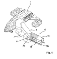
- Fig. 1
- zeigt in schematischer Darstellung eine perspektivische Ansicht auf ein Fluggasttreppenfahrzeug, dass eine frei auskragende Ladefläche zur Aufnahme einer Schutzeinrichtung aufweist;
- Fig. 2
- zeigt eine Seitenansicht auf das Fahrzeug gemäß
Fig. 1 ; - Fig. 3
- zeigt eine Darstellung gemäß
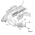
Fig. 1 , bei der die Ladefläche abgesenkt ist; - Fig. 4
- zeigt ein Fluggasttreppenfahrzeug mit frei auskragender Ladefläche, wobei die Laderfläche seitlich um 180° an dem Fluggasttreppenfahrzeug verschwenkbar angelenkt ist;
- Fig. 5
- zeigt eine Darstellung gemäß
Fig. 4 , bei der die einzelnen Tunnelelemente der Schutzeinrichtung bei abgesenkter und verschwenkter Position der Ladefläche zwecks Bildung eines Zugangstunnels auseinandergezogen sind; - Fig. 6
- zeigt ein Fluggasttreppenfahrzeug mit einem Anhänger, auf dem die Schutzeinrichtung umfassend mehrere Tunnelelemente lagert;
- Fig. 7
- zeigt ein Fluggasttreppenfahrzeug mit unter einer Treppeneinrichtung angeordneter Schutzreinrichtung mit mehreren Tunnelelementen;
- Fig. 8
- zeigt eine Darstellung gemäß
Fig. 7 , wobei das der Schutzeinrichtung zugewandte Ende der Treppeneinrichtung abgesenkt ist. - Gemäß den
Figuren 1 bis 5 ist das Flugzeug mit 1 bezeichnet. An dem Flugzeug 1 angedockt ist das Fluggasttreppenfahrzeug 3 mit der - Fluggasttreppe 5, wobei die Fluggasttreppe 5 den Zugang zum Flugzeug ermöglicht. Frei auskragend an dem Fluggasttreppenfahrzeug 3 angelenkt ist nach einer ersten Ausführungsform die mit 10 bezeichnete Ladefläche (
Fig. 1 bis Fig. 3 ). Die Ladefläche 10 nimmt die mit 12 bezeichnete Schutzeinrichtung auf, die mehrere Tunnelelemente 15 umfasst. Die Tunnelelemente 15, die konisch ausgebildet sind, können insofern teleskopartig ineinander gelagert auf der Ladefläche 10 angeordnet sein. Mithilfe der insgesamt mit 20 bezeichneten Hubeinrichtung kann die Ladefläche 10 auf den Boden abgesenkt werden (Fig. 3 ), um dann die einzelnen Tunnelelement 15 zur Bildung des Zugangstunnels auseinander zu fahren, wozu die einzelnen Tunnelelemente auf ihrer Unterseite Räder 15a aufweisen. Die Ladefläche 10 umfasst hierbei zwei parallel zueinander verlaufende Schienen. - Als Variante zu der ersten Ausführungsform ist gemäß den
Figuren 4 und5 vorgesehen, dass die Ladefläche 10 an dem Fluggasttreppenfahrzeug 3 horizontal verschwenkbar angelenkt ist, sodass diese sich, wie inFig. 5 dargestellt, nach Verschwenkung um 180° seitlich parallel zum Fluggasttreppenfahrzeug 3 befindet. In dieser Stellung wird dann die Ladefläche, die vollflächig abgebildet ist, abgesenkt, um die darauf befindlichen Tunnelelemente 15 zur Bildung des Zugangstunnels, beispielsweise zu einem Flughafenbus, auseinanderziehen zu können. Die Tunnelelemente sind auch hier, wie bereits zuvor erläutert, konisch ausgebildet und verfügen über Räder 15a. - Bei der zweiten Ausführungsform gemäß
Fig. 6 ist am Fluggasttreppenfahrzeug 3 ein Anhänger 17 angehängt, wobei der Anhänger 17 die Ladefläche 10 und das Fahrgestell 13 umfasst, wobei das Fahrgestell 13 absenkbar ausgebildet ist, sodass die Ladefläche 10 des Anhängers zumindest mit dem hinteren Ende auf dem Boden aufstehen kann, um die einzelnen Tunnelelemente 15 der Schutzeinrichtung 12 von der Ladefläche 10 verfahren zu können, wie dies bei der bereits abgehandelten Ausführungsform erläutert worden ist. - Um die einzelnen Tunnelelemente von der Ladefläche zur Bildung des Zugangstunnels auseinanderziehen zu können, ist vorteilhaft das vordere Tunnelelement auf der Ladefläche fixiert, beispielsweise durch Blockade der Räder 15a des Tunnelelements, das der Fluggasttreppe 5 unmittelbar zugewandt ist.
- Das mit 3 bezeichnete Fluggasttreppenfahrzeug umfasst nach der dritten Ausführungsform gemäß den
Figuren 7 und8 ebenfalls eine insbesondere absenkbare Ladefläche 10 zur Aufnahme der Schutzeinrichtung 12, umfassend eine Mehrzahl von Tunnelelementen 15. Das Fluggasttreppenfahrzeug 3 weist am hinteren Ende eine Hubvorrichtung 40 auf, wobei die Hubvorrichtung 40 zwei beabstandet zueinander angeordnete Hubsäulen 45 umfasst, die der Führung des hinteren, zugangsseitigen Endes der mit 30 bezeichneten Treppeneinrichtung dienen. Zur Aufnahme der Treppeneinrichtung 30 weist das Anschlusstreppensegment 34 zu beiden Seiten jeweils einen Nocken 35 auf, wobei ein jeder Nocken 35 durch eine Hubsäule 45 geführt ist. Zur Aufnahme des entsprechenden Nocken 35 ist die Hubsäule im Querschnitt etwa C-profilförmig ausgebildet. Das Anheben der Treppeneinrichtung 30 im hinteren Endbereich des Fahrzeugs kann z. B. durch Kolbenzylinderantriebe entweder hydraulisch oder pneumatisch bewirkt werden oder auch beispielsweise durch jeweils einen in jeder Hubsäule 45 angeordneten Kettentrieb. - Das Fluggasttreppenfahrzeug 3 weist des Weiteren im vorderen Ende den Bock 50 zur Lagerung des vorderen Endes der Treppeneinrichtung 30 auf. Der Bock 50 umfasst zu beiden Seiten des Fluggasttreppenfahrzeugs 3 angeordnete in der Länge veränderbare Teleskopstützen 52, die am oberen Ende durch eine Traverse 55 miteinander in Verbindung stehen. Die Traverse ist hierbei um eine horizontale Achse verschwenkbar an den Teleskopstützen gelagert. Auf der Traverse 55 liegt das vordere Ende der Treppeneinrichtung 30 auf. Die Teleskopstützen 52 weisen jeweils einen Stützarm 58 auf, der an einem Ende am Fluggasttreppenfahrzeug 3 angeordnet ist, und am anderen Ende an der Teleskopstütze 52. Die mit Treppen versehene Treppeneinrichtung 30, die getunnelt ist, weist das Anschlusstreppensegment 34 auf, dass ebenfalls Treppenstufen besitzt und gleichfalls getunnelt ist. In der Treppeneinrichtung ist das Anschlusstreppensegment 34 teleskopierbar gelagert. Das heißt, dass hierdurch die Treppeneinrichtung zur Anpassung an unterschiedliche Flugzeughöhen in der Länge veränderbar ist. Die Längenveränderung der Treppeneinrichtung wird hierbei durch Höhenverstellung des Bocks und/oder durch das Teleskopieren des Anschlusstreppensegments aus der Treppeneinrichtung heraus oder in diese herein bewirkt. Das Anschlusstreppensegment 34 zeigt darüber hinaus einen im abgesenkten Zustand der Treppeneinrichtung 30 im Wesentlichen lotrecht ausgerichteten Anschlussrahmen 37, der der Verbindung mit einem entsprechenden Rahmen eines Tunnelelementes 15 dient.
- Am vorderen Ende dem Flugzeug zugewandten Ende weist die Treppeneinrichtung 30 das Kuppelmodul 32 auf, das an seinem freien Ende ein nicht dargestelltes Faltenvordach aufweisen kann.
- Die Funktionsweise des erfindungsgemäßen Fluggasttreppenfahrzeugs 3 stellt sich nun wie folgt dar. In dem in
Fig. 7 dargestellten Zustand wird das Fluggasttreppenfahrzeug 3 an das Flugzeug herangefahren. Alsdann wird die Schutzeinrichtung 12 mit den einzelnen Tunnelelementen von der Ladefläche 10 des Fluggasttreppenfahrzeugs 3 herausgezogen. Hierzu kann die Ladefläche gegebenenfalls abgesenkt werden. Ist dies geschehen, so wird die Treppeneinrichtung 30 am hinteren Ende, also im Bereich des Anschlusstreppensegments an den beiden Hubsäulen 45 abgesenkt, bis eine Stellung gemäßFig. 8 erreicht ist. Alsdann kann das vordere Ende der Treppeneinrichtung 30 mit dem Kuppelmodul 32 mithilfe der Teleskopstützen 52 des Bockes 50 so weit angehoben werden, bis das Kuppelmodul 32 den Zugangsbereich des Flugzeugs erreicht. Sollte die zum Erreichen des Zugangs des Flugzeugs erforderliche Höhe durch die Treppeneinrichtung nicht erreichbar sein, so kann durch die Teleskopierbarkeit des Anschlusstreppensegments 34 der Treppeneinrichtung 30 die erforderliche Länge bereitgestellt werden. Das Auseinanderfahren des Anschlusstreppensegments 34 aus der Treppeneinrichtung 30 kann durch einen zwischen Treppeneinrichtung und Anschlusstreppensegment angeordneten Zahnstangentrieb oder Kettentrieb 36 bewerkstelligt werden. Alternativ kann sich ein solcher Zahnstangen- oder Kettentrieb auch zwischen der Traverse und der Treppeneinrichtung befinden. Um zu gewährleisten, dass die Traverse 55 an der Unterseite der Treppeneinrichtung vollflächig anliegen kann, wenn der Bock 50 in der Höhe verstellt wird, ist vorgesehen, dass die Traverse an eine horizontale Achse verschwenkbar mit den Teleskopstützen verbunden ist. -
- 1
- Flugzeug
- 3
- Fluggasttreppenfahrzeug
- 5
- Fluggasttreppe
- 10
- Ladefläche
- 12
- Schutzeinrichtung
- 13
- Fahrgestell
- 15
- Tunnelelement
- 15a
- Räder
- 17
- Anhänger
- 20
- Hubeinrichtung
- 30
- Treppeneinrichtung
- 32
- Kuppelmodul
- 34
- Anschlusssegment
- 35
- Nocken
- 36
- Kettentrieb/Zahnstangentrieb
- 37
- Anschlussrahmen
- 40
- Hubvorrichtung
- 45
- Hubsäule
- 50
- Bock
- 52
- Teleskopstützen
- 55
- Traverse
- 58
- Stützarm
Claims (21)
- Zugangseinrichtung zu einem Flugzeug (1), Bus oder Gebäude, umfassend eine mit einem Fahrzeug verbundene Ladefläche (10), wobei auf der Ladefläche (10) eine Schutzeinrichtung (12) für Passagiere angeordnet ist.
- Zugangseinrichtung zu einem Flugzeug (1), Bus oder Gebäude nach Anspruch 1,
dadurch gekennzeichnet,
dass das Fahrzeug als Fluggasttreppenfahrzeug (3) ausgebildet ist. - Zugangseinrichtung zu einem Flugzeug (1), Bus oder Gebäude nach einem der voranstehenden Ansprüche,
dadurch gekennzeichnet,
dass die Schutzeinrichtung (12) mindestens ein, vorzugsweise mehrere Tunnelelemente (15) umfasst. - Zugangseinrichtung zu einem Flugzeug (1), Bus oder Gebäude nach Anspruch 3,
dadurch gekennzeichnet,
dass das mindestens eine Tunnelelement (15) verfahrbar ist. - Zugangseinrichtung zu einem Flugzeug (1), Bus oder Gebäude nach Anspruch 4,
dadurch gekennzeichnet,
dass das mindestens eine Tunnelelement (15) zur Verfahrbarkeit Rollen (15a) aufweist. - Zugangseinrichtung zu einem Flugzeug (1), Bus oder Gebäude nach einem der Ansprüche 3 bis 5,
dadurch gekennzeichnet,
dass die Tunnelelemente (15) auf der Ladefläche (10) teleskopartig ineinander lagerbar sind. - Zugangseinrichtung zu einem Flugzeug (1), Bus oder Gebäude nach einem der voranstehenden Ansprüche,
dadurch gekennzeichnet,
dass die Ladefläche (10) an dem Fahrzeug horizontal verschwenkbar anbringbar ist. - Zugangseinrichtung zu einem Flugzeug (1), Bus oder Gebäude nach Anspruch 7,
dadurch gekennzeichnet,
dass die Ladefläche (10) um 180° verschwenkbar an dem Fahrzeug anbringbar ist. - Zugangseinrichtung zu einem Flugzeug (1), Bus oder Gebäude nach einem der voranstehenden Ansprüche,
dadurch gekennzeichnet,
dass die Ladefläche (10) absenkbar ist. - Zugangseinrichtung zu einem Flugzeug (1), Bus oder Gebäude nach einem der voranstehenden Ansprüche,
dadurch gekennzeichnet,
dass die Ladefläche (10) frei auskragend an dem Fahrzeug angeordnet ist. - Zugangseinrichtung zu einem Flugzeug (1), Bus oder Gebäude nach Anspruch 10,
dadurch gekennzeichnet,
dass die frei auskragende Ladefläche (10) durch eine Hubeinrichtung (20) absenkbar ist. - Zugangseinrichtung zu einem Flugzeug (1), Bus oder Gebäude nach einem der voranstehenden Ansprüche,
dadurch gekennzeichnet,
dass die Ladefläche (10) ein Fahrgestell (12) aufweist. - Zugangseinrichtung zu einem Flugzeug (1), Bus oder Gebäude nach Anspruch 12,
dadurch gekennzeichnet,
dass das Fahrgestell (12) die Ladefläche (10) absenkbar aufnimmt. - Zugangseinrichtung zu einem Flugzeug (1), Bus oder Gebäude nach Anspruch 3,
dadurch gekennzeichnet,
dass das vordere Tunnelelement (15) auf der Ladefläche (10) fixierbar ist. - Zugangseinrichtung zu einem Flugzeug (1), Bus oder Gebäude nach Anspruch 2,
dadurch gekennzeichnet,
dass das Fluggasttreppenfahrzeug (3) eine Treppeneinrichtung (30) aufweist, wobei die Treppeneinrichtung (30) unter Schaffung eines Freiraums über der Ladefläche (10) des Fluggasttreppenfahrzeugs (3) zumindest an einem Ende in der Höhe durch eine Hubvorrichtung (40) verstellbar ist. - Zugangseinrichtung zu einem Flugzeug (1), Bus oder Gebäude nach Anspruch 15,
dadurch gekennzeichnet,
dass die Hubvorrichtung (40) am hinteren Ende des Fluggasttreppenfahrzeugs (3) angeordnet ist. - Zugangseinrichtung zu einem Flugzeug (1), Bus oder Gebäude nach Anspruch 15 oder 16,
dadurch gekennzeichnet,
dass die Treppeneinrichtung (30) im Bereich des vorderen Endes des Fluggasttreppenfahrzeugs (3) auf einem Bock (50) aufsitzt, wobei auf dem Bock (50) die Treppeneinrichtung (30) verschieblich angeordnet ist, wobei der Bock (50) in der Höhe verstellbar ist. - Zugangseinrichtung zu einem Flugzeug (1), Bus oder Gebäude nach einem der Ansprüche 15 bis 17,
dadurch gekennzeichnet,
dass die Treppeneinrichtung (30) im Bereich des hinteren Endes im abgesenkten Zustand des hinteren Bereichs der Treppeneinrichtung (30) einen im Wesentlichen lotrechten Anschlussrahmen (37) aufweist. - Zugangseinrichtung zu einem Flugzeug (1), Bus oder Gebäude nach Anspruch 18,
dadurch gekennzeichnet,
dass die Treppeneinrichtung (30) im hinteren absenkbaren Endbereich ein Anschlusstreppensegment (34) aufweist, wobei die Treppeneinrichtung das Anschlusstreppensegment (34) teleskopierbar aufnimmt. - Zugangseinrichtung zu einem Flugzeug (1), Bus oder Gebäude nach einem der Ansprüche 18 und 19,
dadurch gekennzeichnet,
dass die Treppeneinrichtung (30) und/oder das Anschlusstreppensegment (34) getunnelt ist. - Zugangseinrichtung zu einem Flugzeug (1), Bus oder Gebäude nach einem der Ansprüche 15 bis 20,
dadurch gekennzeichnet,
dass die Hubvorrichtung (40) zwei Hubsäulen (45) umfasst, durch die die Treppeneinrichtung (30) in der Höhe verstellbar verschieblich geführt ist.
Priority Applications (2)
| Application Number | Priority Date | Filing Date | Title |
|---|---|---|---|
| US15/424,400 US9969506B2 (en) | 2016-02-04 | 2017-02-03 | Access device to an airplane |
| CN201710063543.1A CN107031862B (zh) | 2016-02-04 | 2017-02-03 | 进入飞机的进入设备 |
Applications Claiming Priority (1)
| Application Number | Priority Date | Filing Date | Title |
|---|---|---|---|
| DE102016001273.0A DE102016001273A1 (de) | 2016-02-04 | 2016-02-04 | Zugangseinrichtung zu einem Flugzeug |
Publications (2)
| Publication Number | Publication Date |
|---|---|
| EP3202668A1 true EP3202668A1 (de) | 2017-08-09 |
| EP3202668B1 EP3202668B1 (de) | 2020-11-04 |
Family
ID=56883715
Family Applications (1)
| Application Number | Title | Priority Date | Filing Date |
|---|---|---|---|
| EP16187620.6A Active EP3202668B1 (de) | 2016-02-04 | 2016-09-07 | Zugangseinrichtung zu einem flugzeug |
Country Status (5)
| Country | Link |
|---|---|
| US (1) | US9969506B2 (de) |
| EP (1) | EP3202668B1 (de) |
| CN (1) | CN107031862B (de) |
| DE (1) | DE102016001273A1 (de) |
| ES (1) | ES2833363T3 (de) |
Cited By (2)
| Publication number | Priority date | Publication date | Assignee | Title |
|---|---|---|---|---|
| EP3395691A1 (de) * | 2017-04-25 | 2018-10-31 | thyssenkrupp Airport Solutions S.A. | Vorfeldtor an einem flughafen |
| EP3202667B1 (de) * | 2016-02-05 | 2019-10-09 | Hübner GmbH & Co. KG | Zugangstunnelsystem zur überdachten führung von personen |
Families Citing this family (1)
| Publication number | Priority date | Publication date | Assignee | Title |
|---|---|---|---|---|
| CN111470062A (zh) * | 2020-06-01 | 2020-07-31 | 民航机场规划设计研究总院有限公司 | 一种登机厅 |
Citations (6)
| Publication number | Priority date | Publication date | Assignee | Title |
|---|---|---|---|---|
| FR921163A (fr) * | 1945-10-31 | 1947-04-29 | Système de couloir articulé d'accès aux avions | |
| EP0256976A2 (de) * | 1986-08-14 | 1988-02-24 | Gebrüder Frech AG | Fahrbare Flugzeugtreppe |
| DE8815054U1 (de) * | 1988-12-02 | 1989-01-26 | Hamburger Hochbahn Ag, 2000 Hamburg | Teleskopierbare Fahrtreppe, insbesondere Flugfeldtreppe |
| WO2001088287A1 (en) | 2000-05-16 | 2001-11-22 | Roman Arseniuk | Liquid dispenser |
| FR2886624A1 (fr) | 2005-06-02 | 2006-12-08 | Air France Sa Soc | Equipement de securite pour tunnel de transfert de passagers et tunnel comportant un tel equipement |
| EP2003086A2 (de) * | 2006-02-07 | 2008-12-17 | TCM Corporation | Einstieg und ausstieg für passagierfahrzeuge |
Family Cites Families (18)
| Publication number | Priority date | Publication date | Assignee | Title |
|---|---|---|---|---|
| US2470337A (en) * | 1947-01-20 | 1949-05-17 | Richard L Campbell | Extensible canopy |
| US3046850A (en) * | 1958-03-10 | 1962-07-31 | Clair W Tellefson | Foldable walkway and storage apparatus therefor |
| US3048680A (en) | 1960-10-07 | 1962-08-07 | Mc Graw Edison Co | Fuse cutout |
| US3524563A (en) * | 1968-05-24 | 1970-08-18 | Cochran Western Corp | Mobile loading apparatus |
| US4517698A (en) * | 1983-01-05 | 1985-05-21 | Lamp L Thomas A | Cargo handling ramp |
| US5040257A (en) * | 1990-06-13 | 1991-08-20 | Bentz Carl I | Aircraft loading bridge extender |
| FR2667045B1 (fr) * | 1990-09-20 | 1995-03-10 | Montier Robert | Dispositif mobile et telescopique pour couvrir le cheminement des passagers entre un local et un aeronef. |
| US5603343A (en) * | 1995-02-03 | 1997-02-18 | James Larson | Passageway for loading and unloading aircraft |
| US7069611B2 (en) * | 2000-05-12 | 2006-07-04 | Infra-Structures, Inc | Regional boarding ramp for commuter aircraft |
| US6526615B1 (en) * | 2002-02-01 | 2003-03-04 | Dew Engineering And Development Limited | Flexible over the wing passenger loading bridge |
| US7039978B2 (en) * | 2002-02-01 | 2006-05-09 | Dew Engineering And Development Limited | Flexible over the wing passenger loading bridge |
| DE102004016272B4 (de) * | 2004-04-02 | 2006-08-17 | Hübner GmbH | Fluggasttreppe oder Fluggastbrücke |
| CN201678049U (zh) * | 2010-01-11 | 2010-12-22 | 蒂森克虏伯机场系统(中山)有限公司 | 一种改进的登机桥 |
| DE202012008839U1 (de) | 2012-09-14 | 2012-10-31 | Hübner GmbH | Zugangstunnel zu einem Flugzeug |
| JP6250796B2 (ja) * | 2013-06-03 | 2017-12-20 | イースト アイランド アビエーション サービスィズ インコーポレイテッド | ボーディングブリッジと敷居の低い飛行機をインタフェースする装置 |
| FR3018504B1 (fr) * | 2014-03-13 | 2017-10-13 | Sominex | Dispositif deployable pour couvrir le cheminement des passagers entre un batiment terminal et un moyen de transport par exemple aerien |
| US9238512B1 (en) * | 2014-03-24 | 2016-01-19 | William Floyd Keith | Portable passenger boarding ramp assembly |
| CN204281147U (zh) * | 2014-12-04 | 2015-04-22 | 刘强 | 一种伸缩套筒装置 |
-
2016
- 2016-02-04 DE DE102016001273.0A patent/DE102016001273A1/de not_active Ceased
- 2016-09-07 ES ES16187620T patent/ES2833363T3/es active Active
- 2016-09-07 EP EP16187620.6A patent/EP3202668B1/de active Active
-
2017
- 2017-02-03 US US15/424,400 patent/US9969506B2/en active Active
- 2017-02-03 CN CN201710063543.1A patent/CN107031862B/zh not_active Expired - Fee Related
Patent Citations (6)
| Publication number | Priority date | Publication date | Assignee | Title |
|---|---|---|---|---|
| FR921163A (fr) * | 1945-10-31 | 1947-04-29 | Système de couloir articulé d'accès aux avions | |
| EP0256976A2 (de) * | 1986-08-14 | 1988-02-24 | Gebrüder Frech AG | Fahrbare Flugzeugtreppe |
| DE8815054U1 (de) * | 1988-12-02 | 1989-01-26 | Hamburger Hochbahn Ag, 2000 Hamburg | Teleskopierbare Fahrtreppe, insbesondere Flugfeldtreppe |
| WO2001088287A1 (en) | 2000-05-16 | 2001-11-22 | Roman Arseniuk | Liquid dispenser |
| FR2886624A1 (fr) | 2005-06-02 | 2006-12-08 | Air France Sa Soc | Equipement de securite pour tunnel de transfert de passagers et tunnel comportant un tel equipement |
| EP2003086A2 (de) * | 2006-02-07 | 2008-12-17 | TCM Corporation | Einstieg und ausstieg für passagierfahrzeuge |
Cited By (3)
| Publication number | Priority date | Publication date | Assignee | Title |
|---|---|---|---|---|
| EP3202667B1 (de) * | 2016-02-05 | 2019-10-09 | Hübner GmbH & Co. KG | Zugangstunnelsystem zur überdachten führung von personen |
| EP3395691A1 (de) * | 2017-04-25 | 2018-10-31 | thyssenkrupp Airport Solutions S.A. | Vorfeldtor an einem flughafen |
| WO2018197449A1 (en) * | 2017-04-25 | 2018-11-01 | thyssenkrupp Airport Solutions, S.A. | Apron gate at an airport |
Also Published As
| Publication number | Publication date |
|---|---|
| US20170225803A1 (en) | 2017-08-10 |
| CN107031862B (zh) | 2021-03-23 |
| ES2833363T3 (es) | 2021-06-15 |
| EP3202668B1 (de) | 2020-11-04 |
| DE102016001273A1 (de) | 2017-08-10 |
| CN107031862A (zh) | 2017-08-11 |
| US9969506B2 (en) | 2018-05-15 |
Similar Documents
| Publication | Publication Date | Title |
|---|---|---|
| EP0865539B1 (de) | Vorrichtung zur brückeninspektion | |
| EP3202668B1 (de) | Zugangseinrichtung zu einem flugzeug | |
| DE3332227C2 (de) | Brückenuntersichtgerät | |
| WO1991003603A1 (de) | Brückenuntersichtvorrichtung | |
| DE1848387U (de) | Zum einbau in eine garage zum abstellen zweier kraftfahrzeuge uebereinander bestimmte vorrichtung. | |
| DE2644022C2 (de) | Vorrichtung zum Abstellen von Fahrzeugen auf mindestens zwei übereinander angeordneten Plattformen | |
| WO2014040584A1 (de) | Zugangstunnel zu einem flugzeug | |
| DE102012104056A1 (de) | Ladelift für eine Ladeplattform | |
| DE102005024585A1 (de) | Drehleiter für Rettungsfahrzeuge | |
| EP3988395B1 (de) | Nivellierbarer dachzeltträger für einen personenwagen | |
| EP0018486A1 (de) | Versorgungsfahrzeug mit hydraulisch anhebbarer Wechselplattform, insbesondere für den Flughafenbetrieb | |
| DE10135748C1 (de) | Vorrichtung und Verfahren zur Herstellung einer bewehrten Betoninnenschale eines Tunnels | |
| DE2138717C3 (de) | Steckenvortriebsmaschine mit provisorischem Ausbau | |
| DE19911882C1 (de) | Ortsfeste Fluggastbrücke | |
| EP1616778B1 (de) | Fahrzeug zum Transport überbreiter Güter | |
| DE202015002163U1 (de) | Arbeitsbühne | |
| EP0118586A2 (de) | Container-Fahrzeug | |
| DE69206066T2 (de) | Einziehbares Geländer für Strassenkraftfahrzeugtransporter. | |
| DE10394150T5 (de) | Nachgiebige Passagier-Verladebrücke zur Anordnung über dem Flügel eines Flugzeuges | |
| DE19620511A1 (de) | Verfahren und Vorrichtung zum Verlegen von Brücken | |
| EP4509460B1 (de) | Arbeitsbühne für verladeeinrichtungen | |
| EP3699121B1 (de) | Zugangssystem für eisenbahnkesselwagen, verschubwagen und verfahren zum bereitstellen eines zugangs | |
| DE102009026061B4 (de) | Schwenkbare Dacharbeitsbühne | |
| DE4400741A1 (de) | Fahrzeug zum Evakuieren von Personen aus Flugzeugen | |
| DE3426162A1 (de) | Fahrzeug zum transport von fertiggaragen |
Legal Events
| Date | Code | Title | Description |
|---|---|---|---|
| PUAI | Public reference made under article 153(3) epc to a published international application that has entered the european phase |
Free format text: ORIGINAL CODE: 0009012 |
|
| STAA | Information on the status of an ep patent application or granted ep patent |
Free format text: STATUS: THE APPLICATION HAS BEEN PUBLISHED |
|
| AK | Designated contracting states |
Kind code of ref document: A1 Designated state(s): AL AT BE BG CH CY CZ DE DK EE ES FI FR GB GR HR HU IE IS IT LI LT LU LV MC MK MT NL NO PL PT RO RS SE SI SK SM TR |
|
| AX | Request for extension of the european patent |
Extension state: BA ME |
|
| STAA | Information on the status of an ep patent application or granted ep patent |
Free format text: STATUS: REQUEST FOR EXAMINATION WAS MADE |
|
| 17P | Request for examination filed |
Effective date: 20170807 |
|
| RBV | Designated contracting states (corrected) |
Designated state(s): AL AT BE BG CH CY CZ DE DK EE ES FI FR GB GR HR HU IE IS IT LI LT LU LV MC MK MT NL NO PL PT RO RS SE SI SK SM TR |
|
| STAA | Information on the status of an ep patent application or granted ep patent |
Free format text: STATUS: EXAMINATION IS IN PROGRESS |
|
| 17Q | First examination report despatched |
Effective date: 20190410 |
|
| GRAP | Despatch of communication of intention to grant a patent |
Free format text: ORIGINAL CODE: EPIDOSNIGR1 |
|
| STAA | Information on the status of an ep patent application or granted ep patent |
Free format text: STATUS: GRANT OF PATENT IS INTENDED |
|
| INTG | Intention to grant announced |
Effective date: 20200508 |
|
| GRAS | Grant fee paid |
Free format text: ORIGINAL CODE: EPIDOSNIGR3 |
|
| GRAA | (expected) grant |
Free format text: ORIGINAL CODE: 0009210 |
|
| STAA | Information on the status of an ep patent application or granted ep patent |
Free format text: STATUS: THE PATENT HAS BEEN GRANTED |
|
| AK | Designated contracting states |
Kind code of ref document: B1 Designated state(s): AL AT BE BG CH CY CZ DE DK EE ES FI FR GB GR HR HU IE IS IT LI LT LU LV MC MK MT NL NO PL PT RO RS SE SI SK SM TR |
|
| REG | Reference to a national code |
Ref country code: GB Ref legal event code: FG4D Free format text: NOT ENGLISH |
|
| REG | Reference to a national code |
Ref country code: CH Ref legal event code: EP |
|
| REG | Reference to a national code |
Ref country code: AT Ref legal event code: REF Ref document number: 1330526 Country of ref document: AT Kind code of ref document: T Effective date: 20201115 |
|
| REG | Reference to a national code |
Ref country code: IE Ref legal event code: FG4D Free format text: LANGUAGE OF EP DOCUMENT: GERMAN |
|
| REG | Reference to a national code |
Ref country code: DE Ref legal event code: R096 Ref document number: 502016011593 Country of ref document: DE |
|
| REG | Reference to a national code |
Ref country code: NL Ref legal event code: MP Effective date: 20201104 |
|
| PG25 | Lapsed in a contracting state [announced via postgrant information from national office to epo] |
Ref country code: GR Free format text: LAPSE BECAUSE OF FAILURE TO SUBMIT A TRANSLATION OF THE DESCRIPTION OR TO PAY THE FEE WITHIN THE PRESCRIBED TIME-LIMIT Effective date: 20210205 Ref country code: FI Free format text: LAPSE BECAUSE OF FAILURE TO SUBMIT A TRANSLATION OF THE DESCRIPTION OR TO PAY THE FEE WITHIN THE PRESCRIBED TIME-LIMIT Effective date: 20201104 Ref country code: RS Free format text: LAPSE BECAUSE OF FAILURE TO SUBMIT A TRANSLATION OF THE DESCRIPTION OR TO PAY THE FEE WITHIN THE PRESCRIBED TIME-LIMIT Effective date: 20201104 Ref country code: PT Free format text: LAPSE BECAUSE OF FAILURE TO SUBMIT A TRANSLATION OF THE DESCRIPTION OR TO PAY THE FEE WITHIN THE PRESCRIBED TIME-LIMIT Effective date: 20210304 Ref country code: NO Free format text: LAPSE BECAUSE OF FAILURE TO SUBMIT A TRANSLATION OF THE DESCRIPTION OR TO PAY THE FEE WITHIN THE PRESCRIBED TIME-LIMIT Effective date: 20210204 |
|
| PG25 | Lapsed in a contracting state [announced via postgrant information from national office to epo] |
Ref country code: SE Free format text: LAPSE BECAUSE OF FAILURE TO SUBMIT A TRANSLATION OF THE DESCRIPTION OR TO PAY THE FEE WITHIN THE PRESCRIBED TIME-LIMIT Effective date: 20201104 Ref country code: BG Free format text: LAPSE BECAUSE OF FAILURE TO SUBMIT A TRANSLATION OF THE DESCRIPTION OR TO PAY THE FEE WITHIN THE PRESCRIBED TIME-LIMIT Effective date: 20210204 Ref country code: IS Free format text: LAPSE BECAUSE OF FAILURE TO SUBMIT A TRANSLATION OF THE DESCRIPTION OR TO PAY THE FEE WITHIN THE PRESCRIBED TIME-LIMIT Effective date: 20210304 Ref country code: PL Free format text: LAPSE BECAUSE OF FAILURE TO SUBMIT A TRANSLATION OF THE DESCRIPTION OR TO PAY THE FEE WITHIN THE PRESCRIBED TIME-LIMIT Effective date: 20201104 Ref country code: LV Free format text: LAPSE BECAUSE OF FAILURE TO SUBMIT A TRANSLATION OF THE DESCRIPTION OR TO PAY THE FEE WITHIN THE PRESCRIBED TIME-LIMIT Effective date: 20201104 |
|
| REG | Reference to a national code |
Ref country code: LT Ref legal event code: MG9D |
|
| REG | Reference to a national code |
Ref country code: ES Ref legal event code: FG2A Ref document number: 2833363 Country of ref document: ES Kind code of ref document: T3 Effective date: 20210615 |
|
| PG25 | Lapsed in a contracting state [announced via postgrant information from national office to epo] |
Ref country code: HR Free format text: LAPSE BECAUSE OF FAILURE TO SUBMIT A TRANSLATION OF THE DESCRIPTION OR TO PAY THE FEE WITHIN THE PRESCRIBED TIME-LIMIT Effective date: 20201104 |
|
| PG25 | Lapsed in a contracting state [announced via postgrant information from national office to epo] |
Ref country code: SK Free format text: LAPSE BECAUSE OF FAILURE TO SUBMIT A TRANSLATION OF THE DESCRIPTION OR TO PAY THE FEE WITHIN THE PRESCRIBED TIME-LIMIT Effective date: 20201104 Ref country code: RO Free format text: LAPSE BECAUSE OF FAILURE TO SUBMIT A TRANSLATION OF THE DESCRIPTION OR TO PAY THE FEE WITHIN THE PRESCRIBED TIME-LIMIT Effective date: 20201104 Ref country code: CZ Free format text: LAPSE BECAUSE OF FAILURE TO SUBMIT A TRANSLATION OF THE DESCRIPTION OR TO PAY THE FEE WITHIN THE PRESCRIBED TIME-LIMIT Effective date: 20201104 Ref country code: EE Free format text: LAPSE BECAUSE OF FAILURE TO SUBMIT A TRANSLATION OF THE DESCRIPTION OR TO PAY THE FEE WITHIN THE PRESCRIBED TIME-LIMIT Effective date: 20201104 Ref country code: SM Free format text: LAPSE BECAUSE OF FAILURE TO SUBMIT A TRANSLATION OF THE DESCRIPTION OR TO PAY THE FEE WITHIN THE PRESCRIBED TIME-LIMIT Effective date: 20201104 Ref country code: LT Free format text: LAPSE BECAUSE OF FAILURE TO SUBMIT A TRANSLATION OF THE DESCRIPTION OR TO PAY THE FEE WITHIN THE PRESCRIBED TIME-LIMIT Effective date: 20201104 |
|
| REG | Reference to a national code |
Ref country code: DE Ref legal event code: R097 Ref document number: 502016011593 Country of ref document: DE |
|
| PG25 | Lapsed in a contracting state [announced via postgrant information from national office to epo] |
Ref country code: DK Free format text: LAPSE BECAUSE OF FAILURE TO SUBMIT A TRANSLATION OF THE DESCRIPTION OR TO PAY THE FEE WITHIN THE PRESCRIBED TIME-LIMIT Effective date: 20201104 |
|
| PLBE | No opposition filed within time limit |
Free format text: ORIGINAL CODE: 0009261 |
|
| STAA | Information on the status of an ep patent application or granted ep patent |
Free format text: STATUS: NO OPPOSITION FILED WITHIN TIME LIMIT |
|
| 26N | No opposition filed |
Effective date: 20210805 |
|
| PG25 | Lapsed in a contracting state [announced via postgrant information from national office to epo] |
Ref country code: NL Free format text: LAPSE BECAUSE OF FAILURE TO SUBMIT A TRANSLATION OF THE DESCRIPTION OR TO PAY THE FEE WITHIN THE PRESCRIBED TIME-LIMIT Effective date: 20201104 Ref country code: AL Free format text: LAPSE BECAUSE OF FAILURE TO SUBMIT A TRANSLATION OF THE DESCRIPTION OR TO PAY THE FEE WITHIN THE PRESCRIBED TIME-LIMIT Effective date: 20201104 |
|
| PG25 | Lapsed in a contracting state [announced via postgrant information from national office to epo] |
Ref country code: SI Free format text: LAPSE BECAUSE OF FAILURE TO SUBMIT A TRANSLATION OF THE DESCRIPTION OR TO PAY THE FEE WITHIN THE PRESCRIBED TIME-LIMIT Effective date: 20201104 |
|
| REG | Reference to a national code |
Ref country code: BE Ref legal event code: MM Effective date: 20210930 |
|
| PG25 | Lapsed in a contracting state [announced via postgrant information from national office to epo] |
Ref country code: IS Free format text: LAPSE BECAUSE OF FAILURE TO SUBMIT A TRANSLATION OF THE DESCRIPTION OR TO PAY THE FEE WITHIN THE PRESCRIBED TIME-LIMIT Effective date: 20210304 Ref country code: MC Free format text: LAPSE BECAUSE OF FAILURE TO SUBMIT A TRANSLATION OF THE DESCRIPTION OR TO PAY THE FEE WITHIN THE PRESCRIBED TIME-LIMIT Effective date: 20201104 |
|
| PG25 | Lapsed in a contracting state [announced via postgrant information from national office to epo] |
Ref country code: LU Free format text: LAPSE BECAUSE OF NON-PAYMENT OF DUE FEES Effective date: 20210907 Ref country code: IE Free format text: LAPSE BECAUSE OF NON-PAYMENT OF DUE FEES Effective date: 20210907 Ref country code: BE Free format text: LAPSE BECAUSE OF NON-PAYMENT OF DUE FEES Effective date: 20210930 |
|
| PGFP | Annual fee paid to national office [announced via postgrant information from national office to epo] |
Ref country code: GB Payment date: 20220927 Year of fee payment: 7 Ref country code: DE Payment date: 20220920 Year of fee payment: 7 Ref country code: AT Payment date: 20220919 Year of fee payment: 7 |
|
| PGFP | Annual fee paid to national office [announced via postgrant information from national office to epo] |
Ref country code: FR Payment date: 20220920 Year of fee payment: 7 |
|
| PGFP | Annual fee paid to national office [announced via postgrant information from national office to epo] |
Ref country code: IT Payment date: 20220930 Year of fee payment: 7 Ref country code: ES Payment date: 20221018 Year of fee payment: 7 |
|
| PGFP | Annual fee paid to national office [announced via postgrant information from national office to epo] |
Ref country code: CH Payment date: 20220928 Year of fee payment: 7 |
|
| PG25 | Lapsed in a contracting state [announced via postgrant information from national office to epo] |
Ref country code: HU Free format text: LAPSE BECAUSE OF FAILURE TO SUBMIT A TRANSLATION OF THE DESCRIPTION OR TO PAY THE FEE WITHIN THE PRESCRIBED TIME-LIMIT; INVALID AB INITIO Effective date: 20160907 |
|
| PG25 | Lapsed in a contracting state [announced via postgrant information from national office to epo] |
Ref country code: CY Free format text: LAPSE BECAUSE OF FAILURE TO SUBMIT A TRANSLATION OF THE DESCRIPTION OR TO PAY THE FEE WITHIN THE PRESCRIBED TIME-LIMIT Effective date: 20201104 |
|
| REG | Reference to a national code |
Ref country code: DE Ref legal event code: R119 Ref document number: 502016011593 Country of ref document: DE |
|
| PG25 | Lapsed in a contracting state [announced via postgrant information from national office to epo] |
Ref country code: MK Free format text: LAPSE BECAUSE OF FAILURE TO SUBMIT A TRANSLATION OF THE DESCRIPTION OR TO PAY THE FEE WITHIN THE PRESCRIBED TIME-LIMIT Effective date: 20201104 |
|
| REG | Reference to a national code |
Ref country code: CH Ref legal event code: PL |
|
| REG | Reference to a national code |
Ref country code: AT Ref legal event code: MM01 Ref document number: 1330526 Country of ref document: AT Kind code of ref document: T Effective date: 20230907 |
|
| GBPC | Gb: european patent ceased through non-payment of renewal fee |
Effective date: 20230907 |
|
| PG25 | Lapsed in a contracting state [announced via postgrant information from national office to epo] |
Ref country code: GB Free format text: LAPSE BECAUSE OF NON-PAYMENT OF DUE FEES Effective date: 20230907 |
|
| PG25 | Lapsed in a contracting state [announced via postgrant information from national office to epo] |
Ref country code: CH Free format text: LAPSE BECAUSE OF NON-PAYMENT OF DUE FEES Effective date: 20230930 |
|
| PG25 | Lapsed in a contracting state [announced via postgrant information from national office to epo] |
Ref country code: AT Free format text: LAPSE BECAUSE OF NON-PAYMENT OF DUE FEES Effective date: 20230907 |
|
| PG25 | Lapsed in a contracting state [announced via postgrant information from national office to epo] |
Ref country code: GB Free format text: LAPSE BECAUSE OF NON-PAYMENT OF DUE FEES Effective date: 20230907 Ref country code: FR Free format text: LAPSE BECAUSE OF NON-PAYMENT OF DUE FEES Effective date: 20230930 Ref country code: DE Free format text: LAPSE BECAUSE OF NON-PAYMENT OF DUE FEES Effective date: 20240403 Ref country code: CH Free format text: LAPSE BECAUSE OF NON-PAYMENT OF DUE FEES Effective date: 20230930 Ref country code: AT Free format text: LAPSE BECAUSE OF NON-PAYMENT OF DUE FEES Effective date: 20230907 |
|
| PG25 | Lapsed in a contracting state [announced via postgrant information from national office to epo] |
Ref country code: MT Free format text: LAPSE BECAUSE OF FAILURE TO SUBMIT A TRANSLATION OF THE DESCRIPTION OR TO PAY THE FEE WITHIN THE PRESCRIBED TIME-LIMIT Effective date: 20201104 |
|
| REG | Reference to a national code |
Ref country code: ES Ref legal event code: FD2A Effective date: 20241028 |
|
| PG25 | Lapsed in a contracting state [announced via postgrant information from national office to epo] |
Ref country code: IT Free format text: LAPSE BECAUSE OF NON-PAYMENT OF DUE FEES Effective date: 20230907 |
|
| PG25 | Lapsed in a contracting state [announced via postgrant information from national office to epo] |
Ref country code: IT Free format text: LAPSE BECAUSE OF NON-PAYMENT OF DUE FEES Effective date: 20230907 |
|
| PG25 | Lapsed in a contracting state [announced via postgrant information from national office to epo] |
Ref country code: ES Free format text: LAPSE BECAUSE OF NON-PAYMENT OF DUE FEES Effective date: 20230908 |
|
| PG25 | Lapsed in a contracting state [announced via postgrant information from national office to epo] |
Ref country code: ES Free format text: LAPSE BECAUSE OF NON-PAYMENT OF DUE FEES Effective date: 20230908 |
|
| PG25 | Lapsed in a contracting state [announced via postgrant information from national office to epo] |
Ref country code: TR Free format text: LAPSE BECAUSE OF FAILURE TO SUBMIT A TRANSLATION OF THE DESCRIPTION OR TO PAY THE FEE WITHIN THE PRESCRIBED TIME-LIMIT Effective date: 20201104 |