EP3202680B1 - Plateau servant à maintenir et présenter des articles et procédé pour ouvrir et placer un tel plateau sur une étagère - Google Patents
Plateau servant à maintenir et présenter des articles et procédé pour ouvrir et placer un tel plateau sur une étagère Download PDFInfo
- Publication number
- EP3202680B1 EP3202680B1 EP17150101.8A EP17150101A EP3202680B1 EP 3202680 B1 EP3202680 B1 EP 3202680B1 EP 17150101 A EP17150101 A EP 17150101A EP 3202680 B1 EP3202680 B1 EP 3202680B1
- Authority
- EP
- European Patent Office
- Prior art keywords
- side wall
- wall
- tray
- bottom part
- cover part
- Prior art date
- Legal status (The legal status is an assumption and is not a legal conclusion. Google has not performed a legal analysis and makes no representation as to the accuracy of the status listed.)
- Active
Links
Images
Classifications
-
- B—PERFORMING OPERATIONS; TRANSPORTING
- B65—CONVEYING; PACKING; STORING; HANDLING THIN OR FILAMENTARY MATERIAL
- B65D—CONTAINERS FOR STORAGE OR TRANSPORT OF ARTICLES OR MATERIALS, e.g. BAGS, BARRELS, BOTTLES, BOXES, CANS, CARTONS, CRATES, DRUMS, JARS, TANKS, HOPPERS, FORWARDING CONTAINERS; ACCESSORIES, CLOSURES, OR FITTINGS THEREFOR; PACKAGING ELEMENTS; PACKAGES
- B65D5/00—Rigid or semi-rigid containers of polygonal cross-section, e.g. boxes, cartons or trays, formed by folding or erecting one or more blanks made of paper
- B65D5/20—Rigid or semi-rigid containers of polygonal cross-section, e.g. boxes, cartons or trays, formed by folding or erecting one or more blanks made of paper by folding-up portions connected to a central panel from all sides to form a container body, e.g. of tray-like form
- B65D5/2038—Rigid or semi-rigid containers of polygonal cross-section, e.g. boxes, cartons or trays, formed by folding or erecting one or more blanks made of paper by folding-up portions connected to a central panel from all sides to form a container body, e.g. of tray-like form at least two opposed folded-up portions having a non-rectangular shape
-
- B—PERFORMING OPERATIONS; TRANSPORTING
- B65—CONVEYING; PACKING; STORING; HANDLING THIN OR FILAMENTARY MATERIAL
- B65D—CONTAINERS FOR STORAGE OR TRANSPORT OF ARTICLES OR MATERIALS, e.g. BAGS, BARRELS, BOTTLES, BOXES, CANS, CARTONS, CRATES, DRUMS, JARS, TANKS, HOPPERS, FORWARDING CONTAINERS; ACCESSORIES, CLOSURES, OR FITTINGS THEREFOR; PACKAGING ELEMENTS; PACKAGES
- B65D5/00—Rigid or semi-rigid containers of polygonal cross-section, e.g. boxes, cartons or trays, formed by folding or erecting one or more blanks made of paper
- B65D5/32—Rigid or semi-rigid containers of polygonal cross-section, e.g. boxes, cartons or trays, formed by folding or erecting one or more blanks made of paper having bodies formed by folding and interconnecting two or more blanks
- B65D5/321—Rigid or semi-rigid containers of polygonal cross-section, e.g. boxes, cartons or trays, formed by folding or erecting one or more blanks made of paper having bodies formed by folding and interconnecting two or more blanks at least one container body part formed by folding up portions of a single blank connected to a central panel from all sides
-
- B—PERFORMING OPERATIONS; TRANSPORTING
- B65—CONVEYING; PACKING; STORING; HANDLING THIN OR FILAMENTARY MATERIAL
- B65D—CONTAINERS FOR STORAGE OR TRANSPORT OF ARTICLES OR MATERIALS, e.g. BAGS, BARRELS, BOTTLES, BOXES, CANS, CARTONS, CRATES, DRUMS, JARS, TANKS, HOPPERS, FORWARDING CONTAINERS; ACCESSORIES, CLOSURES, OR FITTINGS THEREFOR; PACKAGING ELEMENTS; PACKAGES
- B65D5/00—Rigid or semi-rigid containers of polygonal cross-section, e.g. boxes, cartons or trays, formed by folding or erecting one or more blanks made of paper
- B65D5/42—Details of containers or of foldable or erectable container blanks
- B65D5/54—Lines of weakness to facilitate opening of container or dividing it into separate parts by cutting or tearing
-
- B—PERFORMING OPERATIONS; TRANSPORTING
- B65—CONVEYING; PACKING; STORING; HANDLING THIN OR FILAMENTARY MATERIAL
- B65D—CONTAINERS FOR STORAGE OR TRANSPORT OF ARTICLES OR MATERIALS, e.g. BAGS, BARRELS, BOTTLES, BOXES, CANS, CARTONS, CRATES, DRUMS, JARS, TANKS, HOPPERS, FORWARDING CONTAINERS; ACCESSORIES, CLOSURES, OR FITTINGS THEREFOR; PACKAGING ELEMENTS; PACKAGES
- B65D5/00—Rigid or semi-rigid containers of polygonal cross-section, e.g. boxes, cartons or trays, formed by folding or erecting one or more blanks made of paper
- B65D5/42—Details of containers or of foldable or erectable container blanks
- B65D5/64—Lids
- B65D5/68—Telescope flanged lids
Definitions
- the invention relates to a tray for holding and displaying articles suitable for use at the place of sale, for example in retail shops.
- the tray is in particular suitable for use in a pushfeed system.
- the invention further relates to a method to open and place such a tray onto the display shelves, more particularly on a pushfeed system at the place of sale.
- trays generally made of cardboard to store and transport articles from the manufacturing location to the place of sale.
- a tray for holding and displaying articles is formed from at least one blank made of corrugated cardboard which is suitably cut, scored and folded to produce a box, generally a rectangular shaped box.
- Shelf Ready Packaging is the term used to refer to a product that comes in a ready merchandised unit to the place of sale.
- the Shelf Ready Packaging is preferably easy to identify, easy to open, can easily be put onto the shelf and can be easily be disposed of.
- Shelf Ready Packaging normally includes a cover part which can be removed from a bottom part, for example by tearing away the cover part from the bottom part.
- the packaging can be provided with a tear strip or with a tear line, for example a perforated tear line.
- the trays have sufficient stability to avoid collapsing and/or breaking of the trays when being placed on the shelves.
- the stability problem is more pronounced in case the trays have a longer length and/or the articles in the tray have a high weight.
- the stability problem can be solved by increasing the design strength of the trays (for example by using thicker cardboard) or by increasing the amount of material (for example by using trays with a higher side walls).
- a particular type of Shelf Ready Packaging comprises packaging used in a pushfeed system.
- the articles such as pouches present in the packaging are forwarded to the front of the tray by a pusher plate, for example a plastic pusher plate, driven by a biasing means, such as a spring.
- the pusher plate is movably mounted on a guiderail on the shelf. Before putting a tray with pouches in such a pushfeed system the tray is provided with an opening in the back wall or in the back wall and the bottom wall allowing the pusher plate to reach the articles present in the tray and thus to allow the pusher plate to push the articles in the tray forward.
- a strip is removed from the back wall or from the bottom wall and the back wall.
- the bottom wall and/or the back wall are provided with a recess (open space) and consequently the tray loses strength.
- the trays have a limited length and/or a limited weight, no considerable problems are observed when a tray is placed in a pushfeed system.
- problems occur such as collapsing of the trays or breaking of the sidewalls with as consequence that the articles fall.
- the problem can be solved by using thicker cardboard for example B-flute (3 mm) instead of E-flute (1.8-2mm) or by using higher side walls, none of these solutions is desired.
- GB893562 relates to folding boxes which are adapted for stacking and nesting one within the other such as may be used for packing and dispatching vegetables or fruit, which box is usually made of pliable material, such as cardboard and which can be erected by bending the side and end walls along fold lines.
- the first solution results in broader trays with as consequence that less pushfeed systems can be installed on a shelf and that the guiderails of existing pushfeed systems are not suitable anymore.
- the second solution is not desired as it increases the costs (higher material costs) and the use of more material increases the amount of material to dispose.
- a tray for holding and displaying articles is provided.
- the tray is in particular suitable for use at the place of sale of the articles for example in retail shops and more particularly for use in pushfeed systems.
- the tray comprises a bottom part comprising
- the tray is preferably made of cardboard, preferably corrugated cardboard.
- the corrugated cardboard comprises for example E-flute, B-flute or S-flute. The choice is for example determined by the length of the tray.
- the tray comprises B-flute or S-flute.
- a concave section is meant a section that is curving in or hollowing inwards. A characteristic of a concave section is that for each line drawn between any two point of the curve of the concave section this line will not cross the curve of the concave section.
- a straight upper edge provided with a concave section is meant that the straight upper edge is provided with a section that is curving in or hollowing inwards. If the concave section is considered as a function f(x), the second derivative of this function f"(x) is greater than zero.
- the minimum of the concave section is located at a height H2 above the bottom wall.
- the flexibility and/or bendability of the side wall or side walls is improved allowing to bend the side wall laterally outwards.
- the trays according to the present invention allow easy opening and easy placing of the tray on the display shelves without risking collapsing and/or breaking of the trays without using significant thicker material, such as thicker cardboard or without using significant more material, such as significant higher side walls.
- trays according to the present invention trays having a long length or trays holding heavy weight articles can be opened and placed on display shelves without risking collapsing and/or breaking of the trays.
- the trays according to the present invention are even suitable to be used on pushfeed systems even if the trays have a long length or hold heavy articles. Trays according to the present invention having a length of 354 mm made of E-flute or S-flute may hold a weight of 1.5 to 2 kg without problems.
- the trays according to the present invention allow to increase the length of trays without need to increase the thickness of the cardboard. This is of particular importance as if the thickness of the cardboard is not or not considerable increased compared to existing trays used for pushfeed systems, the width of the trays is not or not considerable increased compared to existing trays so that existing pushfeed systems with the existing guiderails can be used.
- the thickness of the cardboard is for example lower than 2.3 mm for trays having a length of 354 mm.
- the curve describing the concave section comprises preferably a circle arc having a radius R.
- the radius R of the circle arc of the concave section is preferably larger than the length L of the first side wall and of the second side wall. More preferably, the radius R of the circle arc of the concave section is larger than 1.2 times the length L or larger than 1.5 times the length L.
- the curve of the concave section comprises more than one circle arc having a radius R, for example two circle arcs connected by a straight line.
- the straight line connecting the two circle arcs is for example oriented parallel with the bottom wall, for example the height of the minimum of the concave section, i.e. at a height H2 above the bottom wall.
- both the first and the second side wall have a straight edge provided with a concave section.
- the upper edge of the first and the upper edge of the second side wall have the same height, H1.
- the minimum of the concave section of the first side wall and the minimum of the concave section of the second side wall have the same height H2.
- the height H1 of the upper edge of the first side wall can be different from the height H1 of the upper edge of the second side wall.
- the height H2 of the minimum of the concave section of the first side wall can be different from the height H2 of the minimum of the concave section of the second side wall.
- the concave section is extending over the major part of the length L of the first and/or second side wall.
- the length d over which the concave section is extending is defined as the length of projection of the concave section in the plane of the side wall (the first or the second side wall) on the plane of the bottom wall.
- the length d over which the concave section is extending is at least 60 % of the length L of the first and/or second side wall.
- the ratio of the length d over which the concave section is extending divided by the length L of the first or second side wall, I/L is higher than 0.65, more preferably the I/L is higher than 0.70, as for example higher than 0.75, 0.80 or 0.85.
- a tray according to the present invention is used on a pushfeed system.
- Such tray is preferably provided with a tear strip extending at least partially over the back wall and preferably partially over the back wall and partially over the bottom wall of the bottom section.
- the tear strip is created in the back wall and/or in the bottom wall by a perforated line. Once the tear strip is removed from the bottom part, an opening is created in the back wall or in the back wall and bottom wall of the bottom part allowing the pusher plate to reach the articles present in the tray, i.e. in the bottom part of the tray.
- the tray comprises a bottom part and a cover part.
- the cover part is removably connected to the bottom part.
- the cover part is for example connected to the bottom part by a temporary connection means for example by a glue or a holt melt.
- the cover part comprises a top wall, a front wall, a back wall, a first side wall and a second side wall, whereby said front wall, back wall, first side wall and second side wall are extending vertically downwards from said top wall.
- the front and the back wall of the bottom part are mutually opposed.
- the first side wall and the second side wall of the bottom part are mutually opposed.
- cover part and the bottom part are removably connected by a temporary connection means temporary connecting the first side wall of the cover part to the first side wall of the bottom part and/or by a temporary connecting means temporary connecting the second side wall of the cover part to the second side wall of the bottom part.
- At least one of the first side wall and the second side wall is provided with a first extension and a second extension.
- the first and the second extensions are situated in the plane of the side wall, either the first or the second side wall.
- the cover part is removably connected to the bottom part, the first and the second extensions are extending downwards, i.e. from the top wall of the cover part to the bottom wall of the bottom part.
- the first extension and the second extension are positioned over the side wall of the bottom part, i.e. at the outside side of the side wall of the bottom part of the tray.
- first side wall and the second side wall is provided with a further extension, for example a third extension.
- the third extension is positioned between the first and the second extension.
- the third extension is situated in the plane of the first side wall or in the plane of the second side wall and is extending vertically downwards.
- the third extension is preferably positioned at the inside side of the first and/or the second side wall of the bottom part of the tray.
- first and/or the second side wall is/are provided with an opening (access gap) to facilitate the removal of the cover part from the bottom part.
- Trays according to the present invention are in particular suitable for holding, transporting and displaying articles at the place of sale, for example in retail shops.
- the trays are in particular suitable to hold, transport and display food articles, such as pouches holding soups, sweets, cookies or chips.
- the pushfeed system comprises at least a pusher plate to push articles present in the tray forward.
- the pusher plate is thereby driven by a biasing means such as a spring.
- a tray to be used to feed a pushfeed system is provided with a tear strip extending at least partially over the back wall or at least partially over the back wall and at least partially over the bottom wall.
- a tear strip extending at least partially over the back wall or at least partially over the back wall and at least partially over the bottom wall.
- the opening or recess in the back wall or in the back wall or the bottom wall allows to receive the pusher plate so that the pusher plate reaches the articles in the tray and so that the pusher plate may forward the articles in the tray.
- a method to open and place a tray as described above on a shelf comprises the steps of :
- first and the second side wall are simultaneously bent laterally outwards.
- the first and/or second side wall of the bottom part are bent laterally outwards by grasping and bending the first and/or second side wall at the minimum of the concave section of the first and/or second side wall or at a location close to the minimum of the concave section of the first and/or second side wall.
- the temporary connection means is preferably removed before or while the first and/or second side wall is/are bent laterally outwards.
- the method further comprises the step of placing the tray, more particularly the bottom part of the tray on a display shelf.
- first and/or second side wall of the cover part and/or the first and/or second side wall of the bottom part with an opening (access gap) allowing a finger, for example the thumb to grasp the side wall for bending laterally outwards. It is clear that such opening (access gap) may also facilitate the removal of the temporary connection means between the cover part and the bottom part. Such opening is preferably located close to the minimum of the concave section.
- a preferred method comprises a method to open and place a tray as described above on a pushfeed system.
- the tray comprises a bottom part and a cover part and is preferably provided with a tear strip. This method comprises the following steps
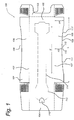
- Figure 1 is an illustration of a blank 100 used for assembling a bottom part 101 of a tray according to the present invention.
- the blank 100 has a bottom wall 102, a front wall 103, a back wall 104, a first side wall 105 and a second side wall 106.
- the blank 100 includes a number of fold lines 107 extending between the various walls of the bottom part 101 of the tray.
- the hatched areas indicated in Figure 1 are the areas that are glued in order to assemble the bottom part 101 of the tray.
- the first side wall 105 and the second side wall 106 have a length L.
- the length L is preferably ranging between 300 mm and 400 mm, as for example 354 mm.
- the first side wall 105 and the second side wall 106 have an upper edge 108 at a distance H1 from the fold line 107 between the bottom wall 102 and the first or second side wall 105, 106.
- the distance H1 corresponds with the height H1 of the upper edge of the first or second side wall 105, 106 above the bottom wall 102.
- the height H1 is preferably ranging between 40 mm and 60 mm, as for example 51 mm.
- both the first side wall 105 and the second side wall 106 are provided with a concave section 109.
- the concave section 109 has a minimum 110.
- This minimum 110 of the concave section 109 is situated at a distance H2 from the fold line 107 between the bottom wall 102 and the first or second side wall 105, 106.
- the height H2 is preferably ranging between 30 mm and 50 mm and is for example 40 mm.
- the concave section 109 preferably comprises at least one circle arc 111 having a radius R.
- the radius R is preferably greater than the length L of the tray, more preferably the radius R is at least 1.5 times the length L.
- the concave section 109 comprises two circle arcs 111, 111' having a radius R.
- the radius R is for example equal to 550 mm.
- Both circle arcs 111, 111' are connected by a straight line 112.
- Table 1 L (mm) H1 (mm) H2 (mm) H1/H2 R (mm) R/L Tray 1 352 51 40 0.78 550 1.56
- the bottom part 101 is provided with a tear strip 113.
- the tear strip 113 is formed by means of a perforated line 114.
- the tear strip 113 is preferably extending partially over the bottom wall 102 and partially over the back wall 104 so that when the tear strip 113 is removed an opening is created centrally in the bottom wall 102 and centrally in the back wall 104.
- the back wall 104 is further provided with an access opening 115 to facilitate the grasping and the removal of the tear strip 113.
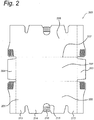
- FIG 2 is an illustration of a blank 200 used for assembling the cover part 201 of a tray according to the present invention.
- the blank 200 comprises a top wall 202, a front wall 203, a back wall 204, a first side wall 205 and a second side wall 206.
- the blank 200 includes a number of fold lines 207 extending between the various walls of the cover part 201 of the tray.
- the hatched areas indicated in Figure 2 are the areas that are glued in order to assemble the cover part 201 of the tray.
- the first and second side walls 205, 206 of the cover part 201 are provided with a first extension 213, a second extension 213' and a third extension 214.
- the first and second side walls 205, 206 are furthermore provided with an opening (access hole) 215 to facilitate the removal of the cover part 201 from the bottom part 101.
- the cover part 201 can be removably connected to the bottom part 101 by applying glue on section 216 of the first and the second side wall 205, 206.
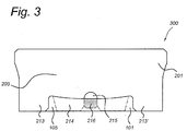
- FIG 3 shows the side view of a assembled tray 300 having a length 354 mm.
- the tray 300 comprises a bottom part 101 and a cover part 201.
- the bottom part 101 is obtained by assembling a blank 100 as shown in Figure 1 ;
- the cover part 201 is obtained by assembling a blank 200 as shown in Figure 2 .
- the cover part 201 is removably connected to the bottom part 101.
- the first extensions 213, 213' of the side wall 205 of the cover part 200 are extending downward from the cover part 200 to the bottom part 101 and are positioned at the outside side of the side wall 205.
- the third extension 214 of the side wall 205 is extending downward form the cover part 200 to the bottom part 100 and is positioned at the inside side of the side wall 205.
- the first extensions 213, 213' (and similarly the second extension 213') are visible whereas the third section 214 is not visible.
- the first and second side walls 205, 206 of the cover part are furthermore preferably provided with an opening (access hole) 215 to facilitate the removal of the cover part 201 from the bottom part 101.
- the cover part 201 is removably connected to the bottom part 101 by applying glue on section 216 of the first and the second side wall 205, 206.
- a preferred method to open tray 300 and to place tray 300 on a shelf, more particularly on a pushfeed system comprises the steps of :
- the first and/or second side wall 105, 106 of the bottom part are preferably bent laterally outwards by grasping the first and/or the second side wall 105, 106 of the bottom part 101 at the minimum of the concave section 109 of the first and/or the second side wall 105, 106 or alternatively at a location close to the minimum of the concave section 109 of the first and/or the second side wall 105, 106.
- the grasping of the first and/or second side wall 105, 106 can be facilitated by inserting at least one finger, for example the thumb in opening 215 thereby disconnecting the temporary connection means 216 between the bottom part 101 and the cover part 201.
Landscapes
- Engineering & Computer Science (AREA)
- Mechanical Engineering (AREA)
- Cartons (AREA)
Claims (15)
- Plateau pour maintenir et présenter des articles, ledit plateau comprenant une partie de fond (101), ladite partie de fond (101) et une partie de couvercle (201), la partie de couvercle est raccordée de manière amovible à la partie de fond, comprenant :une paroi de fond (102) ;une paroi avant (103) et une paroi arrière (104), à la fois ladite paroi avant (103) et ladite paroi arrière (104) s'étendant verticalement vers le haut à partir de ladite paroi de fond (102) et étant mutuellement opposées ;une première paroi latérale (105) et une seconde paroi latérale (106), à la fois ladite première paroi latérale (105) et ladite seconde paroi latérale (106) ayant une longueur L, ladite première paroi latérale (105) et ladite seconde paroi latérale (106) s'étendant verticalement vers le haut à partir de ladite paroi de fond (102) et étant mutuellement opposées ;moyennant quoi au moins l'une de ladite première paroi latérale (105) ou ladite seconde paroi latérale (106) a un bord supérieur droit orienté parallèlement à ladite paroi de fond (102) à une hauteur H1 au-dessus de ladite paroi de fond (102), ledit bord supérieur droit étant prévu avec une section concave (109), ladite section concave (109) ayant une forme symétrique et ayant son minimum à une hauteur H2 au-dessus de ladite paroi de fond (102), caractérisé par un rapport de la hauteur H2 sur la hauteur H1 (H2/H1) compris entre 0,6 et 0,9, etla courbe décrivant la section concave (109) comprend au moins un arc de cercle ayant un rayon R, moyennant quoi ledit rayon R est supérieur à 1,5 fois la longueur L de ladite première et de ladite seconde paroi latérale (105, 106).
- Plateau selon la revendication 1, moyennant quoi le bord supérieur à la fois de ladite première et de ladite seconde paroi latérale (105, 106) est prévu avec une section concave (109).
- Plateau selon l'une quelconque des revendications précédentes, moyennant quoi ladite section concave (109) s'étend sur une longueur d de ladite première ou ladite seconde paroi latérale (105, 106), ladite longueur d étant définie comme étant la longueur de la saillie de ladite section concave (109) dans le plan de ladite première ou de ladite seconde paroi latérale (105, 106) sur le plan de ladite paroi de fond (102), moyennant quoi ladite longueur d représente au moins 60 % de la longueur L de ladite première ou de ladite seconde paroi latérale (105, 106).
- Plateau selon l'une quelconque des revendications précédentes, moyennant quoi ladite partie de fond (101) est prévue avec une bande de déchirure (113) s'étendant au moins partiellement sur ladite paroi arrière (104) ou au moins partiellement sur ladite paroi arrière (104) et au moins partiellement sur ladite paroi de fond (102).
- Plateau selon l'une quelconque des revendications précédentes, moyennant quoi ledit plateau comprend en outre une partie de couvercle (201), ladite partie de couvercle (201) comprenant une paroi supérieure (202), une paroi avant (203), une paroi arrière (204), une première paroi latérale (205) et une seconde paroi latérale (206), moyennant quoi ladite paroi avant (203), ladite paroi arrière (204), ladite première paroi latérale (205) et ladite seconde paroi latérale (206) de ladite partie de couvercle (201) s'étendent verticalement vers le bas à partir de ladite paroi supérieure (202), ladite paroi avant (203) et ladite paroi arrière (204) étant mutuellement opposées et ladite première paroi latérale (205) et ladite seconde paroi latérale (206) étant mutuellement opposées.
- Plateau selon la revendication 5, moyennant quoi ladite partie de couvercle (201) et ladite partie de fond (101) sont raccordées au moyen d'un moyen de raccordement temporaire.
- Plateau selon la revendication 6, moyennant quoi ledit moyen de raccordement temporaire comprend de la colle ou un adhésif thermofusible.
- Plateau selon l'une quelconque des revendications 5 à 7, moyennant quoi au moins l'une parmi ladite première ou ladite seconde paroi latérale (205, 206) de ladite partie de couvercle (201) est prévue avec une première et une deuxième extension (213, 213'), ladite première et ladite deuxième extension (213, 213') étant situées dans le plan de ladite première ou ladite seconde paroi latérale (205, 206) et s'étendant vers le bas à partir de la paroi supérieure (202), ladite première et ladite deuxième extension (213, 213') étant positionnées au niveau du côté externe de ladite première et/ou seconde paroi latérale (105, 106) de la partie de fond (101) lorsque ladite partie de couvercle (201) est raccordée de manière amovible à ladite partie de fond (101).
- Plateau selon la revendication 8, moyennant quoi au moins l'une de ladite première ou de ladite seconde paroi latérale (205, 206) de ladite partie de couvercle (201) est prévue avec une troisième extension (214), ladite troisième extension (214) étant située dans le plan de ladite première ou de ladite seconde paroi latérale (205, 206) et s'étendant vers le bas à partir de la paroi supérieure (202), ladite troisième extension (214) étant positionnée entre ladite première et ladite deuxième extension (212, 213') et ladite troisième extension (214) étant positionnée au niveau du côté interne de la première et/ou seconde paroi latérale (205, 206) lorsque ladite partie de couvercle (201) est raccordée de manière amovible à ladite partie de fond (101).
- Plateau selon l'une quelconque des revendications précédentes, moyennant quoi au moins l'une de ladite première ou de ladite seconde paroi latérale (205, 206) de ladite partie de couvercle (201) ou au moins l'une de ladite première ou de ladite seconde paroi latérale (205, 206) de ladite partie de fond (101) est prévue avec une ouverture (215) pour faciliter le retrait de la partie de couvercle (201) de la partie de fond (101).
- Utilisation d'un plateau selon l'une quelconque des revendications 1 à 10 pour alimenter un système d'alimentation par poussée, caractérisée en ce que ledit système d'alimentation par poussée comprend au moins une plaque de poussoir pour pousser les articles présents dans ledit plateau vers l'avant, ladite plaque de poussoir étant entraînée par un moyen de sollicitation.
- Procédé pour ouvrir et placer un plateau selon l'une quelconque des revendications 1 à 10 comprenant une partie de fond (101) et une partie de couvercle (201) sur une étagère, ledit procédé étant caractérisé en ce qu'il comprend les étapes consistant à :desserrer ladite partie de couvercle (201) de ladite partie de fond (101) en pliant ladite première et/ou ladite seconde paroi latérale (105, 106) de ladite partie de fond (101) au moins partiellement latéralement vers l'extérieur ;retirer ladite partie de couvercle (201) de ladite partie de fond (101) en faisant coulisser ladite partie de couvercle (201) vers le haut.
- Procédé selon la revendication 12, moyennant quoi ladite première et/ou ladite seconde paroi latérale (105, 106) sont pliées latéralement vers l'extérieur en saisissant et en pliant ladite première et/ou ladite seconde paroi latérale (105, 106) au niveau dudit minimum de ladite section concave (109).
- Procédé selon la revendication 12 ou la revendication 13, moyennant quoi un moyen de raccordement temporaire est retiré avant ou pendant que ladite première et/ou ladite seconde paroi latérale (105, 106) sont pliées latéralement vers l'extérieur.
- Procédé pour ouvrir et placer un plateau sur un système d'alimentation par poussée, ledit plateau étant un plateau tel que défini selon l'une quelconque des revendications 1 à 10, caractérisé en ce qu'il comprend une partie de fond (101) et une partie de couvercle (201), moyennant quoi ladite partie de fond (101) est prévue avec une bande de déchirure (113), ledit procédé comprenant les étapes consistant à :retirer la bande de déchirure (113) de la paroi arrière (104) et/ou de la paroi de fond (102) de ladite partie de fond (101) dudit plateau ;desserrer ladite partie de couvercle (201) de ladite partie de fond (101) en pliant ladite première et/ou ladite seconde paroi latérale (105, 106) de ladite partie de fond (101) au moins partiellement latéralement vers l'extérieur ;retirer ladite partie de couvercle (201) de ladite partie de fond (101) en faisant coulisser ladite partie de couvercle (201) vers le haut ;placer ladite partie de fond (101) dudit plateau sur le système d'alimentation par poussée en poussant ladite partie de fond (101) contre la force d'alimentation par poussée dudit système d'alimentation par poussée.
Applications Claiming Priority (1)
| Application Number | Priority Date | Filing Date | Title |
|---|---|---|---|
| EP16154165 | 2016-02-04 |
Publications (2)
| Publication Number | Publication Date |
|---|---|
| EP3202680A1 EP3202680A1 (fr) | 2017-08-09 |
| EP3202680B1 true EP3202680B1 (fr) | 2018-12-26 |
Family
ID=55304899
Family Applications (1)
| Application Number | Title | Priority Date | Filing Date |
|---|---|---|---|
| EP17150101.8A Active EP3202680B1 (fr) | 2016-02-04 | 2017-01-03 | Plateau servant à maintenir et présenter des articles et procédé pour ouvrir et placer un tel plateau sur une étagère |
Country Status (1)
| Country | Link |
|---|---|
| EP (1) | EP3202680B1 (fr) |
Cited By (1)
| Publication number | Priority date | Publication date | Assignee | Title |
|---|---|---|---|---|
| US12195245B2 (en) | 2019-11-22 | 2025-01-14 | S.C. Johnson & Son, Inc. | Displayable shipping carton |
Families Citing this family (1)
| Publication number | Priority date | Publication date | Assignee | Title |
|---|---|---|---|---|
| CN108482789B (zh) * | 2018-03-15 | 2024-07-26 | 东莞市美盈森环保科技有限公司 | 一种包装结构及包装结构的制作工艺 |
Family Cites Families (7)
| Publication number | Priority date | Publication date | Assignee | Title |
|---|---|---|---|---|
| GB893562A (en) * | 1958-04-10 | 1962-04-11 | Philips Electrical Ind Ltd | Improvements in or relating to folding boxes adapted for stacking and nesting |
| DE7536839U (de) * | 1975-11-20 | 1976-03-18 | Osthushenrich Kg | Aufrichteschachtel |
| US4373659A (en) * | 1978-08-24 | 1983-02-15 | Champion International Corporation | Stackable carton with lid |
| US4826016A (en) * | 1988-04-22 | 1989-05-02 | The Gillette Co. | Subdividable carton for containerized products |
| US5195677A (en) * | 1992-05-15 | 1993-03-23 | Tone Brothers, Inc. | Hood and tray carton and blanks for forming same |
| FR2917382B1 (fr) * | 2007-06-15 | 2011-05-20 | Saica France | Emballage de type plateau pour le transport a plat et la presentation sur le lieu de vente du contenu apres redressement |
| DE202010007121U1 (de) * | 2010-05-21 | 2011-10-24 | Seda S.P.A. | Verpackungsbehälter und dafür geeigneter Rohling |
-
2017
- 2017-01-03 EP EP17150101.8A patent/EP3202680B1/fr active Active
Non-Patent Citations (1)
| Title |
|---|
| None * |
Cited By (1)
| Publication number | Priority date | Publication date | Assignee | Title |
|---|---|---|---|---|
| US12195245B2 (en) | 2019-11-22 | 2025-01-14 | S.C. Johnson & Son, Inc. | Displayable shipping carton |
Also Published As
| Publication number | Publication date |
|---|---|
| EP3202680A1 (fr) | 2017-08-09 |
Similar Documents
| Publication | Publication Date | Title |
|---|---|---|
| US8910856B2 (en) | Shipping and display container | |
| US7374047B2 (en) | Adjustable shipper display system | |
| CA2354959C (fr) | Boite-presentoir | |
| US7967154B1 (en) | System for supporting and displaying products in containers | |
| US20070074997A1 (en) | Combination shipping carton and twin dispenser boxes | |
| US20110121011A1 (en) | Product Dispensing System With Anti-Theft Engagement | |
| RU2549078C2 (ru) | Система выдачи продуктов | |
| US7959007B1 (en) | Shipping and display container with article support | |
| US4678088A (en) | Collapsible display and storage container | |
| US20130264923A1 (en) | Retail Display | |
| US3696940A (en) | Support structure | |
| WO2015110914A1 (fr) | Emballage | |
| US6978895B2 (en) | Tray with central offset score lines | |
| EP3202680A1 (fr) | Plateau servant à maintenir et présenter des articles et procédé pour ouvrir et placer un tel plateau sur une étagère | |
| US20040089579A1 (en) | Product packaging and display system and method having engaging means for structural display support | |
| US7784676B2 (en) | Carton having tear-away feature for shipping and handling multiple packages of products | |
| EP3030496B1 (fr) | Contenant rigide | |
| JP7069695B2 (ja) | 陳列収納箱 | |
| CN109890712B (zh) | 带后折翼的集成牵引系统 | |
| US10766659B2 (en) | Container, blank, modular display device, and method for forming a display device from the modular display device | |
| US6305598B1 (en) | Stackable package capable of division | |
| US20210078760A1 (en) | Display ready case and blank for forming the same | |
| US20130015093A1 (en) | Corrugated Paperboard Laminate Trays and Displays | |
| US20220127038A1 (en) | Modular packaging system | |
| EP2597046B1 (fr) | Boîte de présentation inclinable |
Legal Events
| Date | Code | Title | Description |
|---|---|---|---|
| PUAI | Public reference made under article 153(3) epc to a published international application that has entered the european phase |
Free format text: ORIGINAL CODE: 0009012 |
|
| STAA | Information on the status of an ep patent application or granted ep patent |
Free format text: STATUS: THE APPLICATION HAS BEEN PUBLISHED |
|
| AK | Designated contracting states |
Kind code of ref document: A1 Designated state(s): AL AT BE BG CH CY CZ DE DK EE ES FI FR GB GR HR HU IE IS IT LI LT LU LV MC MK MT NL NO PL PT RO RS SE SI SK SM TR |
|
| AX | Request for extension of the european patent |
Extension state: BA ME |
|
| STAA | Information on the status of an ep patent application or granted ep patent |
Free format text: STATUS: REQUEST FOR EXAMINATION WAS MADE |
|
| 17P | Request for examination filed |
Effective date: 20180109 |
|
| RBV | Designated contracting states (corrected) |
Designated state(s): AL AT BE BG CH CY CZ DE DK EE ES FI FR GB GR HR HU IE IS IT LI LT LU LV MC MK MT NL NO PL PT RO RS SE SI SK SM TR |
|
| RIC1 | Information provided on ipc code assigned before grant |
Ipc: B65D 5/20 20060101ALI20180614BHEP Ipc: B65D 5/54 20060101ALI20180614BHEP Ipc: B65D 5/68 20060101AFI20180614BHEP Ipc: B65D 5/32 20060101ALI20180614BHEP |
|
| GRAP | Despatch of communication of intention to grant a patent |
Free format text: ORIGINAL CODE: EPIDOSNIGR1 |
|
| STAA | Information on the status of an ep patent application or granted ep patent |
Free format text: STATUS: GRANT OF PATENT IS INTENDED |
|
| INTG | Intention to grant announced |
Effective date: 20180801 |
|
| GRAS | Grant fee paid |
Free format text: ORIGINAL CODE: EPIDOSNIGR3 |
|
| GRAA | (expected) grant |
Free format text: ORIGINAL CODE: 0009210 |
|
| STAA | Information on the status of an ep patent application or granted ep patent |
Free format text: STATUS: THE PATENT HAS BEEN GRANTED |
|
| AK | Designated contracting states |
Kind code of ref document: B1 Designated state(s): AL AT BE BG CH CY CZ DE DK EE ES FI FR GB GR HR HU IE IS IT LI LT LU LV MC MK MT NL NO PL PT RO RS SE SI SK SM TR |
|
| REG | Reference to a national code |
Ref country code: GB Ref legal event code: FG4D |
|
| REG | Reference to a national code |
Ref country code: CH Ref legal event code: EP |
|
| REG | Reference to a national code |
Ref country code: AT Ref legal event code: REF Ref document number: 1081081 Country of ref document: AT Kind code of ref document: T Effective date: 20190115 |
|
| REG | Reference to a national code |
Ref country code: IE Ref legal event code: FG4D |
|
| REG | Reference to a national code |
Ref country code: DE Ref legal event code: R096 Ref document number: 602017001481 Country of ref document: DE |
|
| REG | Reference to a national code |
Ref country code: NL Ref legal event code: FP |
|
| PG25 | Lapsed in a contracting state [announced via postgrant information from national office to epo] |
Ref country code: BG Free format text: LAPSE BECAUSE OF FAILURE TO SUBMIT A TRANSLATION OF THE DESCRIPTION OR TO PAY THE FEE WITHIN THE PRESCRIBED TIME-LIMIT Effective date: 20190326 Ref country code: FI Free format text: LAPSE BECAUSE OF FAILURE TO SUBMIT A TRANSLATION OF THE DESCRIPTION OR TO PAY THE FEE WITHIN THE PRESCRIBED TIME-LIMIT Effective date: 20181226 Ref country code: LT Free format text: LAPSE BECAUSE OF FAILURE TO SUBMIT A TRANSLATION OF THE DESCRIPTION OR TO PAY THE FEE WITHIN THE PRESCRIBED TIME-LIMIT Effective date: 20181226 Ref country code: NO Free format text: LAPSE BECAUSE OF FAILURE TO SUBMIT A TRANSLATION OF THE DESCRIPTION OR TO PAY THE FEE WITHIN THE PRESCRIBED TIME-LIMIT Effective date: 20190326 Ref country code: LV Free format text: LAPSE BECAUSE OF FAILURE TO SUBMIT A TRANSLATION OF THE DESCRIPTION OR TO PAY THE FEE WITHIN THE PRESCRIBED TIME-LIMIT Effective date: 20181226 Ref country code: HR Free format text: LAPSE BECAUSE OF FAILURE TO SUBMIT A TRANSLATION OF THE DESCRIPTION OR TO PAY THE FEE WITHIN THE PRESCRIBED TIME-LIMIT Effective date: 20181226 |
|
| REG | Reference to a national code |
Ref country code: LT Ref legal event code: MG4D |
|
| PG25 | Lapsed in a contracting state [announced via postgrant information from national office to epo] |
Ref country code: AL Free format text: LAPSE BECAUSE OF FAILURE TO SUBMIT A TRANSLATION OF THE DESCRIPTION OR TO PAY THE FEE WITHIN THE PRESCRIBED TIME-LIMIT Effective date: 20181226 Ref country code: RS Free format text: LAPSE BECAUSE OF FAILURE TO SUBMIT A TRANSLATION OF THE DESCRIPTION OR TO PAY THE FEE WITHIN THE PRESCRIBED TIME-LIMIT Effective date: 20181226 Ref country code: SE Free format text: LAPSE BECAUSE OF FAILURE TO SUBMIT A TRANSLATION OF THE DESCRIPTION OR TO PAY THE FEE WITHIN THE PRESCRIBED TIME-LIMIT Effective date: 20181226 Ref country code: GR Free format text: LAPSE BECAUSE OF FAILURE TO SUBMIT A TRANSLATION OF THE DESCRIPTION OR TO PAY THE FEE WITHIN THE PRESCRIBED TIME-LIMIT Effective date: 20190327 |
|
| REG | Reference to a national code |
Ref country code: AT Ref legal event code: MK05 Ref document number: 1081081 Country of ref document: AT Kind code of ref document: T Effective date: 20181226 |
|
| PG25 | Lapsed in a contracting state [announced via postgrant information from national office to epo] |
Ref country code: CZ Free format text: LAPSE BECAUSE OF FAILURE TO SUBMIT A TRANSLATION OF THE DESCRIPTION OR TO PAY THE FEE WITHIN THE PRESCRIBED TIME-LIMIT Effective date: 20181226 Ref country code: PL Free format text: LAPSE BECAUSE OF FAILURE TO SUBMIT A TRANSLATION OF THE DESCRIPTION OR TO PAY THE FEE WITHIN THE PRESCRIBED TIME-LIMIT Effective date: 20181226 Ref country code: ES Free format text: LAPSE BECAUSE OF FAILURE TO SUBMIT A TRANSLATION OF THE DESCRIPTION OR TO PAY THE FEE WITHIN THE PRESCRIBED TIME-LIMIT Effective date: 20181226 Ref country code: PT Free format text: LAPSE BECAUSE OF FAILURE TO SUBMIT A TRANSLATION OF THE DESCRIPTION OR TO PAY THE FEE WITHIN THE PRESCRIBED TIME-LIMIT Effective date: 20190426 |
|
| PG25 | Lapsed in a contracting state [announced via postgrant information from national office to epo] |
Ref country code: SM Free format text: LAPSE BECAUSE OF FAILURE TO SUBMIT A TRANSLATION OF THE DESCRIPTION OR TO PAY THE FEE WITHIN THE PRESCRIBED TIME-LIMIT Effective date: 20181226 Ref country code: EE Free format text: LAPSE BECAUSE OF FAILURE TO SUBMIT A TRANSLATION OF THE DESCRIPTION OR TO PAY THE FEE WITHIN THE PRESCRIBED TIME-LIMIT Effective date: 20181226 Ref country code: SK Free format text: LAPSE BECAUSE OF FAILURE TO SUBMIT A TRANSLATION OF THE DESCRIPTION OR TO PAY THE FEE WITHIN THE PRESCRIBED TIME-LIMIT Effective date: 20181226 Ref country code: IS Free format text: LAPSE BECAUSE OF FAILURE TO SUBMIT A TRANSLATION OF THE DESCRIPTION OR TO PAY THE FEE WITHIN THE PRESCRIBED TIME-LIMIT Effective date: 20190426 Ref country code: RO Free format text: LAPSE BECAUSE OF FAILURE TO SUBMIT A TRANSLATION OF THE DESCRIPTION OR TO PAY THE FEE WITHIN THE PRESCRIBED TIME-LIMIT Effective date: 20181226 |
|
| REG | Reference to a national code |
Ref country code: DE Ref legal event code: R097 Ref document number: 602017001481 Country of ref document: DE |
|
| PG25 | Lapsed in a contracting state [announced via postgrant information from national office to epo] |
Ref country code: LU Free format text: LAPSE BECAUSE OF NON-PAYMENT OF DUE FEES Effective date: 20190103 |
|
| REG | Reference to a national code |
Ref country code: BE Ref legal event code: MM Effective date: 20190131 |
|
| REG | Reference to a national code |
Ref country code: IE Ref legal event code: MM4A |
|
| PG25 | Lapsed in a contracting state [announced via postgrant information from national office to epo] |
Ref country code: AT Free format text: LAPSE BECAUSE OF FAILURE TO SUBMIT A TRANSLATION OF THE DESCRIPTION OR TO PAY THE FEE WITHIN THE PRESCRIBED TIME-LIMIT Effective date: 20181226 Ref country code: DK Free format text: LAPSE BECAUSE OF FAILURE TO SUBMIT A TRANSLATION OF THE DESCRIPTION OR TO PAY THE FEE WITHIN THE PRESCRIBED TIME-LIMIT Effective date: 20181226 Ref country code: MC Free format text: LAPSE BECAUSE OF FAILURE TO SUBMIT A TRANSLATION OF THE DESCRIPTION OR TO PAY THE FEE WITHIN THE PRESCRIBED TIME-LIMIT Effective date: 20181226 |
|
| PLBE | No opposition filed within time limit |
Free format text: ORIGINAL CODE: 0009261 |
|
| STAA | Information on the status of an ep patent application or granted ep patent |
Free format text: STATUS: NO OPPOSITION FILED WITHIN TIME LIMIT |
|
| PG25 | Lapsed in a contracting state [announced via postgrant information from national office to epo] |
Ref country code: BE Free format text: LAPSE BECAUSE OF NON-PAYMENT OF DUE FEES Effective date: 20190131 |
|
| 26N | No opposition filed |
Effective date: 20190927 |
|
| PG25 | Lapsed in a contracting state [announced via postgrant information from national office to epo] |
Ref country code: IE Free format text: LAPSE BECAUSE OF NON-PAYMENT OF DUE FEES Effective date: 20190103 |
|
| PG25 | Lapsed in a contracting state [announced via postgrant information from national office to epo] |
Ref country code: SI Free format text: LAPSE BECAUSE OF FAILURE TO SUBMIT A TRANSLATION OF THE DESCRIPTION OR TO PAY THE FEE WITHIN THE PRESCRIBED TIME-LIMIT Effective date: 20181226 |
|
| PG25 | Lapsed in a contracting state [announced via postgrant information from national office to epo] |
Ref country code: TR Free format text: LAPSE BECAUSE OF FAILURE TO SUBMIT A TRANSLATION OF THE DESCRIPTION OR TO PAY THE FEE WITHIN THE PRESCRIBED TIME-LIMIT Effective date: 20181226 |
|
| PG25 | Lapsed in a contracting state [announced via postgrant information from national office to epo] |
Ref country code: MT Free format text: LAPSE BECAUSE OF NON-PAYMENT OF DUE FEES Effective date: 20190103 |
|
| REG | Reference to a national code |
Ref country code: DE Ref legal event code: R081 Ref document number: 602017001481 Country of ref document: DE Owner name: UNILEVER IP HOLDINGS B.V., NL Free format text: FORMER OWNER: UNILEVER N.V., ROTTERDAM, NL |
|
| PG25 | Lapsed in a contracting state [announced via postgrant information from national office to epo] |
Ref country code: CY Free format text: LAPSE BECAUSE OF FAILURE TO SUBMIT A TRANSLATION OF THE DESCRIPTION OR TO PAY THE FEE WITHIN THE PRESCRIBED TIME-LIMIT Effective date: 20181226 |
|
| REG | Reference to a national code |
Ref country code: NL Ref legal event code: PD Owner name: UNILEVER IP HOLDINGS B.V.; NL Free format text: DETAILS ASSIGNMENT: CHANGE OF OWNER(S), ASSIGNMENT; FORMER OWNER NAME: UNILEVER N.V. Effective date: 20210413 |
|
| PG25 | Lapsed in a contracting state [announced via postgrant information from national office to epo] |
Ref country code: HU Free format text: LAPSE BECAUSE OF FAILURE TO SUBMIT A TRANSLATION OF THE DESCRIPTION OR TO PAY THE FEE WITHIN THE PRESCRIBED TIME-LIMIT; INVALID AB INITIO Effective date: 20170103 |
|
| REG | Reference to a national code |
Ref country code: GB Ref legal event code: 732E Free format text: REGISTERED BETWEEN 20211125 AND 20211201 |
|
| PG25 | Lapsed in a contracting state [announced via postgrant information from national office to epo] |
Ref country code: MK Free format text: LAPSE BECAUSE OF FAILURE TO SUBMIT A TRANSLATION OF THE DESCRIPTION OR TO PAY THE FEE WITHIN THE PRESCRIBED TIME-LIMIT Effective date: 20181226 |
|
| P01 | Opt-out of the competence of the unified patent court (upc) registered |
Effective date: 20230501 |
|
| REG | Reference to a national code |
Ref country code: CH Ref legal event code: U11 Free format text: ST27 STATUS EVENT CODE: U-0-0-U10-U11 (AS PROVIDED BY THE NATIONAL OFFICE) Effective date: 20260201 |
|
| PGFP | Annual fee paid to national office [announced via postgrant information from national office to epo] |
Ref country code: NL Payment date: 20260121 Year of fee payment: 10 |
|
| PGFP | Annual fee paid to national office [announced via postgrant information from national office to epo] |
Ref country code: GB Payment date: 20260123 Year of fee payment: 10 |
|
| PGFP | Annual fee paid to national office [announced via postgrant information from national office to epo] |
Ref country code: DE Payment date: 20260121 Year of fee payment: 10 |
|
| PGFP | Annual fee paid to national office [announced via postgrant information from national office to epo] |
Ref country code: IT Payment date: 20260123 Year of fee payment: 10 |
|
| PGFP | Annual fee paid to national office [announced via postgrant information from national office to epo] |
Ref country code: FR Payment date: 20260123 Year of fee payment: 10 |
|
| PGFP | Annual fee paid to national office [announced via postgrant information from national office to epo] |
Ref country code: CH Payment date: 20260201 Year of fee payment: 10 |