EP3202704B1 - Verfahren zur erkennung des defekten zustands eines produkts, das mit einem giessbaren produkt kontaktbefüllt werden soll, und füllvorrichtung - Google Patents
Verfahren zur erkennung des defekten zustands eines produkts, das mit einem giessbaren produkt kontaktbefüllt werden soll, und füllvorrichtung Download PDFInfo
- Publication number
- EP3202704B1 EP3202704B1 EP16305145.1A EP16305145A EP3202704B1 EP 3202704 B1 EP3202704 B1 EP 3202704B1 EP 16305145 A EP16305145 A EP 16305145A EP 3202704 B1 EP3202704 B1 EP 3202704B1
- Authority
- EP
- European Patent Office
- Prior art keywords
- filling
- article
- fluidic line
- station
- pourable product
- Prior art date
- Legal status (The legal status is an assumption and is not a legal conclusion. Google has not performed a legal analysis and makes no representation as to the accuracy of the status listed.)
- Not-in-force
Links
Images



Classifications
-
- B—PERFORMING OPERATIONS; TRANSPORTING
- B67—OPENING, CLOSING OR CLEANING BOTTLES, JARS OR SIMILAR CONTAINERS; LIQUID HANDLING
- B67C—CLEANING, FILLING WITH LIQUIDS OR SEMILIQUIDS, OR EMPTYING, OF BOTTLES, JARS, CANS, CASKS, BARRELS, OR SIMILAR CONTAINERS, NOT OTHERWISE PROVIDED FOR; FUNNELS
- B67C3/00—Bottling liquids or semiliquids; Filling jars or cans with liquids or semiliquids using bottling or like apparatus; Filling casks or barrels with liquids or semiliquids
- B67C3/007—Applications of control, warning or safety devices in filling machinery
-
- B—PERFORMING OPERATIONS; TRANSPORTING
- B65—CONVEYING; PACKING; STORING; HANDLING THIN OR FILAMENTARY MATERIAL
- B65C—LABELLING OR TAGGING MACHINES, APPARATUS, OR PROCESSES
- B65C3/00—Labelling other than flat surfaces
- B65C3/26—Affixing labels to non-rigid containers, e.g. bottles made of polyethylene or boxes to be inflated by internal air pressure prior to labelling
-
- B—PERFORMING OPERATIONS; TRANSPORTING
- B67—OPENING, CLOSING OR CLEANING BOTTLES, JARS OR SIMILAR CONTAINERS; LIQUID HANDLING
- B67C—CLEANING, FILLING WITH LIQUIDS OR SEMILIQUIDS, OR EMPTYING, OF BOTTLES, JARS, CANS, CASKS, BARRELS, OR SIMILAR CONTAINERS, NOT OTHERWISE PROVIDED FOR; FUNNELS
- B67C3/00—Bottling liquids or semiliquids; Filling jars or cans with liquids or semiliquids using bottling or like apparatus; Filling casks or barrels with liquids or semiliquids
- B67C3/02—Bottling liquids or semiliquids; Filling jars or cans with liquids or semiliquids using bottling or like apparatus
- B67C3/06—Bottling liquids or semiliquids; Filling jars or cans with liquids or semiliquids using bottling or like apparatus using counterpressure, i.e. filling while the container is under pressure
- B67C3/10—Bottling liquids or semiliquids; Filling jars or cans with liquids or semiliquids using bottling or like apparatus using counterpressure, i.e. filling while the container is under pressure preliminary filling with inert gases, e.g. carbon dioxide
-
- B—PERFORMING OPERATIONS; TRANSPORTING
- B67—OPENING, CLOSING OR CLEANING BOTTLES, JARS OR SIMILAR CONTAINERS; LIQUID HANDLING
- B67C—CLEANING, FILLING WITH LIQUIDS OR SEMILIQUIDS, OR EMPTYING, OF BOTTLES, JARS, CANS, CASKS, BARRELS, OR SIMILAR CONTAINERS, NOT OTHERWISE PROVIDED FOR; FUNNELS
- B67C3/00—Bottling liquids or semiliquids; Filling jars or cans with liquids or semiliquids using bottling or like apparatus; Filling casks or barrels with liquids or semiliquids
- B67C3/02—Bottling liquids or semiliquids; Filling jars or cans with liquids or semiliquids using bottling or like apparatus
- B67C3/20—Bottling liquids or semiliquids; Filling jars or cans with liquids or semiliquids using bottling or like apparatus with provision for metering the liquids to be introduced, e.g. when adding syrups
-
- B—PERFORMING OPERATIONS; TRANSPORTING
- B67—OPENING, CLOSING OR CLEANING BOTTLES, JARS OR SIMILAR CONTAINERS; LIQUID HANDLING
- B67C—CLEANING, FILLING WITH LIQUIDS OR SEMILIQUIDS, OR EMPTYING, OF BOTTLES, JARS, CANS, CASKS, BARRELS, OR SIMILAR CONTAINERS, NOT OTHERWISE PROVIDED FOR; FUNNELS
- B67C3/00—Bottling liquids or semiliquids; Filling jars or cans with liquids or semiliquids using bottling or like apparatus; Filling casks or barrels with liquids or semiliquids
- B67C3/02—Bottling liquids or semiliquids; Filling jars or cans with liquids or semiliquids using bottling or like apparatus
- B67C3/22—Details
- B67C3/24—Devices for supporting or handling bottles
-
- B—PERFORMING OPERATIONS; TRANSPORTING
- B67—OPENING, CLOSING OR CLEANING BOTTLES, JARS OR SIMILAR CONTAINERS; LIQUID HANDLING
- B67C—CLEANING, FILLING WITH LIQUIDS OR SEMILIQUIDS, OR EMPTYING, OF BOTTLES, JARS, CANS, CASKS, BARRELS, OR SIMILAR CONTAINERS, NOT OTHERWISE PROVIDED FOR; FUNNELS
- B67C3/00—Bottling liquids or semiliquids; Filling jars or cans with liquids or semiliquids using bottling or like apparatus; Filling casks or barrels with liquids or semiliquids
- B67C3/02—Bottling liquids or semiliquids; Filling jars or cans with liquids or semiliquids using bottling or like apparatus
- B67C3/22—Details
- B67C3/28—Flow-control devices, e.g. using valves
- B67C3/286—Flow-control devices, e.g. using valves related to flow rate control, i.e. controlling slow and fast filling phases
Definitions
- the present invention relates to a method for detecting the defective status of an article to be contact filled with a pourable product.
- the present invention also relates to a filling device for contact filling an article with a pourable product.
- pourable food product comprising not only food product like milk, fruit juice or beverages in general, but also detergents are sold in articles having different shapes and dimensions.
- These articles are typically made within bottling units, which comprise a plurality of stations for carrying out respective operations on the articles.
- the bottling unit comprises, in the following sequence, at least one blowing station for blowing a plurality of pre-forms and forming relative articles, one filling unit for filling the articles with a pourable food product, one capping station for applying a plurality of caps onto the respective articles and one labelling station for applying labels onto the outer surface of respective articles.
- the labelling station is arranged downstream of the filling station and the bottling unit further comprises a plurality of rectilinear/curvilinear transfer elements, e.g. rectilinear guides and/or star-wheels, for transferring the articles from the filling station to the labelling station.
- rectilinear/curvilinear transfer elements e.g. rectilinear guides and/or star-wheels
- the filling station, the capping station and the labelling station are enclosed in only one machine.
- Such a filling device according to the preamble of claim 9 and a corresponding filling method is known from EP 1 661 848 A1 .
- the aforementioned object is achieved by the present invention as it relates to a method for detecting the defective status of an article intended to be contact filled with a pourable product, as claimed in claim 1.
- the present invention also relates to a filling device for contact filling an article with a pourable product, as claimed in claim 9.
- numeral 1 indicates as a whole a unit for manufacturing articles 2 with a pourable product.
- Unit 1 comprises, in sequence and in this sequence, ( Figure 1 ):
- unit 1 comprises a transfer station 6 for transferring articles 2 along a curved transfer path and from capping station 5 to labelling station 7.
- filling station 4, capping station 5, labelling station 7 are defined by only one machine 18.
- Each article 2 comprises ( Figures 1 to 5 ), in a known manner,:
- Filling station 4 comprises, in turn,:
- filling device 17 is adapted to contact filling a relative article 2, with a pourable product, which can be selectively either carbonated or still, i.e. not carbonated.
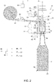
- Filling device 17 substantially comprises:
- Support 20 is carried by the outer periphery of carousel in a position below body 10.
- Axis A of filling device 17 is spaced from and parallel to the axis of rotation of carousel.
- Support 20 receives a relative empty article 2 at an inlet station (not-shown), convey relative article 2 along an arc-shaped trajectory, and output filled article 2 at an outlet station (not-shown).
- Support 20 is movable parallel to axis A between:
- support 20 is arranged in the relative rest position at inlet station and at the outlet station, and moves from the rest position to the lowered position and vice-versa along the arc-shaped trajectory.
- article 2 preferably undergoes the following operations according the so-called contact filling modality:
- Body 10 further comprises:
- fluidic line 19 comprises:
- valves 22, 23 are arranged along relative ducts 28, 29.
- valves 22, 23 can be selectively set in:
- valves (not only valves 22, 23) are depicted in white when set in respective closed positions and are depicted in black when set in respective open positions.
- valves 22, 23 are set in the respective open positions, during the pressurization step of article 2, while they are set in the respective closed positions when the vacuum-generation step and during the de-pressurization step.
- Body 10 further comprises:
- valve 42 is set in the open position, during the de-pressurization step of article 2, while is set in the closed position while the other operations are carried out on article 2.
- body 10 comprises
- Section 43 is, in particular, interposed between valve 42 and opening 14 along fluidic line 40.
- fluidic line 50 is formed as a derivation of fluidic line 40.
- Section 43 is fluidly connected with opening 14 also when shutter 15 is in the closed position.
- fluidic line 40 opens into opening 14 below the position reached by shutter 15 in the closed position.
- valve 52 is set in the open position during the vacuum generation step of article 2, and is set in the closed position during the other operations on article 2.
- Filling device 17 preferably comprises a flow-meter 80, which is arranged along a duct 81 extending between tank 13 and opening 12, and is adapted to measure the flow Q - and, therefore, the quantity - of pourable product filled inside article 2, when shutter 15 is in the open position.
- Filling station 4 comprises a control unit 60 (only schematically shown in Figures 1 to 5 ), which is programmed for controlling shutters 15, valves 22, 23 and valves 42, 52 and supports 20 of all filling devices 17.
- control unit 60 is advantageously programmed for ( Figure 3 ), when supports 20 are in the respective raised position,:
- valves 22, 23 are in the respective closed position, the air contained in article 2 is prevented from flowing along duct 24 and, therefore, from escaping from article 2. Accordingly, the pourable product is prevented from entering article 2 and, therefore, flow Q should theoretically equal to zero. However, flow Q is slightly more than zero due to the elasticity of the air contained inside article 2, which allows a small amount of pourable product to enter article 2.
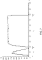
- control unit 60 is programmed for carrying out steps i) and ii) during an interval time t1 ( Figure 2 ) and an interval time t2 consequent to one another, and for carrying out step iii) only during interval time t2 ( Figure 3 ).
- the flow Q can adjust before its value is used for detecting the defective status of article 2.
- a small flow Q can enter article 2, due to the elasticity of the air contained therein.
- the length of first time interval t1 and/or the threshold value can be adjusted by an operator on the basis of the format of article 2 and of the desired filling level of article 2.
- control unit 60 is programmed for:
- steps iv) and v) are carried out after step iii) and time interval t3 is subsequent to time intervals t1 and t2.
- a software product can be loaded onto control unit 60 which, when executed, implements previously identified steps i)-v).
- Filling station 4 further defines a single flow-meter 80 and duct 81, and single collectors 41, 51 for all filling devices 17.
- the operation of the filling station 4 will be described with reference to the filling of articles 2 with a still pourable product and with reference to only one filling device 17 and article 2.
- filling device 17 will be described as of the condition shown in Figure 1 , in which shutter 15, valves 22, 23, 42, 52 are in the respective closed positions.
- support 20 is in the rest position and mouth 8 of empty article 2 is spaced along axis A from opening 14 and body 10.
- control unit 60 sets shutter 15 in the open position and keeps valves 22, 23, 42, 52 in respective closed positions for time intervals t1 ( Figure 2 ) and t2 ( Figure 3 ).
- mouth 8 is in tight-fluid contact with body 10 of filling device 17.
- valves 22, 23 are in the respective closed positions, the air contained in article 2 is prevented from escaping from article 2 along ducts 24, 25.
- flow Q of pourable product should theoretically equal zero, due to the fact the pourable product is prevented from entering inside article 2.
- control unit 60 does not compare flow Q detected by flow-meter 80 with threshold value. Accordingly, the flow Q can reach a regime value slightly greater than zero.
- the length of time interval t1 can be selectively adjusted on the basis of at least the format and/or the desired filling level of article 2.
- control unit 60 compares flow Q detected by flow-meter 80 with threshold value, in order to detect whether or not article 2 is defective, i.e. is holed.
- control unit 60 subsequently:
- control unit 60 sets shutter 15 and valve 22 in the closed position and displaces support 20 in the lowered position.
- article 2 filled with flat pourable product is discharged from support 20 and transferred from filling station 4 to transfer station 6.
- Filling device 17 is particularly flexible, because it can be employed, without any substantial re-designing, for contact filling both carbonated and still pourable products.
- filling valve 17 could not comprise collector 21 and the pressurized gas could be stored in tank 13.
- valve 22, 23 could be provided.
Landscapes
- Physics & Mathematics (AREA)
- Fluid Mechanics (AREA)
- Chemical & Material Sciences (AREA)
- Chemical Kinetics & Catalysis (AREA)
- Basic Packing Technique (AREA)
- Filling Of Jars Or Cans And Processes For Cleaning And Sealing Jars (AREA)
Claims (15)
- Verfahren zum Detektieren des fehlerhaften Zustands eines Artikels (2), der dazu gedacht ist, mit einem gießbaren Produkt, das in einem Tank (13) gelagert ist, mit Hilfe einer Füllvorrichtung (17) kontaktgefüllt zu werden;
wobei die Füllvorrichtung (17) Folgendes umfasst:- eine erste Fluidleitung (11), die in einer selektiven Weise mit dem Tank (13) fluidtechnisch verbindbar ist, die mit einer Füllöffnung (14) der Füllvorrichtung (17) verbunden ist und die ausgelegt ist, einen Strom des gießbaren Produktes von dem Tank (13) in Richtung der Füllöffnung (14) zu befördern;- ein erstes Ventil (15), das entlang der ersten Fluidleitung (11) eingefügt ist und das wahlweise entweder in einer ersten offenen Position, in der es das Fließen des gießbaren Produktes entlang der ersten Fluidleitung (11) und in Richtung der Füllöffnung (14) erlaubt, oder in einer ersten geschlossenen Position, in der es verhindert, dass das gießbare Produkt entlang der ersten Fluidleitung (11) fließt, angeordnet werden kann;- eine zweite Fluidleitung (24, 25), die mit der Füllöffnung (14) fluidtechnisch verbunden ist und ausgelegt ist, das Entweichen eines gasförmigen Anteils, der in dem Artikel (2) enthalten ist, während seines Füllens zu erlauben; und- mindestens ein zweites Ventil (22, 23), das entlang der zweiten Fluidleitung (24, 25) eingefügt ist und wahlweise entweder in einer zweiten offenen Position, in der es das Fließen des gasförmigen Anteils entlang der zweiten Fluidleitung (24, 25) und weg von der Füllöffnung (14) erlaubt, oder in einer zweiten geschlossenen Position, in der es verhindert, dass der gasförmige Anteil entlang der zweiten Fluidleitung (24, 25) fließt, angeordnet werden kann;wobei das Verfahren die folgenden Schritte umfasst:i) Erzeugen eines fluiddichten Kontakts zwischen einer Öffnung (8) des Artikels (2) und der ersten Fluidleitung (11);ii) Einstellen des zweiten Ventils (22, 23) in die zweite geschlossene Position;iii) Einstellen des ersten Ventils (15) in die erste offene Position während des Schritts (ii);iv) Messen des Stroms (Q) des gießbaren Produktes entlang der ersten Fluidleitung (11) während der Schritte ii) und iii); undv) Detektieren, dass der Artikel (2) fehlerhaft ist, falls der Strom (Q) größer als ein Schwellenwert ist. - Verfahren nach Anspruch 1, dadurch gekennzeichnet, dass es umfasst, dass die Schritte ii) und iii) sowohl während eines ersten Zeitintervalls (t1) als auch eines zweiten Zeitintervalls (t2), die aufeinanderfolgend sind, ausgeführt werden, und dadurch, dass der Schritt v) nur während des zweiten Zeitintervalls (t2) ausgeführt wird.
- Verfahren nach Anspruch 2, dadurch gekennzeichnet, dass es den Schritt vi) des Einstellens des mindestens einen zweiten Ventils (22, 23) in die zweite offene Position nach dem zweiten Zeitintervall (t2) umfasst.
- Verfahren nach einem der vorhergehenden Ansprüche, dadurch gekennzeichnet, dass der Schwellenwert selektiv einstellbar ist.
- Verfahren nach einem der Ansprüche 2 bis 4, dadurch gekennzeichnet, dass das erste Zeitintervall (t1) selektiv einstellbar ist.
- Verfahren nach einem der vorhergehenden Ansprüche, dadurch gekennzeichnet, dass das gießbare Produkt nicht mit Kohlensäure versetzt ist.
- Verfahren nach einem der vorhergehenden Ansprüche, dadurch gekennzeichnet, dass es die folgenden Schritte umfasst:vii) Anbringen eines Etiketts auf dem gefüllten Artikel (2) innerhalb einer Etikettierstation (7) und nach dem Abschluss des Füllens des Artikels (2); undviii) Übertragen des gefüllten Artikels (2) an eine Etikettierstation (7) entlang eines gekrümmten Wegs.
- Softwareprodukt, das in eine Steuereinheit (60) einer Füllvorrichtung (17) zum Füllen eines Artikels (2) mit einem gießbaren Produkt geladen werden kann und das dann, wenn es ausgeführt wird, die Schritte des Verfahrens nach einem der vorhergehenden Ansprüche ausführt.
- Füllvorrichtung (17) zum Kontaktfüllen eines Artikels (2) mit einem gießbaren Produkt, die Folgendes umfasst:- eine Füllöffnung (14);- eine erste Fluidleitung (11), die in einer selektiven Weise mit einem Tank (13) fluidtechnisch verbindbar ist, die mit der Füllöffnung (14) verbunden ist und ausgelegt ist, einen Strom des gießbaren Produktes von dem Tank (13) in Richtung der Füllöffnung (14) zu befördern;- ein erstes Ventil (15), das entlang der ersten Fluidleitung (11) eingefügt ist und das wahlweise entweder in einer ersten offenen Position, in der es das Fließen des gießbaren Produktes entlang der ersten Fluidleitung (11) und in Richtung der Füllöffnung (14) erlaubt, oder in einer ersten geschlossenen Position, in der es verhindert, dass das gießbare Produkt entlang der ersten Fluidleitung (11) fließt, angeordnet werden kann;- eine zweite Fluidleitung (24, 25), die mit der Füllöffnung (14) fluidtechnisch verbunden ist und ausgelegt ist, das Entweichen eines gasförmigen Anteils, der in dem Artikel (2) enthalten ist, während seines Füllens zu erlauben; und- mindestens ein zweites Ventil (22, 23), das entlang der zweiten Fluidleitung (24, 25) eingefügt ist und wahlweise entweder in einer zweiten offenen Position, in der es das Fließen des gasförmigen Anteils entlang der zweiten Fluidleitung (24, 25) und weg von der Füllöffnung (14) erlaubt, oder in einer zweiten geschlossenen Position, in der es verhindert, dass der gasförmige Anteil entlang der zweiten Fluidleitung (24, 25) fließt, angeordnet werden kann; und- eine Messvorrichtung (80), die ausgelegt ist, eine Größe zu messen, die einem Strom (Q) des gießbaren Produktes entlang der ersten Fluidleitung (24, 25) zugeordnet ist;wobei die Füllöffnung (14) ausgelegt ist, in einem fluiddichten Kontakt mit einer Öffnung (8) des Artikels (2) während seines Kontaktfüllens zu sein;
dadurch gekennzeichnet, dass sie eine Steuereinheit (60) umfasst, die programmiert ist zum:i) Einstellen des zweiten Ventils (22, 23) in der zweiten geschlossenen Position;ii) Einstellen des ersten Ventils (15) in der ersten offenen Position während des Schritts ii); undiii) Detektieren, dass der Artikel (2) fehlerhaft ist, falls der Strom (Q) größer als ein Schwellenwert ist. - Füllvorrichtung nach Anspruch 9, dadurch gekennzeichnet, dass die Steuereinheit (60) programmiert ist zum:- Halten des zweiten Ventils (22, 23) in der zweiten geschlossenen Position und des ersten Ventils (15) in der ersten offenen Position für ein erstes Zeitintervall (t1) und ein zweites Zeitintervall (t2), die aufeinanderfolgend sind; und- Detektieren, ob der fehlerhafte Zustand des Artikels (2) nur während des zweiten Zeitintervalls (t2) fehlerhaft ist.
- Füllvorrichtung nach Anspruch 10, dadurch gekennzeichnet, dass die Steuereinheit (60) zum Einstellen des zweiten Ventils (22, 23) in die zweite offene Position nach dem zweiten Zeitintervall (t2) programmiert ist.
- Füllvorrichtung nach Anspruch 10 oder 11, dadurch gekennzeichnet, dass der Schwellenwert einstellbar ist.
- Füllvorrichtung nach einem der Ansprüche 9 bis 12, dadurch gekennzeichnet, dass das gießbare Produkt nicht mit Kohlensäure versetzt ist.
- Füllvorrichtung nach einem der Ansprüche 9 bis 13, dadurch gekennzeichnet, dass das erste Zeitintervall (t1) selektiv einstellbar ist.
- Einheit (1) zum Herstellen von Artikeln (2), die mit einem gießbaren Produkt gefüllt sind, die Folgendes umfasst:- eine Füllstation (4), die ausgelegt ist, die Artikel (2) mit dem Produkt zu füllen;- eine Etikettierstation (7), die ausgelegt ist, mehrere Etiketten auf den Artikeln (2) aufzubringen, und der Füllstation (4) in der Vorrückrichtung des Artikels (2) fortschreitend nachgelagert angeordnet ist; und- eine Umladestation (6), die zwischen die Füllstation (4) und die Etikettierstation (7) eingefügt ist und ausgelegt ist, die Artikel (2) entlang eines Wegs von der Füllstation (4) zu der Etikettierstation (7) umzuladen;wobei die Füllstation (4), die Etikettierstation (7) und die Umladestation (6) in einer einzigen Maschine (18) untergebracht sind;
dadurch gekennzeichnet, dass die Füllstation (4) mehrere Füllvorrichtungen (17) nach einem der Ansprüche 9 bis 14 umfasst.
Priority Applications (2)
| Application Number | Priority Date | Filing Date | Title |
|---|---|---|---|
| EP16305145.1A EP3202704B1 (de) | 2016-02-08 | 2016-02-08 | Verfahren zur erkennung des defekten zustands eines produkts, das mit einem giessbaren produkt kontaktbefüllt werden soll, und füllvorrichtung |
| US15/408,356 US10501301B2 (en) | 2016-02-08 | 2017-01-17 | Method for detecting the defective status of an article to be contact filled with a pourable product and filling device |
Applications Claiming Priority (1)
| Application Number | Priority Date | Filing Date | Title |
|---|---|---|---|
| EP16305145.1A EP3202704B1 (de) | 2016-02-08 | 2016-02-08 | Verfahren zur erkennung des defekten zustands eines produkts, das mit einem giessbaren produkt kontaktbefüllt werden soll, und füllvorrichtung |
Publications (2)
| Publication Number | Publication Date |
|---|---|
| EP3202704A1 EP3202704A1 (de) | 2017-08-09 |
| EP3202704B1 true EP3202704B1 (de) | 2018-09-26 |
Family
ID=55405288
Family Applications (1)
| Application Number | Title | Priority Date | Filing Date |
|---|---|---|---|
| EP16305145.1A Not-in-force EP3202704B1 (de) | 2016-02-08 | 2016-02-08 | Verfahren zur erkennung des defekten zustands eines produkts, das mit einem giessbaren produkt kontaktbefüllt werden soll, und füllvorrichtung |
Country Status (2)
| Country | Link |
|---|---|
| US (1) | US10501301B2 (de) |
| EP (1) | EP3202704B1 (de) |
Citations (15)
| Publication number | Priority date | Publication date | Assignee | Title |
|---|---|---|---|---|
| US2606657A (en) | 1948-02-06 | 1952-08-12 | Pneumatic Scale Corp | Bottle testing and sorting apparatus |
| DE4239238A1 (de) | 1992-11-21 | 1994-05-26 | Khs Masch & Anlagenbau Ag | Verfahren sowie Vorrichtung zum Füllen von Flaschen oder dergleichen Behälter aus Kunststoff (insbesondere PET-Flaschen) mit einem flüssigen Füllgut |
| DE19703528A1 (de) | 1996-11-25 | 1998-08-06 | Kronseder Maschf Krones | Verfahren und Vorrichtung zur Dichtigkeitsprüfung von verschlossenen Flaschen o. dgl. |
| FR2777877A1 (fr) | 1998-04-27 | 1999-10-29 | A L G I | Procede et dispositif de remplissage d'un recipient a verification de fuite |
| US20020139434A1 (en) | 2001-03-31 | 2002-10-03 | Dave Meheen | Filling apparatus and methods |
| EP1661848A1 (de) | 2004-11-30 | 2006-05-31 | Shibuya Kogyo Co., Ltd | Füllorgan mit ersetzbaren Ausläufen |
| EP1897848A1 (de) | 2006-09-11 | 2008-03-12 | Suntory Limited | Vorrichtung zur Beurteilung von Füllfehlern und Füllvorrichtung |
| WO2010131271A1 (en) | 2009-05-11 | 2010-11-18 | Sidel, S.P.A. | Filling method and valve |
| WO2012104018A1 (de) | 2011-01-31 | 2012-08-09 | Khs Gmbh | Verfahren sowie vorrichtung zum herstellen von mit einem flüssigen füllgut gefüllten behältern |
| EP2602200A1 (de) | 2011-12-05 | 2013-06-12 | Krones AG | Vorrichtung und Verfahren zum Etikettieren von Behältern mit Etikettenhülsen |
| DE102013100702A1 (de) | 2013-01-24 | 2014-07-24 | Endress + Hauser Process Solutions Ag | Steuermodul für eine Abfüllanlage |
| WO2014139641A1 (de) | 2013-03-13 | 2014-09-18 | Khs Gmbh | Verfahren sowie füllmaschine zum füllen von dosen oder dgl. behältern mit einem flüssigen füllgut |
| WO2014161628A1 (de) | 2013-04-05 | 2014-10-09 | Khs Gmbh | Verfahren sowie system zum füllen von behältern |
| EP2871150A1 (de) | 2013-11-08 | 2015-05-13 | Sidel S.p.a. Con Socio Unico | Fülleinheit und Verfahren zum Füllen eines Gegenstandes mit einem fließfähigen Produkt |
| EP2949618A1 (de) | 2014-05-30 | 2015-12-02 | Sidel S.p.a. Con Socio Unico | Verfahren und Vorrichtung zum Kontaktfüllen eines Artikels mit einem fliessfähigen Produkt |
-
2016
- 2016-02-08 EP EP16305145.1A patent/EP3202704B1/de not_active Not-in-force
-
2017
- 2017-01-17 US US15/408,356 patent/US10501301B2/en not_active Expired - Fee Related
Patent Citations (15)
| Publication number | Priority date | Publication date | Assignee | Title |
|---|---|---|---|---|
| US2606657A (en) | 1948-02-06 | 1952-08-12 | Pneumatic Scale Corp | Bottle testing and sorting apparatus |
| DE4239238A1 (de) | 1992-11-21 | 1994-05-26 | Khs Masch & Anlagenbau Ag | Verfahren sowie Vorrichtung zum Füllen von Flaschen oder dergleichen Behälter aus Kunststoff (insbesondere PET-Flaschen) mit einem flüssigen Füllgut |
| DE19703528A1 (de) | 1996-11-25 | 1998-08-06 | Kronseder Maschf Krones | Verfahren und Vorrichtung zur Dichtigkeitsprüfung von verschlossenen Flaschen o. dgl. |
| FR2777877A1 (fr) | 1998-04-27 | 1999-10-29 | A L G I | Procede et dispositif de remplissage d'un recipient a verification de fuite |
| US20020139434A1 (en) | 2001-03-31 | 2002-10-03 | Dave Meheen | Filling apparatus and methods |
| EP1661848A1 (de) | 2004-11-30 | 2006-05-31 | Shibuya Kogyo Co., Ltd | Füllorgan mit ersetzbaren Ausläufen |
| EP1897848A1 (de) | 2006-09-11 | 2008-03-12 | Suntory Limited | Vorrichtung zur Beurteilung von Füllfehlern und Füllvorrichtung |
| WO2010131271A1 (en) | 2009-05-11 | 2010-11-18 | Sidel, S.P.A. | Filling method and valve |
| WO2012104018A1 (de) | 2011-01-31 | 2012-08-09 | Khs Gmbh | Verfahren sowie vorrichtung zum herstellen von mit einem flüssigen füllgut gefüllten behältern |
| EP2602200A1 (de) | 2011-12-05 | 2013-06-12 | Krones AG | Vorrichtung und Verfahren zum Etikettieren von Behältern mit Etikettenhülsen |
| DE102013100702A1 (de) | 2013-01-24 | 2014-07-24 | Endress + Hauser Process Solutions Ag | Steuermodul für eine Abfüllanlage |
| WO2014139641A1 (de) | 2013-03-13 | 2014-09-18 | Khs Gmbh | Verfahren sowie füllmaschine zum füllen von dosen oder dgl. behältern mit einem flüssigen füllgut |
| WO2014161628A1 (de) | 2013-04-05 | 2014-10-09 | Khs Gmbh | Verfahren sowie system zum füllen von behältern |
| EP2871150A1 (de) | 2013-11-08 | 2015-05-13 | Sidel S.p.a. Con Socio Unico | Fülleinheit und Verfahren zum Füllen eines Gegenstandes mit einem fließfähigen Produkt |
| EP2949618A1 (de) | 2014-05-30 | 2015-12-02 | Sidel S.p.a. Con Socio Unico | Verfahren und Vorrichtung zum Kontaktfüllen eines Artikels mit einem fliessfähigen Produkt |
Also Published As
| Publication number | Publication date |
|---|---|
| US20170225932A1 (en) | 2017-08-10 |
| EP3202704A1 (de) | 2017-08-09 |
| US10501301B2 (en) | 2019-12-10 |
Similar Documents
| Publication | Publication Date | Title |
|---|---|---|
| EP1995208B1 (de) | Rotationsfüllmaschine zur Füllung von Behältern mit Flüssigkeiten | |
| US7469726B2 (en) | Beverage bottling plant for filling bottles with a liquid beverage, having a filling machine with a rotary construction for filling bottles with a liquid beverage | |
| US7958917B2 (en) | Valve unit for filling machines | |
| US8096330B2 (en) | Isobaric rotary filling machine for filling containers with liquids | |
| US11655132B2 (en) | Apparatus for filling a container with a filling product | |
| EP3176126B1 (de) | Füllvorrichtung für eine füllmaschine | |
| JP2005212903A (ja) | 液状充填物を瓶またはそのような容器に高温充填する方法とこの方法を実施する充填機 | |
| CN112174077B (zh) | 用于灌装容器的装置中的清洁验证 | |
| US9004904B2 (en) | Apparatus for moulding plastic preforms | |
| EP2949618B1 (de) | Verfahren und Vorrichtung zum Kontaktfüllen eines Artikels mit einem fliessfähigen Produkt | |
| US10501301B2 (en) | Method for detecting the defective status of an article to be contact filled with a pourable product and filling device | |
| EP4105164B1 (de) | Füllmaschine zum füllen von behältern mit einer flüssigkeit | |
| JP7161868B2 (ja) | 注入可能製品を物品に充填するための充填ユニットおよび方法 | |
| EP2429935A1 (de) | Füllmethode und ventil | |
| CN103318823B (zh) | 灌装装置 | |
| EP3822224A1 (de) | Füllmaschine und verfahren zum befüllen von behältern mit einem fliessfähigen produkt | |
| ITBS20110175A1 (it) | Gruppo con valvola di riempimento e valvole di ricircolo e anti-intasamento separate dalla valvola di riempimento | |
| EP3326961A1 (de) | Verfahren und füllvorrichtung zum kontaktfüllen eines artikels mit einem schüttfähigen produkt | |
| EP3326962A1 (de) | Verfahren und füllvorrichtung zum kontaktfüllen eines artikels mit einem schüttfähigen produkt | |
| EP2832681B1 (de) | Abfüllkopf und Verfahren | |
| CN120987245A (zh) | 用于对容器进行灌装的设备以及相关联的操作方法 | |
| EP2548838B1 (de) | Vorrichtung zum Befüllen eines Behälters und zugehöriges Verfahren zum Waschen | |
| IT201900015845A1 (it) | Macchina riempitrice. | |
| ITPD20130180A1 (it) | Apparato di riempimento per riempire un contenitore con un liquido di riempimento preferibilmente gassato e macchina riempitrice incorporante una pluralita' di tali apparati di riempimento | |
| ITPD20140048U1 (it) | Apparato di riempimento per riempire un contenitore con un liquido di riempimento preferibilmente gassato e macchina riempitrice incorporante una pluralita' di tali apparati di riempimento |
Legal Events
| Date | Code | Title | Description |
|---|---|---|---|
| PUAI | Public reference made under article 153(3) epc to a published international application that has entered the european phase |
Free format text: ORIGINAL CODE: 0009012 |
|
| STAA | Information on the status of an ep patent application or granted ep patent |
Free format text: STATUS: THE APPLICATION HAS BEEN PUBLISHED |
|
| AK | Designated contracting states |
Kind code of ref document: A1 Designated state(s): AL AT BE BG CH CY CZ DE DK EE ES FI FR GB GR HR HU IE IS IT LI LT LU LV MC MK MT NL NO PL PT RO RS SE SI SK SM TR |
|
| AX | Request for extension of the european patent |
Extension state: BA ME |
|
| STAA | Information on the status of an ep patent application or granted ep patent |
Free format text: STATUS: REQUEST FOR EXAMINATION WAS MADE |
|
| 17P | Request for examination filed |
Effective date: 20180108 |
|
| RBV | Designated contracting states (corrected) |
Designated state(s): AL AT BE BG CH CY CZ DE DK EE ES FI FR GB GR HR HU IE IS IT LI LT LU LV MC MK MT NL NO PL PT RO RS SE SI SK SM TR |
|
| GRAP | Despatch of communication of intention to grant a patent |
Free format text: ORIGINAL CODE: EPIDOSNIGR1 |
|
| STAA | Information on the status of an ep patent application or granted ep patent |
Free format text: STATUS: GRANT OF PATENT IS INTENDED |
|
| RIC1 | Information provided on ipc code assigned before grant |
Ipc: B67C 3/00 20060101AFI20180605BHEP Ipc: B67C 3/20 20060101ALI20180605BHEP |
|
| INTG | Intention to grant announced |
Effective date: 20180627 |
|
| GRAS | Grant fee paid |
Free format text: ORIGINAL CODE: EPIDOSNIGR3 |
|
| GRAA | (expected) grant |
Free format text: ORIGINAL CODE: 0009210 |
|
| STAA | Information on the status of an ep patent application or granted ep patent |
Free format text: STATUS: THE PATENT HAS BEEN GRANTED |
|
| AK | Designated contracting states |
Kind code of ref document: B1 Designated state(s): AL AT BE BG CH CY CZ DE DK EE ES FI FR GB GR HR HU IE IS IT LI LT LU LV MC MK MT NL NO PL PT RO RS SE SI SK SM TR |
|
| REG | Reference to a national code |
Ref country code: GB Ref legal event code: FG4D |
|
| REG | Reference to a national code |
Ref country code: CH Ref legal event code: EP |
|
| REG | Reference to a national code |
Ref country code: AT Ref legal event code: REF Ref document number: 1045770 Country of ref document: AT Kind code of ref document: T Effective date: 20181015 |
|
| REG | Reference to a national code |
Ref country code: IE Ref legal event code: FG4D |
|
| REG | Reference to a national code |
Ref country code: DE Ref legal event code: R096 Ref document number: 602016006045 Country of ref document: DE |
|
| REG | Reference to a national code |
Ref country code: NL Ref legal event code: MP Effective date: 20180926 |
|
| PG25 | Lapsed in a contracting state [announced via postgrant information from national office to epo] |
Ref country code: GR Free format text: LAPSE BECAUSE OF FAILURE TO SUBMIT A TRANSLATION OF THE DESCRIPTION OR TO PAY THE FEE WITHIN THE PRESCRIBED TIME-LIMIT Effective date: 20181227 Ref country code: NO Free format text: LAPSE BECAUSE OF FAILURE TO SUBMIT A TRANSLATION OF THE DESCRIPTION OR TO PAY THE FEE WITHIN THE PRESCRIBED TIME-LIMIT Effective date: 20181226 Ref country code: LT Free format text: LAPSE BECAUSE OF FAILURE TO SUBMIT A TRANSLATION OF THE DESCRIPTION OR TO PAY THE FEE WITHIN THE PRESCRIBED TIME-LIMIT Effective date: 20180926 Ref country code: BG Free format text: LAPSE BECAUSE OF FAILURE TO SUBMIT A TRANSLATION OF THE DESCRIPTION OR TO PAY THE FEE WITHIN THE PRESCRIBED TIME-LIMIT Effective date: 20181226 Ref country code: RS Free format text: LAPSE BECAUSE OF FAILURE TO SUBMIT A TRANSLATION OF THE DESCRIPTION OR TO PAY THE FEE WITHIN THE PRESCRIBED TIME-LIMIT Effective date: 20180926 Ref country code: FI Free format text: LAPSE BECAUSE OF FAILURE TO SUBMIT A TRANSLATION OF THE DESCRIPTION OR TO PAY THE FEE WITHIN THE PRESCRIBED TIME-LIMIT Effective date: 20180926 |
|
| REG | Reference to a national code |
Ref country code: LT Ref legal event code: MG4D |
|
| PG25 | Lapsed in a contracting state [announced via postgrant information from national office to epo] |
Ref country code: AL Free format text: LAPSE BECAUSE OF FAILURE TO SUBMIT A TRANSLATION OF THE DESCRIPTION OR TO PAY THE FEE WITHIN THE PRESCRIBED TIME-LIMIT Effective date: 20180926 Ref country code: LV Free format text: LAPSE BECAUSE OF FAILURE TO SUBMIT A TRANSLATION OF THE DESCRIPTION OR TO PAY THE FEE WITHIN THE PRESCRIBED TIME-LIMIT Effective date: 20180926 Ref country code: HR Free format text: LAPSE BECAUSE OF FAILURE TO SUBMIT A TRANSLATION OF THE DESCRIPTION OR TO PAY THE FEE WITHIN THE PRESCRIBED TIME-LIMIT Effective date: 20180926 |
|
| REG | Reference to a national code |
Ref country code: AT Ref legal event code: MK05 Ref document number: 1045770 Country of ref document: AT Kind code of ref document: T Effective date: 20180926 |
|
| PG25 | Lapsed in a contracting state [announced via postgrant information from national office to epo] |
Ref country code: EE Free format text: LAPSE BECAUSE OF FAILURE TO SUBMIT A TRANSLATION OF THE DESCRIPTION OR TO PAY THE FEE WITHIN THE PRESCRIBED TIME-LIMIT Effective date: 20180926 Ref country code: PL Free format text: LAPSE BECAUSE OF FAILURE TO SUBMIT A TRANSLATION OF THE DESCRIPTION OR TO PAY THE FEE WITHIN THE PRESCRIBED TIME-LIMIT Effective date: 20180926 Ref country code: AT Free format text: LAPSE BECAUSE OF FAILURE TO SUBMIT A TRANSLATION OF THE DESCRIPTION OR TO PAY THE FEE WITHIN THE PRESCRIBED TIME-LIMIT Effective date: 20180926 Ref country code: IS Free format text: LAPSE BECAUSE OF FAILURE TO SUBMIT A TRANSLATION OF THE DESCRIPTION OR TO PAY THE FEE WITHIN THE PRESCRIBED TIME-LIMIT Effective date: 20190126 Ref country code: RO Free format text: LAPSE BECAUSE OF FAILURE TO SUBMIT A TRANSLATION OF THE DESCRIPTION OR TO PAY THE FEE WITHIN THE PRESCRIBED TIME-LIMIT Effective date: 20180926 Ref country code: NL Free format text: LAPSE BECAUSE OF FAILURE TO SUBMIT A TRANSLATION OF THE DESCRIPTION OR TO PAY THE FEE WITHIN THE PRESCRIBED TIME-LIMIT Effective date: 20180926 Ref country code: CZ Free format text: LAPSE BECAUSE OF FAILURE TO SUBMIT A TRANSLATION OF THE DESCRIPTION OR TO PAY THE FEE WITHIN THE PRESCRIBED TIME-LIMIT Effective date: 20180926 Ref country code: ES Free format text: LAPSE BECAUSE OF FAILURE TO SUBMIT A TRANSLATION OF THE DESCRIPTION OR TO PAY THE FEE WITHIN THE PRESCRIBED TIME-LIMIT Effective date: 20180926 |
|
| PG25 | Lapsed in a contracting state [announced via postgrant information from national office to epo] |
Ref country code: SK Free format text: LAPSE BECAUSE OF FAILURE TO SUBMIT A TRANSLATION OF THE DESCRIPTION OR TO PAY THE FEE WITHIN THE PRESCRIBED TIME-LIMIT Effective date: 20180926 Ref country code: PT Free format text: LAPSE BECAUSE OF FAILURE TO SUBMIT A TRANSLATION OF THE DESCRIPTION OR TO PAY THE FEE WITHIN THE PRESCRIBED TIME-LIMIT Effective date: 20190126 Ref country code: SM Free format text: LAPSE BECAUSE OF FAILURE TO SUBMIT A TRANSLATION OF THE DESCRIPTION OR TO PAY THE FEE WITHIN THE PRESCRIBED TIME-LIMIT Effective date: 20180926 |
|
| REG | Reference to a national code |
Ref country code: DE Ref legal event code: R026 Ref document number: 602016006045 Country of ref document: DE |
|
| PLBI | Opposition filed |
Free format text: ORIGINAL CODE: 0009260 |
|
| PLAX | Notice of opposition and request to file observation + time limit sent |
Free format text: ORIGINAL CODE: EPIDOSNOBS2 |
|
| 26 | Opposition filed |
Opponent name: KHS GMBH Effective date: 20190626 |
|
| PG25 | Lapsed in a contracting state [announced via postgrant information from national office to epo] |
Ref country code: DK Free format text: LAPSE BECAUSE OF FAILURE TO SUBMIT A TRANSLATION OF THE DESCRIPTION OR TO PAY THE FEE WITHIN THE PRESCRIBED TIME-LIMIT Effective date: 20180926 |
|
| REG | Reference to a national code |
Ref country code: CH Ref legal event code: PL |
|
| PG25 | Lapsed in a contracting state [announced via postgrant information from national office to epo] |
Ref country code: LU Free format text: LAPSE BECAUSE OF NON-PAYMENT OF DUE FEES Effective date: 20190208 Ref country code: MC Free format text: LAPSE BECAUSE OF FAILURE TO SUBMIT A TRANSLATION OF THE DESCRIPTION OR TO PAY THE FEE WITHIN THE PRESCRIBED TIME-LIMIT Effective date: 20180926 Ref country code: SI Free format text: LAPSE BECAUSE OF FAILURE TO SUBMIT A TRANSLATION OF THE DESCRIPTION OR TO PAY THE FEE WITHIN THE PRESCRIBED TIME-LIMIT Effective date: 20180926 |
|
| PLBB | Reply of patent proprietor to notice(s) of opposition received |
Free format text: ORIGINAL CODE: EPIDOSNOBS3 |
|
| REG | Reference to a national code |
Ref country code: BE Ref legal event code: MM Effective date: 20190228 |
|
| REG | Reference to a national code |
Ref country code: IE Ref legal event code: MM4A |
|
| PG25 | Lapsed in a contracting state [announced via postgrant information from national office to epo] |
Ref country code: CH Free format text: LAPSE BECAUSE OF NON-PAYMENT OF DUE FEES Effective date: 20190228 Ref country code: LI Free format text: LAPSE BECAUSE OF NON-PAYMENT OF DUE FEES Effective date: 20190228 |
|
| PG25 | Lapsed in a contracting state [announced via postgrant information from national office to epo] |
Ref country code: IE Free format text: LAPSE BECAUSE OF NON-PAYMENT OF DUE FEES Effective date: 20190208 |
|
| PG25 | Lapsed in a contracting state [announced via postgrant information from national office to epo] |
Ref country code: BE Free format text: LAPSE BECAUSE OF NON-PAYMENT OF DUE FEES Effective date: 20190228 |
|
| PG25 | Lapsed in a contracting state [announced via postgrant information from national office to epo] |
Ref country code: TR Free format text: LAPSE BECAUSE OF FAILURE TO SUBMIT A TRANSLATION OF THE DESCRIPTION OR TO PAY THE FEE WITHIN THE PRESCRIBED TIME-LIMIT Effective date: 20180926 |
|
| PG25 | Lapsed in a contracting state [announced via postgrant information from national office to epo] |
Ref country code: MT Free format text: LAPSE BECAUSE OF NON-PAYMENT OF DUE FEES Effective date: 20190208 |
|
| GBPC | Gb: european patent ceased through non-payment of renewal fee |
Effective date: 20200208 |
|
| PG25 | Lapsed in a contracting state [announced via postgrant information from national office to epo] |
Ref country code: GB Free format text: LAPSE BECAUSE OF NON-PAYMENT OF DUE FEES Effective date: 20200208 |
|
| PLAB | Opposition data, opponent's data or that of the opponent's representative modified |
Free format text: ORIGINAL CODE: 0009299OPPO |
|
| REG | Reference to a national code |
Ref country code: DE Ref legal event code: R100 Ref document number: 602016006045 Country of ref document: DE |
|
| R26 | Opposition filed (corrected) |
Opponent name: KHS GMBH Effective date: 20190626 |
|
| PGFP | Annual fee paid to national office [announced via postgrant information from national office to epo] |
Ref country code: IT Payment date: 20210120 Year of fee payment: 6 Ref country code: FR Payment date: 20210120 Year of fee payment: 6 |
|
| PG25 | Lapsed in a contracting state [announced via postgrant information from national office to epo] |
Ref country code: CY Free format text: LAPSE BECAUSE OF FAILURE TO SUBMIT A TRANSLATION OF THE DESCRIPTION OR TO PAY THE FEE WITHIN THE PRESCRIBED TIME-LIMIT Effective date: 20180926 |
|
| PGFP | Annual fee paid to national office [announced via postgrant information from national office to epo] |
Ref country code: DE Payment date: 20210120 Year of fee payment: 6 |
|
| PG25 | Lapsed in a contracting state [announced via postgrant information from national office to epo] |
Ref country code: SE Free format text: LAPSE BECAUSE OF NON-PAYMENT OF DUE FEES Effective date: 20180926 |
|
| PG25 | Lapsed in a contracting state [announced via postgrant information from national office to epo] |
Ref country code: HU Free format text: LAPSE BECAUSE OF FAILURE TO SUBMIT A TRANSLATION OF THE DESCRIPTION OR TO PAY THE FEE WITHIN THE PRESCRIBED TIME-LIMIT; INVALID AB INITIO Effective date: 20160208 |
|
| PLCK | Communication despatched that opposition was rejected |
Free format text: ORIGINAL CODE: EPIDOSNREJ1 |
|
| PLBN | Opposition rejected |
Free format text: ORIGINAL CODE: 0009273 |
|
| STAA | Information on the status of an ep patent application or granted ep patent |
Free format text: STATUS: OPPOSITION REJECTED |
|
| 27O | Opposition rejected |
Effective date: 20210415 |
|
| PG25 | Lapsed in a contracting state [announced via postgrant information from national office to epo] |
Ref country code: MK Free format text: LAPSE BECAUSE OF FAILURE TO SUBMIT A TRANSLATION OF THE DESCRIPTION OR TO PAY THE FEE WITHIN THE PRESCRIBED TIME-LIMIT Effective date: 20180926 |
|
| REG | Reference to a national code |
Ref country code: DE Ref legal event code: R119 Ref document number: 602016006045 Country of ref document: DE |
|
| PG25 | Lapsed in a contracting state [announced via postgrant information from national office to epo] |
Ref country code: FR Free format text: LAPSE BECAUSE OF NON-PAYMENT OF DUE FEES Effective date: 20220228 |
|
| PG25 | Lapsed in a contracting state [announced via postgrant information from national office to epo] |
Ref country code: DE Free format text: LAPSE BECAUSE OF NON-PAYMENT OF DUE FEES Effective date: 20220901 |
|
| PG25 | Lapsed in a contracting state [announced via postgrant information from national office to epo] |
Ref country code: IT Free format text: LAPSE BECAUSE OF NON-PAYMENT OF DUE FEES Effective date: 20220208 |