EP3203011A1 - Ensemble puits à manchon en fibre composite pour une ouverture - Google Patents
Ensemble puits à manchon en fibre composite pour une ouverture Download PDFInfo
- Publication number
- EP3203011A1 EP3203011A1 EP17158211.7A EP17158211A EP3203011A1 EP 3203011 A1 EP3203011 A1 EP 3203011A1 EP 17158211 A EP17158211 A EP 17158211A EP 3203011 A1 EP3203011 A1 EP 3203011A1
- Authority
- EP
- European Patent Office
- Prior art keywords
- sleeve
- assembly
- opening
- wellbore
- string
- Prior art date
- Legal status (The legal status is an assumption and is not a legal conclusion. Google has not performed a legal analysis and makes no representation as to the accuracy of the status listed.)
- Granted
Links
- 239000000835 fiber Substances 0.000 title description 6
- 239000002131 composite material Substances 0.000 title description 5
- 239000000463 material Substances 0.000 claims abstract description 34
- 229920000049 Carbon (fiber) Polymers 0.000 claims abstract description 11
- 239000004917 carbon fiber Substances 0.000 claims abstract description 11
- VNWKTOKETHGBQD-UHFFFAOYSA-N methane Chemical compound C VNWKTOKETHGBQD-UHFFFAOYSA-N 0.000 claims abstract description 11
- 239000002657 fibrous material Substances 0.000 claims description 19
- 239000011152 fibreglass Substances 0.000 claims description 9
- OKTJSMMVPCPJKN-UHFFFAOYSA-N Carbon Chemical compound [C] OKTJSMMVPCPJKN-UHFFFAOYSA-N 0.000 claims description 8
- 229920003235 aromatic polyamide Polymers 0.000 claims description 8
- 239000002041 carbon nanotube Substances 0.000 claims description 8
- 229910021393 carbon nanotube Inorganic materials 0.000 claims description 8
- 239000010959 steel Substances 0.000 claims description 8
- 229920002994 synthetic fiber Polymers 0.000 claims description 8
- 239000012209 synthetic fiber Substances 0.000 claims description 8
- 239000004593 Epoxy Substances 0.000 claims description 7
- 229910000831 Steel Inorganic materials 0.000 claims description 7
- HBMJWWWQQXIZIP-UHFFFAOYSA-N silicon carbide Chemical compound [Si+]#[C-] HBMJWWWQQXIZIP-UHFFFAOYSA-N 0.000 claims description 6
- 229910010271 silicon carbide Inorganic materials 0.000 claims description 6
- 229910000838 Al alloy Inorganic materials 0.000 claims description 5
- 229910001069 Ti alloy Inorganic materials 0.000 claims description 4
- 230000000712 assembly Effects 0.000 abstract description 8
- 238000000429 assembly Methods 0.000 abstract description 8
- 239000012530 fluid Substances 0.000 description 33
- 230000015572 biosynthetic process Effects 0.000 description 6
- XAGFODPZIPBFFR-UHFFFAOYSA-N aluminium Chemical compound [Al] XAGFODPZIPBFFR-UHFFFAOYSA-N 0.000 description 5
- 229910052782 aluminium Inorganic materials 0.000 description 5
- 230000009172 bursting Effects 0.000 description 3
- 230000008878 coupling Effects 0.000 description 3
- 238000010168 coupling process Methods 0.000 description 3
- 238000005859 coupling reaction Methods 0.000 description 3
- 238000004519 manufacturing process Methods 0.000 description 3
- 238000000034 method Methods 0.000 description 3
- 238000003801 milling Methods 0.000 description 3
- XUIMIQQOPSSXEZ-UHFFFAOYSA-N Silicon Chemical compound [Si] XUIMIQQOPSSXEZ-UHFFFAOYSA-N 0.000 description 2
- 229930195733 hydrocarbon Natural products 0.000 description 2
- 150000002430 hydrocarbons Chemical class 0.000 description 2
- 239000010703 silicon Substances 0.000 description 2
- 229910052710 silicon Inorganic materials 0.000 description 2
- 229910000851 Alloy steel Inorganic materials 0.000 description 1
- 241000282472 Canis lupus familiaris Species 0.000 description 1
- 239000004215 Carbon black (E152) Substances 0.000 description 1
- RTAQQCXQSZGOHL-UHFFFAOYSA-N Titanium Chemical compound [Ti] RTAQQCXQSZGOHL-UHFFFAOYSA-N 0.000 description 1
- 230000006835 compression Effects 0.000 description 1
- 238000007906 compression Methods 0.000 description 1
- 230000001419 dependent effect Effects 0.000 description 1
- 238000005553 drilling Methods 0.000 description 1
- 239000003365 glass fiber Substances 0.000 description 1
- 238000005086 pumping Methods 0.000 description 1
- 239000010936 titanium Substances 0.000 description 1
Images



Classifications
-
- E—FIXED CONSTRUCTIONS
- E21—EARTH OR ROCK DRILLING; MINING
- E21B—EARTH OR ROCK DRILLING; OBTAINING OIL, GAS, WATER, SOLUBLE OR MELTABLE MATERIALS OR A SLURRY OF MINERALS FROM WELLS
- E21B41/00—Equipment or details not covered by groups E21B15/00 - E21B40/00
- E21B41/0035—Apparatus or methods for multilateral well technology, e.g. for the completion of or workover on wells with one or more lateral branches
-
- E—FIXED CONSTRUCTIONS
- E21—EARTH OR ROCK DRILLING; MINING
- E21B—EARTH OR ROCK DRILLING; OBTAINING OIL, GAS, WATER, SOLUBLE OR MELTABLE MATERIALS OR A SLURRY OF MINERALS FROM WELLS
- E21B41/00—Equipment or details not covered by groups E21B15/00 - E21B40/00
- E21B41/0035—Apparatus or methods for multilateral well technology, e.g. for the completion of or workover on wells with one or more lateral branches
- E21B41/0042—Apparatus or methods for multilateral well technology, e.g. for the completion of or workover on wells with one or more lateral branches characterised by sealing the junction between a lateral and a main bore
Definitions
- the present invention relates generally to an assembly for subterranean fluid production and, more particularly (although not necessarily exclusively), to an assembly that includes a composite fiber sleeve exterior to an opening of an assembly body.
- Hydrocarbons can be produced through a wellbore traversing a subterranean formation.
- the wellbore may be relatively complex.
- the wellbore can include multilateral wellbores and/or sidetrack wellbores.
- Multilateral wellbores include one or more lateral wellbores extending from a parent (or main) wellbore.
- a sidetrack wellbore is a wellbore that is diverted from a first general direction to a second general direction.
- a sidetrack wellbore can include a main wellbore in a first direction and a secondary wellbore diverted from the main wellbore and in a second general direction.
- a multilateral wellbore can include a window to allow lateral wellbores to be formed.
- a sidetrack wellbore can include a window to allow the wellbore to be diverted to the second general direction.
- a window may be an opening in a sidewall portion of a casing string.
- the window can be pre-milled by being created before the casing string is positioned in the wellbore.
- Casing strings with pre-milled windows can be used to reduce or eliminate debris.
- Aluminum outer sleeves can be positioned outside of the pre-milled windows to prevent debris from entering the inner diameter of the casing string through the pre-milled windows during positioning of the casing string in the wellbore, or otherwise. After a casing string is positioned in the wellbore, an aluminum outer sleeve can be milled to allow the branch wellbore to be drilled.
- Completion methods can include fracturing the formation in proximity to a production zone of the parent wellbore by pumping fracturing fluids into the well at high pressure to stimulate hydrocarbon production from the formation.
- Other completion tasks can include the introduction of high pressure.
- Casing strings can also experience high pressure in the wellbore independent of the high pressure introduced into the wellbore.
- Aluminum or similar types of outer sleeves may need to be relatively thick to retain a general configuration and to withstand burst and collapse pressures.
- Thick aluminum sleeves increase the outer diameter of casing strings.
- the outer diameter may be increased by one or more inches. Such an increase in the outer diameter can be unacceptable in some situations.
- the outer sleeves are glass fiber and a steel inner sleeve is positioned inside the casing string to provide support.
- the steel inner sleeve needs to be retrieved to complete the wellbore, or otherwise to form the branch wellbore. Retrieving the steel inner sleeve can require a separate run and can be costly.
- an assembly is desirable that can provide sufficient support for a pre-milled casing string window and avoid requiring a substantial increase in the outer diameter of the casing string.
- Assemblies are also desirable that withstand burst and collapse pressures and avoid substantially increasing outer diameters of casing strings.
- Assemblies are also desirable that do not require a separate run to retrieve an inner sleeve.
- assemblies that include a body and a sleeve disposed exterior to the body at an opening of a wall of the body.
- the sleeve can be made from a material, such as carbon fiber, that can withstand at least some pressures and forces present in the subterranean environment and to reduce a diameter of the body and sleeve.
- the assembly may also include an inner sleeve and/or an inner string that can isolate the sleeve from certain pressures and forces.
- the assembly includes a body, a sleeve, and a component.
- the body includes a wall with an opening in a portion of the wall.
- the sleeve is disposed exterior to the body. Part of the sleeve is adjacent to the opening and is made from at least one fiber material and from a support material.
- the sleeve can cooperate with the body to provide a pressure seal between an inner area of the body and an environment exterior to the body.
- the component can carry torque from one end of the assembly to another end of the assembly.
- the component may be a string in the inner area of the body.
- the string can carry torque from the first end to the second end of the assembly.
- the component may be a second sleeve and a fluid.
- the second sleeve is in the inner area of the body and is coupled to the body.
- the fluid is disposed between part of the second sleeve and part of the sleeve.
- the fluid may cooperate with the sleeve and the second sleeve to prevent bursting by the sleeve.
- the fluid may be an incompressible fluid.
- the fiber materials may include at least one of carbon fiber, fiberglass, para-aramid synthetic fiber, silicon carbine, or carbon nanotubes.
- the support material includes an epoxy.
- part of the sleeve adjacent to the opening can be drilled after being positioned in the wellbore.
- an assembly that can be disposed in a bore.
- the assembly includes a body, a sleeve, and a string.
- the body includes a wall that has an opening in a portion of the wall.
- the sleeve is disposed exterior to the body. Part of the sleeve is adjacent to the opening and is made from at least one fiber material.
- the sleeve can cooperate with the body to provide a pressure seal between an inner area of the body and an environment exterior to the body.
- the string is disposed in the inner area of the body. The string can carry torque from one end of the assembly to another end of the assembly.
- the string may be made from at least one of steel, titanium alloy, or aluminum alloy.
- an assembly that can be disposed in a bore.
- the assembly includes a body, a sleeve, a second sleeve, and a fluid.
- the body includes a wall that has an opening in a portion of the wall.
- the sleeve is disposed exterior to the body. Part of the sleeve is adjacent to the opening and is made from at least two different fiber materials.
- the sleeve can cooperate with the body to provide a pressure seal between an inner area of the body and an environment exterior to the body.
- the second sleeve is in the inner area of the body and is coupled to the body.
- the fluid is disposed between part of the second sleeve and part of the sleeve.
- the second sleeve may be coupled to the body by connectors.
- An assembly may include a sleeve exterior to a pre-milled window that is an opening in a wall of a body such as a casing string.
- the sleeve can cooperate with the casing string to provide a pressure seal between an inner area of the body and an environment exterior to the body.
- the sleeve can be drilled out to form a branch wellbore extending from the wellbore at the pre-milled window.
- Sleeves can be made from material having a high strength-to-density ratio to provide sufficient support and withstand high pressure without substantially increasing outer diameters of casing strings.
- a sleeve can be made from at least two different fiber materials that can provide support without substantially increasing the diameter of the casing string. The fibers may be aligned or otherwise configured to hold high pressure.
- the sleeve can be made from at least one type of fiber material and from a support material, such as an epoxy.
- An example of a high pressure subterranean wellbore environment is one with a pressure greater than 2500 PSI.
- Sleeves can be capable of withstanding burst and collapse pressures and torsion forces if needed.
- materials from which sleeves can be made include carbon fiber, fiberglass, para-aramid synthetic fiber (commercially known as KevlarTM), silicon carbide, and carbon nanotubes. These are merely examples.
- sleeves can be made from any material having a relatively high specific strength, which is also known as a strength-to-weight ratio of a material.
- sleeves can be drilled out, instead of milled out, to form branch wellbores. This can save time and the number of trips needed to form the branch wellbores.
- an assembly can include a sleeve exterior to a pre-milled window and an inner sleeve that is disposed in an inner area of the casing string.
- a fluid can be located between the inner sleeve and the portion of the sleeve at the pre-milled window.
- Pressure from an inner region of the inner sleeve causes a force to be exerted onto the fluid, which may be incompressible fluid such as hydraulic fluid. The force causes the fluid to increase pressure to match pressure in the inner region of the inner sleeve, to eliminate differential pressure on the inner sleeve.
- the fluid also exerts pressure on the sleeve at the pre-milled window such that the differential pressure on the sleeve is eliminated or reduced.
- the fluid can also cause the inner sleeve to hold the differential pressure from the environment exterior to the casing string.
- the inner sleeve can also carry tensile or compression loads from one end of the assembly to a second end of the assembly.
- the inner sleeve may also isolate the pre-milled window and sleeve from torsion loads by carrying the torsion loads from one end of the assembly to a second end.
- the inner sleeve can be milled, drilled, or retrieved prior to or when a branch wellbore is created.
- the assembly includes a sleeve exterior to a pre-milled window and a string that is disposed in an inner area of the casing string.
- the inner string can isolate the pre-milled window and sleeve from tension and torsion forces by carrying such forces from one end of the assembly to a second end.
- the inner string may be a permanent component of the assembly disposed in the wellbore, or it can be retrievable after the assembly is positioned.
- the inner string is part of a string used to orient windows, to direct milling or with drilling tools.
- a pre-milled window can be supported in a parent wellbore prior to a branch wellbore being created through the pre-milled window.
- a "parent wellbore” is a wellbore from which another wellbore is drilled. It is also referred to as a "main wellbore.”
- a parent or main wellbore does not necessarily extend directly from the earth's surface. For example, it could be a branch wellbore of another parent wellbore.
- a "branch wellbore” is a wellbore drilled outwardly from its intersection with a parent wellbore.
- branch wellbores include a lateral wellbore and a sidetrack wellbore.
- a branch wellbore can have another branch wellbore drilled outwardly from it such that the first branch wellbore is a parent wellbore to the second branch wellbore.
- Figure 1 shows a well system 100 with an assembly 108.
- the well system 100 includes a parent wellbore 102 that extends through various earth strata.
- the parent wellbore 102 includes a casing string 106 cemented at a portion of the parent wellbore 102.
- the casing string 106 includes the assembly 108 interconnected therewith.
- the assembly 108 can include an opening 110 that is a pre-milled window.
- a sleeve 112 can be disposed exterior to the opening 110 and at least part of the casing string 106. For example, part of the sleeve 112 is positioned adjacent to the opening 110.
- the sleeve 112 can cooperate with the casing string 106 to provide a pressure seal between an inner area of the casing string 106 and an environment exterior to the casing string 106.
- the assembly 108 can be positioned at a desired location to form a branch wellbore 114 from the parent wellbore 102.
- the desired location can be an intersection 116 between the parent wellbore 102 and the branch wellbore 114.
- the assembly 108 can be positioned using various techniques. Examples of positioning techniques include using a gyroscope and using an orienting profile.
- Sleeve 112 is depicted as surrounding a circumferential portion of the casing string 116.
- Sleeves can have any suitable configurations, including configurations that do not surround an entire circumferential portion of a casing string.
- a sleeve may have a semi-circular cross-sectional shape.
- the semi-circular cross-sectional shaped sleeve can be positioned with respect to an opening of a casing string to provide desired performance, such as by cooperating with the casing string to provide a seal.
- a sleeve can be wound multiple times around a circumferential portion of a casing string at a desired position with respect to an opening.
- Branch wellbore 114 is depicted with dotted lines to indicate it has not yet formed.
- a whipstock or other tool can be positioned in the inner diameter of the casing string 106 relative to the opening 110 of the assembly 108.
- keys or dogs associated with the whipstock can cooperatively engage an orienting profile to anchor the whipstock to the casing string 106 and to orient rotationally an inclined whipstock surface toward the opening 110.
- Cutting tools such as mills and/or drills, are lowered through the casing string 106 and deflected toward the opening 110.
- the cutting tools can drill through the sleeve 112 and the subterranean formation adjacent to the opening 110 to form the branch wellbore 114.
- the sleeve 112 is made from a material having a high specific strength and that can withstand pressures experienced in the subterranean environment, naturally present or introduced, prior to being drilled.
- the sleeve 112 may avoid substantially increasing the outer diameter of the assembly 108.
- the material can be relatively easy to drill such that milling through the sleeve 112 is not required.
- Sleeve 112 may be made from two or more fiber materials. At least one of the fiber materials can have a relatively high specific strength. Examples of suitable fiber materials include carbon fiber, fiberglass, para-aramid synthetic fiber, silicon carbide, and carbon nanotubes.
- the assembly can also include an inner string and/or an inner sleeve to help provide support for the opening 110 and for the sleeve 112.
- Figure 2 depicts an assembly 200 that does not include an inner string or an inner sleeve.
- the assembly 200 includes a body 202 having an opening 204 in a sidewall of the body 202.
- the opening 204 can be a window formed prior to the assembly 200 being disposed in a wellbore.
- the assembly 200 includes a latch coupling 206 that can couple the assembly 200 to other tools, which together can be a casing string.
- the assembly 200 also includes a sleeve 208 exterior to the body 202. Part of the sleeve 208 is adjacent to the opening 204.
- the sleeve 208 can also cooperate with the body 202 to provide a pressure seal between an inner area 210 defined by the body 202 and an environment 212 exterior to the body.
- the sleeve 208 can be configured to provide the pressure seal in view of burst and collapse pressures that may be present from the environment 212 or from the inner area 210. Sleeve 208 can also provide the pressure seal in view of torsion or other forces.
- the body 202 can be configured to provide the pressure seal in view of axial loads. The sleeve 208 can cooperate with the body 202 to provide the pressure seal until the sleeve 208 is milled or drilled to form a branch wellbore.
- the sleeve 208 may be configured to be easily drilled and to not require milling to access the formation adjacent to the opening 204.
- the sleeve 208 can be made from a material that is capable of withstanding the environment in the bore.
- the material may be made from at least one fiber material and a support material, such as an epoxy.
- the material may have a high specific strength.
- the material may be a composite fiber that includes two or more fiber materials.
- the sleeve 208 can be made from carbon fiber with fibers aligned to provide high strength in view of pressures experienced in a wellbore.
- FIG 3 depicts an assembly 300 that is in some ways similar to the assembly in Figure 2 .
- the assembly 300 includes a body 302 with an opening 304 that is a pre-milled window in a sidewall.
- a latch coupling 306 can couple the assembly 300 to other components of a casing string.
- a sleeve 308 is exterior to the body 302, with part of the sleeve 308 being adjacent to the opening 304.
- the sleeve 308 can cooperate with the body 302 to provide a pressure seal between an inner area 310 and an environment 312 exterior to the body 302.
- the sleeve 308 can be made from a material having a high specific strength, or otherwise a composite material.
- the assembly 300 also includes an inner sleeve 314 that is disposed in the inner area 310.
- the inner sleeve 314 may be made from any material, including from the same or from a different material than that from which the sleeve 308 is made. Examples of materials from which inner sleeve 314 can be made include steel, aluminum, aluminum alloys, composite fiber, and fiberglass.
- the inner sleeve 314 can be coupled to the body 302 by connectors 316, 318.
- the inner sleeve 314 can define a region 320 internal to the inner sleeve.
- the inner sleeve 314, the sleeve 308, and part of the body 302 can define a second region 322.
- the inner sleeve 314 can also cooperate with the body 302 (and optionally O-rings which are not shown) to provide a seal between the region 320 and the second region 322.
- Fluid can be located in the second region 322.
- the fluid may be an incompressible fluid such as hydraulic fluid.
- the seals may be floating seals that can change position because of burst pressure, or otherwise, and can apply the pressure to the fluid because of the position change.
- the inner sleeve 314 can be configured to provide burst and collapse support to the sleeve 308 and to carry torsion forces from one end 324 of the assembly to a second end 326 of the assembly, and vice versa, to isolate the sleeve 308 from the torsion forces.
- the inner sleeve 314 can hold tension forces to isolate the sleeve 308 from the tension forces.
- burst pressure, or other pressure, from the inner area 310 can affect the seal between the region 320 and the second region 322.
- the burst pressure can cause floating seals to change position and cause the pressure to be exerted onto the fluid in the second region 322.
- the pressure in the second region 322 can match the pressure present in the region 320 to eliminate differential pressure on the inner sleeve.
- Floating seals changing position can also cause the fluid to exert pressure on the sleeve 308 at the opening 304.
- the pressure exerted on the sleeve 308 can eliminate differential pressure on the sleeve 308 from pressures, such as a collapse pressure, in the environment 312 exterior to the body 302.
- the fluid can also allow the inner sleeve 314 to hold differential pressure caused by pressure from the environment 312 exterior to the body 302 and translated through the sleeve 308.
- the sleeve 308 can be drilled or milled to allow a branch wellbore to be created.
- the inner sleeve 314 can be milled, drilled, or retrieved prior to or when the branch wellbore is created.
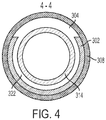
- Figure 4 depicts a cross-sectional view of assembly 300 along line 4-4.
- the sleeve 308 is exterior to the body 302 and at least part of the sleeve 308 is adjacent to the opening 304.
- the inner sleeve 314 is disposed in the inner area 310.
- the inner sleeve 314 can define the region 320 and the second region 322. Fluid (not illustrated) can be located in the second region 322.
- strings can be disposed in an inner area of casing strings.
- the strings can be capable of isolating sleeves from one or more types of pressures or forces.
- Figure 5 depicts a cross-sectional view of an embodiment of an assembly 400 that includes a body 402 with an opening 404 that is a pre-milled window in a sidewall.
- the assembly 400 includes a latch coupling 406 that can couple the assembly to other components of a casing string.
- a sleeve 408 is exterior to the body 402, with part of the sleeve 408 being adjacent to the opening 404.
- the sleeve 408 can cooperate with the body 402 to provide a pressure seal between an inner area 410 and an environment 412 exterior to the body 402.
- the sleeve 408 can be made from any material, such as a material having a high specific strength. Examples of such materials include carbon fiber, fiberglass, para-aramid synthetic fiber, silicon carbine, and carbon nanotubes.
- the assembly 400 also includes a string 414 disposed in the inner area 410.
- the string 414 may be made from any material, including from the same or from a different material than that from which the sleeve 408 is made. Examples of materials from which string 414 can be made include steel, titanium, and aluminum alloys.
- the string 414 can isolate the body 402 and sleeve 408 from tension and torsion forces by carrying such forces from one end 416 of the assembly 400 to a second end 418.
- the string 414 can be a permanent component of the assembly 400 disposed in the wellbore, or it can be retrievable after the assembly 400 is positioned.
- Figures 3 and 5 depict assemblies that include an inner sleeve or an inner string, but not both, certain assemblies can include both an inner sleeve and an inner string.
- Assemblies can reduce the load required on a casing string and can minimize the outer diameter of the casing string with a pre-milled window.
- a maximum outer diameter of a casing string with a pre-milled window may be 12.125 inches (30.8 cm) and the minimum outer diameter maybe 10.625 inches (27cm), providing 0.75 inches (1.9 cm) per side for a sleeve to be located to cover a pre-milled window.
- Sleeves made from a high specific strength material can reduce the thickness of the sleeves to allow the sleeves to cover the pre-milled windows and remaining in accordance with the diameter requirements.
- high specific strength sleeves used in combination with inner sleeves or inner string strings, can reduce or eliminate a need for the sleeve to be thick to hold torsion forces.
- sleeves By isolating the torque into inner sleeves or inner strings, sleeves only need to be thick enough to hold pressure (burst and collapse) and axial loads.
- the assembly may be provided as recited in the following numbered statements 1 to 20 (which statements are not to be considered as claims).
Landscapes
- Geology (AREA)
- Life Sciences & Earth Sciences (AREA)
- Engineering & Computer Science (AREA)
- Mining & Mineral Resources (AREA)
- Environmental & Geological Engineering (AREA)
- Fluid Mechanics (AREA)
- Physics & Mathematics (AREA)
- General Life Sciences & Earth Sciences (AREA)
- Geochemistry & Mineralogy (AREA)
- Earth Drilling (AREA)
- Filling Or Discharging Of Gas Storage Vessels (AREA)
- Devices Affording Protection Of Roads Or Walls For Sound Insulation (AREA)
- Gasket Seals (AREA)
Applications Claiming Priority (3)
| Application Number | Priority Date | Filing Date | Title |
|---|---|---|---|
| US12/726,717 US8602097B2 (en) | 2010-03-18 | 2010-03-18 | Well assembly with a composite fiber sleeve for an opening |
| EP11756687.7A EP2547860B8 (fr) | 2010-03-18 | 2011-02-08 | Ensemble puits à manchon en fibre composite pour une ouverture |
| PCT/US2011/023956 WO2011115710A2 (fr) | 2010-03-18 | 2011-02-08 | Ensemble puits à manchon en fibre composite pour une ouverture |
Related Parent Applications (2)
| Application Number | Title | Priority Date | Filing Date |
|---|---|---|---|
| EP11756687.7A Division-Into EP2547860B8 (fr) | 2010-03-18 | 2011-02-08 | Ensemble puits à manchon en fibre composite pour une ouverture |
| EP11756687.7A Division EP2547860B8 (fr) | 2010-03-18 | 2011-02-08 | Ensemble puits à manchon en fibre composite pour une ouverture |
Publications (2)
| Publication Number | Publication Date |
|---|---|
| EP3203011A1 true EP3203011A1 (fr) | 2017-08-09 |
| EP3203011B1 EP3203011B1 (fr) | 2019-02-27 |
Family
ID=44646294
Family Applications (2)
| Application Number | Title | Priority Date | Filing Date |
|---|---|---|---|
| EP11756687.7A Not-in-force EP2547860B8 (fr) | 2010-03-18 | 2011-02-08 | Ensemble puits à manchon en fibre composite pour une ouverture |
| EP17158211.7A Active EP3203011B1 (fr) | 2010-03-18 | 2011-02-08 | Ensemble puits à manchon en fibre composite pour une ouverture |
Family Applications Before (1)
| Application Number | Title | Priority Date | Filing Date |
|---|---|---|---|
| EP11756687.7A Not-in-force EP2547860B8 (fr) | 2010-03-18 | 2011-02-08 | Ensemble puits à manchon en fibre composite pour une ouverture |
Country Status (6)
| Country | Link |
|---|---|
| US (1) | US8602097B2 (fr) |
| EP (2) | EP2547860B8 (fr) |
| AU (1) | AU2011227712B2 (fr) |
| BR (1) | BR112012023529B1 (fr) |
| CA (1) | CA2792999C (fr) |
| WO (1) | WO2011115710A2 (fr) |
Families Citing this family (5)
| Publication number | Priority date | Publication date | Assignee | Title |
|---|---|---|---|---|
| CA2893130C (fr) | 2013-01-18 | 2017-09-12 | Halliburton Energy Services, Inc. | Systemes et procedes de support de fenetre multilaterale |
| CN105658904A (zh) * | 2013-11-08 | 2016-06-08 | 哈里伯顿能源服务公司 | 具有复合材料覆层的预磨铣窗 |
| US10605013B2 (en) | 2015-10-23 | 2020-03-31 | Halliburton Energy Services, Inc. | Casing string assembly with composite pre-milled window |
| WO2021030043A1 (fr) | 2019-08-13 | 2021-02-18 | Halliburton Energy Services, Inc. | Ensemble fenêtre forable permettant de commander la géométrie d'une jonction de puits de forage multilatéral |
| US12012854B2 (en) * | 2022-11-16 | 2024-06-18 | Saudi Arabian Oil Company | Sidetrack casing assembly for drilling sidetrack wellbores |
Citations (3)
| Publication number | Priority date | Publication date | Assignee | Title |
|---|---|---|---|---|
| GB2302702A (en) * | 1995-06-29 | 1997-01-29 | Baroid Technology Inc | Internal pressure sleeve for use with well casing having easily drillable exit ports |
| US6041855A (en) * | 1998-04-23 | 2000-03-28 | Halliburton Energy Services, Inc. | High torque pressure sleeve for easily drillable casing exit ports |
| GB2368862A (en) * | 2000-11-10 | 2002-05-15 | Smith International | Multilateral junction |
Family Cites Families (27)
| Publication number | Priority date | Publication date | Assignee | Title |
|---|---|---|---|---|
| US2994378A (en) * | 1957-03-13 | 1961-08-01 | Jersey Prod Res Co | Treatment of a well with the drill string in the well |
| US3926254A (en) * | 1974-12-20 | 1975-12-16 | Halliburton Co | Down-hole pump and inflatable packer apparatus |
| US4890675A (en) | 1989-03-08 | 1990-01-02 | Dew Edward G | Horizontal drilling through casing window |
| US5340626A (en) * | 1991-08-16 | 1994-08-23 | Head Philip F | Well packer |
| US5297640A (en) | 1992-10-29 | 1994-03-29 | Tom Jones | Drill collar for use in horizontal drilling |
| WO1995033910A1 (fr) * | 1994-06-09 | 1995-12-14 | Shell Internationale Research Maatschappij B.V. | Ensemble sifflet deviateur |
| US5564503A (en) | 1994-08-26 | 1996-10-15 | Halliburton Company | Methods and systems for subterranean multilateral well drilling and completion |
| US5579829A (en) | 1995-06-29 | 1996-12-03 | Baroid Technology, Inc. | Keyless latch for orienting and anchoring downhole tools |
| AU4330397A (en) | 1996-08-30 | 1998-03-19 | Baker Hughes Incorporated | Method and apparatus for sealing a junction on a multilateral well |
| US6012527A (en) | 1996-10-01 | 2000-01-11 | Schlumberger Technology Corporation | Method and apparatus for drilling and re-entering multiple lateral branched in a well |
| US6213228B1 (en) | 1997-08-08 | 2001-04-10 | Dresser Industries Inc. | Roller cone drill bit with improved pressure compensation |
| US6283208B1 (en) | 1997-09-05 | 2001-09-04 | Schlumberger Technology Corp. | Orienting tool and method |
| US6467557B1 (en) * | 1998-12-18 | 2002-10-22 | Western Well Tool, Inc. | Long reach rotary drilling assembly |
| CA2276222C (fr) | 1999-06-23 | 2002-09-03 | Halliburton Energy Services, Inc. | Manchon interne a haute pression utilisable avec des orifices de sortie faciles a forer |
| US6789621B2 (en) | 2000-08-03 | 2004-09-14 | Schlumberger Technology Corporation | Intelligent well system and method |
| US6811189B1 (en) | 2000-10-04 | 2004-11-02 | Grant Prideco, L.P. | Corrosion seal for threaded connections |
| US6868909B2 (en) | 2001-06-26 | 2005-03-22 | Baker Hughes Incorporated | Drillable junction joint and method of use |
| US6913082B2 (en) | 2003-02-28 | 2005-07-05 | Halliburton Energy Services, Inc. | Reduced debris milled multilateral window |
| US7213652B2 (en) | 2004-01-29 | 2007-05-08 | Halliburton Energy Services, Inc. | Sealed branch wellbore transition joint |
| US7225875B2 (en) | 2004-02-06 | 2007-06-05 | Halliburton Energy Services, Inc. | Multi-layered wellbore junction |
| CA2610369A1 (fr) | 2005-04-21 | 2006-11-02 | Baker Hughes Incorporated | Systeme lateral de commande |
| US20090045974A1 (en) | 2007-08-14 | 2009-02-19 | Schlumberger Technology Corporation | Short Hop Wireless Telemetry for Completion Systems |
| CA2720829C (fr) | 2008-05-04 | 2014-07-08 | Aquatic Company | Assemblage de colonne montante en aluminium |
| US9260921B2 (en) * | 2008-05-20 | 2016-02-16 | Halliburton Energy Services, Inc. | System and methods for constructing and fracture stimulating multiple ultra-short radius laterals from a parent well |
| US7726401B2 (en) | 2008-05-21 | 2010-06-01 | Halliburton Energy Services, Inc. | Casing exit joint with easily milled, low density barrier |
| US7703524B2 (en) | 2008-05-21 | 2010-04-27 | Halliburton Energy Services, Inc. | Cutting windows for lateral wellbore drilling |
| US20100051269A1 (en) | 2008-08-29 | 2010-03-04 | Welldynamics, Inc. | Bypass of damaged lines in subterranean wells |
-
2010
- 2010-03-18 US US12/726,717 patent/US8602097B2/en not_active Expired - Fee Related
-
2011
- 2011-02-08 BR BR112012023529A patent/BR112012023529B1/pt not_active IP Right Cessation
- 2011-02-08 WO PCT/US2011/023956 patent/WO2011115710A2/fr not_active Ceased
- 2011-02-08 AU AU2011227712A patent/AU2011227712B2/en not_active Ceased
- 2011-02-08 EP EP11756687.7A patent/EP2547860B8/fr not_active Not-in-force
- 2011-02-08 CA CA2792999A patent/CA2792999C/fr active Active
- 2011-02-08 EP EP17158211.7A patent/EP3203011B1/fr active Active
Patent Citations (3)
| Publication number | Priority date | Publication date | Assignee | Title |
|---|---|---|---|---|
| GB2302702A (en) * | 1995-06-29 | 1997-01-29 | Baroid Technology Inc | Internal pressure sleeve for use with well casing having easily drillable exit ports |
| US6041855A (en) * | 1998-04-23 | 2000-03-28 | Halliburton Energy Services, Inc. | High torque pressure sleeve for easily drillable casing exit ports |
| GB2368862A (en) * | 2000-11-10 | 2002-05-15 | Smith International | Multilateral junction |
Also Published As
| Publication number | Publication date |
|---|---|
| US20110226467A1 (en) | 2011-09-22 |
| EP2547860B1 (fr) | 2017-04-19 |
| US8602097B2 (en) | 2013-12-10 |
| AU2011227712B2 (en) | 2014-06-26 |
| WO2011115710A8 (fr) | 2012-04-05 |
| BR112012023529A2 (pt) | 2016-07-26 |
| EP2547860A4 (fr) | 2015-11-04 |
| AU2011227712A1 (en) | 2012-10-11 |
| EP3203011B1 (fr) | 2019-02-27 |
| EP2547860A2 (fr) | 2013-01-23 |
| WO2011115710A3 (fr) | 2011-12-01 |
| CA2792999C (fr) | 2014-10-28 |
| EP2547860B8 (fr) | 2017-06-28 |
| CA2792999A1 (fr) | 2011-09-22 |
| WO2011115710A2 (fr) | 2011-09-22 |
| BR112012023529B1 (pt) | 2019-12-10 |
Similar Documents
| Publication | Publication Date | Title |
|---|---|---|
| AU2011201101B2 (en) | Well assembly with recesses facilitating branch wellbore creation | |
| EP3492690A1 (fr) | Ensemble de jonction de forages multiples à haute pression | |
| CN104870743B (zh) | 支撑多分支窗的系统和方法 | |
| US6913082B2 (en) | Reduced debris milled multilateral window | |
| EP2547860B1 (fr) | Ensemble puits à manchon en fibre composite pour une ouverture | |
| CA2734376C (fr) | Assemblage de puits muni d'un element usinable dans une ouverture | |
| AU2011236065B2 (en) | System and method for opening a window in a casing string for multilateral wellbore construction | |
| US8727022B2 (en) | Systems and methods of supporting a multilateral window | |
| EP3071783B1 (fr) | Ensemble déflecteur de puits doté d'un dispositif de joint annulaire sensiblement équilibré en pression | |
| CA2961566C (fr) | Ensemble siege reglable |
Legal Events
| Date | Code | Title | Description |
|---|---|---|---|
| PUAI | Public reference made under article 153(3) epc to a published international application that has entered the european phase |
Free format text: ORIGINAL CODE: 0009012 |
|
| STAA | Information on the status of an ep patent application or granted ep patent |
Free format text: STATUS: THE APPLICATION HAS BEEN PUBLISHED |
|
| AC | Divisional application: reference to earlier application |
Ref document number: 2547860 Country of ref document: EP Kind code of ref document: P |
|
| AK | Designated contracting states |
Kind code of ref document: A1 Designated state(s): AL AT BE BG CH CY CZ DE DK EE ES FI FR GB GR HR HU IE IS IT LI LT LU LV MC MK MT NL NO PL PT RO RS SE SI SK SM TR |
|
| STAA | Information on the status of an ep patent application or granted ep patent |
Free format text: STATUS: REQUEST FOR EXAMINATION WAS MADE |
|
| 17P | Request for examination filed |
Effective date: 20180205 |
|
| RBV | Designated contracting states (corrected) |
Designated state(s): AL AT BE BG CH CY CZ DE DK EE ES FI FR GB GR HR HU IE IS IT LI LT LU LV MC MK MT NL NO PL PT RO RS SE SI SK SM TR |
|
| GRAP | Despatch of communication of intention to grant a patent |
Free format text: ORIGINAL CODE: EPIDOSNIGR1 |
|
| STAA | Information on the status of an ep patent application or granted ep patent |
Free format text: STATUS: GRANT OF PATENT IS INTENDED |
|
| INTG | Intention to grant announced |
Effective date: 20181022 |
|
| GRAS | Grant fee paid |
Free format text: ORIGINAL CODE: EPIDOSNIGR3 |
|
| GRAA | (expected) grant |
Free format text: ORIGINAL CODE: 0009210 |
|
| STAA | Information on the status of an ep patent application or granted ep patent |
Free format text: STATUS: THE PATENT HAS BEEN GRANTED |
|
| AC | Divisional application: reference to earlier application |
Ref document number: 2547860 Country of ref document: EP Kind code of ref document: P |
|
| AK | Designated contracting states |
Kind code of ref document: B1 Designated state(s): AL AT BE BG CH CY CZ DE DK EE ES FI FR GB GR HR HU IE IS IT LI LT LU LV MC MK MT NL NO PL PT RO RS SE SI SK SM TR |
|
| REG | Reference to a national code |
Ref country code: GB Ref legal event code: FG4D |
|
| REG | Reference to a national code |
Ref country code: CH Ref legal event code: EP |
|
| REG | Reference to a national code |
Ref country code: AT Ref legal event code: REF Ref document number: 1101610 Country of ref document: AT Kind code of ref document: T Effective date: 20190315 |
|
| REG | Reference to a national code |
Ref country code: IE Ref legal event code: FG4D |
|
| REG | Reference to a national code |
Ref country code: DE Ref legal event code: R096 Ref document number: 602011056785 Country of ref document: DE |
|
| REG | Reference to a national code |
Ref country code: NO Ref legal event code: T2 Effective date: 20190227 |
|
| REG | Reference to a national code |
Ref country code: NL Ref legal event code: MP Effective date: 20190227 |
|
| REG | Reference to a national code |
Ref country code: LT Ref legal event code: MG4D |
|
| PG25 | Lapsed in a contracting state [announced via postgrant information from national office to epo] |
Ref country code: PT Free format text: LAPSE BECAUSE OF FAILURE TO SUBMIT A TRANSLATION OF THE DESCRIPTION OR TO PAY THE FEE WITHIN THE PRESCRIBED TIME-LIMIT Effective date: 20190627 Ref country code: NL Free format text: LAPSE BECAUSE OF FAILURE TO SUBMIT A TRANSLATION OF THE DESCRIPTION OR TO PAY THE FEE WITHIN THE PRESCRIBED TIME-LIMIT Effective date: 20190227 Ref country code: LT Free format text: LAPSE BECAUSE OF FAILURE TO SUBMIT A TRANSLATION OF THE DESCRIPTION OR TO PAY THE FEE WITHIN THE PRESCRIBED TIME-LIMIT Effective date: 20190227 Ref country code: SE Free format text: LAPSE BECAUSE OF FAILURE TO SUBMIT A TRANSLATION OF THE DESCRIPTION OR TO PAY THE FEE WITHIN THE PRESCRIBED TIME-LIMIT Effective date: 20190227 Ref country code: FI Free format text: LAPSE BECAUSE OF FAILURE TO SUBMIT A TRANSLATION OF THE DESCRIPTION OR TO PAY THE FEE WITHIN THE PRESCRIBED TIME-LIMIT Effective date: 20190227 |
|
| PG25 | Lapsed in a contracting state [announced via postgrant information from national office to epo] |
Ref country code: GR Free format text: LAPSE BECAUSE OF FAILURE TO SUBMIT A TRANSLATION OF THE DESCRIPTION OR TO PAY THE FEE WITHIN THE PRESCRIBED TIME-LIMIT Effective date: 20190528 Ref country code: RS Free format text: LAPSE BECAUSE OF FAILURE TO SUBMIT A TRANSLATION OF THE DESCRIPTION OR TO PAY THE FEE WITHIN THE PRESCRIBED TIME-LIMIT Effective date: 20190227 Ref country code: IS Free format text: LAPSE BECAUSE OF FAILURE TO SUBMIT A TRANSLATION OF THE DESCRIPTION OR TO PAY THE FEE WITHIN THE PRESCRIBED TIME-LIMIT Effective date: 20190627 Ref country code: BG Free format text: LAPSE BECAUSE OF FAILURE TO SUBMIT A TRANSLATION OF THE DESCRIPTION OR TO PAY THE FEE WITHIN THE PRESCRIBED TIME-LIMIT Effective date: 20190527 Ref country code: LV Free format text: LAPSE BECAUSE OF FAILURE TO SUBMIT A TRANSLATION OF THE DESCRIPTION OR TO PAY THE FEE WITHIN THE PRESCRIBED TIME-LIMIT Effective date: 20190227 Ref country code: HR Free format text: LAPSE BECAUSE OF FAILURE TO SUBMIT A TRANSLATION OF THE DESCRIPTION OR TO PAY THE FEE WITHIN THE PRESCRIBED TIME-LIMIT Effective date: 20190227 |
|
| REG | Reference to a national code |
Ref country code: AT Ref legal event code: MK05 Ref document number: 1101610 Country of ref document: AT Kind code of ref document: T Effective date: 20190227 |
|
| PG25 | Lapsed in a contracting state [announced via postgrant information from national office to epo] |
Ref country code: SK Free format text: LAPSE BECAUSE OF FAILURE TO SUBMIT A TRANSLATION OF THE DESCRIPTION OR TO PAY THE FEE WITHIN THE PRESCRIBED TIME-LIMIT Effective date: 20190227 Ref country code: IT Free format text: LAPSE BECAUSE OF FAILURE TO SUBMIT A TRANSLATION OF THE DESCRIPTION OR TO PAY THE FEE WITHIN THE PRESCRIBED TIME-LIMIT Effective date: 20190227 Ref country code: RO Free format text: LAPSE BECAUSE OF FAILURE TO SUBMIT A TRANSLATION OF THE DESCRIPTION OR TO PAY THE FEE WITHIN THE PRESCRIBED TIME-LIMIT Effective date: 20190227 Ref country code: CZ Free format text: LAPSE BECAUSE OF FAILURE TO SUBMIT A TRANSLATION OF THE DESCRIPTION OR TO PAY THE FEE WITHIN THE PRESCRIBED TIME-LIMIT Effective date: 20190227 Ref country code: DK Free format text: LAPSE BECAUSE OF FAILURE TO SUBMIT A TRANSLATION OF THE DESCRIPTION OR TO PAY THE FEE WITHIN THE PRESCRIBED TIME-LIMIT Effective date: 20190227 Ref country code: AL Free format text: LAPSE BECAUSE OF FAILURE TO SUBMIT A TRANSLATION OF THE DESCRIPTION OR TO PAY THE FEE WITHIN THE PRESCRIBED TIME-LIMIT Effective date: 20190227 Ref country code: ES Free format text: LAPSE BECAUSE OF FAILURE TO SUBMIT A TRANSLATION OF THE DESCRIPTION OR TO PAY THE FEE WITHIN THE PRESCRIBED TIME-LIMIT Effective date: 20190227 Ref country code: EE Free format text: LAPSE BECAUSE OF FAILURE TO SUBMIT A TRANSLATION OF THE DESCRIPTION OR TO PAY THE FEE WITHIN THE PRESCRIBED TIME-LIMIT Effective date: 20190227 |
|
| REG | Reference to a national code |
Ref country code: DE Ref legal event code: R097 Ref document number: 602011056785 Country of ref document: DE |
|
| PG25 | Lapsed in a contracting state [announced via postgrant information from national office to epo] |
Ref country code: SM Free format text: LAPSE BECAUSE OF FAILURE TO SUBMIT A TRANSLATION OF THE DESCRIPTION OR TO PAY THE FEE WITHIN THE PRESCRIBED TIME-LIMIT Effective date: 20190227 Ref country code: PL Free format text: LAPSE BECAUSE OF FAILURE TO SUBMIT A TRANSLATION OF THE DESCRIPTION OR TO PAY THE FEE WITHIN THE PRESCRIBED TIME-LIMIT Effective date: 20190227 |
|
| PG25 | Lapsed in a contracting state [announced via postgrant information from national office to epo] |
Ref country code: AT Free format text: LAPSE BECAUSE OF FAILURE TO SUBMIT A TRANSLATION OF THE DESCRIPTION OR TO PAY THE FEE WITHIN THE PRESCRIBED TIME-LIMIT Effective date: 20190227 |
|
| PLBE | No opposition filed within time limit |
Free format text: ORIGINAL CODE: 0009261 |
|
| STAA | Information on the status of an ep patent application or granted ep patent |
Free format text: STATUS: NO OPPOSITION FILED WITHIN TIME LIMIT |
|
| 26N | No opposition filed |
Effective date: 20191128 |
|
| PG25 | Lapsed in a contracting state [announced via postgrant information from national office to epo] |
Ref country code: SI Free format text: LAPSE BECAUSE OF FAILURE TO SUBMIT A TRANSLATION OF THE DESCRIPTION OR TO PAY THE FEE WITHIN THE PRESCRIBED TIME-LIMIT Effective date: 20190227 |
|
| PG25 | Lapsed in a contracting state [announced via postgrant information from national office to epo] |
Ref country code: TR Free format text: LAPSE BECAUSE OF FAILURE TO SUBMIT A TRANSLATION OF THE DESCRIPTION OR TO PAY THE FEE WITHIN THE PRESCRIBED TIME-LIMIT Effective date: 20190227 |
|
| REG | Reference to a national code |
Ref country code: DE Ref legal event code: R119 Ref document number: 602011056785 Country of ref document: DE |
|
| REG | Reference to a national code |
Ref country code: CH Ref legal event code: PL |
|
| REG | Reference to a national code |
Ref country code: BE Ref legal event code: MM Effective date: 20200229 |
|
| PG25 | Lapsed in a contracting state [announced via postgrant information from national office to epo] |
Ref country code: MC Free format text: LAPSE BECAUSE OF FAILURE TO SUBMIT A TRANSLATION OF THE DESCRIPTION OR TO PAY THE FEE WITHIN THE PRESCRIBED TIME-LIMIT Effective date: 20190227 Ref country code: LU Free format text: LAPSE BECAUSE OF NON-PAYMENT OF DUE FEES Effective date: 20200208 |
|
| PG25 | Lapsed in a contracting state [announced via postgrant information from national office to epo] |
Ref country code: CH Free format text: LAPSE BECAUSE OF NON-PAYMENT OF DUE FEES Effective date: 20200229 Ref country code: LI Free format text: LAPSE BECAUSE OF NON-PAYMENT OF DUE FEES Effective date: 20200229 |
|
| PG25 | Lapsed in a contracting state [announced via postgrant information from national office to epo] |
Ref country code: FR Free format text: LAPSE BECAUSE OF NON-PAYMENT OF DUE FEES Effective date: 20200229 Ref country code: IE Free format text: LAPSE BECAUSE OF NON-PAYMENT OF DUE FEES Effective date: 20200208 Ref country code: DE Free format text: LAPSE BECAUSE OF NON-PAYMENT OF DUE FEES Effective date: 20200901 |
|
| PG25 | Lapsed in a contracting state [announced via postgrant information from national office to epo] |
Ref country code: BE Free format text: LAPSE BECAUSE OF NON-PAYMENT OF DUE FEES Effective date: 20200229 |
|
| PG25 | Lapsed in a contracting state [announced via postgrant information from national office to epo] |
Ref country code: MT Free format text: LAPSE BECAUSE OF FAILURE TO SUBMIT A TRANSLATION OF THE DESCRIPTION OR TO PAY THE FEE WITHIN THE PRESCRIBED TIME-LIMIT Effective date: 20190227 Ref country code: CY Free format text: LAPSE BECAUSE OF FAILURE TO SUBMIT A TRANSLATION OF THE DESCRIPTION OR TO PAY THE FEE WITHIN THE PRESCRIBED TIME-LIMIT Effective date: 20190227 |
|
| PG25 | Lapsed in a contracting state [announced via postgrant information from national office to epo] |
Ref country code: MK Free format text: LAPSE BECAUSE OF FAILURE TO SUBMIT A TRANSLATION OF THE DESCRIPTION OR TO PAY THE FEE WITHIN THE PRESCRIBED TIME-LIMIT Effective date: 20190227 |
|
| PGFP | Annual fee paid to national office [announced via postgrant information from national office to epo] |
Ref country code: GB Payment date: 20221201 Year of fee payment: 13 |
|
| PGFP | Annual fee paid to national office [announced via postgrant information from national office to epo] |
Ref country code: NO Payment date: 20230120 Year of fee payment: 13 |
|
| GBPC | Gb: european patent ceased through non-payment of renewal fee |
Effective date: 20240208 |
|
| PG25 | Lapsed in a contracting state [announced via postgrant information from national office to epo] |
Ref country code: NO Free format text: LAPSE BECAUSE OF NON-PAYMENT OF DUE FEES Effective date: 20240229 |
|
| PG25 | Lapsed in a contracting state [announced via postgrant information from national office to epo] |
Ref country code: GB Free format text: LAPSE BECAUSE OF NON-PAYMENT OF DUE FEES Effective date: 20240208 |
|
| PG25 | Lapsed in a contracting state [announced via postgrant information from national office to epo] |
Ref country code: GB Free format text: LAPSE BECAUSE OF NON-PAYMENT OF DUE FEES Effective date: 20240208 |