EP3203014A1 - Système et procédé de complétion, procédé d'exploration de puits de forage, utilisation de ceux-ci dans l'exploration/extraction de puits de forage, capsule de conditionnement, joint télescopique, vanne et procédé d'isolation et système d'actionnement de celle-ci, vanne sélectrice et son utilisation, et raccord et joint de dilatation électro-hydraulique - Google Patents
Système et procédé de complétion, procédé d'exploration de puits de forage, utilisation de ceux-ci dans l'exploration/extraction de puits de forage, capsule de conditionnement, joint télescopique, vanne et procédé d'isolation et système d'actionnement de celle-ci, vanne sélectrice et son utilisation, et raccord et joint de dilatation électro-hydraulique Download PDFInfo
- Publication number
- EP3203014A1 EP3203014A1 EP15846958.5A EP15846958A EP3203014A1 EP 3203014 A1 EP3203014 A1 EP 3203014A1 EP 15846958 A EP15846958 A EP 15846958A EP 3203014 A1 EP3203014 A1 EP 3203014A1
- Authority
- EP
- European Patent Office
- Prior art keywords
- valve
- hydraulic
- capsule
- drilled
- drilled well
- Prior art date
- Legal status (The legal status is an assumption and is not a legal conclusion. Google has not performed a legal analysis and makes no representation as to the accuracy of the status listed.)
- Withdrawn
Links
- 239000002775 capsule Substances 0.000 title claims description 101
- 238000000034 method Methods 0.000 title claims description 31
- 238000000605 extraction Methods 0.000 title claims description 16
- 238000004806 packaging method and process Methods 0.000 title claims description 7
- 238000009413 insulation Methods 0.000 title description 3
- 230000007246 mechanism Effects 0.000 claims abstract description 30
- 239000012530 fluid Substances 0.000 claims description 102
- 238000004519 manufacturing process Methods 0.000 claims description 76
- 238000000576 coating method Methods 0.000 claims description 30
- 239000011248 coating agent Substances 0.000 claims description 29
- 238000007789 sealing Methods 0.000 claims description 27
- 230000015572 biosynthetic process Effects 0.000 claims description 19
- 238000005755 formation reaction Methods 0.000 claims description 19
- 230000008878 coupling Effects 0.000 claims description 15
- 238000010168 coupling process Methods 0.000 claims description 15
- 238000005859 coupling reaction Methods 0.000 claims description 15
- 229930195733 hydrocarbon Natural products 0.000 claims description 11
- 150000002430 hydrocarbons Chemical class 0.000 claims description 10
- 238000012423 maintenance Methods 0.000 claims description 10
- 229920001971 elastomer Polymers 0.000 claims description 7
- 239000000806 elastomer Substances 0.000 claims description 7
- 230000007423 decrease Effects 0.000 claims description 6
- 230000005540 biological transmission Effects 0.000 claims description 5
- 230000002093 peripheral effect Effects 0.000 claims description 4
- 239000003208 petroleum Substances 0.000 abstract description 9
- 238000009434 installation Methods 0.000 abstract description 2
- 239000007789 gas Substances 0.000 description 32
- 238000005086 pumping Methods 0.000 description 24
- 239000000523 sample Substances 0.000 description 14
- 230000000712 assembly Effects 0.000 description 10
- 238000000429 assembly Methods 0.000 description 10
- 230000004087 circulation Effects 0.000 description 10
- 230000001276 controlling effect Effects 0.000 description 9
- 238000011084 recovery Methods 0.000 description 8
- 230000008901 benefit Effects 0.000 description 7
- 239000000126 substance Substances 0.000 description 7
- IJGRMHOSHXDMSA-UHFFFAOYSA-N Atomic nitrogen Chemical compound N#N IJGRMHOSHXDMSA-UHFFFAOYSA-N 0.000 description 6
- 238000004140 cleaning Methods 0.000 description 6
- 238000004891 communication Methods 0.000 description 6
- 239000007788 liquid Substances 0.000 description 5
- 230000008569 process Effects 0.000 description 5
- 238000002347 injection Methods 0.000 description 4
- 239000007924 injection Substances 0.000 description 4
- 210000000281 joint capsule Anatomy 0.000 description 4
- 239000002184 metal Substances 0.000 description 4
- 239000000203 mixture Substances 0.000 description 4
- 230000001012 protector Effects 0.000 description 4
- 230000001174 ascending effect Effects 0.000 description 3
- 230000014759 maintenance of location Effects 0.000 description 3
- 229910052757 nitrogen Inorganic materials 0.000 description 3
- 239000012466 permeate Substances 0.000 description 3
- 239000011435 rock Substances 0.000 description 3
- 238000005204 segregation Methods 0.000 description 3
- 239000007787 solid Substances 0.000 description 3
- 238000011144 upstream manufacturing Methods 0.000 description 3
- 241000251468 Actinopterygii Species 0.000 description 2
- 239000004215 Carbon black (E152) Substances 0.000 description 2
- 230000009471 action Effects 0.000 description 2
- 230000008859 change Effects 0.000 description 2
- 230000008602 contraction Effects 0.000 description 2
- 238000013016 damping Methods 0.000 description 2
- 238000012544 monitoring process Methods 0.000 description 2
- 230000001737 promoting effect Effects 0.000 description 2
- 239000000243 solution Substances 0.000 description 2
- 239000013589 supplement Substances 0.000 description 2
- 238000012360 testing method Methods 0.000 description 2
- XLYOFNOQVPJJNP-UHFFFAOYSA-N water Substances O XLYOFNOQVPJJNP-UHFFFAOYSA-N 0.000 description 2
- 238000003466 welding Methods 0.000 description 2
- 208000007514 Herpes zoster Diseases 0.000 description 1
- 230000001133 acceleration Effects 0.000 description 1
- 239000010426 asphalt Substances 0.000 description 1
- 230000004888 barrier function Effects 0.000 description 1
- 230000033228 biological regulation Effects 0.000 description 1
- 230000000903 blocking effect Effects 0.000 description 1
- 238000011109 contamination Methods 0.000 description 1
- 230000007812 deficiency Effects 0.000 description 1
- 238000011161 development Methods 0.000 description 1
- 238000006073 displacement reaction Methods 0.000 description 1
- 230000000694 effects Effects 0.000 description 1
- 230000008030 elimination Effects 0.000 description 1
- 238000003379 elimination reaction Methods 0.000 description 1
- 238000005516 engineering process Methods 0.000 description 1
- 238000001914 filtration Methods 0.000 description 1
- 125000001183 hydrocarbyl group Chemical group 0.000 description 1
- 230000001939 inductive effect Effects 0.000 description 1
- 239000000463 material Substances 0.000 description 1
- 230000000116 mitigating effect Effects 0.000 description 1
- 239000003921 oil Substances 0.000 description 1
- 239000003129 oil well Substances 0.000 description 1
- 238000003825 pressing Methods 0.000 description 1
- 238000012545 processing Methods 0.000 description 1
- 239000000047 product Substances 0.000 description 1
- 230000001105 regulatory effect Effects 0.000 description 1
- 238000000926 separation method Methods 0.000 description 1
- 230000008093 supporting effect Effects 0.000 description 1
- 230000008961 swelling Effects 0.000 description 1
- 238000012546 transfer Methods 0.000 description 1
Images










Classifications
-
- E—FIXED CONSTRUCTIONS
- E21—EARTH OR ROCK DRILLING; MINING
- E21B—EARTH OR ROCK DRILLING; OBTAINING OIL, GAS, WATER, SOLUBLE OR MELTABLE MATERIALS OR A SLURRY OF MINERALS FROM WELLS
- E21B34/00—Valve arrangements for boreholes or wells
- E21B34/06—Valve arrangements for boreholes or wells in wells
- E21B34/10—Valve arrangements for boreholes or wells in wells operated by control fluid supplied from outside the borehole
-
- E—FIXED CONSTRUCTIONS
- E21—EARTH OR ROCK DRILLING; MINING
- E21B—EARTH OR ROCK DRILLING; OBTAINING OIL, GAS, WATER, SOLUBLE OR MELTABLE MATERIALS OR A SLURRY OF MINERALS FROM WELLS
- E21B7/00—Special methods or apparatus for drilling
- E21B7/20—Driving or forcing casings or pipes into boreholes, e.g. sinking; Simultaneously drilling and casing boreholes
- E21B7/201—Driving or forcing casings or pipes into boreholes, e.g. sinking; Simultaneously drilling and casing boreholes with helical conveying means
- E21B7/203—Driving or forcing casings or pipes into boreholes, e.g. sinking; Simultaneously drilling and casing boreholes with helical conveying means using down-hole drives
-
- E—FIXED CONSTRUCTIONS
- E21—EARTH OR ROCK DRILLING; MINING
- E21B—EARTH OR ROCK DRILLING; OBTAINING OIL, GAS, WATER, SOLUBLE OR MELTABLE MATERIALS OR A SLURRY OF MINERALS FROM WELLS
- E21B17/00—Drilling rods or pipes; Flexible drill strings; Kellies; Drill collars; Sucker rods; Cables; Casings; Tubings
- E21B17/22—Rods or pipes with helical structure
-
- E—FIXED CONSTRUCTIONS
- E21—EARTH OR ROCK DRILLING; MINING
- E21B—EARTH OR ROCK DRILLING; OBTAINING OIL, GAS, WATER, SOLUBLE OR MELTABLE MATERIALS OR A SLURRY OF MINERALS FROM WELLS
- E21B33/00—Sealing or packing boreholes or wells
- E21B33/02—Surface sealing or packing
- E21B33/03—Well heads; Setting-up thereof
- E21B33/035—Well heads; Setting-up thereof specially adapted for underwater installations
- E21B33/0355—Control systems, e.g. hydraulic, pneumatic, electric, acoustic, for submerged well heads
-
- E—FIXED CONSTRUCTIONS
- E21—EARTH OR ROCK DRILLING; MINING
- E21B—EARTH OR ROCK DRILLING; OBTAINING OIL, GAS, WATER, SOLUBLE OR MELTABLE MATERIALS OR A SLURRY OF MINERALS FROM WELLS
- E21B41/00—Equipment or details not covered by groups E21B15/00 - E21B40/00
- E21B41/0021—Safety devices, e.g. for preventing small objects from falling into the borehole
-
- E—FIXED CONSTRUCTIONS
- E21—EARTH OR ROCK DRILLING; MINING
- E21B—EARTH OR ROCK DRILLING; OBTAINING OIL, GAS, WATER, SOLUBLE OR MELTABLE MATERIALS OR A SLURRY OF MINERALS FROM WELLS
- E21B43/00—Methods or apparatus for obtaining oil, gas, water, soluble or meltable materials or a slurry of minerals from wells
- E21B43/02—Subsoil filtering
- E21B43/10—Setting of casings, screens, liners or the like in wells
- E21B43/103—Setting of casings, screens, liners or the like in wells of expandable casings, screens, liners, or the like
- E21B43/106—Couplings or joints therefor
-
- E—FIXED CONSTRUCTIONS
- E21—EARTH OR ROCK DRILLING; MINING
- E21B—EARTH OR ROCK DRILLING; OBTAINING OIL, GAS, WATER, SOLUBLE OR MELTABLE MATERIALS OR A SLURRY OF MINERALS FROM WELLS
- E21B43/00—Methods or apparatus for obtaining oil, gas, water, soluble or meltable materials or a slurry of minerals from wells
- E21B43/12—Methods or apparatus for controlling the flow of the obtained fluid to or in wells
-
- E—FIXED CONSTRUCTIONS
- E21—EARTH OR ROCK DRILLING; MINING
- E21B—EARTH OR ROCK DRILLING; OBTAINING OIL, GAS, WATER, SOLUBLE OR MELTABLE MATERIALS OR A SLURRY OF MINERALS FROM WELLS
- E21B43/00—Methods or apparatus for obtaining oil, gas, water, soluble or meltable materials or a slurry of minerals from wells
- E21B43/12—Methods or apparatus for controlling the flow of the obtained fluid to or in wells
- E21B43/121—Lifting well fluids
- E21B43/122—Gas lift
- E21B43/123—Gas lift valves
-
- E—FIXED CONSTRUCTIONS
- E21—EARTH OR ROCK DRILLING; MINING
- E21B—EARTH OR ROCK DRILLING; OBTAINING OIL, GAS, WATER, SOLUBLE OR MELTABLE MATERIALS OR A SLURRY OF MINERALS FROM WELLS
- E21B43/00—Methods or apparatus for obtaining oil, gas, water, soluble or meltable materials or a slurry of minerals from wells
- E21B43/12—Methods or apparatus for controlling the flow of the obtained fluid to or in wells
- E21B43/121—Lifting well fluids
- E21B43/128—Adaptation of pump systems with down-hole electric drives
-
- E—FIXED CONSTRUCTIONS
- E21—EARTH OR ROCK DRILLING; MINING
- E21B—EARTH OR ROCK DRILLING; OBTAINING OIL, GAS, WATER, SOLUBLE OR MELTABLE MATERIALS OR A SLURRY OF MINERALS FROM WELLS
- E21B47/00—Survey of boreholes or wells
-
- E—FIXED CONSTRUCTIONS
- E21—EARTH OR ROCK DRILLING; MINING
- E21B—EARTH OR ROCK DRILLING; OBTAINING OIL, GAS, WATER, SOLUBLE OR MELTABLE MATERIALS OR A SLURRY OF MINERALS FROM WELLS
- E21B7/00—Special methods or apparatus for drilling
- E21B7/04—Directional drilling
-
- F—MECHANICAL ENGINEERING; LIGHTING; HEATING; WEAPONS; BLASTING
- F04—POSITIVE - DISPLACEMENT MACHINES FOR LIQUIDS; PUMPS FOR LIQUIDS OR ELASTIC FLUIDS
- F04D—NON-POSITIVE-DISPLACEMENT PUMPS
- F04D13/00—Pumping installations or systems
- F04D13/02—Units comprising pumps and their driving means
- F04D13/06—Units comprising pumps and their driving means the pump being electrically driven
- F04D13/08—Units comprising pumps and their driving means the pump being electrically driven for submerged use
- F04D13/10—Units comprising pumps and their driving means the pump being electrically driven for submerged use adapted for use in mining bore holes
-
- F—MECHANICAL ENGINEERING; LIGHTING; HEATING; WEAPONS; BLASTING
- F16—ENGINEERING ELEMENTS AND UNITS; GENERAL MEASURES FOR PRODUCING AND MAINTAINING EFFECTIVE FUNCTIONING OF MACHINES OR INSTALLATIONS; THERMAL INSULATION IN GENERAL
- F16K—VALVES; TAPS; COCKS; ACTUATING-FLOATS; DEVICES FOR VENTING OR AERATING
- F16K15/00—Check valves
-
- F—MECHANICAL ENGINEERING; LIGHTING; HEATING; WEAPONS; BLASTING
- F16—ENGINEERING ELEMENTS AND UNITS; GENERAL MEASURES FOR PRODUCING AND MAINTAINING EFFECTIVE FUNCTIONING OF MACHINES OR INSTALLATIONS; THERMAL INSULATION IN GENERAL
- F16K—VALVES; TAPS; COCKS; ACTUATING-FLOATS; DEVICES FOR VENTING OR AERATING
- F16K31/00—Actuating devices; Operating means; Releasing devices
- F16K31/12—Actuating devices; Operating means; Releasing devices actuated by fluid
-
- F—MECHANICAL ENGINEERING; LIGHTING; HEATING; WEAPONS; BLASTING
- F16—ENGINEERING ELEMENTS AND UNITS; GENERAL MEASURES FOR PRODUCING AND MAINTAINING EFFECTIVE FUNCTIONING OF MACHINES OR INSTALLATIONS; THERMAL INSULATION IN GENERAL
- F16L—PIPES; JOINTS OR FITTINGS FOR PIPES; SUPPORTS FOR PIPES, CABLES OR PROTECTIVE TUBING; MEANS FOR THERMAL INSULATION IN GENERAL
- F16L27/00—Adjustable joints; Joints allowing movement
-
- E—FIXED CONSTRUCTIONS
- E21—EARTH OR ROCK DRILLING; MINING
- E21B—EARTH OR ROCK DRILLING; OBTAINING OIL, GAS, WATER, SOLUBLE OR MELTABLE MATERIALS OR A SLURRY OF MINERALS FROM WELLS
- E21B43/00—Methods or apparatus for obtaining oil, gas, water, soluble or meltable materials or a slurry of minerals from wells
-
- E—FIXED CONSTRUCTIONS
- E21—EARTH OR ROCK DRILLING; MINING
- E21B—EARTH OR ROCK DRILLING; OBTAINING OIL, GAS, WATER, SOLUBLE OR MELTABLE MATERIALS OR A SLURRY OF MINERALS FROM WELLS
- E21B47/00—Survey of boreholes or wells
- E21B47/01—Devices for supporting measuring instruments on drill bits, pipes, rods or wirelines; Protecting measuring instruments in boreholes against heat, shock, pressure or the like
Definitions
- the present invention refers to an exploration system of drilled wells and a method for extracting fluids from the said drilled wells.
- the present invention is in the fields of petroleum engineering, and mechanic engineering.
- the smart completion of oil producing wells is a type of completion that allows producing several producing zones together, monitoring and controlling the said producing zones remotely and individually.
- the use of smart completion enables exploration of marginal reserves and acceleration of hydrocarbon production through joint and controlled production of reservoirs, significantly increasing the recovery factor of the field.
- the average useful life of BCS is 2 years. That is, in this average time interval, a probe workover must occur for BCS replacement that has stopped working. This workover lasts an average of 45 days and, in addition to the high expenses with "probe diaries", it is necessary to internalize the time that the well has stopped producing (loss of profit), awaiting probe for workover. To minimize this, the well is usually equipped with BCS and gas-lift mandrel, which will start as soon as the pump stops working, while the probe does not reach. This time can be long and depends on the demand for probes in the period demanded.
- Document CN103382835 discloses one completion system of multiple producing zones provided with packers separating the said producing zones in order to provide a segregation between the said producing zones.
- Each producing zone has one smart control device, for example, the first producing zone is controlled by one first smart control device, the second producing zone is controlled by a second smart control device, and so on.
- the production column is associated to all producing zones, but it produces fluids only from that zone where the system decides to produce.
- This invention's teachings refer on an automated system to detect which zones is producing fluids with less amount of undesired fluids mixed to the fluids of interest.
- Document US8127845 discloses a completion system of multiple producing zones of hydrocarbons based on the selective segregation of zones that will produce fluids.
- the operator commanding a rod of service is able to isolate a producing zone misaligning the holes present in the inner capsule of the holes present in the outer tube, while when it is desired to produce from another producing zone, this same operator aligns the said holes such that the fluids may move up through the production column.
- the said alignment and misalignment of holes is made with the service rod and its outer recess that, in contact with the inner recess present in the sliding sleeve transmits the axial movement axial of the service rod in order to align or misalign holes.
- This document discloses some facilities in the completions, since it is possible to produce several producing zones in a joint or separated manner. For example, if in a certain producing zone the pressure is too higher regarding a second producing zone, it is possible to produce from this producing zone of greater pressure until pressures are balanced, and the hydrocarbons formation occurs simultaneously between several producing zones. Further, it is possible to drain undesired fluids (water, mud, etc) of a certain producing zone, while the further ones are closed, avoiding possible contamination.
- This document does not disclose a form to reduce the workover time of oil producer wells, mainly those provided with smart completions. Such document also does not disclose a mean to remove the submerged centrifugal pumping assembly in wells with smart completion without the risk of complex and onerous fisheries.
- Document US20140083684 discloses a completion system of hydrocarbons producing wells that permeate through multiple formation.
- the system is based on packers dividing multiple formation zones and, through a pressure sensor analyzing the pressure in the said formation zone send collected information through the cable. The said information is used to control the flow that is formed from each one of the production zones.
- Conventional equipments of a completion include gravel, pressure sensor, filtering screen and, mainly, a flow control valve driven by one hydraulic control.
- the flow control valve is able to totally close the formation zone, or simply restrict part of the production flow, according to the moment needs.
- the system of the present document has also a device for pumping the production flow, safety valve and formation total isolating valve. The said document does not disclose how to produce multiple formation zones reconciling the minimum need of workover with probe, using the submerged centrifugal pumping equipment, with short lifespan.
- the capsule does not have any facility when removing the pump assembly, a further point away from the present invention is the fact that the said capsule comes out of the oil well to replace the pump assembly, since this capsule is joint with the remainder of the assembly.
- Document US7150325 has a system of submerged pump comprising a primary coating capsule having internally a capsule of main housing, an inner pump to this and an outer casing involving the said primary coating in order to form an annular space.
- the primary capsule has in its lower end a polished hole with a sleeve or flapper type valve.
- the primary coating capsule is fixed to the well through its upper end housing in the primary support.
- the stamp provides water-tightness to the upper end fit.
- the main capsule have sealing stamps and a check valve.
- BCS assembly is located inside the main housing capsule and comprises more specifically, a centrifugal pump, fluids inlet in its lower portion and an engine below the said input.
- BCS assembly has one adaptor connecting the upper part of the centrifugal pump to the member and this said member connects to the capsule support.
- the member and the adaptor may be one single piece.
- the fluid path to outside is made through vertical path and through side path.
- one ROV open the upper cap connects a tool to the hole and, through the lifting system, removes the BCS assembly together with the main housing capsule.
- the present invention discloses a completion system for drilled wells having valves mechanisms, drives, sensors and devices able to promote an exploration of wells, safer, efficient and, therefore, more economically viable.
- the present invention discloses a completion system for drilled wells comprising:
- the present invention discloses an exploration system of drilled well comprising lifting means of fluid contained in drilled well, being the said lifting mean a set of submerged centrifugal pump and/or gas lift system, the lifting mean being arranged inside the capsule (IT) housed in removable manner inside the drilled well.
- the present invention has an exploration system of multiple producing zones in drilled well comprising:
- the present invention has a method of extraction in drilled well comprising exploration system of multiple producing zones where the said system is provided with locators feed-thru (6) with packer seal bore (11) and elastomer for sealing.
- the present invention discloses a capsule for packaging components of exploration system of drilled well comprising a hollow inner region and a housing outer region inside the drilled wells, the said capsule being able of:
- the present invention has an exploration method in drilled well with capsule for packaging components comprising the following steps:
- the present invention has a telescopic joint for adjusting the mounting distance between components of an exploration system of drilled well comprising linear extension means for connecting components of an lifting assembly (PA) and/or for adjusting the total length of lifting assembly (PA).
- PA lifting assembly
- the present invention claims an isolating valve for exploration system of drilled well comprising opening and closing drive through pressure control applied in the annular space (AE).
- the present invention has a method for closing and isolating formations in drilled well comprising at least a step wherein a shut-off valve (CV) is controlled by hydraulic means.
- CV shut-off valve
- the present invention discloses a system for controlling the drive of isolating valve for exploration system of drilled well comprising opening and closing drive through:
- the present invention brings a selecting valve of operation fluid comprising a body of the selecting valve (65) provided with two passages in order to segregate the flow of a primary fluid of the flow of a secondary fluid, being the primary fluid provided with at least one property different from the secondary fluid.
- the present invention claims the use of selecting valve for controlling operation and maintenance of the gas lift equipment where the selecting valve is as defined in this description and is intended to an exploration system of drilled well.
- an electro-hydraulic (EP) connector for exploration system of drilled well comprising:
- the present invention brings the electric-hydraulic expansion joint comprising:
- the present invention has an exploration method in drilled well using one electro-hydraulic connector and/or electric-hydraulic joint as defined in this description.
- the present invention has the use of exploration/completion system of drilled well, being the system as anyone defined above being intended to hydrocarbons extraction in drilled wells, in special petroleum.
- the present invention discloses a completion system for drilled wells having valves mechanisms, drives, sensors and devices able to promote an exploration of wells, safer, more efficient and, therefore, more economically viable.
- one first object of the present invention to provide a completion system for drilled wells comprising:
- It is a second object of the present invention to provide an exploration system of drilled well comprising lifting means of fluid contained in drilled well, being the said lifting mean a submerged centrifugal pump assembly and/or gas-lift system, the lifting mean being arranged inside the capsule (IT) housed in a removable manner inside the drilled well.
- It is a third object of the present invention to provide an exploration system of multiple producing zones in drilled well comprising:
- the system of smart complementation proposed comprises multiple producing zones, locators feed-thru (6) with packer seal bore (11) and elastomer for sealing.
- the present invention has a smart completion system with at least two producing zones, since the separation of the producing intervals in subzones allows a greater control of each interval and, even producing together, it optimizes the hydrocarbons recovery of each zone. This is because as Smart Completion valves work by restricting, from full opening to full closing, each interval, uniformizing as each zone's flow pressures.
- the proposed invention allows the use of smart completions of multiple zonas without the need of packers feed thru. Instead, such elements are replaced by locators feed thru, which elastomeric elements seal polished areas (seal bores) inside the capsule, however, not providing anchorage.
- the smart completion recovery is, thus, simples and no element (such as: valves, pressure and temperature sensors, chemical injection mandrels) need to be replaced, it its respective tests on the surface are positive.
- the insulation of the producing intervals is performed through elastomers as the current ones "Swelling Packer” or other similar elements, with the same function. These go down with the capsule and should not provide anchorage against the coated well.
- the present invention is combined to a system for extracting petroleum comprising at least: i) a coating capsule; ii) a submerged electric pump assembly; wherein the submerged electric pump assembly is installed independently inside the coating capsule.
- the extraction capsule comprises: internally polished tube, coating tube, gas lift mandrel housing with selective entry for gas and fluid, formation isolating valve, retention valve, and a sealing anchor with elastomeric elements.
- the submerged electric pump assembly comprises: electric cable, pump, electric engine, tubes, and telescopic joint.
- the non-solid capsule remains in the well, allowing any object that falls into the well to be easily recovered (since they will be inside the capsule). This very important aspect prevents such objects from falling above the "gravel packer” which would result in the need for a special complex and risky "fishing" operation, which could lead to the loss of the well.
- the option to continue producing the well using gas-lift can be used with the gas injected by the annulus entering the gas-lift mandrel housing to reach the gas-lift mandrel.
- the gas-lift mandrel housing can direct the flow into the mandrel or into the column, depending on the flow of pumped fluids. That is, the system of the present invention is selective regarding the pumped flows and the types of fluids: whether gas or liquid. This is critical for preserving high-speed gas-lift valves generated by fluids pumped into the annular space during damping.
- It is a fifth object of the present invention to provide a capsule for packaging components of the exploration system of drilled well comprising a hollow inner region and a housing outer region inside the drilled wells, the said capsule being able of:
- the proposed system aims to overcome all deficiencies of the current systems with joint capsule with significant economic advantage and mitigation of problems risks related to special operations of complex "fisheries".
- the proposed system comprises at least: i) one coating capsule; ii) one submerged electric pump assembly; wherein the submerged electric pump assembly is independently installed inside the coating capsule.
- the proposed system when disentangling the capsule of the submerged electric pump assembly, results in a greater flexibility in the completions with simpler mounts in the surface.
- the "non-joint capsule” is mounted and declined in the well, just after the lower completion decline, normally composed of screens of the "gravel pack” system (isolating valve of the formation and "gravel packer").
- the method for extracting petroleum comprises the steps of inserting a non-joint capsule inside the drilled well; and inserting a submerged electric pump assembly inside the non-joint capsule.
- the extraction capsule comprises: internally polished tube, coating tube, gas-lift mandrel housing with selective entry for gas and fluid, formation isolating valve, retention valve, and a sealing anchor with elastomeric elements.
- the submerged electric pump assembly comprises: electric cable, pump, electric engine, tubes, and telescopic joint.
- the steps of the method occur independently from each other.
- the non-solid capsule remains in the well, allowing any object that falls into the well to be easily recovered (since they will be inside the capsule). This very important aspect prevents such objects from falling above the "gravel packer” which would result in the need for a special complex and risky "fishing" operation, which could lead to the loss of the well.
- the option to continue producing the well using gas-lift can be used with the gas injected by the annulus entering the gas-lift mandrel housing to reach the gas-lift mandrel.
- the gas-lift mandrel housing can direct the flow into the mandrel or into the column, depending on the flow of pumped fluids. That is, the system of the present invention is selective regarding the pumped flows and the types of fluids: whether gas or liquid. This is critical for preserving high-speed gas-lift valves generated by fluids pumped into the annular space during damping.
- Advantages presented by the present invention comprise: fast assembly and lowering of the capsules; fast assembly of pumping assemblies; possibility of pump exchanges without the need to remove the capsules; possibility to eliminate maneuvers of balances and dummy run; elimination or minimization of the possibility that "fishes" inside the well generate complex and risky "fisheries” with great financial losses and even loss of well; possibility of adding recoverable Mandrel of Gas Lift (MGL) with the BCS assemblies; possibility to perform TFR with BCS and superior completion only by changing the pumps used in each operation without the need to remove the capsule.
- MML Mandrel of Gas Lift
- linear extension means for connecting components of an lifting assembly (PA) and/or for adjusting the total length of lifting assembly (PA).
- the telescopic joint comprises means for passing the functional devices through the joint; and means for regulating the total length of the joint.
- functional devices comprise hydraulic lines and/or electric cables, for remote feeding of components of the system components of exploration of drilled well.
- functional devices comprise piping of chemicals able to inject them in predefined regions of the drilled well, to ease the fluid extraction/lifting process.
- the means for length regulation comprise expandable hydraulic units.
- the joint comprises: outer liner (32); upper concentric sleeve (33); outer flow tube (34); cable (35) for pressure and temperature sensor; expandable hydraulic unit (36); sliding sleeve (37); inner liner (38); inner flow tube (39); lower concentric sleeve (40); driving line (41); and mechanical lock (42).
- the present invention provides a process for extracting petroleum using a telescopic joint as previously defined.
- the present invention has the following advantages: enable the use of smart completions of multiple zones; reduce welding times in workovers for exchanging sets of joint BCS with smart completion; and allow completions with hydraulic valves remotely controlled.
- the present invention comprises a valve for closing and isolating hydrocarbons-producer formations, being such valve preferably controlled by hydraulic means.
- valve for closing and isolating is exclusively controlled by hydraulic means.
- the valve for closing and isolating comprises a cylindrical wrap (54), lower connection flange (52), flange holes (55), valve shell (56), shut-off valve body (46), grooved cylindrical shaft (46S), spiral reservoir (53), linear actuator (43) and upper connection flange (51).
- the valve for closing and isolating comprises in the same body holes offset 90 degrees such that such holes alternate the valve opening for production column and the closing for annular space.
- valve for closing and isolating is arranged above the lower completion allowing the reverse circulation for cleaning the column without flow rate limit.
- a method for closing and isolating hydrocarbons-producer formations comprises at least one step wherein a shut-off valve is controlled by hydraulic means.
- the present invention has a method for closing and isolating formations in drilled well comprising at least one step wherein a shut-off valve (CV) is controlled by hydraulic means.
- CV shut-off valve
- the method comprises an additional step of reverse circulation for column cleaning without flow rate limit.
- the method comprises a step of positions switching of the shut-off valve between the opening for production column and the closing for annular space.
- the valve of the present invention has several advantages as: allow closing the well and isolating the formation by hydraulic action in the annular space of the wells; eliminate the control line for its drive and control, making the wellhead equipment project simpler; allow several operations of reverse circulations with high flow rates, improving wells' cleaning; allow performing TFR (Formation test for coated well) with bottom closing; simplify the control mechanism increasing the reliability of it (there is no index system); and allow the variation in the opening area to the flow.
- valve positions are indicated during a flow (figure 21.1) during a production stop (figure 21.2) and in the well reopening (figure 21.3) wherein it becomes necessary to annular space pressurization.
- the fluid will take two paths. The first will pressurize acting pistons that will decline and rotate the sprockets, joint to the actuator cylinder, through two small racks. Turning the actuator cylinder counter-clockwise will let the well open. The second path taken by the annular fluid will have to overcome the opposite effort in the differential piston exerted by the pressure in the column.
- the hydraulic actuator is pushed to the right, closing the path of the fluid that was pumped to power the actuator piston, responsible for opening the valve.
- the pressure will be “mopped” until the hydraulic actuator is again pushed to the left, the drainage hole coinciding with the access channel to the actuator pistons.
- all “mopped” pressure will drain into the column and the nitrogen compressed into the nitrogen spiral reservoir by pushing up the actuator pistons that will force the rotation of the gear clockwise closing the well.
- the "trigger" of the bottom closure process is the mechanical actuator driven whenever the flow of the well is interrupted. This occurs because when the flow occurs, the upstream x downstream pressure differentials generated in the choke tube can push it upwards, overcoming the force of a spring.
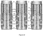
- the smart completion and gradual opening and closing valve illustrated in figures 22.1, 22.2, 22.3, where the drawings indicate the valve positions totally open (22.1), partially open (22.2) and totally closed (22.3).
- the innovative actuator cylinder concept in smart completion valves it was necessary to divide the system into 2 or 4 smaller actuator cylinders positioned laterally to the axis of the production column so that the actuation of these, closing or restricting a zone flow, did not affect the production of the others. It is highlighted that, in a smart completion, the objective is to produce or inject in several zones together with independent control for each interval. Each interval will produce or inject through its respective valve, the flow of which will flow or enter laterally from the annular space into the column where it will mix with the production of the other zones. The amount of teeth in the rack will determine the size of the opening in the actuator cylinder per pressure x depressurization cycle. In this way, it is understood that the opening and closing process is not continuous, but stepped, although such steps can be formed by small increments.
- It is a eleventh object of the present invention to provide a selecting valve of operation fluid comprising a selecting valve body (65) provided with two passages in order to segregate the flow of one primary fluid of the flow of one secondary fluid, being the primary fluid provided with at least a property different from the secondary fluid.
- Oil reservoirs need, at some point in their productive lives, a method to supplement the energy (pressure) of hydrocarbon bearing rocks.
- the preferred artificial lifting methods in the underwater completions and/or high discharge wells are: gas lift and/or BCS.
- Gas lift mandrels are devices with a side pocket, eccentric relative to the center of the production column, where valves will be housed which will allow one-way flow of the annular space (space between the coating and the production column) into the production column.
- these mandrels with their respective valves, are positioned as deeply as possible inside the wells. These valves allow the gas passage being injected into the annular space to gasify the produced fluids, reducing the density of the mixture and allowing the pressure energy of the reservoir rocks to be enough to cause the flow to reach the production facilities.
- the mandrel itself has only holes that, without its respective valve housed in the pocket, would pass in both directions “column x annular". However, with the valve installed, this path is only in the "annular x column" direction.
- the device hereinafter referred to as the selective valve, proposes to be an advantageous alternative to the current gas lift mandrels, allowing liquid and gas flows at the maximum possible flow rates, reducing probe times and providing more effective column cleaning during workovers.
- This device is specially designed to be positioned below BCS assemblies and can be used at any point in the production column.
- the gas lift valve applied in the selective valve of the present invention is provided with two passages being them one primary hole (19) and one secondary hole (20), in order to segregate the flow of one primary fluid of the flow of one secondary fluid, being the primary fluid provided with at least a property different from the secondary fluid, additionally the valve is composed of the following items:
- the distinction property of one primary fluid from one secondary fluid is selected from: compressibility, viscosity, density, pressure or a combination thereof.
- gas lift valve applied in the selective valve (SV) of the present invention positioned below the set of submerged centrifugal pumps (BCS), and the lower end of the flow tube (71) geometrically compatible with the sealing piston head (66).
- actuation means are each one a spring, but not limited to it.
- the secondary actuation mechanism (69) spring comprises elastic constant higher than elastic constant of the primary actuation mechanism spring (67).
- the selective mandrel is composed of the following items:
- EP electro-hydraulic
- It is a fifteenth and last object of the present invention is to provide an exploration method in drilled well using an electro-hydraulic connector and/or electric-hydraulic joint as defined in this description.
- electric connectors (80, 87) have protection mechanism (78, 85).
- protection mechanisms (78, 85) are driven by mechanic elastic device (79, 86).
- hydraulic connectors have sealing (89) in order to ensure complete water-tightness thereof.
- the present invention has also the following advantages: enable the use of smart completions of multiple zones; reduce welding times in workovers for exchanging sets of joint BCS with smart completion; and allow completions with hydraulic valves remotely controlled.
- annular region consists of the region of clearance between the inner wall of the removable capsule and the elevation assembly or the pumping duct, as mounting arrangement.
- the annular region generally comprises the region between the main duct, whereby the well produces fluids, and the coating of the said well.
- All objects of the present invention are intended for the exploration of drilled wells for extraction/elevation of hydrocarbons, of which may be listed: petroleum; gas; bitumen; or any other equivalent, of commercial interest for processing and/or application in several areas of the industry.
- first main tube (MT1) having packer seal bore (11) in its lower portion.
- first inner capsule (IT1) provided with gas lift mandrel (21), isolating valve (28) and primary coupling (29).
- the first inner capsule (IT1) also has an upper polished region (15A) for seating the packer feedthru (3).
- the first lifting assembly (PA1) provided with flapper valve (2), fixation clamp (5), packer feedthru (3), pumping device (4), pressure sensor PDG (8), injection valve (30) and secondary coupling (12).
- PA1 flapper valve (2), fixation clamp (5), packer feedthru (3), pumping device (4), pressure sensor PDG (8), injection valve (30) and secondary coupling (12).
- the primary coupling (29) present in the first inner capsule (IT1) is coupled into the packer seal bore (11) and seals fluids leakage through an elastomeric sealing (31) present in the said primary coupling (29).
- the secondary coupling (12) is responsible for opening the isolating valve (28) present in the first inner capsule (IT1).
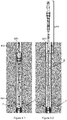
- Figures 4.1 and 4.2 illustrate a sequence of removal of the first lifting assembly (PA1) for wells of a single producing zone (7).
- Figure 4.1 illustrates the first lifting assembly (PA1) inserted into the first inner capsule (IT1) that, in turn, is inserted into the first main tube (MT1).
- the primary coupling (29) present in the first inner capsule (IT1) is inserted into the packer seal bore (11) present in the first main tube (MT1).
- secondary coupling (12) is inserted into the isolating valve (28), in order to keep it opened, allowing fluids production from the drilled well.
- Figure 5 illustrates the complete mount of the lower part of a production column (1) for well with more than one producing zone (7), the known completions of multiple producing zones. It is noted the presence of flapper valve (2) preventing fluids return downstream thereof, fixation clamp (5), and packer feedthru (3) responsible for sealing and seating the second lifting assembly (PA2) inside the second inner capsule (IT).
- the pumping device (4) is located below the packer feedthru (3).
- the locator feedtrhu (6) are responsible for isolating several producing zones that may be met by the present invention.
- the upper locator feedtrhu (6A) separates the first producing zone (7A) from the upper region, where the pumping device (4) is located.
- a pressure sensor PDG (8) and a smart valve (9) are previewed to imply in the well operation, according to external commands, or pre-scheduled. Lower down, its is found the lower locator feddtrhu (6B) segregating a second producing zone (7B) and, then as in the first producing zone (7A), the said second producing zone (7B) has pressure sensor PDG (8) and smart valve (9), besides a handling tool (10). Still in image 5, there is the packer seal bore (11) responsible for housing the secondary coupling (12).
- inner valves (13) present in the first producing zone (7A) and in the second producing zone (7B), such that to allow the produced fluids in the said zones to permeate the inner part of the column through screwed holes (14), also present in both producing zones (7A and 7B).
- Inner valves (13) will be detailed along the description. In this image, it is shown how to apply the knowledge of using a capsule to have the submerged centrifugal pumping assembly in completions of multiple producing zones.
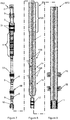
- FIGs 6A and 6B detail mechanisms inside the production column (1) for multiple producing zones, in order to promote a better view thereof.
- figure 6A details the flapper valve (2) preventing the return of the produced fluids and those already pumped downstream thereof, the fixation clamp (5) fixing electric cables and hydraulic lines, among others, the packer feedthru (3) centralizing and fixing the second lifting assembly (PA2) inside the second inner capsule (IT2) and the pumping device (4) supplying energy to the fluid that is being produced from the drilled well, in order to pump it and remove it, being the said pumping device (4) located below the packer feedthru (3).
- PA2 the second lifting assembly
- IT2 second inner capsule
- Figure 6B details the upper locator feddtrhu (6A) separating the first producing zone (7A), where it is also noted a pressure sensor PDG (8) and a smart valve (9) arranged for implying in the well operation, according to external commands, or pre-scheduled.
- a pressure sensor PDG (8) and a smart valve (9) arranged for implying in the well operation, according to external commands, or pre-scheduled.
- the lower locator feddtrhu (6B) segregating a second producing zone (7B) also with pressure sensor PDG (8) and smart valve (9).
- Figure 7 illustrates the second lifting assembly (PA2), which may be easily removed from inside the second inner capsule (IT2), in order to allow the pumping device (4) exchange without the need of onerous workovers.
- Figure 8 discloses the second inner capsule (IT2) with upper polished region (15A) for seating the packer feedthru (3), besides the inner valves (13) allowing the produced fluids passage through screwed holes (14).
- the lower polished regions (15B) are useful for correct seating of the upper and lower locator feddtrhu (6A and 6B).
- the secondary coupling (12) ends the second inner capsule (IT2).
- the said second inner capsule (IT2) is a tube aiming to have the second lifting assembly (PA2), in order to avoid possible parts to loose from the said second lifting assembly (PA2) when removing this.
- image 9 illustrates the second main tube (MT2), which is the coating tube of the production column (1).
- the said second main tube (MT2) is responsible for having screwed holes (14), allowing the produced fluids to pass to the inner part of the production column.
- the same has packer seal bore (11) in its lower part so the well may be closed when it is not with the second inner capsule (IT2) dully positioned.
- Figures 10.1, 10.2 and 10.3 illustrate how inner valves (13) are operated by the handling tool (10).
- Figures 10.1, 10.2 and 10.3 were arranged with a representation in plant (arranged in the lower part of the in lifting views) of the inner part of the handling tool (10) and of the inner valve (13), in each one of the situations depicted.
- the vector (16) indicates the handling tool (10) displacement that, according to figure 10.1 , is in a position where the handling tool (10E) splines are conflicting with the inner valve (13E) splines, being then, the movement (vector 16) imposed by the handling tool (10) is transferred to the inner valve (13), that also starts to displace in the vector direction (16).
- Figure 10.2 depicts this movement in one intermediate instant, also with handling tool (10E) splines displaced from inner valve (13E) splines.
- image 10.3 depicts one instant that, through the handling tool (10) turn, the handling tool splines (10E) are aligned with the inner valve (13E) splines, such that the said handling tool (10) keeps its movement in the vector direction (16), however the inner valve (13), provided with the inner valve splines (13E), keeps stopped.
- image 10.3 it is realized that screwed holes (14) were opened, allowing the fluids to enter from the producing upper zone (7).
- FIG 11 illustrates the pumping device (4), with one electric engine (4A) coupled to a submerged centrifugal pump (4B).
- This set is known by those skilled in the art as set of BCS, or set of submerged centrifugal pump.
- the electro-hydraulic telescopic joint (TJ) of the present invention is composed of: outer liner (32), upper concentric sleeve (33), outer flow tube (34), cables (35), expandable hydraulic unit (36), sliding sleeve (37), inner liner (38), inner flow tube (39), lower concentric sleeve (40) and driving line (41) for driving the mechanical lock (42).
- the mounting of the electro-hydraulic telescopic joint (TJ) is made by associating between outer liner (32) and inner liner (38).
- the upper concentric sleeve (33) has one central hole for associating the outer flow tube (34) and several concentric smaller holes where expandable hydraulic units (36) are associated.
- Expandable hydraulic units (36) are coupled one in another, in order to achieve, when totally open, a length greater than the total course of the electro-hydraulic telescopic joint (TJ) totally open. This makes necessary to avoid efforts transfer being for these units and for outer liners (32) and inner liners (38).
- the cable (35) is mounted in spiral way around the inner flow tube (39). Along the outer flow tube (34) the cable (35) is attached, kept slightly pulled by the sliding sleeve (37).
- the said sliding sleeve (37) when traveling the inner flow tube (39) length, through contraction, or expansion of the electro-hydraulic telescopic joint (TJ), causes the cable (35) spirally arranged around the inner flow tube (39) to be compacted, or extended, without damaging the said cable (35).
- the set composing the named outer liner (32) is formed basically by the expandable hydraulic units (36), outer flow tube (34) and upper concentric sleeve (33).
- the said outer liner (32) is associated to the inner liner (38) by coupling the outer flow tube (34) to the inner flow tube (39) through the sliding sleeve (37).
- the sliding sleeve (37) slides around the inner flow tube (39), promoting the expansion and contraction of the electro-hydraulic telescopic joint (TJ).
- a mechanical lock (42) that, through the driving line (41), allows the relative movement between the sliding sleeve (37) and the inner flow tube (39).
- the mechanical lock (42) is used to lock or not the electro-hydraulic telescopic joint (TJ).
- Figures 13 and 14 illustrate one comparison of drilled wells having production columns (1) and telescopic joint (TJ). Specifically, figure 13 illustrates one well wherein the production column is not equipped with telescopic joint (TJ), and figure 14 illustrates a production column (1) provided with the said telescopic joint (TJ).
- JTEH Electro-Hydraulic Telescopic Joint
- the electro-hydraulic telescopic joint allows the lifting assembly (PA) to be emerged in the surface without the completion remaining is removed.
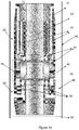
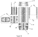
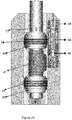
- Figure 15 discloses an embodiment of the shut-off valve (CV), where it is possible to note the linear actuator (43), responsible for opening and closing of the production column and, inversely, of the annular space (AE). Together with linear actuator (43) there is a rack (44) arranged in contact with a gear (45) that, when displaced, provokes the shut-off valve body (46) turn.
- linear actuator 43
- AE annular space
- Gears (45) are constructed with the ratchet system (47), such that the shut-off valve body (46) rotates only in one direction.
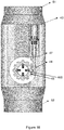
- Figure 16 illustrates a cross side view of the system of gear (45) and rack (44), where it is possible to note the arrangement of the ratchet system (47), this system formed by return elastic elements (48) pressing projections at angle (49) against the gear inner part (45).
- the said gear inner part (45) has cavities (50) for accommodating projections at angle (49).
- the linear actuator (43) and rack (44) operation is apparent.
- Image 17 highlights the linear actuator (43) operation associated to the rack (44) operating the ratchet system (47) formed by the gear (45) having cavities (50), return elastic elements (48) and projections at angle (49).
- an exploded view depicts the shut-off valve (CV) components.
- the linear actuators (43), associated to racks (44), in the ascending or descending direction will result in the gear rotation (45) in the clockwise or counter-clockwise direction.
- projections at angle (49) forced by the return elastic elements (48) against the cavities (50) present in the gears (45) will force the grooved cylindrical shaft (46S) rotation, being the said grooved cylindrical shaft (46S) joint to the shut-off valve body (46), the latter rotates, causing to open or close of the drilled well and, in , causing to open or close the annular space (AE).
- shut-off valve (CV) mount is simple due to the tiny amount of components.
- the lower connection flange (52) mounting is started. This component will be leaked axially by one greater hole (57), where produced fluids will pass and, concentrically, by one or more smaller flange holes (55) where the fluid of completion will pass resulting from the annular space (AE) during reverse circulation operations.
- Such flange holes (55) will be provided from retention valves to allow the flow in single direction of the annular space (AE) to the column.
- valve shell (56) Over the lower connection flange (52), the valve shell (56) is mounted.
- the valve shell (56) has shell holes (57) that, in the valve shell (56) mounting over the lower connection flange (52), they must be aligned with the flange holes (55).
- the shut-off valve body (46) is inserted into the valve shell (56), forming the main mechanism of the shut-off valve (CV).
- shut-off valve body (46) shall also have side holes perpendicular regarding the central hole, where the produced fluids of the drilled well pass through, but without coinciding in order to allow reverse circulations with the production hole closed, preventing the well to absorb fluids.
- the spiral reservoir (53) is mounted with linear actuators (43) and upper connection flange (51), over the cylindrical wrap (54).
- Image 19 depicts ratchet system components (47), which are responsible for causing the shut-off valve body (46) rotation in a single direction.
- ratchet system components 47
- the grooved cylindrical shaft (46S) the gear (45), the set of projections at angle (49) and return elastic elements (48) and, finally, the ratchet system mounting (47).
- Image 20 illustrates, in plant, the main mechanisms of the shut-off valve (CV). It is possible to note the presence of cylindrical wrap (54) having the valve shell (56), the shut-off valve body (46), the linear actuators (43) and gears (45).
- Figures 21.1, 21.2, 21.3 and 22 disclose an embodiment for a system for controlling valve (6) associated to shut-off valve (CV), such that to provide control thereof.
- CV shut-off valve
- Figure 21.1 refers to shut-off valve (CV) during a flow being produced from the drilled well.
- Figure 21.2 illustrates the shut-off valve (CV) during a production stop and, finally, image 21.3 illustrates the shut-off valve (CV) in the well reopening wherein it becomes necessary to pressurize the annular space.
- the control mechanism (CM) is not driven by the inner sleeve (17), since there is a flow being produced and, therefore, keeping the said inner sleeve (17) in an upper position.
- the mechanic actuator (58) is extended and the drainage hole (60) does not allow the fluid to pass through the primary duct (63).
- Such primary duct (63) connects the production main hole to the linear actuator (43), such that the fluid pressure, which is being produced, is the same acting over the linear actuator (43).
- the differential piston (61) does not allow the pressure of the annular space (AE) to be detected by the hydraulic actuator (59), such that the pressure performed over the said hydraulic actuator (59) is the pressure resulting from the primary duct (63), which is in the same pressure of the fluids being produced from the drilled well. It is also previewed an anti-return valve, or one way valve (V) arranged in the communication between the annular space (AE) and the shut-off valve (CV) internal part.
- the first actuation mean (18) displaces the inner sleeve (17) against the mechanic actuator (58), such that this allows the fluid, being produced, pressure to pass towards the hydraulic actuator (59), displacing it to the left.
- the hydraulic actuator (59) connects the upper and lower portions of the primary duct (63), such that linear actuator (43) is displaced in the ascending direction.
- the differential piston (61) is found in the arrangement presented in figure 21.1, since the annular space (AE) was not pressurized, necessary pre-requirement so the said differential piston (61) is displaced. Also in this image, it can highlight that the secondary elastic element (60), associated to the mechanic actuator (58) is compressed.
- FIG. 21.3 illustrates one instant wherein the annular space (AE) was pressurized and displaced the differential piston (61) to the right, what opened the passage for the annular space fluid to fill a secondary duct (64), being the said secondary duct (64) communicating with the left side of the hydraulic actuator (59), such that the said hydraulic actuator (59), under the annular space (AE) pressure displaced to the right, so the drainage hole (60) cuts the communication between the upper and lower part of the primary duct (63).
- This causes the pressure of the annular space (AE), directly connected to the linear actuator (43), to displace the said linear actuator (43), forcing the ratchet system (47) rotation, opening the shut-off valve (CV). Accordingly, the pressure actuation of the annular space (AE) over the said linear actuator (43) was clear.
- the amount of teeth in the rack (44) will determine the opening size in the shut-off valve body (46) by cycle of pressure x depressurization.
- the opening and closing process is not continuous, but stepped, also such stepping may be formed by small increments.
- Figure 22.1 illustrates the shut-off valve (CV) with shut-off valve body (46) controlling only the communication between the annular space (AE) and the duct inside the valve conducting the produced fluids from the drilled well, according to the present invention teachings. More specifically, figure 22.1 discloses a second embodiment of the shut-off valve (CV) in a position allowing the communication between the annular space (AE) and the duct inside the valve.
- Figure 22.2 illustrates one instant wherein, by acting the control fluids in the linear actuator (43), the rack (44) is displaced, inducing the gear (45) to rotate, causing the shut-off valve body (46) to assume an intermediate position.
- FIG. 22.3 illustrates one instant where the shut-off valve body (46) is in the blocking position of the connection between annular space (AE) and the production column internal part.
- the rack (44) displaced the gear (45) that induced the shut-off valve body (46) to rotate.
- shut-off valve (CV) was described using a linear actuator (43) for displacing its moving parts, so those skilled in the art will value this knowledge and will know to apply other rotating options as the hydraulic engines, electric engines, among other examples.
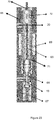
- figure 23 shows an embodiment of the selective valve (SV) of the present invention, having its elements indicated: selecting valve body (65), sealing piston (66) comprising primary actuation mechanism (67), primary hole (19), flow tube (68) comprising secondary actuation mechanism (69), lower end (71) and upper end (72), secondary hole (20) and, finally, the fluid entry (70).
- the said gas will enter into the selective valve (SV) through the fluid entry (70) and the "upstream x downstream" pressure differentials will reach the force of the primary actuation mean (67), causing the sealing piston (2) to lower and the gas to pass inside the production column that fits this completion through primary hole (19), but the viscosity of this first gas will not be able to generate enough friction in the flow tube (68) walls enough to reach the secondary actuation mean (69) force.
- the gas injected in the annular and directed by the selective valve (SV) to the primary hole (19), will enter into the gas-lift mandrel (21) and will gasify the production column, reducing the density of the produced mixture, as currently happens. It is necessary to highlight that the gas, as soon as enter into the production column, remains inside the space formed between upper locator feddtrhu (6A) and lower locator feddtrhu (6B), promoting the proper sealing of the completion fluid, such that the said fluid can enter only into the gas-lift mandrel (21), reducing the density of the produced fluid.
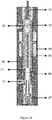
- Figure 24 depicts an embodiment if the completion fluid is liquid, where the Hydrodynamic friction caused in the flow tube (68) walls will be big enough to generate a hydrodynamic drag of the said flow tube (68) downwards, such that this reaches the force of the secondary actuation mean (69) and compressing the "sealing piston" (66) against the upper and lower faces thereof. This promotes the two-way sealing.
- the opening present in the upper end (72) will coincide to the secondary hole (20) and the fluid will enter into the production column through the said secondary hole (20).
- Figure 25 illustrates the selective valve (SV) of the present invention assembled in a completion for wells, where it is possible to note the paths the completion fluid can take after the selective valve (SV).
- the completion fluid When diverting the path inside the gas-lift mandrel (21) and enter by the perforation (73) arranged in the lifting main tube of the completion, the completion fluid does not pass inside the gas-lift mandrel (21), in a way to preserve it, once gas-lift mandrels (21) do not support higher viscosities fluids (water, oil, chemicals, etc.).
- FIGS. 26 to 28 disclose an electro-hydraulic (EP) connector for completion of drilled wells, where electro-hydraulic connectors (EP) allow the disconnection of the production column (1) part for maintenance, according to the present invention teachings.
- EP electro-hydraulic
- FIG 26A there is the external assembly (23) of the electro-hydraulic (EP) connector where it is possible to view the system of stamps (83) that are responsible for displacing the lower electrical contacts protector (78) by compressing the lower spring (79).
- the upper surface (84) is responsible for displacing the upper electrical contacts protector (85) by compressing the upper spring (86).
- the upper spring (86) is extended and the upper electrical contacts protector (85) is positioned in order to provide the correct protection to outer electric connectors (87).
- the electrical connection system also occurs in a modular form, it is enough to add more electrical connection assemblies.
- the threaded element (74) is responsible for interconnecting the internal assembly (22) of the electro-hydraulic (EP) connector to the production column remaining.
- the polished region of the connector (75) is responsible for ensuring the water-tightness of a hydraulic connection (76) operating from one elastomeric elements assembly for connector (77) (these elements are present in the external assembly (23) of the electro-hydraulic (EP) connector) ensuring the complete sealing of the said hydraulic connection (76).
- the several hydraulic connections (76) occur in modular form, being possible to increase the number of connecting points, or reduce them.
- the lower electrical contacts protector (78) are in the extended position through the force action performed by the lower spring (79) in order to ensure proper protection of the internal electric connectors (80).
- the internal tubular region (81) is responsible for supporting well pressures and mechanical stresses of the production column. Between the polished region of the connector (75) and the internal tubular region (81) the region located for allocating hydraulic and electric lines (82) such that the said lines do not experience obstacles occurring inside the internal tubular region (81).
- FIG. 27 it can be seen the electro-hydraulic (EP) connector components when it is in the "connected" position.
- the internal assembly (22) is dully coupled to the external assembly (23) and internal electric connectors (80) and external electric connectors (87) are coupled, besides the hydraulic connection (76) that is also dully connected.
- upper (86) and lower (79) springs are compressed, internal and external electric connectors (80 and 87) are aligned and dully connected and also hydraulic connectors (76) are dully positioned in the polished region (75) in order to ensure total water-tightness of the hydraulic lines.
- FIGS. 28.1 and 28.2 depict a sequence of removal of pumping device (4) by disconnecting the electro-hydraulic (EP) connector, according to the present invention.
- FIG 28.1 it can be noted the accessories of a lower completion (88), generically represented.
- the pumping device (4) generally formed by the engine and pump assembly are represented in a merely illustrative manner and they are connected to the lower completion (88) remainder through electro-hydraulic (EP) connector of the present invention.
- EP electro-hydraulic
- FIG 28.2 illustrates a smart completion provided with electro-hydraulic (EP) connector, with the difference of being in the disconnected position.
- EP electro-hydraulic
- FIG. 28.2 illustrates a smart completion provided with electro-hydraulic (EP) connector, with the difference of being in the disconnected position.
- the present invention will facilitate the decoupling between the upper part having the pumping device (4) and lower completion (88), for maintenance of the said pumping device (4), formed by a BCS, for example.
- the external assembly (23) of the electro-hydraulic (EP) connector is associated to the upper part that was removed from the smart completion and the internal assembly (22) is associated to lower completion (88) of the said smart completion.
- FIG. 29 discloses a second embodiment for electro-hydraulic telescopic joint (TJ) of the present invention. As illustrated, this tool is composed of the following elements:
- Tubular lower component with the following characteristics: outer thread (27) for connecting into electro-hydraulic (EP) connector, sealing (89) in the upper part between the outer tube (24) and the inner tube (25), hexagonal lock system (26) to avoid the inner column to rotate in false, performing torque transmission between the lower and upper component, secondary lock system (90) for column decline with the extension fixed totally in the closed position, external ring upper (91) and external ring lower (92) for aligning external hydraulic and electric lines, filling bars (93) of empty space between the external hydraulic and electric lines and, protection liner (94) of the internal hydraulic and electric lines.
- Tubular upper component with the following characteristics: cylindrical top (95) with thread in the center to the inner tube (25); thread for connecting into the production column (96) and peripheral threads (97) for connecting hydraulic and electric lines.
- the components comprise the electro-hydraulic telescopic joint (TJ) of the figure 29 are dully described below.
- the inner tube (25) refers to a conventional expansion joint.
- the inner tube (25) is composed of one conventional polished cylinder sliding upwards and downwards, with sealing in the outer liner top.
- the defined sliding course for balance will depend on the constructive characteristics, but it can reach up to 6 meters.
- the hexagonal lock (26) in the lower end of the inner cylinder (25) avoids the independent rotation, impairing torque.
- the protection liner (94) is responsible for connecting in the lower part of the column.
- the sealing (89) system with the inner cylinder (25) is located on the top. Internally, the protection liner (94) is machined with shape to keep the cylinder alone in case of rotation.
- the outer body is machined with grooves to partially house the conduction hydraulic and electric lines.
- the protection liner (94) refers to a cylinder coating the outer lines, mechanically protecting against impacts on the lines and keeping the lines positioned so they do not remain out of the position.
- Hydraulic lines are miniatures of the main expansion joint, with one outer tube and one inner tube. The outer fixed and the inner sliding, with sealing of the outer tube top.
- the electric lines are similar to hydraulic lines, but with electric conduction purpose.
Landscapes
- Engineering & Computer Science (AREA)
- Mining & Mineral Resources (AREA)
- Geology (AREA)
- Life Sciences & Earth Sciences (AREA)
- Physics & Mathematics (AREA)
- General Life Sciences & Earth Sciences (AREA)
- Fluid Mechanics (AREA)
- Environmental & Geological Engineering (AREA)
- Geochemistry & Mineralogy (AREA)
- General Engineering & Computer Science (AREA)
- Mechanical Engineering (AREA)
- Geophysics (AREA)
- Earth Drilling (AREA)
- Fluid-Pressure Circuits (AREA)
- Safety Valves (AREA)
- Quick-Acting Or Multi-Walled Pipe Joints (AREA)
Applications Claiming Priority (9)
| Application Number | Priority Date | Filing Date | Title |
|---|---|---|---|
| BR102014024581A BR102014024581A2 (pt) | 2014-10-01 | 2014-10-01 | sistema e método para extração de petróleo e cápsula de revestimento |
| BR102014024580A BR102014024580A2 (pt) | 2014-10-01 | 2014-10-01 | sistema e método para extração de petróleo |
| BR102014024851A BR102014024851A2 (pt) | 2014-10-03 | 2014-10-03 | válvula de gás lift aplicada em mandril, mandril de gás lift seletivo e sistema de elevação por gás lift |
| BR102014024858A BR102014024858A2 (pt) | 2014-10-03 | 2014-10-03 | junta telescópica e processo de extração de petróleo |
| BR102014024854A BR102014024854A2 (pt) | 2014-10-03 | 2014-10-03 | válvula e método para fechamento e isolamento de formações produtoras de hidrocarbonetos |
| BR102014029576A BR102014029576A2 (pt) | 2014-11-14 | 2014-11-14 | vávula de fechamento de fundo e válvula de complementação inteligente |
| BR102014028656A BR102014028656A2 (pt) | 2014-11-17 | 2014-11-17 | sistema de completação inteligente e processo de extração de petróleo |
| BR102015002643A BR102015002643A2 (pt) | 2015-02-06 | 2015-02-06 | conector eletro-hidráulico, junta de expansão eletro-hidráulica e processo de extração de petróleo utilizando os mesmos |
| PCT/BR2015/050166 WO2016049726A1 (fr) | 2014-10-01 | 2015-10-01 | Système et procédé de complétion, procédé d'exploration de puits de forage, utilisation de ceux-ci dans l'exploration/extraction de puits de forage, capsule de conditionnement, joint télescopique, vanne et procédé d'isolation et système d'actionnement de celle-ci, vanne sélectrice et son utilisation, et raccord et joint de dilatation électro-hydraulique |
Publications (2)
| Publication Number | Publication Date |
|---|---|
| EP3203014A1 true EP3203014A1 (fr) | 2017-08-09 |
| EP3203014A4 EP3203014A4 (fr) | 2018-10-17 |
Family
ID=55629183
Family Applications (1)
| Application Number | Title | Priority Date | Filing Date |
|---|---|---|---|
| EP15846958.5A Withdrawn EP3203014A4 (fr) | 2014-10-01 | 2015-10-01 | Système et procédé de complétion, procédé d'exploration de puits de forage, utilisation de ceux-ci dans l'exploration/extraction de puits de forage, capsule de conditionnement, joint télescopique, vanne et procédé d'isolation et système d'actionnement de celle-ci, vanne sélectrice et son utilisation, et raccord et joint de dilatation électro-hydraulique |
Country Status (5)
| Country | Link |
|---|---|
| US (1) | US20170292326A1 (fr) |
| EP (1) | EP3203014A4 (fr) |
| BR (1) | BR112017006454A2 (fr) |
| MX (1) | MX2017004315A (fr) |
| WO (1) | WO2016049726A1 (fr) |
Cited By (1)
| Publication number | Priority date | Publication date | Assignee | Title |
|---|---|---|---|---|
| CN110847859A (zh) * | 2019-11-11 | 2020-02-28 | 中国海洋石油集团有限公司 | 一种智能完井井下流量阀地面控制超高压液压系统 |
Families Citing this family (11)
| Publication number | Priority date | Publication date | Assignee | Title |
|---|---|---|---|---|
| MX2021008206A (es) | 2020-07-07 | 2022-01-10 | Petroleo Brasileiro Sa Petrobras | Sistema y metodo para terminacion electrica inteligente en depositos que permiten la terminacion de pozo abierto. |
| WO2022103956A1 (fr) | 2020-11-11 | 2022-05-19 | Baker Hughes Oilfield Operations Llc | Mandrin à poches latérales d'ascension par poussée de gaz avec poches interchangeables modulaires |
| US11933150B2 (en) | 2021-01-14 | 2024-03-19 | Baker Hughes Oilfield | Electric remote operated gas lift mandrel |
| US11542798B2 (en) | 2021-02-08 | 2023-01-03 | Baker Hughes Oilfield Operations Llc | Variable orifice valve for gas lift mandrel |
| US11692405B2 (en) | 2021-02-10 | 2023-07-04 | Baker Hughes Oilfield Operations Llc | Guide sleeve for use with side pocket mandrel |
| AU2022359895B2 (en) | 2021-10-06 | 2024-05-09 | Baker Hughes Oilfield Operations Llc | Dual string gas injection system with flow control |
| AU2023383160A1 (en) | 2022-11-14 | 2025-06-05 | Baker Hughes Oilfield Operations Llc | Side pocket mandrel with direct check valves |
| US12276192B2 (en) | 2022-12-27 | 2025-04-15 | Petróleo Brasileiro S.A.—Petrobras | System and method for construction and completion of production and injection wells in the pre-salt fields |
| US12297723B2 (en) | 2023-04-19 | 2025-05-13 | Baker Hughes Oilfield Operations Llc | Electric closing side pocket mandrel |
| US12398629B2 (en) | 2023-04-19 | 2025-08-26 | Baker Hughes Oilfield Operations Llc | Side pocket mandrel with retrievable redundant electric gas lift valve |
| US12492618B2 (en) | 2023-10-05 | 2025-12-09 | Baker Hughes Oilfield Operations Llc | Delayed opening side pocket mandrel |
Family Cites Families (15)
| Publication number | Priority date | Publication date | Assignee | Title |
|---|---|---|---|---|
| US4350205A (en) * | 1979-03-09 | 1982-09-21 | Schlumberger Technology Corporation | Work over methods and apparatus |
| US6179056B1 (en) * | 1998-02-04 | 2001-01-30 | Ypf International, Ltd. | Artificial lift, concentric tubing production system for wells and method of using same |
| US6873267B1 (en) * | 1999-09-29 | 2005-03-29 | Weatherford/Lamb, Inc. | Methods and apparatus for monitoring and controlling oil and gas production wells from a remote location |
| US6412563B1 (en) * | 2000-04-21 | 2002-07-02 | Baker Hughes Incorporated | System and method for enhanced conditioning of well fluids circulating in and around artificial lift assemblies |
| US6568475B1 (en) * | 2000-06-30 | 2003-05-27 | Weatherford/Lamb, Inc. | Isolation container for a downhole electric pump |
| US7051815B2 (en) * | 2002-08-22 | 2006-05-30 | Baker Hughes Incorporated | Well pump capsule |
| AU2004225541B2 (en) * | 2003-03-28 | 2008-03-13 | Shell Internationale Research Maatschappij B.V. | Surface flow controlled valve and screen |
| US7150325B2 (en) * | 2003-07-25 | 2006-12-19 | Baker Hughes Incorporated | ROV retrievable sea floor pump |
| US7736133B2 (en) * | 2006-05-23 | 2010-06-15 | Baker Hughes Incorporated | Capsule for two downhole pump modules |
| US7900705B2 (en) * | 2007-03-13 | 2011-03-08 | Schlumberger Technology Corporation | Flow control assembly having a fixed flow control device and an adjustable flow control device |
| US8127845B2 (en) * | 2007-12-19 | 2012-03-06 | Schlumberger Technology Corporation | Methods and systems for completing multi-zone openhole formations |
| BRPI0910644A2 (pt) * | 2008-04-15 | 2015-09-22 | Cameron Int Corp | sistema de completação de árvore de multisseções |
| US8740586B2 (en) * | 2009-06-29 | 2014-06-03 | Baker Hughes Incorporated | Heat exchanger for ESP motor |
| US8651188B2 (en) * | 2009-12-30 | 2014-02-18 | Schlumberger Technology Corporation | Gas lift barrier valve |
| US8893783B2 (en) * | 2012-09-26 | 2014-11-25 | Halliburton Energy Services, Inc. | Tubing conveyed multiple zone integrated intelligent well completion |
-
2015
- 2015-10-01 BR BR112017006454A patent/BR112017006454A2/pt not_active IP Right Cessation
- 2015-10-01 EP EP15846958.5A patent/EP3203014A4/fr not_active Withdrawn
- 2015-10-01 WO PCT/BR2015/050166 patent/WO2016049726A1/fr not_active Ceased
- 2015-10-01 US US15/516,199 patent/US20170292326A1/en not_active Abandoned
- 2015-10-01 MX MX2017004315A patent/MX2017004315A/es unknown
Cited By (1)
| Publication number | Priority date | Publication date | Assignee | Title |
|---|---|---|---|---|
| CN110847859A (zh) * | 2019-11-11 | 2020-02-28 | 中国海洋石油集团有限公司 | 一种智能完井井下流量阀地面控制超高压液压系统 |
Also Published As
| Publication number | Publication date |
|---|---|
| WO2016049726A1 (fr) | 2016-04-07 |
| US20170292326A1 (en) | 2017-10-12 |
| BR112017006454A2 (pt) | 2017-12-12 |
| EP3203014A4 (fr) | 2018-10-17 |
| MX2017004315A (es) | 2018-01-17 |
Similar Documents
| Publication | Publication Date | Title |
|---|---|---|
| EP3203014A1 (fr) | Système et procédé de complétion, procédé d'exploration de puits de forage, utilisation de ceux-ci dans l'exploration/extraction de puits de forage, capsule de conditionnement, joint télescopique, vanne et procédé d'isolation et système d'actionnement de celle-ci, vanne sélectrice et son utilisation, et raccord et joint de dilatation électro-hydraulique | |
| EP1270870B1 (fr) | Appareil pour tester un obturateur anti-éruption | |
| CA2531364C (fr) | Procede de deploiement et d'alimentation d'un dispositif entraine electriquement dans un puits | |
| US3411576A (en) | Well tools | |
| US9051811B2 (en) | Barrier valve system and method of controlling same with tubing pressure | |
| DE60003180T2 (de) | Verfahren zum anbringen einer elektrischen fördereinrichtung im bohrloch | |
| US8689879B2 (en) | Fluid displacement methods and apparatus for hydrocarbons in subsea production tubing | |
| RU2107806C1 (ru) | Трубный испытательный клапан и способ извлечения испытательной колонны из постоянного пакера | |
| US9695665B2 (en) | Subsea chemical injection system | |
| US10066458B2 (en) | Intervention system and apparatus | |
| US20170191324A1 (en) | Hanger, hanger tool, and method of hanger installation | |
| NO323369B1 (no) | Apparat for a kople et nedsenkbart pumpesystem til et utplasseringssystem. | |
| US11913300B1 (en) | Wellbore chemical injection with tubing spool side extension flange | |
| US11035198B2 (en) | Multifunction blowout preventer | |
| US20150267504A1 (en) | Cement pulsation for subsea wellbore | |
| EP3262275B1 (fr) | Système et procédé d'accès à un puits | |
| WO2019083352A1 (fr) | Procédé et système d'installation d'une pompe submersible électrique | |
| US11236592B2 (en) | Valve system | |
| AU2014382687A1 (en) | Expansion cone for downhole tool | |
| RU2289012C2 (ru) | Разъединитель-соединитель шарифова для пакерной установки скважины (варианты) | |
| RU2049223C1 (ru) | Пакер | |
| US10590727B1 (en) | Hanger system | |
| US12221854B2 (en) | Wellbore chemical injection with tubing spool side extension flange | |
| CA3065191C (fr) | Systeme de vanne |
Legal Events
| Date | Code | Title | Description |
|---|---|---|---|
| PUAI | Public reference made under article 153(3) epc to a published international application that has entered the european phase |
Free format text: ORIGINAL CODE: 0009012 |
|
| 17P | Request for examination filed |
Effective date: 20170427 |
|
| AK | Designated contracting states |
Kind code of ref document: A1 Designated state(s): AL AT BE BG CH CY CZ DE DK EE ES FI FR GB GR HR HU IE IS IT LI LT LU LV MC MK MT NL NO PL PT RO RS SE SI SK SM TR |
|
| AX | Request for extension of the european patent |
Extension state: BA ME |
|
| DAV | Request for validation of the european patent (deleted) | ||
| DAX | Request for extension of the european patent (deleted) | ||
| RIC1 | Information provided on ipc code assigned before grant |
Ipc: F16K 31/12 20060101ALI20180430BHEP Ipc: E21B 34/10 20060101ALI20180430BHEP Ipc: E21B 43/10 20060101ALI20180430BHEP Ipc: F04D 13/08 20060101ALI20180430BHEP Ipc: E21B 43/12 20060101AFI20180430BHEP Ipc: E21B 43/14 20060101ALI20180430BHEP Ipc: E21B 41/00 20060101ALI20180430BHEP Ipc: F16L 27/00 20060101ALI20180430BHEP Ipc: F16K 15/00 20060101ALI20180430BHEP Ipc: E21B 33/035 20060101ALI20180430BHEP |
|
| A4 | Supplementary search report drawn up and despatched |
Effective date: 20180919 |
|
| RIC1 | Information provided on ipc code assigned before grant |
Ipc: F04D 13/06 20060101ALI20180913BHEP Ipc: E21B 43/14 20060101ALI20180913BHEP Ipc: E21B 41/00 20060101ALI20180913BHEP Ipc: E21B 34/10 20060101ALI20180913BHEP Ipc: F16K 31/12 20060101ALI20180913BHEP Ipc: F04D 13/08 20060101ALI20180913BHEP Ipc: E21B 43/12 20060101AFI20180913BHEP Ipc: F16L 27/00 20060101ALI20180913BHEP Ipc: E21B 43/10 20060101ALI20180913BHEP Ipc: F16K 15/00 20060101ALI20180913BHEP Ipc: F04D 13/10 20060101ALI20180913BHEP Ipc: E21B 33/035 20060101ALI20180913BHEP |
|
| STAA | Information on the status of an ep patent application or granted ep patent |
Free format text: STATUS: THE APPLICATION HAS BEEN WITHDRAWN |
|
| 18W | Application withdrawn |
Effective date: 20190325 |