EP3203016A1 - Spaltkontrolle in einem gasturbinentriebwerk mittels schubausgleichskanälen - Google Patents
Spaltkontrolle in einem gasturbinentriebwerk mittels schubausgleichskanälen Download PDFInfo
- Publication number
- EP3203016A1 EP3203016A1 EP17153504.0A EP17153504A EP3203016A1 EP 3203016 A1 EP3203016 A1 EP 3203016A1 EP 17153504 A EP17153504 A EP 17153504A EP 3203016 A1 EP3203016 A1 EP 3203016A1
- Authority
- EP
- European Patent Office
- Prior art keywords
- gas turbine
- turbine engine
- component
- rotating component
- axially
- Prior art date
- Legal status (The legal status is an assumption and is not a legal conclusion. Google has not performed a legal analysis and makes no representation as to the accuracy of the status listed.)
- Granted
Links
Images




Classifications
-
- F—MECHANICAL ENGINEERING; LIGHTING; HEATING; WEAPONS; BLASTING
- F01—MACHINES OR ENGINES IN GENERAL; ENGINE PLANTS IN GENERAL; STEAM ENGINES
- F01D—NON-POSITIVE DISPLACEMENT MACHINES OR ENGINES, e.g. STEAM TURBINES
- F01D11/00—Preventing or minimising internal leakage of working-fluid, e.g. between stages
- F01D11/08—Preventing or minimising internal leakage of working-fluid, e.g. between stages for sealing space between rotor blade tips and stator
- F01D11/14—Adjusting or regulating tip-clearance, i.e. distance between rotor-blade tips and stator casing
- F01D11/20—Actively adjusting tip-clearance
- F01D11/22—Actively adjusting tip-clearance by mechanically actuating the stator or rotor components, e.g. moving shroud sections relative to the rotor
-
- F—MECHANICAL ENGINEERING; LIGHTING; HEATING; WEAPONS; BLASTING
- F01—MACHINES OR ENGINES IN GENERAL; ENGINE PLANTS IN GENERAL; STEAM ENGINES
- F01D—NON-POSITIVE DISPLACEMENT MACHINES OR ENGINES, e.g. STEAM TURBINES
- F01D25/00—Component parts, details, or accessories, not provided for in, or of interest apart from, other groups
- F01D25/24—Casings; Casing parts, e.g. diaphragms, casing fastenings
-
- F—MECHANICAL ENGINEERING; LIGHTING; HEATING; WEAPONS; BLASTING
- F01—MACHINES OR ENGINES IN GENERAL; ENGINE PLANTS IN GENERAL; STEAM ENGINES
- F01D—NON-POSITIVE DISPLACEMENT MACHINES OR ENGINES, e.g. STEAM TURBINES
- F01D3/00—Machines or engines with axial-thrust balancing effected by working-fluid
- F01D3/04—Machines or engines with axial-thrust balancing effected by working-fluid axial thrust being compensated by thrust-balancing dummy piston or the like
-
- F—MECHANICAL ENGINEERING; LIGHTING; HEATING; WEAPONS; BLASTING
- F01—MACHINES OR ENGINES IN GENERAL; ENGINE PLANTS IN GENERAL; STEAM ENGINES
- F01D—NON-POSITIVE DISPLACEMENT MACHINES OR ENGINES, e.g. STEAM TURBINES
- F01D5/00—Blades; Blade-carrying members; Heating, heat-insulating, cooling or antivibration means on the blades or the members
- F01D5/12—Blades
-
- F—MECHANICAL ENGINEERING; LIGHTING; HEATING; WEAPONS; BLASTING
- F04—POSITIVE - DISPLACEMENT MACHINES FOR LIQUIDS; PUMPS FOR LIQUIDS OR ELASTIC FLUIDS
- F04D—NON-POSITIVE-DISPLACEMENT PUMPS
- F04D29/00—Details, component parts, or accessories
- F04D29/05—Shafts or bearings, or assemblies thereof, specially adapted for elastic fluid pumps
- F04D29/052—Axially shiftable rotors
-
- F—MECHANICAL ENGINEERING; LIGHTING; HEATING; WEAPONS; BLASTING
- F04—POSITIVE - DISPLACEMENT MACHINES FOR LIQUIDS; PUMPS FOR LIQUIDS OR ELASTIC FLUIDS
- F04D—NON-POSITIVE-DISPLACEMENT PUMPS
- F04D29/00—Details, component parts, or accessories
- F04D29/08—Sealings
- F04D29/16—Sealings between pressure and suction sides
- F04D29/161—Sealings between pressure and suction sides especially adapted for elastic fluid pumps
- F04D29/164—Sealings between pressure and suction sides especially adapted for elastic fluid pumps of an axial flow wheel
-
- F—MECHANICAL ENGINEERING; LIGHTING; HEATING; WEAPONS; BLASTING
- F04—POSITIVE - DISPLACEMENT MACHINES FOR LIQUIDS; PUMPS FOR LIQUIDS OR ELASTIC FLUIDS
- F04D—NON-POSITIVE-DISPLACEMENT PUMPS
- F04D29/00—Details, component parts, or accessories
- F04D29/26—Rotors specially for elastic fluids
- F04D29/32—Rotors specially for elastic fluids for axial flow pumps
- F04D29/321—Rotors specially for elastic fluids for axial flow pumps for axial flow compressors
-
- F—MECHANICAL ENGINEERING; LIGHTING; HEATING; WEAPONS; BLASTING
- F04—POSITIVE - DISPLACEMENT MACHINES FOR LIQUIDS; PUMPS FOR LIQUIDS OR ELASTIC FLUIDS
- F04D—NON-POSITIVE-DISPLACEMENT PUMPS
- F04D29/00—Details, component parts, or accessories
- F04D29/40—Casings; Connections of working fluid
- F04D29/52—Casings; Connections of working fluid for axial pumps
- F04D29/522—Casings; Connections of working fluid for axial pumps especially adapted for elastic fluid pumps
- F04D29/526—Details of the casing section radially opposing blade tips
-
- F—MECHANICAL ENGINEERING; LIGHTING; HEATING; WEAPONS; BLASTING
- F05—INDEXING SCHEMES RELATING TO ENGINES OR PUMPS IN VARIOUS SUBCLASSES OF CLASSES F01-F04
- F05D—INDEXING SCHEME FOR ASPECTS RELATING TO NON-POSITIVE-DISPLACEMENT MACHINES OR ENGINES, GAS-TURBINES OR JET-PROPULSION PLANTS
- F05D2220/00—Application
- F05D2220/30—Application in turbines
- F05D2220/32—Application in turbines in gas turbines
-
- F—MECHANICAL ENGINEERING; LIGHTING; HEATING; WEAPONS; BLASTING
- F05—INDEXING SCHEMES RELATING TO ENGINES OR PUMPS IN VARIOUS SUBCLASSES OF CLASSES F01-F04
- F05D—INDEXING SCHEME FOR ASPECTS RELATING TO NON-POSITIVE-DISPLACEMENT MACHINES OR ENGINES, GAS-TURBINES OR JET-PROPULSION PLANTS
- F05D2240/00—Components
- F05D2240/50—Bearings
- F05D2240/52—Axial thrust bearings
-
- F—MECHANICAL ENGINEERING; LIGHTING; HEATING; WEAPONS; BLASTING
- F05—INDEXING SCHEMES RELATING TO ENGINES OR PUMPS IN VARIOUS SUBCLASSES OF CLASSES F01-F04
- F05D—INDEXING SCHEME FOR ASPECTS RELATING TO NON-POSITIVE-DISPLACEMENT MACHINES OR ENGINES, GAS-TURBINES OR JET-PROPULSION PLANTS
- F05D2260/00—Function
- F05D2260/30—Retaining components in desired mutual position
Definitions
- the subject matter disclosed herein generally relates to clearance control between rotating and static components of a gas turbine engine and, more particularly, to thrust balance manipulation for clearance control.
- Gas turbine engines such as those used to power modem commercial and military aircrafts, generally include a compressor section to pressurize an airflow, a combustor section for burning hydrocarbon fuel in the presence of the pressurized air, and a turbine section to extract energy from the resultant combustion gases.
- the airflow flows along a gas path between components through the gas turbine engine.
- a gas turbine engine includes a plurality of rotating components arranged along an axis of rotation of the gas turbine engine, in both the compressor section and the turbine section.
- the gas turbine engine also includes a number of static components.
- the rotating and static components of the gas turbine engine are made from many different materials and vary in size, thickness, and dimensions. Therefore, each component has a growth pattern that includes thermally and mechanically expanding and contracting at different rates. Such component growth during operation, if left unaccounted for, could cause rotating components of the gas turbine engine to undesirably come into contact with static components causing damage to the gas turbine engine.
- a gas turbine engine with clearance control includes a static component, and a rotating component that shifts axially in one of an aft direction and a forward direction in relation to the static component during a first operating condition of the gas turbine engine, and shifts axially in the other of the aft direction and the forward direction in relation to the static component during a second operating condition of the gas turbine engine.
- the first operating condition is when a rotating component growth and a static component growth change at different rates.
- the second operating condition is when the rotating component growth and static component growth normalize.
- further embodiments of the gas turbine engine may include wherein the rotating component increases a clearance distance between the rotating component and the static component by shifting axially in the first operating condition, and wherein the rotating component decreases the clearance distance between the rotating component and the static component by shifting axially in the second operating condition.
- further embodiments of the gas turbine engine may include wherein a backward most position in the aft direction and a forward most position in the forward direction have a maximum separation distance defined by a thrust bearing freeplay distance.
- further embodiments of the gas turbine engine may include wherein the static component growth and the rotating component growth each include a mechanical expansion value and a thermal expansion value.
- further embodiments of the gas turbine engine may include a compressor that manipulates thrust balance within the compressor that shifts the rotating component axially.
- further embodiments of the gas turbine engine may include thrust balance vents that vent certain parts of the compressor, wherein venting generates axial force within the compressor that shifts the rotating component axially.
- further embodiments of the gas turbine engine may include wherein the compressor includes a plurality of rotating disks with a chamber between each of the plurality of rotating disks, and wherein the chamber on a forward side of each rotating disk has a lower pressure than the chamber on an aft side of each rotating disk that has a higher pressure.
- further embodiments of the gas turbine engine may include a higher pressure chamber that axially shifts the rotating component in the aft direction when the higher pressure chamber is vented, and a lower pressure chamber that axially shifts the rotating component in the forward direction when the lower pressure chamber is vented.
- gas turbine engine may include a gas turbine engine controller that generates a clearance control signal based on operating conditions of the gas turbine engine, wherein the control signal controls axial shifts of the rotating component.
- a system in a gas turbine engine for clearance control includes a gas turbine engine controller that generates a clearance control signal based on operating conditions of the gas turbine engine, wherein the control signal controls axial shifts within the system, a static component, and a rotating component that shifts axially in one of an aft direction and a forward direction in relation to the static component during a first operating condition of the gas turbine engine in response to receiving the clearance control signal, and shifts axially in the other of the aft direction and the forward direction in relation to the static component during a second operating condition of the gas turbine engine in response to receiving the clearance control signal.
- the first operating condition is when a rotating component growth and a static component growth change at different rates.
- the second operating condition is when the rotating component growth and static component growth normalize.
- a method for clearance control between a rotating component and a static component of a gas turbine engine includes shifting the rotating component axially in one of an aft direction and a forward direction in relation to the static component during a first operating condition of the gas turbine engine, wherein the first operating condition is when a rotating component growth and a static component growth change at different rates, determining that the first operating condition has ended and that the gas turbine engine is operating in a second operating condition during which the rotating component growth and static component growth normalize, and shifting the rotating component axially in the other of the aft direction and the forward direction in relation to the static component during the second operating condition.
- further embodiments of the method may include wherein shifting the rotating component axially in the aft direction includes increasing a clearance distance between the rotating component and the static component, and wherein shifting the rotating component axially in the forward direction includes decreasing the clearance distance between the rotating component and the static component.
- further embodiments of the method may include maintaining the clearance distance within a max threshold value and a minimum threshold value.
- further embodiments of the method may include wherein a backward most position in the aft direction and a forward most position in the forward direction have a maximum separation distance defined by a thrust bearing freeplay distance.
- further embodiments of the method may include wherein the rotating component includes a high spool that includes a compressor and a turbine.
- further embodiments of the method may include wherein the static component growth and the rotating component growth each include a mechanical expansion value and a thermal expansion value.
- further embodiments of the method may include wherein shifting the rotating component axially includes manipulating thrust balance in a compressor of the gas turbine engine.
- manipulating the thrust balance includes venting certain parts of the compressor using thrust balance vents, wherein venting generates axial force within the compressor that shifts the rotating component axially.
- further embodiments of the method may include wherein the compressor includes a plurality of rotating disks with a chamber between each of the plurality of rotating disks, wherein a lower pressure is provided in the chamber on a forward side of each rotating disk and a higher pressure is provided in the chamber on an aft side of each rotating disk.
- further embodiments of the method may include venting a higher pressure chamber by axially shifting the rotating component in the aft direction.
- further embodiments of the method may include venting a lower pressure chamber by axially shifting the rotating component in the forward direction.
- Embodiments described herein are directed to a method and system for clearance control between a rotating component and a static component of a gas turbine engine.
- mechanical growth of components can occur in orders of magnitude faster than thermal growth.
- a system as disclosed herein utilizes a sloped flow path and a thrust balance valve that allows additional clearance during initial transient periods and clearance adjustments once thermals and mechanical growth values normalize.
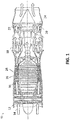
- FIG. 1 a schematic cross-sectional view of a gas turbine engine is shown in accordance with one or more exemplary embodiments.
- FIG. 1 is a schematic illustration of a gas turbine engine 10.
- the gas turbine engine generally has a fan 12 through which ambient air is propelled in the direction of arrow 14, a compressor 16 for pressurizing the air received from the fan 12 and a combustor 18 wherein the compressed air is mixed with fuel and ignited for generating combustion gases.
- the gas turbine engine 10 further includes a turbine section 20 for extracting energy from the combustion gases. Fuel is injected into the combustor 18 of the gas turbine engine 10 for mixing with the compressed air from the compressor 16 and ignition of the resultant mixture.
- the fan 12, compressor 16, combustor 18, and turbine 20 are typically all concentric about a common central longitudinal axis of the gas turbine engine 10.
- the turbine 20 includes one or more turbine stators 22 and one or more turbine rotors 24.
- the compressor 16 includes one or more compressor rotors 26 and one or more compressor stators 28. It is to be appreciated that while the description below relates to compressors 16 and compressor rotors 26, one skilled in the art will readily appreciate that the present disclosure may be utilized with respect to turbine rotors 24.
- different elements of the gas turbine engine can expand and contract due to, for example, rotational mechanical forces and thermal expansion. Further, the elements of the gas turbine engine will expand and contract at different rates and can also expand toward each other. To prevent the different components from coming into contact with each other the clearance distance between the rotating and static components is adjusted by moving the rotating component axially in either the forward or aft direction.
- FIG. 2A illustrates a schematic cross-sectional view of a rotating component 233 and portions of a static component of a gas turbine engine 200 in accordance with one or more exemplary embodiments.
- the rotating component includes a thrust bearing 202, a compressor 203, and a turbine 206.
- the compressor 203 has a forward end 203.1 and an aft end 203.2.
- the portions of the static component that are shown include the bearing portion 201, thrust balance vents 204, and a static wall 205.
- the compressor 203 includes chambers between discs that the thrust balance vents 204 can selectively vent.
- FIG. 2B illustrates a schematic cross-sectional view of a portion of the rotating component 206 and a portion of the static component 205, from indicator box 250 of FIG. 2A , of a gas turbine engine 200 in accordance with one or more exemplary embodiments.
- the static wall 205 which is the portion of the static component 205, can expand as shown a distance 270 outward and toward the rotating component 206.
- the rotating component 206 which may be a turbine 206, can expand outward a distance 260.
- both components expand during a transient period the components could come in contact as shown at point 280. This contact is undesirable.
- the original clearance 207 can be reduced due to the growth of either component 205, 206.
- the components are shifted to create a change in the clearance distance 207.
- FIG. 3A illustrates a schematic cross-sectional view of a portion 302 of a bearing assembly of the rotating component axially shifting in an aft direction and the static component 301 in accordance with one or more exemplary embodiments.
- a bearing assembly is shifted from a forward loaded position 302.1 to an aft position 302.2. This is provided because of the built-in bearing freeplay within the bearing assembly that provided an axial distance along which the bearing assembly can travel.
- the other components of the rotating component also shift the same distance.
- FIG. 3B illustrates a schematic cross-sectional view of a portion of the rotating component axially shifting in an aft direction in accordance with one or more exemplary embodiments.
- the rotating portion is axially shifted in the aft direction in a similar manner to that shown in FIG. 3A .
- the rotating component moves from a forward position 306.1 to an aft position 306.2.
- the static component 305 remains in its original position.
- a clearance distance 307 increases between the components when the rotating component shifts from the forward position 306.1 to the aft position 306.2 during a transient period when growth values of the components are expanding and contracting.
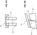
- FIG. 4A illustrates a schematic cross-sectional view of a portion of a bearing assembly of the rotating component axially shifting in a forward direction in accordance with one or more exemplary embodiments. Specifically, as shown, a bearing assembly is shifted from an aft position 402.2 to a forward loaded position 402.1. This is provided because of the built-in bearing freeplay within the bearing assembly that provided an axial distance along which the bearing assembly can travel. In response to this axial shift, the other components of the rotating component also shift the same distance.
- FIG. 4B illustrates a schematic cross-sectional view of a portion of the rotating component axially shifting in a forward direction in accordance with one or more exemplary embodiments.
- the rotating portion is axially shifted in the forward direction in a similar manner to that shown in FIG. 4A .
- the rotating component moves from an aft position 406.2 to a forward position 406.1.
- the static component 405 remains in its original position.
- a clearance distance 407 decreases between the components when the rotating component shifts from the aft position 406.2 to the forward position 406.1 during a growth normalized period of operation.
- FIG. 5 illustrates a graphical view of a clearance distance over time between a rotating component and a static component of a gas turbine engine in accordance with one or more exemplary embodiments.
- the dotted line 505 shows a clearance distance between a static component and a rotating component in steady state operation before the beginning of the transient event. Following that line to the point where the gas turbine engine transient begins causes it to sharply descend on the graph as the parts come closer together during a transient period when the parts of expanding toward each other. As shown, if left to expand the distance between the components can cause the components to come into contact 580 causing interaction and irrecoverable deterioration, which is undesirable.
- the gas turbine engine static and rotating components will begin to normalize and the growth due to mechanical and thermal forces will begin to normalize as indicated by the rising curve 510 until the engine reaches an active operating period of normal operation as shown at point 520.
- the component shift that can shift the clearance value by axially moving the rotating component in relation to the static component is shown by the line 515.
- the rotating portion can be axially shifted increasing the clearance distance during the transient period avoiding any contact between the components. Then, once the components reach steady state operation, the rotating component can again be axially shifted back adjusting the clearance distance to a desired operating distance.
- FIG. 6 illustrates a flowchart of a method 600 for clearance control between a rotating component and a static component of a gas turbine engine in accordance with one or more exemplary embodiments.
- the method 600 includes shifting the rotating component axially in one of an aft direction and a forward direction in relation to the static component during a first operating condition of the gas turbine engine (operation 605).
- the first operating condition is when a rotating component growth and a static component growth change at different rates.
- the method 600 also includes determining that the first operating condition has ended and that the gas turbine engine is operating in a second operating condition during which the rotating component growth and static component growth normalize (operation 615). Further the method 600 includes shifting the rotating component axially in the other of the aft direction and the forward direction in relation to the static component during the second operating condition (operation 620).
- shifting the rotating component axially in the aft direction includes increasing a clearance distance between the rotating component and the static component. Further, shifting the rotating component axially in the forward direction includes decreasing the clearance distance between the rotating component and the static component. Further, the method includes maintaining the clearance distance within a max threshold value and a minimum threshold value.
- a backward most position in the aft direction and a forward most position in the forward direction have a maximum separation distance defined by a thrust bearing freeplay distance.
- the rotating component includes a high spool that includes a compressor and a turbine.
- the static component growth and the rotating component growth each include a mechanical expansion value and a thermal expansion value.
- shifting the rotating component axially includes manipulating thrust balance in a compressor of the gas turbine engine.
- Manipulating the thrust balance further includes venting certain parts of the compressor using thrust balance vents. Further, venting generates axial force within the compressor that shifts the rotating component axially.
- the compressor includes a plurality of rotating disks with a chamber between each of the plurality of rotating disks. Additionally, a lower pressure is provided in the chamber on a forward side of each rotating disk and a higher pressure is provided in the chamber on an aft side of each rotating disk.
- the method can further include venting a higher pressure chamber axially shifting the rotating component in the aft direction. Alternatively, the method includes venting a lower pressure chamber axially shifting the rotating component in the forward direction.
- clearances between rotating airfoils and static walls are critical for efficient engine operation. They are driven by both thermal and mechanical deflections. Mechanical deflections happen essentially instantly with throttle movement, well before thermal deflections. This means mechanically driven pinches in clearance values set minimum running clearances, meaning that steady state running positions are open by some amount. This sacrifices steady state performance in order to protect against mechanically driven transient pinches.
- One or more embodiments use thrust balance modulation, in conjunction with an axially sloped flow path, to manipulate axial rotor position in response to transient throttle excursions. By doing this, clearances can be manipulated on the same order of time magnitude as the mechanical deflections. Allowing the rotor to move backwards (increasing clearance) as the transient occurs, providing additional room to allow the mechanical growths to pass, before readjusting thrust balance to move the rotor back to the tighter steady state position as thermals stabilize.
- One or more embodiments include a system in a gas turbine engine for clearance control.
- the system includes a gas turbine engine controller that generates a clearance control signal based on an operating period of the system, wherein the control signal controls axial shifts within the system.
- the system also includes a static component, and a rotating component that shifts axially in an aft direction in relation to the static component during a transient period of operation of the gas turbine engine in response to receiving the clearance control signal, and shifts axially in a forward direction in relation to the static component during a normal period in response to receiving the clearance control signal.
- the transient period is when a rotating component growth and a static component growth change at different rates
- the normal period is when the rotating component growth and static component growth normalize.
- One or more embodiments allow steady state operation to achieve tighter running clearances but still maintain similar levels of transient protection. Overall this would help achieve a more efficient cruise segment and limit climb/throttle transient induced deterioration.
- the present embodiments may be a system, a method, and/or a computer program product at any possible technical detail level of integration
- the computer program product may include a computer readable storage medium (or media) having computer readable program instructions thereon for causing a processor to carry out aspects of the present disclosure
- the computer readable storage medium can be a tangible device that can retain and store instructions for use by an instruction execution device.
- the computer readable storage medium may be, for example, but is not limited to, an electronic storage device, a magnetic storage device, an optical storage device, an electromagnetic storage device, a semiconductor storage device, or any suitable combination of the foregoing.
- a non-exhaustive list of more specific examples of the computer readable storage medium includes the following: a portable computer diskette, a hard disk, a random access memory (RAM), a read-only memory (ROM), an erasable programmable read-only memory (EPROM or Flash memory), a static random access memory (SRAM), a portable compact disc read-only memory (CD-ROM), a digital versatile disk (DVD), a memory stick, a floppy disk, a mechanically encoded device such as punch-cards or raised structures in a groove having instructions recorded thereon, and any suitable combination of the foregoing.
- RAM random access memory
- ROM read-only memory
- EPROM or Flash memory erasable programmable read-only memory
- SRAM static random access memory
- CD-ROM compact disc read-only memory
- DVD digital versatile disk
- memory stick a floppy disk
- a mechanically encoded device such as punch-cards or raised structures in a groove having instructions recorded thereon
- a computer readable storage medium is not to be construed as being transitory signals per se, such as radio waves or other freely propagating electromagnetic waves, electromagnetic waves propagating through a waveguide or other transmission media (e.g., light pulses passing through a fiber-optic cable), or electrical signals transmitted through a wire.
- Computer readable program instructions described herein can be downloaded to respective computing/processing devices from a computer readable storage medium or to an external computer or external storage device via a network, for example, the Internet, a local area network, a wide area network and/or a wireless network.
- the network may include copper transmission cables, optical transmission fibers, wireless transmission, routers, firewalls, switches, gateway computers and/or edge servers.
- a network adapter card or network interface in each computing/processing device receives computer readable program instructions from the network and forwards the computer readable program instructions for storage in a computer readable storage medium within the respective computing/processing device.
- Computer readable program instructions for carrying out operations of the present disclosure may be assembler instructions, instruction-set-architecture (ISA) instructions, machine instructions, machine dependent instructions, microcode, firmware instructions, state-setting data, configuration data for integrated circuitry, or either source code or object code written in any combination of one or more programming languages, including an object oriented programming language such as Java, Smalltalk, C++, or the like, and conventional procedural programming languages, such as the "C" programming language or similar programming languages.
- the computer readable program instructions may execute entirely on the user's computer, partly on the user's computer, as a stand-alone software package, partly on the user's computer and partly on a remote computer or entirely on the remote computer or server.
- the remote computer may be connected to the user's computer through any type of network, including a local area network (LAN) or a wide area network (WAN), or the connection may be made to an external computer (for example, through the Internet using an Internet Service Provider).
- electronic circuitry including, for example, programmable logic circuitry, field-programmable gate arrays (FPGA), or programmable logic arrays (PLA) may execute the computer readable program instructions by utilizing state information of the computer readable program instructions to personalize the electronic circuitry, in order to perform aspects of the present disclosure.
- These computer readable program instructions may be provided to a processor of a general purpose computer, special purpose computer, or other programmable data processing apparatus to produce a machine, such that the instructions, which execute via the processor of the computer or other programmable data processing apparatus, create means for implementing the functions/acts specified in the flowchart and/or block diagram block or blocks.
- These computer readable program instructions may also be stored in a computer readable storage medium that can direct a computer, a programmable data processing apparatus, and/or other devices to function in a particular manner, such that the computer readable storage medium having instructions stored therein comprises an article of manufacture including instructions which implement aspects of the function/act specified in the flowchart and/or block diagram block or blocks.
- the computer readable program instructions may also be loaded onto a computer, other programmable data processing apparatus, or other device to cause a series of operational steps to be performed on the computer, other programmable apparatus or other device to produce a computer implemented process, such that the instructions which execute on the computer, other programmable apparatus, or other device implement the functions/acts specified in the flowchart and/or block diagram block or blocks.
- each block in the flowchart or block diagrams may represent a module, segment, or portion of instructions, which comprises one or more executable instructions for implementing the specified logical function(s).
- the functions noted in the blocks may occur out of the order noted in the Figures.
- two blocks shown in succession may, in fact, be executed substantially concurrently, or the blocks may sometimes be executed in the reverse order, depending upon the functionality involved.
Landscapes
- Engineering & Computer Science (AREA)
- Mechanical Engineering (AREA)
- General Engineering & Computer Science (AREA)
- Structures Of Non-Positive Displacement Pumps (AREA)
Applications Claiming Priority (1)
| Application Number | Priority Date | Filing Date | Title |
|---|---|---|---|
| US15/015,667 US10247029B2 (en) | 2016-02-04 | 2016-02-04 | Method for clearance control in a gas turbine engine |
Publications (2)
| Publication Number | Publication Date |
|---|---|
| EP3203016A1 true EP3203016A1 (de) | 2017-08-09 |
| EP3203016B1 EP3203016B1 (de) | 2021-11-24 |
Family
ID=57909530
Family Applications (1)
| Application Number | Title | Priority Date | Filing Date |
|---|---|---|---|
| EP17153504.0A Active EP3203016B1 (de) | 2016-02-04 | 2017-01-27 | Spaltkontrolle in einem gasturbinentriebwerk mittels schubausgleichskanälen |
Country Status (2)
| Country | Link |
|---|---|
| US (1) | US10247029B2 (de) |
| EP (1) | EP3203016B1 (de) |
Citations (5)
| Publication number | Priority date | Publication date | Assignee | Title |
|---|---|---|---|---|
| US4730977A (en) * | 1986-12-31 | 1988-03-15 | General Electric Company | Thrust bearing loading arrangement for gas turbine engines |
| US20080267769A1 (en) * | 2004-12-29 | 2008-10-30 | United Technologies Corporation | Gas turbine engine blade tip clearance apparatus and method |
| EP2206882A2 (de) * | 2008-12-23 | 2010-07-14 | General Electric Company | Vorrichtung zur Bereitstellung von Kreiselverdichtervorwärtsschub und Turbinenkühlung |
| EP2206889A1 (de) * | 2009-01-13 | 2010-07-14 | Siemens Aktiengesellschaft | Verfahren zur Verminderung von Radialspalten mittels Rotorverschiebeeinrichtung und dazugehörige Gasturbine |
| WO2010089198A2 (de) * | 2009-02-05 | 2010-08-12 | Siemens Aktiengesellschaft | Turbomaschine mit einem ausgleichskolben |
Family Cites Families (43)
| Publication number | Priority date | Publication date | Assignee | Title |
|---|---|---|---|---|
| US1797810A (en) * | 1926-02-09 | 1931-03-24 | Vogel Ernst | Multistage high-pressure centrifugal pump |
| US1827682A (en) * | 1928-07-12 | 1931-10-13 | Gen Electric | Elastic fluid turbine |
| US1823310A (en) * | 1929-05-23 | 1931-09-15 | Westinghouse Electric & Mfg Co | Elastic fluid turbine |
| US2762559A (en) * | 1954-09-23 | 1956-09-11 | Westinghouse Electric Corp | Axial flow compressor with axially adjustable rotor |
| US3227418A (en) * | 1963-11-04 | 1966-01-04 | Gen Electric | Variable clearance seal |
| US4023919A (en) * | 1974-12-19 | 1977-05-17 | General Electric Company | Thermal actuated valve for clearance control |
| US5102237A (en) * | 1976-05-29 | 1992-04-07 | Ide Russell D | Self positioning beam mounted bearing and bearing and shaft assembly including the same |
| US4466239A (en) * | 1983-02-22 | 1984-08-21 | General Electric Company | Gas turbine engine with improved air cooling circuit |
| GB2169962B (en) * | 1985-01-22 | 1988-07-13 | Rolls Royce | Blade tip clearance control |
| US4661043A (en) * | 1985-10-23 | 1987-04-28 | Westinghouse Electric Corp. | Steam turbine high pressure vent and seal system |
| US4864810A (en) * | 1987-01-28 | 1989-09-12 | General Electric Company | Tractor steam piston balancing |
| US4865529A (en) * | 1987-12-03 | 1989-09-12 | Rockwell International Corporation | Rotor transient positioning assembly |
| US5012420A (en) * | 1988-03-31 | 1991-04-30 | General Electric Company | Active clearance control for gas turbine engine |
| CA1326476C (en) * | 1988-09-30 | 1994-01-25 | Vaclav Kulle | Gas compressor having dry gas seals for balancing end thrust |
| US5154048A (en) * | 1990-10-01 | 1992-10-13 | General Electric Company | Apparatus for thrust balancing and frame heating |
| US5267435A (en) * | 1992-08-18 | 1993-12-07 | General Electric Company | Thrust droop compensation method and system |
| US5658125A (en) * | 1995-02-28 | 1997-08-19 | Allison Engine Company, Inc. | Magnetic bearings as actuation for active compressor stability control |
| WO2000028190A1 (de) * | 1998-11-11 | 2000-05-18 | Siemens Aktiengesellschaft | Wellenlager für eine strömungsmaschine, strömungsmaschine sowie verfahren zum betrieb einer strömungsmaschine |
| US20020097928A1 (en) * | 2000-11-06 | 2002-07-25 | Capstone Trubine Corporation | Self-aligning/centering rotating foil thrust bearing (air film type) utilized in a rotating compressor |
| GB0103298D0 (en) * | 2001-02-09 | 2001-03-28 | Corac Group Plc | Improvements in and relating to thrust bearing load control |
| US6705086B1 (en) * | 2002-12-06 | 2004-03-16 | General Electric Company | Active thrust control system for combined cycle steam turbines with large steam extraction |
| US7094029B2 (en) * | 2003-05-06 | 2006-08-22 | General Electric Company | Methods and apparatus for controlling gas turbine engine rotor tip clearances |
| US20050109016A1 (en) * | 2003-11-21 | 2005-05-26 | Richard Ullyott | Turbine tip clearance control system |
| EP1566531A1 (de) * | 2004-02-19 | 2005-08-24 | Siemens Aktiengesellschaft | Gasturbine mit einem gegen Auskühlen geschützten Verdichtergehäuse und Verfahren zum Betrieb einer Gasturbine |
| US7435049B2 (en) * | 2004-03-30 | 2008-10-14 | General Electric Company | Sealing device and method for turbomachinery |
| EP1624155A1 (de) * | 2004-08-02 | 2006-02-08 | Siemens Aktiengesellschaft | Dampfturbine und Verfahren zum Betrieb einer Dampfturbine |
| US7559696B2 (en) * | 2004-08-30 | 2009-07-14 | Hamilton Sundstrand Corporation | Active thrust management system |
| US20170198583A1 (en) * | 2004-12-07 | 2017-07-13 | ReCoGen, LLC | Turbine Engine |
| US7195443B2 (en) * | 2004-12-27 | 2007-03-27 | General Electric Company | Variable pressure-controlled cooling scheme and thrust control arrangements for a steam turbine |
| US20070295402A1 (en) * | 2006-06-21 | 2007-12-27 | General Electric Company | Pressurized gas supply and control system for actuation of active seals in turbomachinery |
| US7883311B2 (en) * | 2006-12-20 | 2011-02-08 | General Electric Company | Bearing assembly and method of assembling the same |
| US8011189B2 (en) * | 2007-01-25 | 2011-09-06 | Michael Nakhamkin | Retrofit of simple cycle gas turbine for compressed air energy storage application having expander for additional power generation |
| FR2917783B1 (fr) * | 2007-06-25 | 2013-04-12 | Snecma | Systeme de liaison d'arbre moteur avec ecrou auto-extracteur |
| US8087249B2 (en) * | 2008-12-23 | 2012-01-03 | General Electric Company | Turbine cooling air from a centrifugal compressor |
| KR101353840B1 (ko) * | 2009-12-21 | 2014-01-20 | 미츠비시 쥬고교 가부시키가이샤 | 단류형 터빈에 있어서의 냉각 방법 및 장치 |
| JP5517785B2 (ja) * | 2010-06-30 | 2014-06-11 | 三菱重工業株式会社 | 蒸気タービンおよび蒸気タービンのスラスト調整方法 |
| US9239006B2 (en) * | 2010-12-30 | 2016-01-19 | Rolls-Royce North American Technologies, Inc. | Gas turbine engine and system for modulating secondary air flow |
| US10119476B2 (en) * | 2011-09-16 | 2018-11-06 | United Technologies Corporation | Thrust bearing system with inverted non-contacting dynamic seals for gas turbine engine |
| US10273880B2 (en) * | 2012-04-26 | 2019-04-30 | General Electric Company | System and method of recirculating exhaust gas for use in a plurality of flow paths in a gas turbine engine |
| US9951643B2 (en) * | 2013-04-12 | 2018-04-24 | United Technologies Corporation | Rapid response clearance control system with spring assist for gas turbine engine |
| US9341073B2 (en) * | 2013-08-08 | 2016-05-17 | General Electric Company | Turbine thrust control system |
| WO2015153171A1 (en) * | 2014-03-31 | 2015-10-08 | United Technologies Corporation | Active clearance control for gas turbine engine |
| US20170107839A1 (en) * | 2015-10-19 | 2017-04-20 | United Technologies Corporation | Rotor seal and rotor thrust balance control |
-
2016
- 2016-02-04 US US15/015,667 patent/US10247029B2/en active Active
-
2017
- 2017-01-27 EP EP17153504.0A patent/EP3203016B1/de active Active
Patent Citations (5)
| Publication number | Priority date | Publication date | Assignee | Title |
|---|---|---|---|---|
| US4730977A (en) * | 1986-12-31 | 1988-03-15 | General Electric Company | Thrust bearing loading arrangement for gas turbine engines |
| US20080267769A1 (en) * | 2004-12-29 | 2008-10-30 | United Technologies Corporation | Gas turbine engine blade tip clearance apparatus and method |
| EP2206882A2 (de) * | 2008-12-23 | 2010-07-14 | General Electric Company | Vorrichtung zur Bereitstellung von Kreiselverdichtervorwärtsschub und Turbinenkühlung |
| EP2206889A1 (de) * | 2009-01-13 | 2010-07-14 | Siemens Aktiengesellschaft | Verfahren zur Verminderung von Radialspalten mittels Rotorverschiebeeinrichtung und dazugehörige Gasturbine |
| WO2010089198A2 (de) * | 2009-02-05 | 2010-08-12 | Siemens Aktiengesellschaft | Turbomaschine mit einem ausgleichskolben |
Also Published As
| Publication number | Publication date |
|---|---|
| US20170226886A1 (en) | 2017-08-10 |
| US10247029B2 (en) | 2019-04-02 |
| EP3203016B1 (de) | 2021-11-24 |
Similar Documents
| Publication | Publication Date | Title |
|---|---|---|
| US11187102B2 (en) | Method and system for mitigating bowed rotor operation of gas turbine engine | |
| US11927103B2 (en) | Turbine engine and method of cooling | |
| EP1607584B1 (de) | Vorrichtung und Verfahren zur Luftstromsteuerung in einem Triebwerk | |
| US7341426B2 (en) | Gas turbine engine blade tip clearance apparatus and method | |
| US6272422B2 (en) | Method and apparatus for use in control of clearances in a gas turbine engine | |
| EP3660280B1 (de) | Vorrichtung, anordnungen und verfahren zur verringerung des thermischen bogens im rotor eines motors beim anlassen | |
| JP2007113567A (ja) | ゼロ運転クリアランスシステムおよびブレード先端クリアランス制御方法 | |
| CN101178016A (zh) | 为改善叶尖间隙而在壳体上使用的成套隔离片 | |
| US20180230853A1 (en) | Method for limiting the core engine speed of a gas turbine engine during icing conditions | |
| US20200300176A1 (en) | Method and system for setting power of an aircraft engine | |
| WO2018026408A3 (en) | Method and system for a two frame gas turbine engine | |
| US10822104B2 (en) | Variable geometries transient control logic | |
| US10605166B2 (en) | System and method for variable geometry mechanism control | |
| US10619573B2 (en) | Method of starting a gas turbine engine | |
| FR2997443A1 (fr) | Unite de commande et procede de pilotage de jeu en sommet d'aubes | |
| US20080183441A1 (en) | Rotating stall | |
| EP3098510B1 (de) | System und verfahren zur berücksichtugung eines unkontrollierten hohen schubs in einem gasturbinenmotor | |
| US10247029B2 (en) | Method for clearance control in a gas turbine engine | |
| EP4119775B1 (de) | Aktives spielsteuersystem und verfahren für einen flugzeugmotor | |
| Alone et al. | Improvement of moderately loaded transonic axial compressor performance using low porosity bend skewed casing treatment | |
| Wortmann et al. | Comparative assessment of transient characteristics of conventional and hybrid gas turbine engine | |
| Startsev et al. | CFD design and analysis of A compact single-spool compressor for a heavy transport helicopter’s powerplant | |
| US11732657B2 (en) | Methods and systems for operating an engine to generate additional thrust | |
| US20210131352A1 (en) | Methods and systems for a modulated bleed valve | |
| Wadia | Experimental investigation of a forward swept rotor in a multistage fan with inlet distortion |
Legal Events
| Date | Code | Title | Description |
|---|---|---|---|
| PUAI | Public reference made under article 153(3) epc to a published international application that has entered the european phase |
Free format text: ORIGINAL CODE: 0009012 |
|
| STAA | Information on the status of an ep patent application or granted ep patent |
Free format text: STATUS: THE APPLICATION HAS BEEN PUBLISHED |
|
| AK | Designated contracting states |
Kind code of ref document: A1 Designated state(s): AL AT BE BG CH CY CZ DE DK EE ES FI FR GB GR HR HU IE IS IT LI LT LU LV MC MK MT NL NO PL PT RO RS SE SI SK SM TR |
|
| AX | Request for extension of the european patent |
Extension state: BA ME |
|
| STAA | Information on the status of an ep patent application or granted ep patent |
Free format text: STATUS: REQUEST FOR EXAMINATION WAS MADE |
|
| 17P | Request for examination filed |
Effective date: 20180209 |
|
| RBV | Designated contracting states (corrected) |
Designated state(s): AL AT BE BG CH CY CZ DE DK EE ES FI FR GB GR HR HU IE IS IT LI LT LU LV MC MK MT NL NO PL PT RO RS SE SI SK SM TR |
|
| STAA | Information on the status of an ep patent application or granted ep patent |
Free format text: STATUS: EXAMINATION IS IN PROGRESS |
|
| 17Q | First examination report despatched |
Effective date: 20200610 |
|
| RAP1 | Party data changed (applicant data changed or rights of an application transferred) |
Owner name: RAYTHEON TECHNOLOGIES CORPORATION |
|
| GRAP | Despatch of communication of intention to grant a patent |
Free format text: ORIGINAL CODE: EPIDOSNIGR1 |
|
| STAA | Information on the status of an ep patent application or granted ep patent |
Free format text: STATUS: GRANT OF PATENT IS INTENDED |
|
| INTG | Intention to grant announced |
Effective date: 20210616 |
|
| GRAA | (expected) grant |
Free format text: ORIGINAL CODE: 0009210 |
|
| STAA | Information on the status of an ep patent application or granted ep patent |
Free format text: STATUS: THE PATENT HAS BEEN GRANTED |
|
| GRAS | Grant fee paid |
Free format text: ORIGINAL CODE: EPIDOSNIGR3 |
|
| AK | Designated contracting states |
Kind code of ref document: B1 Designated state(s): AL AT BE BG CH CY CZ DE DK EE ES FI FR GB GR HR HU IE IS IT LI LT LU LV MC MK MT NL NO PL PT RO RS SE SI SK SM TR |
|
| REG | Reference to a national code |
Ref country code: GB Ref legal event code: FG4D |
|
| REG | Reference to a national code |
Ref country code: DE Ref legal event code: R096 Ref document number: 602017049671 Country of ref document: DE |
|
| REG | Reference to a national code |
Ref country code: AT Ref legal event code: REF Ref document number: 1450009 Country of ref document: AT Kind code of ref document: T Effective date: 20211215 |
|
| REG | Reference to a national code |
Ref country code: IE Ref legal event code: FG4D |
|
| REG | Reference to a national code |
Ref country code: LT Ref legal event code: MG9D |
|
| REG | Reference to a national code |
Ref country code: NL Ref legal event code: MP Effective date: 20211124 |
|
| REG | Reference to a national code |
Ref country code: AT Ref legal event code: MK05 Ref document number: 1450009 Country of ref document: AT Kind code of ref document: T Effective date: 20211124 |
|
| PG25 | Lapsed in a contracting state [announced via postgrant information from national office to epo] |
Ref country code: RS Free format text: LAPSE BECAUSE OF FAILURE TO SUBMIT A TRANSLATION OF THE DESCRIPTION OR TO PAY THE FEE WITHIN THE PRESCRIBED TIME-LIMIT Effective date: 20211124 Ref country code: LT Free format text: LAPSE BECAUSE OF FAILURE TO SUBMIT A TRANSLATION OF THE DESCRIPTION OR TO PAY THE FEE WITHIN THE PRESCRIBED TIME-LIMIT Effective date: 20211124 Ref country code: FI Free format text: LAPSE BECAUSE OF FAILURE TO SUBMIT A TRANSLATION OF THE DESCRIPTION OR TO PAY THE FEE WITHIN THE PRESCRIBED TIME-LIMIT Effective date: 20211124 Ref country code: BG Free format text: LAPSE BECAUSE OF FAILURE TO SUBMIT A TRANSLATION OF THE DESCRIPTION OR TO PAY THE FEE WITHIN THE PRESCRIBED TIME-LIMIT Effective date: 20220224 Ref country code: AT Free format text: LAPSE BECAUSE OF FAILURE TO SUBMIT A TRANSLATION OF THE DESCRIPTION OR TO PAY THE FEE WITHIN THE PRESCRIBED TIME-LIMIT Effective date: 20211124 |
|
| PG25 | Lapsed in a contracting state [announced via postgrant information from national office to epo] |
Ref country code: IS Free format text: LAPSE BECAUSE OF FAILURE TO SUBMIT A TRANSLATION OF THE DESCRIPTION OR TO PAY THE FEE WITHIN THE PRESCRIBED TIME-LIMIT Effective date: 20220324 Ref country code: SE Free format text: LAPSE BECAUSE OF FAILURE TO SUBMIT A TRANSLATION OF THE DESCRIPTION OR TO PAY THE FEE WITHIN THE PRESCRIBED TIME-LIMIT Effective date: 20211124 Ref country code: PT Free format text: LAPSE BECAUSE OF FAILURE TO SUBMIT A TRANSLATION OF THE DESCRIPTION OR TO PAY THE FEE WITHIN THE PRESCRIBED TIME-LIMIT Effective date: 20220324 Ref country code: PL Free format text: LAPSE BECAUSE OF FAILURE TO SUBMIT A TRANSLATION OF THE DESCRIPTION OR TO PAY THE FEE WITHIN THE PRESCRIBED TIME-LIMIT Effective date: 20211124 Ref country code: NO Free format text: LAPSE BECAUSE OF FAILURE TO SUBMIT A TRANSLATION OF THE DESCRIPTION OR TO PAY THE FEE WITHIN THE PRESCRIBED TIME-LIMIT Effective date: 20220224 Ref country code: NL Free format text: LAPSE BECAUSE OF FAILURE TO SUBMIT A TRANSLATION OF THE DESCRIPTION OR TO PAY THE FEE WITHIN THE PRESCRIBED TIME-LIMIT Effective date: 20211124 Ref country code: LV Free format text: LAPSE BECAUSE OF FAILURE TO SUBMIT A TRANSLATION OF THE DESCRIPTION OR TO PAY THE FEE WITHIN THE PRESCRIBED TIME-LIMIT Effective date: 20211124 Ref country code: HR Free format text: LAPSE BECAUSE OF FAILURE TO SUBMIT A TRANSLATION OF THE DESCRIPTION OR TO PAY THE FEE WITHIN THE PRESCRIBED TIME-LIMIT Effective date: 20211124 Ref country code: GR Free format text: LAPSE BECAUSE OF FAILURE TO SUBMIT A TRANSLATION OF THE DESCRIPTION OR TO PAY THE FEE WITHIN THE PRESCRIBED TIME-LIMIT Effective date: 20220225 Ref country code: ES Free format text: LAPSE BECAUSE OF FAILURE TO SUBMIT A TRANSLATION OF THE DESCRIPTION OR TO PAY THE FEE WITHIN THE PRESCRIBED TIME-LIMIT Effective date: 20211124 |
|
| PG25 | Lapsed in a contracting state [announced via postgrant information from national office to epo] |
Ref country code: SM Free format text: LAPSE BECAUSE OF FAILURE TO SUBMIT A TRANSLATION OF THE DESCRIPTION OR TO PAY THE FEE WITHIN THE PRESCRIBED TIME-LIMIT Effective date: 20211124 Ref country code: SK Free format text: LAPSE BECAUSE OF FAILURE TO SUBMIT A TRANSLATION OF THE DESCRIPTION OR TO PAY THE FEE WITHIN THE PRESCRIBED TIME-LIMIT Effective date: 20211124 Ref country code: RO Free format text: LAPSE BECAUSE OF FAILURE TO SUBMIT A TRANSLATION OF THE DESCRIPTION OR TO PAY THE FEE WITHIN THE PRESCRIBED TIME-LIMIT Effective date: 20211124 Ref country code: EE Free format text: LAPSE BECAUSE OF FAILURE TO SUBMIT A TRANSLATION OF THE DESCRIPTION OR TO PAY THE FEE WITHIN THE PRESCRIBED TIME-LIMIT Effective date: 20211124 Ref country code: DK Free format text: LAPSE BECAUSE OF FAILURE TO SUBMIT A TRANSLATION OF THE DESCRIPTION OR TO PAY THE FEE WITHIN THE PRESCRIBED TIME-LIMIT Effective date: 20211124 Ref country code: CZ Free format text: LAPSE BECAUSE OF FAILURE TO SUBMIT A TRANSLATION OF THE DESCRIPTION OR TO PAY THE FEE WITHIN THE PRESCRIBED TIME-LIMIT Effective date: 20211124 |
|
| REG | Reference to a national code |
Ref country code: DE Ref legal event code: R097 Ref document number: 602017049671 Country of ref document: DE |
|
| PG25 | Lapsed in a contracting state [announced via postgrant information from national office to epo] |
Ref country code: MC Free format text: LAPSE BECAUSE OF FAILURE TO SUBMIT A TRANSLATION OF THE DESCRIPTION OR TO PAY THE FEE WITHIN THE PRESCRIBED TIME-LIMIT Effective date: 20211124 |
|
| REG | Reference to a national code |
Ref country code: CH Ref legal event code: PL |
|
| PLBE | No opposition filed within time limit |
Free format text: ORIGINAL CODE: 0009261 |
|
| STAA | Information on the status of an ep patent application or granted ep patent |
Free format text: STATUS: NO OPPOSITION FILED WITHIN TIME LIMIT |
|
| REG | Reference to a national code |
Ref country code: BE Ref legal event code: MM Effective date: 20220131 |
|
| PG25 | Lapsed in a contracting state [announced via postgrant information from national office to epo] |
Ref country code: LU Free format text: LAPSE BECAUSE OF NON-PAYMENT OF DUE FEES Effective date: 20220127 Ref country code: AL Free format text: LAPSE BECAUSE OF FAILURE TO SUBMIT A TRANSLATION OF THE DESCRIPTION OR TO PAY THE FEE WITHIN THE PRESCRIBED TIME-LIMIT Effective date: 20211124 |
|
| 26N | No opposition filed |
Effective date: 20220825 |
|
| PG25 | Lapsed in a contracting state [announced via postgrant information from national office to epo] |
Ref country code: SI Free format text: LAPSE BECAUSE OF FAILURE TO SUBMIT A TRANSLATION OF THE DESCRIPTION OR TO PAY THE FEE WITHIN THE PRESCRIBED TIME-LIMIT Effective date: 20211124 Ref country code: BE Free format text: LAPSE BECAUSE OF NON-PAYMENT OF DUE FEES Effective date: 20220131 |
|
| PG25 | Lapsed in a contracting state [announced via postgrant information from national office to epo] |
Ref country code: LI Free format text: LAPSE BECAUSE OF NON-PAYMENT OF DUE FEES Effective date: 20220131 Ref country code: CH Free format text: LAPSE BECAUSE OF NON-PAYMENT OF DUE FEES Effective date: 20220131 |
|
| PG25 | Lapsed in a contracting state [announced via postgrant information from national office to epo] |
Ref country code: IE Free format text: LAPSE BECAUSE OF NON-PAYMENT OF DUE FEES Effective date: 20220127 |
|
| PG25 | Lapsed in a contracting state [announced via postgrant information from national office to epo] |
Ref country code: IT Free format text: LAPSE BECAUSE OF FAILURE TO SUBMIT A TRANSLATION OF THE DESCRIPTION OR TO PAY THE FEE WITHIN THE PRESCRIBED TIME-LIMIT Effective date: 20211124 |
|
| P01 | Opt-out of the competence of the unified patent court (upc) registered |
Effective date: 20230520 |
|
| PG25 | Lapsed in a contracting state [announced via postgrant information from national office to epo] |
Ref country code: HU Free format text: LAPSE BECAUSE OF FAILURE TO SUBMIT A TRANSLATION OF THE DESCRIPTION OR TO PAY THE FEE WITHIN THE PRESCRIBED TIME-LIMIT; INVALID AB INITIO Effective date: 20170127 |
|
| PG25 | Lapsed in a contracting state [announced via postgrant information from national office to epo] |
Ref country code: MK Free format text: LAPSE BECAUSE OF FAILURE TO SUBMIT A TRANSLATION OF THE DESCRIPTION OR TO PAY THE FEE WITHIN THE PRESCRIBED TIME-LIMIT Effective date: 20211124 Ref country code: CY Free format text: LAPSE BECAUSE OF FAILURE TO SUBMIT A TRANSLATION OF THE DESCRIPTION OR TO PAY THE FEE WITHIN THE PRESCRIBED TIME-LIMIT Effective date: 20211124 |
|
| PG25 | Lapsed in a contracting state [announced via postgrant information from national office to epo] |
Ref country code: MT Free format text: LAPSE BECAUSE OF FAILURE TO SUBMIT A TRANSLATION OF THE DESCRIPTION OR TO PAY THE FEE WITHIN THE PRESCRIBED TIME-LIMIT Effective date: 20211124 |
|
| PGFP | Annual fee paid to national office [announced via postgrant information from national office to epo] |
Ref country code: GB Payment date: 20241219 Year of fee payment: 9 |
|
| PGFP | Annual fee paid to national office [announced via postgrant information from national office to epo] |
Ref country code: FR Payment date: 20241219 Year of fee payment: 9 |
|
| PGFP | Annual fee paid to national office [announced via postgrant information from national office to epo] |
Ref country code: DE Payment date: 20241218 Year of fee payment: 9 |
|
| REG | Reference to a national code |
Ref country code: DE Ref legal event code: R081 Ref document number: 602017049671 Country of ref document: DE Owner name: RTX CORPORATION (N.D.GES.D. STAATES DELAWARE),, US Free format text: FORMER OWNER: RAYTHEON TECHNOLOGIES CORPORATION, FARMINGTON, CT, US |
|
| PG25 | Lapsed in a contracting state [announced via postgrant information from national office to epo] |
Ref country code: TR Free format text: LAPSE BECAUSE OF FAILURE TO SUBMIT A TRANSLATION OF THE DESCRIPTION OR TO PAY THE FEE WITHIN THE PRESCRIBED TIME-LIMIT Effective date: 20211124 |