EP3203099B1 - Kugellagerkäfig - Google Patents
Kugellagerkäfig Download PDFInfo
- Publication number
- EP3203099B1 EP3203099B1 EP15847007.0A EP15847007A EP3203099B1 EP 3203099 B1 EP3203099 B1 EP 3203099B1 EP 15847007 A EP15847007 A EP 15847007A EP 3203099 B1 EP3203099 B1 EP 3203099B1
- Authority
- EP
- European Patent Office
- Prior art keywords
- retainer
- ball bearing
- annular
- ball
- axial direction
- Prior art date
- Legal status (The legal status is an assumption and is not a legal conclusion. Google has not performed a legal analysis and makes no representation as to the accuracy of the status listed.)
- Active
Links
Images


Classifications
-
- F—MECHANICAL ENGINEERING; LIGHTING; HEATING; WEAPONS; BLASTING
- F16—ENGINEERING ELEMENTS AND UNITS; GENERAL MEASURES FOR PRODUCING AND MAINTAINING EFFECTIVE FUNCTIONING OF MACHINES OR INSTALLATIONS; THERMAL INSULATION IN GENERAL
- F16C—SHAFTS; FLEXIBLE SHAFTS; ELEMENTS OR CRANKSHAFT MECHANISMS; ROTARY BODIES OTHER THAN GEARING ELEMENTS; BEARINGS
- F16C33/00—Parts of bearings; Special methods for making bearings or parts thereof
- F16C33/30—Parts of ball or roller bearings
- F16C33/38—Ball cages
- F16C33/3887—Details of individual pockets, e.g. shape or ball retaining means
-
- F—MECHANICAL ENGINEERING; LIGHTING; HEATING; WEAPONS; BLASTING
- F16—ENGINEERING ELEMENTS AND UNITS; GENERAL MEASURES FOR PRODUCING AND MAINTAINING EFFECTIVE FUNCTIONING OF MACHINES OR INSTALLATIONS; THERMAL INSULATION IN GENERAL
- F16C—SHAFTS; FLEXIBLE SHAFTS; ELEMENTS OR CRANKSHAFT MECHANISMS; ROTARY BODIES OTHER THAN GEARING ELEMENTS; BEARINGS
- F16C33/00—Parts of bearings; Special methods for making bearings or parts thereof
- F16C33/30—Parts of ball or roller bearings
- F16C33/38—Ball cages
- F16C33/3837—Massive or moulded cages having cage pockets surrounding the balls, e.g. machined window cages
- F16C33/3843—Massive or moulded cages having cage pockets surrounding the balls, e.g. machined window cages formed as one-piece cages, i.e. monoblock cages
-
- F—MECHANICAL ENGINEERING; LIGHTING; HEATING; WEAPONS; BLASTING
- F16—ENGINEERING ELEMENTS AND UNITS; GENERAL MEASURES FOR PRODUCING AND MAINTAINING EFFECTIVE FUNCTIONING OF MACHINES OR INSTALLATIONS; THERMAL INSULATION IN GENERAL
- F16C—SHAFTS; FLEXIBLE SHAFTS; ELEMENTS OR CRANKSHAFT MECHANISMS; ROTARY BODIES OTHER THAN GEARING ELEMENTS; BEARINGS
- F16C33/00—Parts of bearings; Special methods for making bearings or parts thereof
- F16C33/30—Parts of ball or roller bearings
- F16C33/38—Ball cages
- F16C33/3837—Massive or moulded cages having cage pockets surrounding the balls, e.g. machined window cages
- F16C33/3843—Massive or moulded cages having cage pockets surrounding the balls, e.g. machined window cages formed as one-piece cages, i.e. monoblock cages
- F16C33/3856—Massive or moulded cages having cage pockets surrounding the balls, e.g. machined window cages formed as one-piece cages, i.e. monoblock cages made from plastic, e.g. injection moulded window cages
-
- F—MECHANICAL ENGINEERING; LIGHTING; HEATING; WEAPONS; BLASTING
- F16—ENGINEERING ELEMENTS AND UNITS; GENERAL MEASURES FOR PRODUCING AND MAINTAINING EFFECTIVE FUNCTIONING OF MACHINES OR INSTALLATIONS; THERMAL INSULATION IN GENERAL
- F16C—SHAFTS; FLEXIBLE SHAFTS; ELEMENTS OR CRANKSHAFT MECHANISMS; ROTARY BODIES OTHER THAN GEARING ELEMENTS; BEARINGS
- F16C19/00—Bearings with rolling contact, for exclusively rotary movement
- F16C19/02—Bearings with rolling contact, for exclusively rotary movement with bearing balls essentially of the same size in one or more circular rows
- F16C19/14—Bearings with rolling contact, for exclusively rotary movement with bearing balls essentially of the same size in one or more circular rows for both radial and axial load
- F16C19/16—Bearings with rolling contact, for exclusively rotary movement with bearing balls essentially of the same size in one or more circular rows for both radial and axial load with a single row of balls
-
- F—MECHANICAL ENGINEERING; LIGHTING; HEATING; WEAPONS; BLASTING
- F16—ENGINEERING ELEMENTS AND UNITS; GENERAL MEASURES FOR PRODUCING AND MAINTAINING EFFECTIVE FUNCTIONING OF MACHINES OR INSTALLATIONS; THERMAL INSULATION IN GENERAL
- F16C—SHAFTS; FLEXIBLE SHAFTS; ELEMENTS OR CRANKSHAFT MECHANISMS; ROTARY BODIES OTHER THAN GEARING ELEMENTS; BEARINGS
- F16C2208/00—Plastics; Synthetic resins, e.g. rubbers
- F16C2208/02—Plastics; Synthetic resins, e.g. rubbers comprising fillers, fibres
-
- F—MECHANICAL ENGINEERING; LIGHTING; HEATING; WEAPONS; BLASTING
- F16—ENGINEERING ELEMENTS AND UNITS; GENERAL MEASURES FOR PRODUCING AND MAINTAINING EFFECTIVE FUNCTIONING OF MACHINES OR INSTALLATIONS; THERMAL INSULATION IN GENERAL
- F16C—SHAFTS; FLEXIBLE SHAFTS; ELEMENTS OR CRANKSHAFT MECHANISMS; ROTARY BODIES OTHER THAN GEARING ELEMENTS; BEARINGS
- F16C2208/00—Plastics; Synthetic resins, e.g. rubbers
- F16C2208/20—Thermoplastic resins
- F16C2208/36—Polyarylene ether ketones [PAEK], e.g. PEK, PEEK
-
- F—MECHANICAL ENGINEERING; LIGHTING; HEATING; WEAPONS; BLASTING
- F16—ENGINEERING ELEMENTS AND UNITS; GENERAL MEASURES FOR PRODUCING AND MAINTAINING EFFECTIVE FUNCTIONING OF MACHINES OR INSTALLATIONS; THERMAL INSULATION IN GENERAL
- F16C—SHAFTS; FLEXIBLE SHAFTS; ELEMENTS OR CRANKSHAFT MECHANISMS; ROTARY BODIES OTHER THAN GEARING ELEMENTS; BEARINGS
- F16C2208/00—Plastics; Synthetic resins, e.g. rubbers
- F16C2208/20—Thermoplastic resins
- F16C2208/60—Polyamides [PA]
-
- F—MECHANICAL ENGINEERING; LIGHTING; HEATING; WEAPONS; BLASTING
- F16—ENGINEERING ELEMENTS AND UNITS; GENERAL MEASURES FOR PRODUCING AND MAINTAINING EFFECTIVE FUNCTIONING OF MACHINES OR INSTALLATIONS; THERMAL INSULATION IN GENERAL
- F16C—SHAFTS; FLEXIBLE SHAFTS; ELEMENTS OR CRANKSHAFT MECHANISMS; ROTARY BODIES OTHER THAN GEARING ELEMENTS; BEARINGS
- F16C2240/00—Specified values or numerical ranges of parameters; Relations between them
- F16C2240/40—Linear dimensions, e.g. length, radius, thickness, gap
- F16C2240/70—Diameters; Radii
-
- F—MECHANICAL ENGINEERING; LIGHTING; HEATING; WEAPONS; BLASTING
- F16—ENGINEERING ELEMENTS AND UNITS; GENERAL MEASURES FOR PRODUCING AND MAINTAINING EFFECTIVE FUNCTIONING OF MACHINES OR INSTALLATIONS; THERMAL INSULATION IN GENERAL
- F16C—SHAFTS; FLEXIBLE SHAFTS; ELEMENTS OR CRANKSHAFT MECHANISMS; ROTARY BODIES OTHER THAN GEARING ELEMENTS; BEARINGS
- F16C2322/00—Apparatus used in shaping articles
- F16C2322/39—General buildup of machine tools, e.g. spindles, slides, actuators
-
- F—MECHANICAL ENGINEERING; LIGHTING; HEATING; WEAPONS; BLASTING
- F16—ENGINEERING ELEMENTS AND UNITS; GENERAL MEASURES FOR PRODUCING AND MAINTAINING EFFECTIVE FUNCTIONING OF MACHINES OR INSTALLATIONS; THERMAL INSULATION IN GENERAL
- F16C—SHAFTS; FLEXIBLE SHAFTS; ELEMENTS OR CRANKSHAFT MECHANISMS; ROTARY BODIES OTHER THAN GEARING ELEMENTS; BEARINGS
- F16C33/00—Parts of bearings; Special methods for making bearings or parts thereof
- F16C33/30—Parts of ball or roller bearings
- F16C33/38—Ball cages
- F16C33/44—Selection of substances
Definitions
- the present invention relates to ball bearing retainers or cages used for, for example, spindles of machine tools.
- a metallic retainer having a high specific gravity is rarely used, and a retainer made of a resin, such as nylon polyamide, PPS (Poly Phenylene Sulfide Resin), PEEK (Poly Ether Ether Ketone), or phenolic resin, which is reinforced by glass fibers, carbon fibers, or the like is used.
- a resin such as nylon polyamide, PPS (Poly Phenylene Sulfide Resin), PEEK (Poly Ether Ether Ketone), or phenolic resin, which is reinforced by glass fibers, carbon fibers, or the like is used.
- Patent Documents 1 to 3 disclose an inner diameter restriction type rolling element guide retainer in intermediate and low speed ranges in many cases.
- Patent Documents 1, 2 disclose an inner diameter restriction type ball guide angular contact ball bearing.
- Patent Document 3 discloses an inner diameter restriction type ball guide retainer.
- an outer diameter restriction type roller guide retainer is also suggested (Patent Document 4).
- the rolling element guide retainer is guided by (in contact with) balls which have been quality-controlled to have fine surface roughness with high accuracy, and the inner diameter surface of an outer ring and the outer diameter surface of an inner ring do not need to be finished by grinding, as distinct from an inner ring guide retainer and an outer ring guide retainer.
- JP 2007 147 010 discloses a ball bearing cage comprising a pocket formed only of a tapered portion formed on the peripheral side face of a column for holding a ball.
- a rolling element guide retainer expands due to action of a centrifugal force, and a ball (rolling element) and a ball receiver portion (inner diameter side portion of the retainer in the case of an inner diameter restriction type) of the retainer come into hard contact with each other during the guiding in the radial direction. Therefore, resistance or heat generation at the ball receiver portion gradually increases, thereby developing into insufficient lubrication, and, in a worst case, into an abnormal wear or melting at the contact surface.
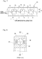
- Fig. 8 is a cross-sectional view of an angular contact ball bearing in which a conventional ball bearing retainer is used.
- Fig. 9 is a perspective view of the ball bearing retainer.
- Fig. 10 is a plan view as viewed from the outer diameter side of the ball bearing retainer.
- a conventional inner diameter restriction type rolling element guide retainer 30 has pockets Pt opened, each of pockets Pt is round as viewed from the radially outer side. That is, each pocket Pt has almost a cylindrical shape.
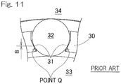
- Fig. 11 is a cross-sectional view taken along a line XI-XI in Fig. 8 .
- a gap "B" is formed when the retainer is positioned in a neutral position. Therefore, even if the retainer 30 is moved in the radial direction, ball guide is maintained so as to prevent the contact with an inner ring 33 and an outer ring 34.
- the ball 32 and the pocket Pt may come into contact with each other at points Q in the circumferential direction of the ball revolution, due to expansion of the retainer 30 by a centrifugal force, whirling or run-out thereof, or the like, and the ball 32 may strongly engage with the pocket Pt of the retainer 30. As a result, resistance or heat generation due to contact between the ball 32 and the pocket Pt may be increased.
- An object of the present invention is to provide a ball bearing retainer that allows high-speed operation while the ball bearing retainer is guided by balls.
- a ball bearing retainer of the present invention is directed to a ball guide retainer for a ball bearing which bearing includes: an inner ring; an outer ring; and balls interposed between the inner ring and the outer ring.
- the retainer includes an annular body formed with pockets at a plurality of portions thereof in a circumferential direction, the pockets holding the respective balls, in which case: the annular body includes annular parts and pillar parts, the annular parts being disposed on both sides in an axial direction, the pillar parts being disposed at a plurality of portions spaced in the circumferential direction and connecting between the annular parts; and the pockets are formed by the annular parts on both the sides in the axial direction and the pillar parts adjacent to each other in the circumferential direction.
- First contact portions of the pillar portions which contact portions contact with the balls in the circumferential direction, are formed by first planes that extend along the axial direction, and the balls are guided by the first planes, and the two first planes in each pocket extend radially inward from portions adjacent to a mid-position of the respective pillar parts in a thickness direction, over a predetermined distance, such that a distance between the two first planes in the circumferential direction is gradually reduced toward the distal ends thereof.
- a first contact portion of each pillar part, which contact portion contacts with the ball in the circumferential direction, is formed by the first plane that extends along the axial direction.
- a contact area which contacts with the ball can be reduced as compared to a round hole contact portion of a conventional inner diameter restriction type rolling element guide retainer. Therefore, heat generation that occurs partially at the first contact portion can be reduced. Accordingly, in the ball bearing retainer of the present invention, even when a centrifugal force acts in high-speed operation, heat generation at the ball and the first contact portion can be reduced, and high speed operation can be thus performed. Further, since ball guide is performed, the inner diameter surface of the outer ring and the outer diameter surface of the inner ring need not be finished by grinding, whereby the number of steps for processing can be reduced.
- Second contact portions of the annular parts which contact portions contact with the balls in the axial direction, may be formed by second planes that extend along the circumferential direction, and the balls may be guided by the second planes.
- a load due to contact between the ball and the pocket can be separated into a load that acts in the bearing rotation direction and a load that acts in the axial direction. Therefore, a contact area which contacts with the ball can be reduced as compared to a conventional inner diameter restriction type retainer, and heat generation that occurs partially at the contact portion can be reduced.
- Connection regions that connect between the pillar parts and the annular parts may have each a roundly-chamfered R-shape or an arc-shape.
- spaces for lubrication are formed between the ball and the connection regions having the R-shape or the arc-shape.
- air oil lubrication by the "spaces" being formed, oil can be smoothly supplied and discharged, and an appropriate amount of oil is constantly supplied to the contact portion between the ball and the retainer pocket.
- the "spaces" contribute to holding of grease in the vicinity of the contact portion, and the grease held in the "spaces” is supplied to the ball and the retainer pocket. As a result, lubrication reliability in a high speed operation is enhanced, and friction and wear due to contact are reduced.
- Connection regions that connect between the pillar parts and the annular parts may have each an arc-shape, arc-shaped regions of the connection regions may have each an arc-shaped surface obtained by an arc center being offset from a center of a corresponding one of the pockets, and a gap may be formed between the arc-shaped surface and each ball.
- a gap for lubrication is formed between each arc-shaped connection region and the ball.
- air oil lubrication by the "gap" being formed, oil can be smoothly supplied and discharged, and an appropriate amount of oil is constantly supplied to the contact portion between the ball and the retainer pocket.
- the "gap" contributes to holding of grease in the vicinity of the contact portion, and the grease held in the "gap” is supplied to the ball and the retainer pocket. As a result, lubrication reliability in a high speed operation is enhanced, and friction and wear due to contact are reduced.
- a radius of each connection region may be greater than or equal to 15% of a total width, in the axial direction, of each pocket.
- the radius of each connection region is determined, for example, based on a result of a test, simulation or the like. When the radius of the connection region is limited to the above numerical values, lubrication reliability in a high speed operation can be further enhanced.
- the ball bearing retainer of the present invention may be tailored to be used for an angular contact ball bearing or may be made of a resin.
- the ball bearing retainer made of a resin may be an injection molding product. In this case, as compared to production of retainers by machining, excellent mass productivity is obtained and cost can be reduced.
- the annular body may include two annular segments that confront each other in the axial direction of the annular body, and the pockets may be formed by the annular segments being combined so as to confront each other in the axial direction.
- a plurality of balls are inserted between raceway surfaces of the inner ring and the outer ring, and thereafter the two annular segments are combined from both sides in the axial direction, whereby the retainer can be easily assembled.
- the retainer is made of a resin and the two annular segments have the same shape, the two annular segments can be formed by using one kind of forming mold. Accordingly, cost for the mold and cost for the retainer can be thus reduced. Further, the two annular segments to be combined need not be separately handled, and as a result, the annular segments can be easily managed.
- Each of the first planes may have a width, which is the dimension in axial direction, that is reduced from a proximal end thereof toward the distal end thereof.
- a ball bearing of the present invention may be an angular contact ball bearing, for a spindle of a machine tool, which includes the retainer of the present invention.
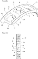
- FIG. 1 is a cross-sectional view of an angular contact ball bearing using the ball bearing retainer.
- the angular contact ball bearing includes: an inner ring 1; an outer ring 2; balls 4 interposed between the inner ring 1 and the outer ring 2; and a retainer 3 for retaining the balls 4.
- the retainer 3 is an inner diameter restriction type ball guide retainer.
- the balls 4 are formed as, for example, steel balls or ceramic balls.
- the retainer 3 includes an annular body 5 having therein pockets Pt formed at a plurality of portions along the circumferential direction thereof, and retains the balls 4, which are disposed between the inner ring 1 and the outer ring 2, in the pockets Pt.
- the retainer 3 is made of, for example, a resin, and is produced by injection molding.
- a resin material used for the retainer 3 a super engineering plastic, typified by a highly rigid PEEK resin that is advantageous in high speed rotation, which contains 20 to 40% of carbon fibers or glass fibers, or an engineering plastic, typified by a cost-friendly polyamide resin, which contains 20 to 40% of carbon fibers or glass fibers, can be used.
- Fig. 2A is a perspective view of the retainer 3, and Fig. 2B is an enlarged view of a main portion in Fig. 2A .
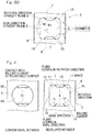
- Fig. 3A is a plan view of the retainer 3 as viewed from the outer diameter side, and Fig. 3B is an enlarged view of a main portion in Fig. 3A .
- the annular body 5 of the retainer 3 has: annular parts 6, 6 disposed on both sides in the axial direction; and pillar parts 7 disposed at a plurality of portions spaced in the circumferential direction so as to connect between the annular parts 6 and 6.
- Each pocket Pt is formed by the annular parts 6, 6, on both the sides in the axial direction, and the pillar parts 7, 7 adjacent to each other in the circumferential direction.
- each pocket Pt is formed in a substantially rectangular shape in a planar view when the retainer 3 is viewed from the outer diameter side.
- a pair of the pillar parts 7, 7 are disposed so as to confront each other in the circumferential direction.
- First contact portions in the pillar parts 7, which contact with the ball 4 ( Fig. 1 ) are formed by first planes 8 that extend along the axial direction.
- the ball 4 ( Fig. 1 ) is guided by the first planes 8.
- the first plane 8 of each pillar part 7 is referred to as a "rotation direction straight plane 8".
- the two rotation direction straight planes 8, 8 in each pocket Pt extend radially inward from portions adjacent to the mid-positions of the respective pillar parts 7 in the thickness direction, over a predetermined distance, such that the distance between the first planes 8, 8 in the circumferential direction is gradually reduced toward the distal ends thereof.
- Each rotation direction straight plane 8 has a width (dimension in the axial direction) that is reduced from the proximal end thereof toward the distal end thereof.
- the retainer 3 is formed as a ball guide inner diameter restriction type retainer by the rotation direction straight planes 8 in the pillar parts 7.
- Second contact portions of the annular parts 6 in the axial direction are formed by second planes 9 that extend along the circumferential direction.
- the ball 4 ( Fig. 1 ) is guided also by the second planes 9.
- Each second plane 9 of the annular part 6 is referred to as an "axial direction straight plane 9".
- the two axial direction straight planes 9, 9 are formed parallel to each other.
- the ball 4 ( Fig. 1 ) is guided by the rotation direction straight planes 8 and the axial direction straight planes 9. Therefore, a load due to contact between the ball 4 ( Fig. 1 ) and the pocket Pt can be separated into a load that acts in the bearing rotation direction and a load that acts in the axial direction.
- Connection regions 10 that connect between the pillar parts 7 and the annular parts 6 are each formed into a roundly-chamfered R-shape or arc-shape.
- the arc center of the R shape or the arc shape is positioned in the pocket Pt.
- the connection regions 10 are formed at four corners, respectively, of each pocket Pt that is shaped into a substantially rectangular shape.
- the radius of each connection region 10 is greater than or equal to 15% of the total width L1, in the axial direction, of the pocket Pt.
- the radius of each connection region 10 is determined, for example, according to a result of a test, simulation or the like.
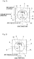
- Fig. 4 illustrates comparison between the retainer 3 (on the right side in Fig. 4 ) of the present embodiment and a conventional retainer 50 (on the left side in Fig. 4 ).
- the ball 4 contacts with a round hole surface 51 of a pocket Pt
- the retainer 3 of the present embodiment contacts with the rotation direction straight planes 8 of the pocket Pt.
- spaces 11 for lubrication are formed between the ball 4 and the connection regions 10 having the R-shape or the arc-shape.
- air oil lubrication by the spaces 11 being formed, oil can be smoothly supplied and discharged, and an appropriate amount of oil is constantly supplied to the contact portion between the ball 4 and the retainer pocket Pt.
- the spaces 11 contribute to holding of grease in the vicinity of the contact portion, and the grease held in the spaces 11 is supplied to the ball 4 and the retainer pocket Pt. As a result, lubrication reliability in a high speed operation is enhanced, and friction and wear due to contact are reduced.
- a first contact portion of each pillar part 7, which contacts with the ball 4 in the circumferential direction is formed by the first plane 8 that extends along the axial direction.
- a contact area which contacts with the ball 4 can be reduced as compared to a round hole contact portion of a conventional inner diameter restriction type rolling element guide retainer.
- heat generation that occurs partially at the contact portion can be reduced. Therefore, in the ball bearing retainer 3 of the present embodiment, even when a centrifugal force acts in high-speed operation, heat generation at the ball 4 and the first contact portion can be reduced, and high speed operation can be performed. Further, since ball guide is performed, the inner diameter surface of the outer ring and the outer diameter surface of the inner ring need not be finished by grinding, whereby the number of steps for processing can be reduced.
- each annular part 6, which contacts with the ball 4 in the axial direction is formed by the second plane 9 that extends along the circumferential direction, and the ball 4 is guided by the second plane 9.
- the ball 4 is guided by the first planes 8 of the pillar parts 7 and the second planes 9 of the annular parts 6, and therefore, a load due to contact between the ball 4 and the pocket Pt can be separated into a load that acts in the bearing rotation direction and a load that acts in the axial direction. Accordingly, a contact area which contacts with the ball can be reduced as compared to a conventional inner diameter restriction type retainer, and heat generation that occurs partially at the contact portion can be reduced.
- connection regions 10 that connect between the pillar parts 7 and the annular parts 6 are each arc-shaped.
- the arc-shaped portion of each connection region 10 is formed by an arc-shaped surface obtained by the arc center being offset from the center O1 of the pocket Pt in the axial direction and the circumferential direction.
- a gap is formed between each arc-shaped surface and the ball.
- arc-shaped portions of connection regions 10 are each formed by an arc-shaped surface obtained by the arc center being offset from the center O1 of the pocket Pt in the axial direction.
- a gap is formed between each arc-shaped surface and the ball.
- gaps for lubrication are formed between the arc-shaped connection regions 10 and the ball.
- air oil lubrication by the "gaps" being formed, oil can be smoothly supplied and discharged, and an appropriate amount of oil is constantly supplied to the contact portion between the ball and the retainer pocket Pt.
- the gaps contribute to holding of grease in the vicinity of the contact portion, and the grease held in the gaps is supplied to the ball and the retainer pocket Pt. As a result, lubrication reliability in a high speed operation is enhanced, and friction and wear due to contact are reduced.
- an annular body 5 of a retainer 3A has two divisional annular segments 12, 12 that can be divided in the axial direction.
- the two annular segments 12, 12 are combined, thereby forming the retainer 3A having a plurality of pockets Pt.
- the two annular segments 12, 12 have the same shape, and are combined with each other while being disposed oppositely in the axial direction.
- each pillar part 7 has an engagement surface 13 at which the two annular segments 12, 12 come into surface contact with each other when combined.
- the engagement surface 13 is formed by a plane that is perpendicular to the axial direction except for a portion adjacent to the center portion, in the circumferential direction, of each pillar part 7.
- the engagement surface 13 is formed at a position that axially deviates from the center, in the axial direction, of the annular body 5.
- the two divisional annular segments 12, 12 that can be divided in the axial direction are combined so as to confront each other in the axial direction, whereby the annular body 5 having a plurality of pockets Pt is formed. Therefore, a plurality of balls 4 ( Fig. 1 ) are inserted between raceway surfaces of the inner ring 1 and the outer ring 2 ( Fig. 1 ), and thereafter the two annular segments 12, 12 are combined from both sides in the axial direction, whereby the retainer 3A can be easily assembled.
- the retainer 3A is made of a resin, and the two annular segments 12, 12 have the same shape. Therefore, the two annular segments 12, 12 can be formed by using one kind of forming mold. Accordingly, cost for the mold and cost for the retainer 3A can be thus reduced. Further, the two annular segments 12, 12 to be combined need not be separately handled and the annular segments 12 can be easily managed.
Landscapes
- Engineering & Computer Science (AREA)
- General Engineering & Computer Science (AREA)
- Mechanical Engineering (AREA)
- Rolling Contact Bearings (AREA)
Claims (11)
- Kugelführungshalterung (3, 3A) für ein Kugellager, wobei das Lager Folgendes umfasst: einen Innenring (1); und einen Außenring (2); und Kugeln (4), die zwischen dem Innenring (1) und dem Außenring (2) angeordnet sind, wobei die Halterung Folgendes umfasst:einen ringförmigen Körper (5), der mit Taschen (Pt) an mehreren Abschnitten davon in einer Umfangsrichtung ausgebildet ist, wobei die Taschen (Pt) die jeweiligen Kugeln (4) fassen, wobeider ringförmige Körper (5) ringförmige Teile (6) und Säulenteile (7) umfasst, wobei die ringförmigen Teile (6) auf beiden Seiten in einer axialen Richtung angeordnet sind, wobei die Säulenteile (7) an mehreren Abschnitten in der Umfangsrichtung beabstandet angeordnet sind und eine Verbindung zwischen den ringförmigen Teilen (6) darstellen,die Taschen (Pt) durch die ringförmigen Teile (6) auf beiden seiten in der axialen Richtung und die in der Umfangsrichtung einander benachbarten Säulenteile (7) gebildet werden, underste Kontaktabschnitte der Säulenabschnitte, wobei die Kontaktabschnitte mit den Kugeln (4) in der Umfangsrichtung in Kontakt kommen, durch erste Ebenen (8), die sich in der Axialrichtung erstrecken, gebildet werden und die Kugeln (4) von den ersten Ebenen geführt werden,dadurch gekennzeichnet, dassdie zwei ersten Ebenen (8) in jeder Tasche (Pt) von Abschnitten neben einer Mittelposition der jeweiligen Säulenteile (7) in einer Dickenrichtung über einen vorbestimmten Abstand derart radial nach innen verlaufen, dass ein Abstand zwischen den zwei ersten Ebenen (8) in der Umfangsrichtung zu den distalen Enden davon hin allmählich reduziert wird.
- Halterung (3, 3A) für das Kugellager nach Anspruch 1, wobei zweite Kontaktabschnitte der ringförmigen Teile (6), wobei die Kontaktabschnitte mit den Kugeln (4) in der axialen Richtung in Kontakt kommen, durch zweite Ebenen (9), die in der Umfangsrichtung verlaufen, gebildet werden und die Kugeln (4) von den zweiten Ebenen (9) geführt werden.
- Halterung (3, 3A) für das Kugellager nach Anspruch 2, wobei Verbindungsbereiche (10), die eine Verbindung zwischen den Säulenteilen (7) und den ringförmigen Teilen (6) darstellen, jeweils eine rundschräge R-Form oder eine Bogenform aufweisen.
- Halterung (3, 3A) für das Kugellager nach Anspruch 2, wobei
Verbindungsbereiche (10), die eine Verbindung zwischen den Säulenteilen (7) und den ringförmigen Teilen (6) darstellen, jeweils eine Bogenform aufweisen,
bogenförmige Bereiche der Verbindungsbereiche (10) jeweils eine bogenförmige Fläche aufweisen, die dadurch erhalten wird, dass eine Bogenmitte von einer Mitte einer entsprechenden der Taschen (Pt) versetzt ist, und
ein Spalt zwischen der bogenförmigen Fläche und jeder Kugel (4) ausgebildet ist. - Halterung (3, 3A) für das Kugellager nach Anspruch 3 oder 4, wobei ein Radius jedes Verbindungsbereichs (10) größer gleich 15 % einer Gesamtbreite in der axialen Richtung jeder Tasche (Pt) ist.
- Halterung (3, 3A) für das Kugellager nach einem der Ansprüche 1-5, wobei die Halterung (3, 3A) auf die Verwendung für ein Schrägkugellager zugeschnitten ist.
- Halterung (3, 3A) für das Kugellager nach einem der Ansprüche 1-6, wobei die Halterung (3, 3A) aus einem Harz hergestellt ist.
- Halterung (3, 3A) für das Kugellager nach Anspruch 7, wobei die Halterung (3, 3A) ein Spritzgusserzeugnis ist.
- Halterung (3, 3A) für das Kugellager nach einem der Ansprüche 1-8, wobei
der ringförmige Körper (5) zwei ringförmige Segmente umfasst, die in der axialen Richtung des ringförmigen Körpers (5) einander gegenüberliegen, und
die Taschen (Pt) durch derartige Kombination der ringförmigen Segmente, dass sie in der axialen Richtung einander gegenüberliegen, gebildet werden. - Halterung (3, 3A) für das Kugellager nach einem der Ansprüche 1-9, wobei jede der ersten Ebenen (8) eine Breite, bei der es sich um die Abmessungen der axialen Richtung handelt, aufweist, die von einem proximalen Ende davon zu dem distalen Ende davon hin reduziert ist.
- Schrägkugellager für eine Spindel einer Werkzeugmaschine, wobei das Kugellager die Halterung (3, 3A) nach einem der Ansprüche 1-10 umfasst.
Applications Claiming Priority (3)
| Application Number | Priority Date | Filing Date | Title |
|---|---|---|---|
| JP2014199923 | 2014-09-30 | ||
| JP2015012108A JP6556454B2 (ja) | 2014-09-30 | 2015-01-26 | 玉軸受用保持器 |
| PCT/JP2015/076505 WO2016052232A1 (ja) | 2014-09-30 | 2015-09-17 | 玉軸受用保持器 |
Publications (3)
| Publication Number | Publication Date |
|---|---|
| EP3203099A1 EP3203099A1 (de) | 2017-08-09 |
| EP3203099A4 EP3203099A4 (de) | 2018-06-20 |
| EP3203099B1 true EP3203099B1 (de) | 2019-10-23 |
Family
ID=55864359
Family Applications (1)
| Application Number | Title | Priority Date | Filing Date |
|---|---|---|---|
| EP15847007.0A Active EP3203099B1 (de) | 2014-09-30 | 2015-09-17 | Kugellagerkäfig |
Country Status (6)
| Country | Link |
|---|---|
| US (1) | US10663001B2 (de) |
| EP (1) | EP3203099B1 (de) |
| JP (1) | JP6556454B2 (de) |
| KR (1) | KR102445802B1 (de) |
| CN (1) | CN107076206B (de) |
| TW (1) | TWI678478B (de) |
Families Citing this family (3)
| Publication number | Priority date | Publication date | Assignee | Title |
|---|---|---|---|---|
| DE102015224859A1 (de) * | 2015-12-10 | 2017-06-14 | Schaeffler Technologies AG & Co. KG | Kugellagerkäfig |
| TWI697632B (zh) * | 2018-01-26 | 2020-07-01 | 日商日本精工股份有限公司 | 斜角滾珠軸承 |
| CN112013030B (zh) * | 2020-08-20 | 2022-02-08 | 杭州康丰机械设备有限公司 | 一种工业防滑轴承 |
Family Cites Families (35)
| Publication number | Priority date | Publication date | Assignee | Title |
|---|---|---|---|---|
| US2327237A (en) * | 1940-01-20 | 1943-08-17 | Norma Hoffman Bearings Corp | Method for making retainers for antifriction bearings |
| US3588207A (en) * | 1970-01-15 | 1971-06-28 | Ind Tectonics Inc | Rolling element retainer having element retaining tabs |
| US3707753A (en) * | 1971-09-08 | 1973-01-02 | Trw Inc | Method of making cages |
| US3839531A (en) * | 1972-12-29 | 1974-10-01 | Textron Inc | Method for making a retaining ring for an antifriction bearing |
| JPS53135595A (en) | 1977-04-30 | 1978-11-27 | Toshiba Corp | Discharge unit |
| US4653938A (en) * | 1981-04-23 | 1987-03-31 | Rockwell International Corporation | Self-adjusting ball bearing cage |
| JPS5839817A (ja) * | 1981-09-03 | 1983-03-08 | Nippon Seiko Kk | ソリツド形コロ軸受用保持器の製造方法 |
| DE3247948C2 (de) | 1982-12-24 | 1985-10-17 | SKF GmbH, 8720 Schweinfurt | Käfig für Kugellager, insbesondere für Schrägkugellager |
| JPS611918A (ja) | 1984-06-13 | 1986-01-07 | Matsushita Electric Ind Co Ltd | 燃焼器具の制御装置 |
| JPS626532U (de) * | 1985-06-28 | 1987-01-16 | ||
| JP3611918B2 (ja) | 1996-02-29 | 2005-01-19 | Ntn株式会社 | アンギュラ玉軸受用樹脂保持器 |
| IT1293628B1 (it) * | 1997-07-18 | 1999-03-08 | Skf Ind Spa | Struttura di controllo di contenimento di corpi volventi di un cuscinetto a rotolamento, in particolare di un cuscinetto a rulli |
| JP2001012477A (ja) * | 1999-04-28 | 2001-01-16 | Nsk Ltd | 転がり軸受用保持器 |
| JP2002357226A (ja) * | 2001-03-28 | 2002-12-13 | Nsk Ltd | 玉軸受 |
| JP4192515B2 (ja) | 2002-07-16 | 2008-12-10 | 株式会社ジェイテクト | アンギュラ玉軸受用の樹脂保持器 |
| JP2004316757A (ja) * | 2003-04-15 | 2004-11-11 | Ntn Corp | 円筒ころ軸受および円筒ころ軸受用保持器 |
| JP4383766B2 (ja) * | 2003-04-18 | 2009-12-16 | Ntn株式会社 | アンギュラ玉軸受用の合成樹脂製保持器およびアンギュラ玉軸受 |
| JP2004324699A (ja) * | 2003-04-22 | 2004-11-18 | Nsk Ltd | 転がり軸受 |
| EP1803952B1 (de) * | 2004-10-22 | 2012-02-01 | NTN Corporation | Bearbeitetes gehäuse für zylinderrollenlager und herstellungsverfahren dafür |
| JP2006161882A (ja) | 2004-12-03 | 2006-06-22 | Ntn Corp | 転がり軸受用保持器 |
| JP2007147010A (ja) * | 2005-11-29 | 2007-06-14 | Ntn Corp | 玉軸受用保持器、玉軸受および工作機械 |
| JP2008133894A (ja) * | 2006-11-28 | 2008-06-12 | Ntn Corp | 玉軸受用保持器 |
| JP2009058039A (ja) * | 2007-08-31 | 2009-03-19 | Jtekt Corp | 転がり軸受用保持器 |
| TWM331056U (en) * | 2007-11-14 | 2008-04-21 | Tungpei Ind Co Ltd | Structure of retainer of ball bearing |
| DE102007057550A1 (de) * | 2007-11-29 | 2009-06-04 | Schaeffler Kg | Käfig für ein Wälzkörperlager sowie Verfahren zu dessen Herstellung |
| BRPI0915147B8 (pt) * | 2008-06-13 | 2021-11-09 | Ntn Toyo Bearing Co Ltd | Retentor, mancal de esfera com sulco profundo e mancal vedado |
| JP2011085153A (ja) * | 2009-10-13 | 2011-04-28 | Toyota Motor Corp | 転がり軸受 |
| DE102010038592B3 (de) * | 2010-07-29 | 2012-02-09 | Aktiebolaget Skf | Wälzlagerkäfig |
| JP5500014B2 (ja) * | 2010-09-09 | 2014-05-21 | 株式会社ジェイテクト | 玉軸受用保持器および玉軸受 |
| JP6370026B2 (ja) * | 2011-11-29 | 2018-08-08 | 日本精工株式会社 | 保持器および転がり軸受 |
| JP5507640B2 (ja) * | 2012-09-18 | 2014-05-28 | 凸版印刷株式会社 | 臭気吸着材、臭気検知キット、その使用方法 |
| JP2015048874A (ja) * | 2013-08-30 | 2015-03-16 | Ntn株式会社 | 玉軸受用保持器 |
| WO2016163527A1 (ja) * | 2015-04-10 | 2016-10-13 | Ntn株式会社 | 円すいころ軸受 |
| JP2017057982A (ja) * | 2015-09-18 | 2017-03-23 | Ntn株式会社 | 転がり玉軸受 |
| DE102015224859A1 (de) * | 2015-12-10 | 2017-06-14 | Schaeffler Technologies AG & Co. KG | Kugellagerkäfig |
-
2015
- 2015-01-26 JP JP2015012108A patent/JP6556454B2/ja active Active
- 2015-09-17 EP EP15847007.0A patent/EP3203099B1/de active Active
- 2015-09-17 KR KR1020177007617A patent/KR102445802B1/ko active Active
- 2015-09-17 CN CN201580052373.6A patent/CN107076206B/zh active Active
- 2015-09-25 TW TW104131689A patent/TWI678478B/zh active
-
2017
- 2017-03-20 US US15/463,541 patent/US10663001B2/en active Active
Non-Patent Citations (1)
| Title |
|---|
| None * |
Also Published As
| Publication number | Publication date |
|---|---|
| EP3203099A4 (de) | 2018-06-20 |
| KR20170063587A (ko) | 2017-06-08 |
| TW201632748A (zh) | 2016-09-16 |
| US10663001B2 (en) | 2020-05-26 |
| EP3203099A1 (de) | 2017-08-09 |
| TWI678478B (zh) | 2019-12-01 |
| CN107076206B (zh) | 2021-01-15 |
| JP6556454B2 (ja) | 2019-08-07 |
| KR102445802B1 (ko) | 2022-09-20 |
| US20170191528A1 (en) | 2017-07-06 |
| CN107076206A (zh) | 2017-08-18 |
| JP2016070485A (ja) | 2016-05-09 |
Similar Documents
| Publication | Publication Date | Title |
|---|---|---|
| EP3543553B1 (de) | Wälzlagerkäfig und wälzlager | |
| US20160178007A1 (en) | Ball bearing retainer | |
| JP6508196B2 (ja) | アンギュラ玉軸受 | |
| KR102018966B1 (ko) | 구름 베어링용 유지기, 및 구름 베어링, 그리고 구름 베어링용 유지기의 제조 방법 | |
| KR102013084B1 (ko) | 원추 롤러 베어링 및 원추 롤러 베어링의 제조 방법 | |
| KR101960144B1 (ko) | 앵귤러 볼 베어링 | |
| KR101988706B1 (ko) | 앵귤러 볼 베어링 | |
| US10663001B2 (en) | Ball bearing cage | |
| US20080019623A1 (en) | Rolling bearing and cage for rolling bearing | |
| JP6529209B2 (ja) | アンギュラ玉軸受 | |
| JP6493580B2 (ja) | アンギュラ玉軸受 | |
| KR20170015372A (ko) | 관형 유지기 및 앵귤러 볼 베어링 | |
| JP4537920B2 (ja) | 樹脂保持器並びに樹脂保持器金型および樹脂保持器の製造方法 | |
| JP2009275722A (ja) | 転がり軸受 | |
| JP6686482B2 (ja) | 転がり軸受用保持器、及び転がり軸受、並びに転がり軸受用保持器の製造方法 | |
| WO2016052232A1 (ja) | 玉軸受用保持器 | |
| CN117321313A (zh) | 滚动轴承保持架 | |
| JP2008008370A (ja) | 円筒ころ軸受用保持器 |
Legal Events
| Date | Code | Title | Description |
|---|---|---|---|
| STAA | Information on the status of an ep patent application or granted ep patent |
Free format text: STATUS: THE INTERNATIONAL PUBLICATION HAS BEEN MADE |
|
| PUAI | Public reference made under article 153(3) epc to a published international application that has entered the european phase |
Free format text: ORIGINAL CODE: 0009012 |
|
| STAA | Information on the status of an ep patent application or granted ep patent |
Free format text: STATUS: REQUEST FOR EXAMINATION WAS MADE |
|
| 17P | Request for examination filed |
Effective date: 20170413 |
|
| AK | Designated contracting states |
Kind code of ref document: A1 Designated state(s): AL AT BE BG CH CY CZ DE DK EE ES FI FR GB GR HR HU IE IS IT LI LT LU LV MC MK MT NL NO PL PT RO RS SE SI SK SM TR |
|
| AX | Request for extension of the european patent |
Extension state: BA ME |
|
| DAV | Request for validation of the european patent (deleted) | ||
| DAX | Request for extension of the european patent (deleted) | ||
| A4 | Supplementary search report drawn up and despatched |
Effective date: 20180524 |
|
| RIC1 | Information provided on ipc code assigned before grant |
Ipc: F16C 19/16 20060101ALI20180517BHEP Ipc: F16C 33/38 20060101AFI20180517BHEP Ipc: F16C 33/44 20060101ALI20180517BHEP |
|
| GRAP | Despatch of communication of intention to grant a patent |
Free format text: ORIGINAL CODE: EPIDOSNIGR1 |
|
| STAA | Information on the status of an ep patent application or granted ep patent |
Free format text: STATUS: GRANT OF PATENT IS INTENDED |
|
| INTG | Intention to grant announced |
Effective date: 20190507 |
|
| GRAS | Grant fee paid |
Free format text: ORIGINAL CODE: EPIDOSNIGR3 |
|
| GRAJ | Information related to disapproval of communication of intention to grant by the applicant or resumption of examination proceedings by the epo deleted |
Free format text: ORIGINAL CODE: EPIDOSDIGR1 |
|
| GRAL | Information related to payment of fee for publishing/printing deleted |
Free format text: ORIGINAL CODE: EPIDOSDIGR3 |
|
| STAA | Information on the status of an ep patent application or granted ep patent |
Free format text: STATUS: REQUEST FOR EXAMINATION WAS MADE |
|
| GRAR | Information related to intention to grant a patent recorded |
Free format text: ORIGINAL CODE: EPIDOSNIGR71 |
|
| STAA | Information on the status of an ep patent application or granted ep patent |
Free format text: STATUS: GRANT OF PATENT IS INTENDED |
|
| GRAA | (expected) grant |
Free format text: ORIGINAL CODE: 0009210 |
|
| STAA | Information on the status of an ep patent application or granted ep patent |
Free format text: STATUS: THE PATENT HAS BEEN GRANTED |
|
| INTC | Intention to grant announced (deleted) | ||
| INTG | Intention to grant announced |
Effective date: 20190911 |
|
| AK | Designated contracting states |
Kind code of ref document: B1 Designated state(s): AL AT BE BG CH CY CZ DE DK EE ES FI FR GB GR HR HU IE IS IT LI LT LU LV MC MK MT NL NO PL PT RO RS SE SI SK SM TR |
|
| REG | Reference to a national code |
Ref country code: GB Ref legal event code: FG4D |
|
| REG | Reference to a national code |
Ref country code: CH Ref legal event code: EP |
|
| REG | Reference to a national code |
Ref country code: IE Ref legal event code: FG4D |
|
| REG | Reference to a national code |
Ref country code: DE Ref legal event code: R096 Ref document number: 602015040482 Country of ref document: DE |
|
| REG | Reference to a national code |
Ref country code: AT Ref legal event code: REF Ref document number: 1193975 Country of ref document: AT Kind code of ref document: T Effective date: 20191115 |
|
| REG | Reference to a national code |
Ref country code: NL Ref legal event code: MP Effective date: 20191023 |
|
| REG | Reference to a national code |
Ref country code: LT Ref legal event code: MG4D |
|
| PG25 | Lapsed in a contracting state [announced via postgrant information from national office to epo] |
Ref country code: PL Free format text: LAPSE BECAUSE OF FAILURE TO SUBMIT A TRANSLATION OF THE DESCRIPTION OR TO PAY THE FEE WITHIN THE PRESCRIBED TIME-LIMIT Effective date: 20191023 Ref country code: LT Free format text: LAPSE BECAUSE OF FAILURE TO SUBMIT A TRANSLATION OF THE DESCRIPTION OR TO PAY THE FEE WITHIN THE PRESCRIBED TIME-LIMIT Effective date: 20191023 Ref country code: SE Free format text: LAPSE BECAUSE OF FAILURE TO SUBMIT A TRANSLATION OF THE DESCRIPTION OR TO PAY THE FEE WITHIN THE PRESCRIBED TIME-LIMIT Effective date: 20191023 Ref country code: BG Free format text: LAPSE BECAUSE OF FAILURE TO SUBMIT A TRANSLATION OF THE DESCRIPTION OR TO PAY THE FEE WITHIN THE PRESCRIBED TIME-LIMIT Effective date: 20200123 Ref country code: NL Free format text: LAPSE BECAUSE OF FAILURE TO SUBMIT A TRANSLATION OF THE DESCRIPTION OR TO PAY THE FEE WITHIN THE PRESCRIBED TIME-LIMIT Effective date: 20191023 Ref country code: LV Free format text: LAPSE BECAUSE OF FAILURE TO SUBMIT A TRANSLATION OF THE DESCRIPTION OR TO PAY THE FEE WITHIN THE PRESCRIBED TIME-LIMIT Effective date: 20191023 Ref country code: NO Free format text: LAPSE BECAUSE OF FAILURE TO SUBMIT A TRANSLATION OF THE DESCRIPTION OR TO PAY THE FEE WITHIN THE PRESCRIBED TIME-LIMIT Effective date: 20200123 Ref country code: GR Free format text: LAPSE BECAUSE OF FAILURE TO SUBMIT A TRANSLATION OF THE DESCRIPTION OR TO PAY THE FEE WITHIN THE PRESCRIBED TIME-LIMIT Effective date: 20200124 Ref country code: FI Free format text: LAPSE BECAUSE OF FAILURE TO SUBMIT A TRANSLATION OF THE DESCRIPTION OR TO PAY THE FEE WITHIN THE PRESCRIBED TIME-LIMIT Effective date: 20191023 Ref country code: PT Free format text: LAPSE BECAUSE OF FAILURE TO SUBMIT A TRANSLATION OF THE DESCRIPTION OR TO PAY THE FEE WITHIN THE PRESCRIBED TIME-LIMIT Effective date: 20200224 |
|
| PG25 | Lapsed in a contracting state [announced via postgrant information from national office to epo] |
Ref country code: IS Free format text: LAPSE BECAUSE OF FAILURE TO SUBMIT A TRANSLATION OF THE DESCRIPTION OR TO PAY THE FEE WITHIN THE PRESCRIBED TIME-LIMIT Effective date: 20200224 Ref country code: RS Free format text: LAPSE BECAUSE OF FAILURE TO SUBMIT A TRANSLATION OF THE DESCRIPTION OR TO PAY THE FEE WITHIN THE PRESCRIBED TIME-LIMIT Effective date: 20191023 Ref country code: HR Free format text: LAPSE BECAUSE OF FAILURE TO SUBMIT A TRANSLATION OF THE DESCRIPTION OR TO PAY THE FEE WITHIN THE PRESCRIBED TIME-LIMIT Effective date: 20191023 |
|
| PG25 | Lapsed in a contracting state [announced via postgrant information from national office to epo] |
Ref country code: AL Free format text: LAPSE BECAUSE OF FAILURE TO SUBMIT A TRANSLATION OF THE DESCRIPTION OR TO PAY THE FEE WITHIN THE PRESCRIBED TIME-LIMIT Effective date: 20191023 |
|
| REG | Reference to a national code |
Ref country code: DE Ref legal event code: R097 Ref document number: 602015040482 Country of ref document: DE |
|
| PG2D | Information on lapse in contracting state deleted |
Ref country code: IS |
|
| PG25 | Lapsed in a contracting state [announced via postgrant information from national office to epo] |
Ref country code: DK Free format text: LAPSE BECAUSE OF FAILURE TO SUBMIT A TRANSLATION OF THE DESCRIPTION OR TO PAY THE FEE WITHIN THE PRESCRIBED TIME-LIMIT Effective date: 20191023 Ref country code: EE Free format text: LAPSE BECAUSE OF FAILURE TO SUBMIT A TRANSLATION OF THE DESCRIPTION OR TO PAY THE FEE WITHIN THE PRESCRIBED TIME-LIMIT Effective date: 20191023 Ref country code: RO Free format text: LAPSE BECAUSE OF FAILURE TO SUBMIT A TRANSLATION OF THE DESCRIPTION OR TO PAY THE FEE WITHIN THE PRESCRIBED TIME-LIMIT Effective date: 20191023 Ref country code: CZ Free format text: LAPSE BECAUSE OF FAILURE TO SUBMIT A TRANSLATION OF THE DESCRIPTION OR TO PAY THE FEE WITHIN THE PRESCRIBED TIME-LIMIT Effective date: 20191023 Ref country code: ES Free format text: LAPSE BECAUSE OF FAILURE TO SUBMIT A TRANSLATION OF THE DESCRIPTION OR TO PAY THE FEE WITHIN THE PRESCRIBED TIME-LIMIT Effective date: 20191023 Ref country code: IS Free format text: LAPSE BECAUSE OF FAILURE TO SUBMIT A TRANSLATION OF THE DESCRIPTION OR TO PAY THE FEE WITHIN THE PRESCRIBED TIME-LIMIT Effective date: 20200223 |
|
| REG | Reference to a national code |
Ref country code: AT Ref legal event code: MK05 Ref document number: 1193975 Country of ref document: AT Kind code of ref document: T Effective date: 20191023 |
|
| PLBE | No opposition filed within time limit |
Free format text: ORIGINAL CODE: 0009261 |
|
| STAA | Information on the status of an ep patent application or granted ep patent |
Free format text: STATUS: NO OPPOSITION FILED WITHIN TIME LIMIT |
|
| PG25 | Lapsed in a contracting state [announced via postgrant information from national office to epo] |
Ref country code: SK Free format text: LAPSE BECAUSE OF FAILURE TO SUBMIT A TRANSLATION OF THE DESCRIPTION OR TO PAY THE FEE WITHIN THE PRESCRIBED TIME-LIMIT Effective date: 20191023 Ref country code: SM Free format text: LAPSE BECAUSE OF FAILURE TO SUBMIT A TRANSLATION OF THE DESCRIPTION OR TO PAY THE FEE WITHIN THE PRESCRIBED TIME-LIMIT Effective date: 20191023 Ref country code: IT Free format text: LAPSE BECAUSE OF FAILURE TO SUBMIT A TRANSLATION OF THE DESCRIPTION OR TO PAY THE FEE WITHIN THE PRESCRIBED TIME-LIMIT Effective date: 20191023 |
|
| 26N | No opposition filed |
Effective date: 20200724 |
|
| PG25 | Lapsed in a contracting state [announced via postgrant information from national office to epo] |
Ref country code: AT Free format text: LAPSE BECAUSE OF FAILURE TO SUBMIT A TRANSLATION OF THE DESCRIPTION OR TO PAY THE FEE WITHIN THE PRESCRIBED TIME-LIMIT Effective date: 20191023 Ref country code: SI Free format text: LAPSE BECAUSE OF FAILURE TO SUBMIT A TRANSLATION OF THE DESCRIPTION OR TO PAY THE FEE WITHIN THE PRESCRIBED TIME-LIMIT Effective date: 20191023 |
|
| REG | Reference to a national code |
Ref country code: CH Ref legal event code: PL |
|
| GBPC | Gb: european patent ceased through non-payment of renewal fee |
Effective date: 20200917 |
|
| REG | Reference to a national code |
Ref country code: BE Ref legal event code: MM Effective date: 20200930 |
|
| PG25 | Lapsed in a contracting state [announced via postgrant information from national office to epo] |
Ref country code: LU Free format text: LAPSE BECAUSE OF NON-PAYMENT OF DUE FEES Effective date: 20200917 |
|
| PG25 | Lapsed in a contracting state [announced via postgrant information from national office to epo] |
Ref country code: FR Free format text: LAPSE BECAUSE OF NON-PAYMENT OF DUE FEES Effective date: 20200930 |
|
| PG25 | Lapsed in a contracting state [announced via postgrant information from national office to epo] |
Ref country code: LI Free format text: LAPSE BECAUSE OF NON-PAYMENT OF DUE FEES Effective date: 20200930 Ref country code: IE Free format text: LAPSE BECAUSE OF NON-PAYMENT OF DUE FEES Effective date: 20200917 Ref country code: GB Free format text: LAPSE BECAUSE OF NON-PAYMENT OF DUE FEES Effective date: 20200917 Ref country code: BE Free format text: LAPSE BECAUSE OF NON-PAYMENT OF DUE FEES Effective date: 20200930 Ref country code: CH Free format text: LAPSE BECAUSE OF NON-PAYMENT OF DUE FEES Effective date: 20200930 |
|
| PG25 | Lapsed in a contracting state [announced via postgrant information from national office to epo] |
Ref country code: TR Free format text: LAPSE BECAUSE OF FAILURE TO SUBMIT A TRANSLATION OF THE DESCRIPTION OR TO PAY THE FEE WITHIN THE PRESCRIBED TIME-LIMIT Effective date: 20191023 Ref country code: MT Free format text: LAPSE BECAUSE OF FAILURE TO SUBMIT A TRANSLATION OF THE DESCRIPTION OR TO PAY THE FEE WITHIN THE PRESCRIBED TIME-LIMIT Effective date: 20191023 Ref country code: CY Free format text: LAPSE BECAUSE OF FAILURE TO SUBMIT A TRANSLATION OF THE DESCRIPTION OR TO PAY THE FEE WITHIN THE PRESCRIBED TIME-LIMIT Effective date: 20191023 |
|
| PG25 | Lapsed in a contracting state [announced via postgrant information from national office to epo] |
Ref country code: MK Free format text: LAPSE BECAUSE OF FAILURE TO SUBMIT A TRANSLATION OF THE DESCRIPTION OR TO PAY THE FEE WITHIN THE PRESCRIBED TIME-LIMIT Effective date: 20191023 Ref country code: MC Free format text: LAPSE BECAUSE OF FAILURE TO SUBMIT A TRANSLATION OF THE DESCRIPTION OR TO PAY THE FEE WITHIN THE PRESCRIBED TIME-LIMIT Effective date: 20191023 |
|
| PGFP | Annual fee paid to national office [announced via postgrant information from national office to epo] |
Ref country code: DE Payment date: 20250730 Year of fee payment: 11 |