EP3203119A1 - Ensemble d'engrenages - Google Patents
Ensemble d'engrenages Download PDFInfo
- Publication number
- EP3203119A1 EP3203119A1 EP17150375.8A EP17150375A EP3203119A1 EP 3203119 A1 EP3203119 A1 EP 3203119A1 EP 17150375 A EP17150375 A EP 17150375A EP 3203119 A1 EP3203119 A1 EP 3203119A1
- Authority
- EP
- European Patent Office
- Prior art keywords
- gear
- positioning
- gear assembly
- gears
- ring
- Prior art date
- Legal status (The legal status is an assumption and is not a legal conclusion. Google has not performed a legal analysis and makes no representation as to the accuracy of the status listed.)
- Withdrawn
Links
- 230000000712 assembly Effects 0.000 description 3
- 238000000429 assembly Methods 0.000 description 3
- 229920001971 elastomer Polymers 0.000 description 3
- 238000005096 rolling process Methods 0.000 description 3
- 239000005060 rubber Substances 0.000 description 3
- 238000002485 combustion reaction Methods 0.000 description 2
- 238000007796 conventional method Methods 0.000 description 2
- 238000006073 displacement reaction Methods 0.000 description 2
- 239000000463 material Substances 0.000 description 2
- 229920000459 Nitrile rubber Polymers 0.000 description 1
- 230000003466 anti-cipated effect Effects 0.000 description 1
- 230000006835 compression Effects 0.000 description 1
- 238000007906 compression Methods 0.000 description 1
- 230000000694 effects Effects 0.000 description 1
- 230000033001 locomotion Effects 0.000 description 1
- 238000004519 manufacturing process Methods 0.000 description 1
- 230000013011 mating Effects 0.000 description 1
- 239000012858 resilient material Substances 0.000 description 1
Images

Classifications
-
- F—MECHANICAL ENGINEERING; LIGHTING; HEATING; WEAPONS; BLASTING
- F16—ENGINEERING ELEMENTS AND UNITS; GENERAL MEASURES FOR PRODUCING AND MAINTAINING EFFECTIVE FUNCTIONING OF MACHINES OR INSTALLATIONS; THERMAL INSULATION IN GENERAL
- F16H—GEARING
- F16H57/00—General details of gearing
- F16H57/12—Arrangements for adjusting or for taking-up backlash not provided for elsewhere
-
- F—MECHANICAL ENGINEERING; LIGHTING; HEATING; WEAPONS; BLASTING
- F16—ENGINEERING ELEMENTS AND UNITS; GENERAL MEASURES FOR PRODUCING AND MAINTAINING EFFECTIVE FUNCTIONING OF MACHINES OR INSTALLATIONS; THERMAL INSULATION IN GENERAL
- F16H—GEARING
- F16H1/00—Toothed gearings for conveying rotary motion
- F16H1/02—Toothed gearings for conveying rotary motion without gears having orbital motion
- F16H1/04—Toothed gearings for conveying rotary motion without gears having orbital motion involving only two intermeshing members
- F16H1/06—Toothed gearings for conveying rotary motion without gears having orbital motion involving only two intermeshing members with parallel axes
-
- F—MECHANICAL ENGINEERING; LIGHTING; HEATING; WEAPONS; BLASTING
- F16—ENGINEERING ELEMENTS AND UNITS; GENERAL MEASURES FOR PRODUCING AND MAINTAINING EFFECTIVE FUNCTIONING OF MACHINES OR INSTALLATIONS; THERMAL INSULATION IN GENERAL
- F16H—GEARING
- F16H55/00—Elements with teeth or friction surfaces for conveying motion; Worms, pulleys or sheaves for gearing mechanisms
- F16H55/02—Toothed members; Worms
- F16H55/12—Toothed members; Worms with body or rim assembled out of detachable parts
-
- F—MECHANICAL ENGINEERING; LIGHTING; HEATING; WEAPONS; BLASTING
- F16—ENGINEERING ELEMENTS AND UNITS; GENERAL MEASURES FOR PRODUCING AND MAINTAINING EFFECTIVE FUNCTIONING OF MACHINES OR INSTALLATIONS; THERMAL INSULATION IN GENERAL
- F16H—GEARING
- F16H55/00—Elements with teeth or friction surfaces for conveying motion; Worms, pulleys or sheaves for gearing mechanisms
- F16H55/02—Toothed members; Worms
- F16H55/14—Construction providing resilience or vibration-damping
-
- F—MECHANICAL ENGINEERING; LIGHTING; HEATING; WEAPONS; BLASTING
- F16—ENGINEERING ELEMENTS AND UNITS; GENERAL MEASURES FOR PRODUCING AND MAINTAINING EFFECTIVE FUNCTIONING OF MACHINES OR INSTALLATIONS; THERMAL INSULATION IN GENERAL
- F16H—GEARING
- F16H55/00—Elements with teeth or friction surfaces for conveying motion; Worms, pulleys or sheaves for gearing mechanisms
- F16H55/02—Toothed members; Worms
- F16H55/17—Toothed wheels
- F16H55/18—Special devices for taking up backlash
-
- F—MECHANICAL ENGINEERING; LIGHTING; HEATING; WEAPONS; BLASTING
- F16—ENGINEERING ELEMENTS AND UNITS; GENERAL MEASURES FOR PRODUCING AND MAINTAINING EFFECTIVE FUNCTIONING OF MACHINES OR INSTALLATIONS; THERMAL INSULATION IN GENERAL
- F16H—GEARING
- F16H57/00—General details of gearing
- F16H57/0006—Vibration-damping or noise reducing means specially adapted for gearings
-
- F—MECHANICAL ENGINEERING; LIGHTING; HEATING; WEAPONS; BLASTING
- F16—ENGINEERING ELEMENTS AND UNITS; GENERAL MEASURES FOR PRODUCING AND MAINTAINING EFFECTIVE FUNCTIONING OF MACHINES OR INSTALLATIONS; THERMAL INSULATION IN GENERAL
- F16H—GEARING
- F16H57/00—General details of gearing
- F16H57/02—Gearboxes; Mounting gearing therein
- F16H57/02004—Gearboxes; Mounting gearing therein the gears being positioned relative to one another by rolling members or by specially adapted surfaces on the gears, e.g. by a rolling surface with the diameter of the pitch circle
-
- F—MECHANICAL ENGINEERING; LIGHTING; HEATING; WEAPONS; BLASTING
- F16—ENGINEERING ELEMENTS AND UNITS; GENERAL MEASURES FOR PRODUCING AND MAINTAINING EFFECTIVE FUNCTIONING OF MACHINES OR INSTALLATIONS; THERMAL INSULATION IN GENERAL
- F16H—GEARING
- F16H57/00—General details of gearing
- F16H57/12—Arrangements for adjusting or for taking-up backlash not provided for elsewhere
- F16H2057/126—Self-adjusting during operation, e.g. by a spring
- F16H2057/127—Self-adjusting during operation, e.g. by a spring using springs
Definitions
- This disclosure relates generally to a gear assembly and particularly, although not exclusively, relates to a gear assembly for an internal combustion engine.
- Gear tooth meshing is a critical feature that often requires of control gear tooth positions to micron levels for optimum efficiency, durability and low noise (rattle and whine).
- manufacturing tolerances, component dynamics and differences in thermal expansion rates mean that it is very difficult to keep the mating gear teeth in the optimum positions relative to one another.
- the conventional methods of dealing with this are to introduce tight tolerance control, similar materials, and backlash control features to keep the backlash and positional error to a minimum. These conventional methods add significant cost, weight and complexity to gear drive systems.
- backlash control features like scissor gears
- a gear assembly comprising first and second gears configured to mesh with each other, the first gear comprising inner and outer ring elements and a resilient ring element disposed between and coupled to the inner and outer ring elements, the outer ring element comprising first gear teeth which mesh with second gear teeth of the second gear, wherein the first and second gears each comprise a positioning ring axially spaced apart from the first and second gear teeth, the positioning rings being configured to engage each other and limit the position of the first and second gear teeth relative to each other.
- the first gear positioning ring may be connected to the first gear outer ring element.
- the first gear positioning ring may be integral with the first gear outer ring element.
- the first gear positioning ring may be concentric with the first gear outer ring element.
- the first and/or second gear positioning rings may comprise a resilient outer layer.
- Each of the first and second gear positioning rings may have an outer diameter less than an outside diameter of the respective first and second gear.
- the outside diameter may be measured from tops of the respective first and second gear teeth.
- Each of the first and second gear positioning rings may have an outer diameter greater than a root diameter of the respective first and second gear.
- the root diameter may be measured from roots or bases of the respective first and second gear teeth.
- the first and second gear positioning rings may have outer diameters that are approximately the average of the outside and root diameters of the respective first and second gears.
- the first and second gear positioning rings may be circular.
- An outer diameter of the first gear positioning ring may substantially correspond to a pitch circle diameter of the first gear.
- An outer diameter of the second gear positioning ring may substantially correspond to a pitch circle diameter of the second gear.
- the pitch circles of each gear may correspond to circles with diameters that result in the same gear ratio as the first and second gears, the circles contacting and rolling without slip.
- the pitch circle diameter of each gear may be between, e.g. midway between, the outside diameter and the root diameter of the respective gear.
- the first and second gears may be spaced apart such that the inner and outer ring elements of the first gear may not be concentric.
- the resilient element may thus be pre-stressed prior to use.
- the gear assembly e.g. spacing apart of the first and second gears, size of resilient ring element, and/or a resilience of the resilient element, may be configured such that the gear positioning rings remain, e.g. substantially, in contact during use of the gear assembly. Rotational axes of the first and second gears may move apart, e.g. due to thermal expansions, bearing imperfections, dynamic motions of the shafts, etc.
- the pre-stress of the resilient element may be such that the first and second gears remain urged together under action of the resilient element despite the rotational axes of the first and second gears moving apart.
- the gear comprising the resilient element may be either a driving or driven gear.
- the first and second gears may each comprise a further positioning ring axially spaced apart from the first and second gear teeth.
- the further positioning rings may be provided on an opposing side of the first and second gear teeth to the positioning rings.
- the further positioning rings may be configured to engage each other and limit the position of the first and second gear teeth relative to each other. Features described in respect of the positioning rings may apply equally to further positioning ring.
- the resilient ring element may be bonded to the outer and/or inner ring elements. Additionally or alternatively, the resilient ring element may be coupled to the outer and/or inner ring elements by virtue of one or more splines.
- An engine or motor vehicle may comprise the above-mentioned gear assembly.
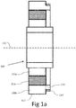
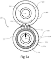
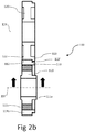
- a gear assembly 100 comprises a first gear 110 and a second gear 120.
- the first and second gears 110, 120 are configured to mesh with each other such that rotation of one of the gears causes the other to rotate.
- the first gear 110 comprises first gear teeth 112 and the second gear comprises second gear teeth 122, the first gear teeth 112 meshing with the second gear teeth 122.
- the first and second gears 110, 120 rotate about respective axes 114, 124.
- the rotational axes 114, 124 may be substantially parallel, although in alternative arrangements the rotational axes may be non parallel.
- the first and second gear teeth 112, 122 may extend in a direction parallel to the rotational axes 114, 124.
- first and second gear teeth 112, 122 may not extend in a direction parallel to the rotational axes 114, 124, for example the gear teeth may be helical in arrangement such that the teeth form a helix about the respective rotational axis.
- the first gear 110 comprises an inner ring element 111a and an outer ring element 111b, the outer ring element 111b being disposed radially outer of the inner ring element 111a.
- the inner ring element 111a is connected to or comprises a hub for receiving a shaft (not shown).
- the inner ring element 111a may be integral with a shaft.
- the outer ring element 111b comprises the first gear teeth 112.
- a resilient ring element 111c is provided between the inner and outer ring elements 111a, 111b.
- the resilient ring element 111c is coupled to each of the inner and outer ring elements 111a, 111b such that rotation of the inner ring element may be transferred to the outer ring element or vice versa.
- the resilient ring element 111c may be bonded to each of the inner and outer ring elements 111a, 111b.
- the resilient ring element 111c may comprise splines or any other features, which engage corresponding features in the inner and/or outer ring elements 111a, 111b to rotatably couple the ring elements together.
- the resilient ring element 111c is made of a resilient material that allows the outer ring element 111b to be displaced in a radial direction relative to the inner ring element 111a.
- the resilient ring element 111c may be made from a rubber type material, such as Hydrogenated Nitrile Butadiene Rubber (HNBR).
- HNBR Hydrogenated Nitrile Butadiene Rubber
- the rotational axes 114, 124 of the first and second gears 110, 120 may be spaced apart such that the resilient ring element 111c is pre-stressed. For example, a portion of the resilient ring element 111c that is closest to where the first and second gears mesh may be under compression. By contrast, a portion of the resilient ring element 111c furthest from where the first and second gears mesh may be in tension.
- the first and second gears 110, 120 may each comprise a positioning ring 113, 123.
- the first and second positioning rings 113, 123 are axially spaced apart from the gear teeth 112, 122 of the respective first and second gear.
- the first and second positioning rings 113, 123 are provided to one side of the first and second gear teeth 112, 122 respectively.
- the first and second positioning rings 113, 123 are configured to contact each other when the first and second gears mesh.
- the first and second positioning rings 113, 123 limit the position of the first and second gear teeth 112, 122 relative to each other.
- the first gear positioning ring 113 is connected to the first gear outer ring element 111b, and in particular may be integral with the first gear outer ring element 111b. Accordingly, the first gear positioning ring 113 may move with the first gear outer ring element 111b relative to the inner ring element 111a.
- the first gear positioning ring 113 may be concentric with the first gear outer ring element 111b.
- the first gear positioning ring 113 may not necessarily be concentric with the inner ring element 111a during use of the gear assembly since the inner and outer ring elements may not be concentric during such use.
- the first and second gear positioning rings may form a rolling contact.
- one or both of the first and second gear positioning rings 113, 123 may comprise an optional resilient outer layer 113', e.g., in the form of a rubber tyre.
- the second gear positioning ring 123 may be connected to the remainder of the second gear 120, in particular the second gear positioning ring 123 may be coupled to a portion of the second gear on which the second gear teeth 122 are provided.
- the second gear teeth 122 may be rigidly connected to a hub of the second gear and may remain concentric with the rotational axis 124.
- the second gear 120 may comprise an intermediate resilient element similar to that described in respect of the first gear 110.
- the first and second gear positioning rings 113, 123 may be circular. Each of the first and second gear positioning rings 113, 123 may have an outer diameter that allows the gear teeth to mesh, but also allows the gear positioning rings to contact each other. For example, the first and second gear positioning rings may have outer diameters less than an outside diameter of the respective first and second gear. The outside diameter of a gear may be measured from tops of the gear teeth. Similarly, each of the first and second gear positioning rings 113, 123 may have an outer diameter greater than a root diameter of the respective first and second gears. The root diameter may be measured from roots of the gear teeth, e.g., between the tops of the teeth.
- the outer diameters of the positioning rings may substantially correspond to a pitch circle diameter of the respective gear.
- the outer diameter of the first gear positioning ring 113 may substantially correspond to a pitch circle diameter of the first gear 110.
- the outer diameter of the second gear positioning ring 123 may substantially correspond to a pitch circle diameter of the second gear 120.
- the pitch circles of each gear may correspond to circles with the same gear ratio as the first and second gears, the circles contacting and rolling without slip. It will be appreciated, that the pitch circle diameter of each gear may be between the outside diameter and the root diameter of the respective gear.
- the rotational axes 114, 124 may be spaced apart such that the resilient ring element 111c remains in a stressed condition during use of the gear assembly 100.
- the resilient element 111c may thus ensure that the first and second gear positioning rings 113, 123 remain in contact during use and that backlash between the gears may be minimised.
- the first and second gear positioning rings 113, 123 may also ensure that the teeth of one gear do not extend too far into the gaps between teeth of the other gear, thereby avoiding the gears locking, generating imperfect contact and/or noise.
- the gear assembly 100 may be configured such that the gear positioning rings 113, 123 remain in contact during use of the gear assembly.
- the diameter of the gears, the resilience of the resilient element, the radial thickness of the resilient element and/or the spacing apart of the first and second gears may be selected such that the resilient ring element 111c remains in a stressed state during normal use of the gear assembly. In the stressed state, the resilient element 111c provides a force urging the first gear 110 into mesh with the second gear 120.
- Normal use of the gear assembly 100 corresponds to anticipated variations in the axes of rotation 114, 124, e.g., as caused by thermal expansions, bearing tolerances and/or shaft/bearing dynamics.
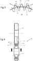
- a gear assembly 200 may comprise first and second gears 210, 220 each comprising a further positioning ring 213, 223 in addition to the positioning rings 113, 123.
- the further positioning rings are axially spaced apart from the first and second gear teeth and are provided on an opposing side of the first and second gear teeth to the positioning rings 113, 123.
- the further positioning rings 213, 223 are configured to engage each other and limit the position of the first and second gear teeth relative to each other. It will be appreciated that features described above in respect of the positioning rings 113, 123 may apply equally to the further positioning rings 213, 223.
- one or both of the further positioning rings 213, 223 may comprise an optional resilient outer layer 213', e.g., in the form of a rubber tyre.
- the gear assemblies 100, 200 described herein may be used in an internal combustion engine.
- the gear assemblies 100, 200 may be used to rotatably couple a crankshaft to a balancer shaft of the engine.
- Such shafts may be subject to radial displacements due to the loads applied.
- the gear assemblies described herein may help to ensure that the gears remain engaged during such radial displacements and limit backlash between the gears.
Landscapes
- Engineering & Computer Science (AREA)
- General Engineering & Computer Science (AREA)
- Mechanical Engineering (AREA)
- Gears, Cams (AREA)
- Retarders (AREA)
- Gear Transmission (AREA)
Applications Claiming Priority (1)
| Application Number | Priority Date | Filing Date | Title |
|---|---|---|---|
| GB1602148.7A GB2547035B (en) | 2016-02-05 | 2016-02-05 | Gear assembly |
Publications (1)
| Publication Number | Publication Date |
|---|---|
| EP3203119A1 true EP3203119A1 (fr) | 2017-08-09 |
Family
ID=55641906
Family Applications (1)
| Application Number | Title | Priority Date | Filing Date |
|---|---|---|---|
| EP17150375.8A Withdrawn EP3203119A1 (fr) | 2016-02-05 | 2017-01-05 | Ensemble d'engrenages |
Country Status (6)
| Country | Link |
|---|---|
| US (1) | US10641381B2 (fr) |
| EP (1) | EP3203119A1 (fr) |
| CN (1) | CN107044536A (fr) |
| GB (1) | GB2547035B (fr) |
| MX (1) | MX2017001703A (fr) |
| RU (1) | RU2017101695A (fr) |
Families Citing this family (2)
| Publication number | Priority date | Publication date | Assignee | Title |
|---|---|---|---|---|
| DE102018125537A1 (de) * | 2018-10-15 | 2020-04-16 | Trw Automotive Gmbh | Mehrteiliges Zahnrad sowie Getriebe für ein Lenksystem |
| US20210310542A1 (en) * | 2019-12-27 | 2021-10-07 | Leonidas Kyros Kontopoulos | Power transmission system with at least one engagement component and divided gear wheels |
Citations (5)
| Publication number | Priority date | Publication date | Assignee | Title |
|---|---|---|---|---|
| US1548545A (en) * | 1923-04-19 | 1925-08-04 | Bbc Brown Boveri & Cie | Apparatus for balancing the axial thrust in single helical toothed wheel gearing |
| CH277108A (it) * | 1948-01-24 | 1951-08-15 | Ferrajoli Vincenzo | Ingranaggio ad assi complanari. |
| US3206993A (en) * | 1962-08-09 | 1965-09-21 | Niemann Gustav | Spur-gear trains |
| DE102011120676A1 (de) * | 2011-12-02 | 2013-06-06 | Getrag Getriebe- Und Zahnradfabrik Hermann Hagenmeyer Gmbh & Cie Kg | Verfahren zum Herstellen eines Zahnrades |
| DE102014225192A1 (de) * | 2014-02-13 | 2015-08-13 | Miba Sinter Austria Gmbh | Zahnrad |
Family Cites Families (24)
| Publication number | Priority date | Publication date | Assignee | Title |
|---|---|---|---|---|
| US277108A (en) * | 1883-05-08 | Clamp for sewing-machine attachments | ||
| US1427721A (en) * | 1922-04-17 | 1922-08-29 | Martin O Christenson | Noiseless gear wheel |
| US2307129A (en) * | 1940-04-05 | 1943-01-05 | Int Projector Corp | Shockproof gear |
| US3002464A (en) * | 1958-03-17 | 1961-10-03 | Clinton W Lee | Rotary gear pump, bearings and sealing means therefor |
| JPH0721289B2 (ja) * | 1983-11-15 | 1995-03-08 | 松下電器産業株式会社 | ウオームギヤ付モータの衝撃トルク吸収装置 |
| US4674351A (en) * | 1985-12-23 | 1987-06-23 | Sundstrand Corporation | Compliant gear |
| US5452622A (en) * | 1993-02-09 | 1995-09-26 | Magi, L.P. | Stress dissipation gear |
| US5307705A (en) * | 1993-02-09 | 1994-05-03 | Fenelon Paul J | Stress dissipation gear and method of making same |
| DE19856100C2 (de) * | 1998-12-04 | 2001-08-23 | Siemens Ag | Getriebemotor-Stellantrieb, insbesondere motorischer Schließteil-Antrieb für ein Kraftfahrzeug |
| JP2001116114A (ja) * | 1999-10-15 | 2001-04-27 | Nok Corp | 歯車装置 |
| JP2001132822A (ja) * | 1999-11-01 | 2001-05-18 | Nok Corp | 歯車装置 |
| DE10347780A1 (de) * | 2003-10-15 | 2005-05-12 | Zf Lenksysteme Gmbh | Zahnrad für Schraubradgetriebe |
| JP4375720B2 (ja) * | 2003-12-19 | 2009-12-02 | 株式会社エンプラス | 樹脂歯車 |
| EP1555584A1 (fr) | 2004-01-13 | 2005-07-20 | Rolex S.A. | Mobile denté à rattrapage de jeu, engrenage et utilisation de cet engrenage |
| JP4640777B2 (ja) | 2005-01-31 | 2011-03-02 | 株式会社エンプラス | 樹脂製歯車装置 |
| US8225689B2 (en) * | 2006-07-27 | 2012-07-24 | Caterpillar Inc. | Compliant gear assembly, engine and gear train operating method |
| US7658124B2 (en) * | 2006-07-27 | 2010-02-09 | Caterpillar Inc. | Compliant gear assembly and work machine using same |
| JP5430538B2 (ja) * | 2010-03-09 | 2014-03-05 | ジヤトコ株式会社 | ギア構造 |
| AT510575B1 (de) | 2010-09-24 | 2012-05-15 | Miba Sinter Austria Gmbh | Zahnrad |
| CN102434649A (zh) | 2010-09-29 | 2012-05-02 | 富泰华工业(深圳)有限公司 | 传动件及带有该传动件的传动机构 |
| JP5240405B1 (ja) * | 2011-09-14 | 2013-07-17 | トヨタ自動車株式会社 | はすば歯車および動力伝達装置 |
| AT514590B1 (de) * | 2014-02-13 | 2015-02-15 | Metaldyne Internat Deutschland Gmbh | Zahnrad |
| JP2016098906A (ja) * | 2014-11-21 | 2016-05-30 | Ntn株式会社 | 歯車およびこれを備えた電動アクチュエータ |
| NL2015189B1 (en) * | 2015-07-18 | 2017-02-07 | Vcst Ind Products Bvba | Scissor gear assembly. |
-
2016
- 2016-02-05 GB GB1602148.7A patent/GB2547035B/en not_active Expired - Fee Related
-
2017
- 2017-01-05 EP EP17150375.8A patent/EP3203119A1/fr not_active Withdrawn
- 2017-01-19 RU RU2017101695A patent/RU2017101695A/ru not_active Application Discontinuation
- 2017-01-25 CN CN201710055991.7A patent/CN107044536A/zh not_active Withdrawn
- 2017-01-30 US US15/419,057 patent/US10641381B2/en not_active Expired - Fee Related
- 2017-02-07 MX MX2017001703A patent/MX2017001703A/es unknown
Patent Citations (5)
| Publication number | Priority date | Publication date | Assignee | Title |
|---|---|---|---|---|
| US1548545A (en) * | 1923-04-19 | 1925-08-04 | Bbc Brown Boveri & Cie | Apparatus for balancing the axial thrust in single helical toothed wheel gearing |
| CH277108A (it) * | 1948-01-24 | 1951-08-15 | Ferrajoli Vincenzo | Ingranaggio ad assi complanari. |
| US3206993A (en) * | 1962-08-09 | 1965-09-21 | Niemann Gustav | Spur-gear trains |
| DE102011120676A1 (de) * | 2011-12-02 | 2013-06-06 | Getrag Getriebe- Und Zahnradfabrik Hermann Hagenmeyer Gmbh & Cie Kg | Verfahren zum Herstellen eines Zahnrades |
| DE102014225192A1 (de) * | 2014-02-13 | 2015-08-13 | Miba Sinter Austria Gmbh | Zahnrad |
Also Published As
| Publication number | Publication date |
|---|---|
| RU2017101695A (ru) | 2018-07-19 |
| US20170227116A1 (en) | 2017-08-10 |
| GB2547035A (en) | 2017-08-09 |
| GB201602148D0 (en) | 2016-03-23 |
| GB2547035B (en) | 2019-03-13 |
| MX2017001703A (es) | 2018-08-06 |
| US10641381B2 (en) | 2020-05-05 |
| CN107044536A (zh) | 2017-08-15 |
Similar Documents
| Publication | Publication Date | Title |
|---|---|---|
| CN106090039B (zh) | 车辆的动力传递结构 | |
| US8409050B2 (en) | Gear retention assembly | |
| CN113056628B (zh) | 谐波驱动装置和用于生产谐波驱动装置的方法 | |
| JP7442968B2 (ja) | 遊星変速機 | |
| JP6322229B2 (ja) | 平歯車 | |
| US20180298957A1 (en) | Shifting Element for an Automatic Transmission | |
| CN108368933A (zh) | 传动装置和具有传动装置的驱动单元 | |
| EP3203119A1 (fr) | Ensemble d'engrenages | |
| JP2019027533A (ja) | トルクリミッタ | |
| CN110799775A (zh) | 谐波变速器 | |
| JP2021089058A (ja) | 回転体のスラスト受け構造 | |
| JPWO2011151923A1 (ja) | リングギヤとデフケースの締結構造及びそれを用いた差動装置 | |
| EP2848832B1 (fr) | Structure de support d'arbre et procédé de fabrication d'un dispositif de support d'arbre | |
| CN102563002A (zh) | 差速器 | |
| JP5208996B2 (ja) | 回転体支持構造 | |
| CN120720376A (zh) | 用于行星齿轮传动机构的行星齿轮 | |
| US10663037B2 (en) | Helical gear device | |
| US20110009234A1 (en) | Stabilizing a Planetary Pinion carrier of an Automatic Transmission | |
| US9169912B2 (en) | Drive device for the road wheels of a vehicle | |
| WO2017169976A1 (fr) | Palier avec joint d'étanchéité | |
| WO2019111903A1 (fr) | Joint universel homocinétique tripode | |
| CN103201468B (zh) | 用于内燃机的凸轮轴调节器 | |
| CN111480022A (zh) | 啮合设施 | |
| JP2022155894A (ja) | ハブユニット軸受および車輪駆動ユニット | |
| EP3707400B1 (fr) | Agencement d'arbre d'entrée de transmission |
Legal Events
| Date | Code | Title | Description |
|---|---|---|---|
| PUAI | Public reference made under article 153(3) epc to a published international application that has entered the european phase |
Free format text: ORIGINAL CODE: 0009012 |
|
| STAA | Information on the status of an ep patent application or granted ep patent |
Free format text: STATUS: THE APPLICATION HAS BEEN PUBLISHED |
|
| AK | Designated contracting states |
Kind code of ref document: A1 Designated state(s): AL AT BE BG CH CY CZ DE DK EE ES FI FR GB GR HR HU IE IS IT LI LT LU LV MC MK MT NL NO PL PT RO RS SE SI SK SM TR |
|
| AX | Request for extension of the european patent |
Extension state: BA ME |
|
| STAA | Information on the status of an ep patent application or granted ep patent |
Free format text: STATUS: THE APPLICATION IS DEEMED TO BE WITHDRAWN |
|
| 18D | Application deemed to be withdrawn |
Effective date: 20180210 |