EP3203122A1 - Vorrichtung zur winkelerfassung mit einem schutz gegen verunreinigungen von aussen - Google Patents
Vorrichtung zur winkelerfassung mit einem schutz gegen verunreinigungen von aussen Download PDFInfo
- Publication number
- EP3203122A1 EP3203122A1 EP17305081.6A EP17305081A EP3203122A1 EP 3203122 A1 EP3203122 A1 EP 3203122A1 EP 17305081 A EP17305081 A EP 17305081A EP 3203122 A1 EP3203122 A1 EP 3203122A1
- Authority
- EP
- European Patent Office
- Prior art keywords
- annular
- wall
- movable body
- passage
- seal
- Prior art date
- Legal status (The legal status is an assumption and is not a legal conclusion. Google has not performed a legal analysis and makes no representation as to the accuracy of the status listed.)
- Granted
Links
Images


Classifications
-
- G—PHYSICS
- G01—MEASURING; TESTING
- G01D—MEASURING NOT SPECIALLY ADAPTED FOR A SPECIFIC VARIABLE; ARRANGEMENTS FOR MEASURING TWO OR MORE VARIABLES NOT COVERED IN A SINGLE OTHER SUBCLASS; TARIFF METERING APPARATUS; MEASURING OR TESTING NOT OTHERWISE PROVIDED FOR
- G01D11/00—Component parts of measuring arrangements not specially adapted for a specific variable
- G01D11/24—Housings ; Casings for instruments
-
- F—MECHANICAL ENGINEERING; LIGHTING; HEATING; WEAPONS; BLASTING
- F16—ENGINEERING ELEMENTS AND UNITS; GENERAL MEASURES FOR PRODUCING AND MAINTAINING EFFECTIVE FUNCTIONING OF MACHINES OR INSTALLATIONS; THERMAL INSULATION IN GENERAL
- F16J—PISTONS; CYLINDERS; SEALINGS
- F16J15/00—Sealings
- F16J15/16—Sealings between relatively-moving surfaces
- F16J15/40—Sealings between relatively-moving surfaces by means of fluid
- F16J15/406—Sealings between relatively-moving surfaces by means of fluid by at least one pump
Definitions
- the present invention relates to the field of equipment for installations, machines, vehicles or the like comprising a rotating or rotating part, such as a shaft or an axis, which must be sealed and identified in rotation and / or in rotation. angular position.
- the subject of the present invention is an angular detection device for such a part, with integrated protection against external contaminants, preferably in the form of a dynamic seal, as well as a housing and a bearing comprising such a part and such a device. associated device.
- Fan or blower means in the form of fins mounted on the rotary shaft, are also known for repelling contaminants by creating a discharge air flow (see for example GB 2123498 , CN 202469005 ).
- these detection devices which generally comprise an annular body mounted on the shaft and a circumferential circular structure or housing carrying the sensor (s), themselves form a screen for protection against contaminants when they are arranged in the opening or in the immediate vicinity of the seal already present.
- This protective function can be enhanced by the establishment of a peripheral sealing means between the two bodies in rotary motion relative to each other.
- this solution is not satisfactory and causes significant losses related to friction.
- the object of the present invention is to propose an additional sealing solution in relation to an angular detection device, without the use of additional means.
- the object of the invention consists in particular in proposing a solution making it possible to overcome at least some of the disadvantages set out above, and more particularly able to overcome the aforementioned limitation.
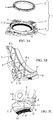
- FIGS 1, 2 and 3A show an angular detection device 1 comprising, on the one hand, a first movable body 2 of generally annular shape, rigidly mounted on a rotating part, for example of the shaft, axle or the like type (not specifically shown), with an axial direction X, and having teeth and / or similar detectable elements 4 distributed in a circumferentially arranged arrangement of said annular body 2 and, secondly, a second fixed body 5 defining a circular opening structure 5 'around and / or opposite the first movable annular body 2.
- This second body 5 carries one or more sensors 5 "capable (s), on the one hand, to individually detect the teeth and / or similar elements 4 of the first movable body 2 during their positioning or passage at a given location and, secondly, to generate a corresponding informative signal.
- the said first and second bodies 2 and 5 delimit between them a passage in form of fent e or circumferential gap (the) 6, possibly with a labyrinthine constitution or baffled (s).
- the first movable body and / or the second fixed body 5 comprises (s) one or more formation (s) 7, 7 ', possibly mutually cooperating, recessed and / or protruding, suitable (s) and intended (s) to generate an air flow FA creating a circumferential dynamic seal at the passage or the gap 6 during the rotation of the rotating part 3, this by cooperation between the two bodies 2 and 5.
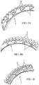
- the second fixed body 5 has a wall circular circular extension 8, surrounding the first annular movable body 2, one or formations (s) 7 'in relief or recessed helical configuration, comprising either a single coil 9 extending over the entire inner periphery of said circular wall 8, ie a plurality of portions of successive turns 9 'distributed on the inner periphery of said wall 8.
- the invention proposes a device 1 incorporating means for creating a dynamic seal between the two bodies 2 and 5, without establishing any contact, without requiring separate additional means, without significant constructive modification and without influencing the function of angular detection.
- the air flow FA is ejected on the side of the device 1 opposite the face facing the shaft portion or axis 3 to be sealed.
- This ejection is radially outward with a more or less inclined angle (between 0 ° and 90 °) with respect to the axial direction X, depending on the conformation of the parts 2 and 5 and the passage 6.
- the second fixed body 5 is a directional deflector, concentrator and / or amplifier for the air flow generated by the rotation of the first annular movable body 2 provided with formations 7 providing air entrainment surfaces, such as blades, fins, blades or the like.
- formations 7 providing air entrainment surfaces, such as blades, fins, blades or the like.
- the second fixed body 5 comprises at least a first wall 8 extending axially surrounding the first movable body annular 2 and at least a second wall 8 'extending radially inwardly from the first outer surrounding wall 8, at least partially facing said first annular movable body 2.
- the second fixed body 5 comprises at least one seal material seal 10 intended to cooperate with the first annular movable body 2 to seal the passage-shaped slot or circumferential gap (the) 6 between the two bodies 2 and 5, preferably its opposite end to its ejection opening of the gas flow FA.
- the seal 10 can be very advantageously mounted on the inner contour of the second radially extending wall 8 'in the form of an annular plate, possibly at the free edge of an axial flange 8 "extending said second wall 8 '.
- the two bodies 2 and 5 can be mounted mutually nested (the upper wing of a C extending between the two wings of the other C ), thus constituting a passage 6 with several baffles.
- the second fixed body 5, with circular opening 5 'cooperating with the first annular movable body 2 defines a circumferential annular groove 11 adapted to channel the air flow FA generated by the rotation of said first annular movable body 2.
- the formation (s) 7 'can (wind) be formed (s) in the outer side wall of this groove 11, in which can be circulated the portion of the annular movable body 2 provided with teeth 4 (section C).
- the bodies 2 and 5 each have respective formations 7 and 7 'cooperating functionally with each other to create the dynamic air flow seal during the rotation of the part 3.
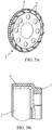
- the formations 7 present on the first annular mobile body 2 consist of teeth 4 aerodynamically shaped to generate, when the rotation of said first body 2, and by cooperation with formations 7 'present on the second fixed body 5, the controlled airflow FA forming a dynamic seal.
- teeth 4 may advantageously be identical with the teeth whose detection by the sensor (s) 5 "makes it possible to determine the position and / or the angular displacement of the rotor 2.
- the first movable annular body 2 is made of sheet metal with at least one radially extending wall, advantageously in the form of an annular plate 8 'and at least one axially extending wall 8, the formations 7 capable of generating an air flow, distributed over its circumference, consisting of vanes, blades or vanes reported on or formed by punctures in at least one of said walls 8, 8 ', in a manner that is not interfering with the teeth or similar detectable elements 4.
- the first movable annular body 2 comprises an armature with at least one radially extending wall 8 ', advantageously in the form of an annular plate, on which the formations 7 able to generate an air flow, distributed over its circumference, and consisting of blades, vanes or vanes, consist of relief structures obtained by overmolding a synthetic material, possibly simultaneously with the teeth or similar detectable elements 4.
- the invention also relates to a sealed casing (not shown) whose wall is traversed by a rotary shaft, a seal or a seal arrangement being mounted at the passage in the wall.
- This casing is characterized in that a device 1 as described above is installed near the outer opening of said passage so as to provide, in addition to the angular position detection function of the shaft 3, also a function dynamic protection against external contaminants for passage.
- the invention also relates to a bearing for a rotary shaft (not shown), comprising a seal or an arrangement of seals and with which is associated an angular detection device for the position and / or angular movement of the rotary shaft, bearing device characterized in that the angular detection device is a device 1 as mentioned and described herein. -above.
Landscapes
- Engineering & Computer Science (AREA)
- General Engineering & Computer Science (AREA)
- Mechanical Engineering (AREA)
- Physics & Mathematics (AREA)
- General Physics & Mathematics (AREA)
- Transmission And Conversion Of Sensor Element Output (AREA)
- Indicating Or Recording The Presence, Absence, Or Direction Of Movement (AREA)
- Sealing Using Fluids, Sealing Without Contact, And Removal Of Oil (AREA)
Applications Claiming Priority (1)
| Application Number | Priority Date | Filing Date | Title |
|---|---|---|---|
| FR1650549A FR3047065A1 (fr) | 2016-01-25 | 2016-01-25 | Dispositif de detection angulaire avec une protection contre les contaminants exterieurs |
Publications (2)
| Publication Number | Publication Date |
|---|---|
| EP3203122A1 true EP3203122A1 (de) | 2017-08-09 |
| EP3203122B1 EP3203122B1 (de) | 2018-03-28 |
Family
ID=55486945
Family Applications (1)
| Application Number | Title | Priority Date | Filing Date |
|---|---|---|---|
| EP17305081.6A Active EP3203122B1 (de) | 2016-01-25 | 2017-01-25 | Vorrichtung zur winkelerfassung mit einem schutz gegen verunreinigungen von aussen |
Country Status (2)
| Country | Link |
|---|---|
| EP (1) | EP3203122B1 (de) |
| FR (1) | FR3047065A1 (de) |
Citations (11)
| Publication number | Priority date | Publication date | Assignee | Title |
|---|---|---|---|---|
| GB1212715A (en) * | 1968-02-14 | 1970-11-18 | Stefa Industri Ab | Shaft sealing ring |
| GB2123498A (en) | 1982-05-28 | 1984-02-01 | Skf Svenska Kullagerfab Ab | Sealing bearing cavities |
| US6305353B1 (en) | 1998-02-27 | 2001-10-23 | Cummins Engine Company | Electronic engine speed and position apparatus for camshaft gear applications |
| US20060091612A1 (en) * | 2003-06-16 | 2006-05-04 | G A Gold Seal Development Ltd | Pressure resistant static and dynamic expeller shaft sealing |
| EP2093574A1 (de) * | 2008-02-19 | 2009-08-26 | Aktiebolaget SKF | Kombinierte Vorrichtung zur Dreherfassung und Abdichtung von Lagern |
| CN202469005U (zh) | 2011-12-09 | 2012-10-03 | 贺晓东 | 迷宫式微动力密封装置 |
| FR2986598A1 (fr) | 2012-02-03 | 2013-08-09 | Freudenberg Carl Kg | Joint d'etancheite |
| EP2739885A1 (de) | 2011-08-03 | 2014-06-11 | Carl Freudenberg KG | Verschluss |
| US20140374993A1 (en) | 2011-12-19 | 2014-12-25 | Aktiebolaget Skf | Pressure Resistant Static and Dynamic Seal Assembly and Method |
| EP2895773A2 (de) | 2012-09-14 | 2015-07-22 | Carl Freudenberg KG | Dichtung, insbesondere für eine unter druck stehende flüssigkeit |
| FR3018575A1 (fr) | 2014-03-12 | 2015-09-18 | Freudenberg Carl Kg | Dispositif d'etancheite double pour arbre rotatif et pompe comportant un tel dispositif |
-
2016
- 2016-01-25 FR FR1650549A patent/FR3047065A1/fr not_active Ceased
-
2017
- 2017-01-25 EP EP17305081.6A patent/EP3203122B1/de active Active
Patent Citations (11)
| Publication number | Priority date | Publication date | Assignee | Title |
|---|---|---|---|---|
| GB1212715A (en) * | 1968-02-14 | 1970-11-18 | Stefa Industri Ab | Shaft sealing ring |
| GB2123498A (en) | 1982-05-28 | 1984-02-01 | Skf Svenska Kullagerfab Ab | Sealing bearing cavities |
| US6305353B1 (en) | 1998-02-27 | 2001-10-23 | Cummins Engine Company | Electronic engine speed and position apparatus for camshaft gear applications |
| US20060091612A1 (en) * | 2003-06-16 | 2006-05-04 | G A Gold Seal Development Ltd | Pressure resistant static and dynamic expeller shaft sealing |
| EP2093574A1 (de) * | 2008-02-19 | 2009-08-26 | Aktiebolaget SKF | Kombinierte Vorrichtung zur Dreherfassung und Abdichtung von Lagern |
| EP2739885A1 (de) | 2011-08-03 | 2014-06-11 | Carl Freudenberg KG | Verschluss |
| CN202469005U (zh) | 2011-12-09 | 2012-10-03 | 贺晓东 | 迷宫式微动力密封装置 |
| US20140374993A1 (en) | 2011-12-19 | 2014-12-25 | Aktiebolaget Skf | Pressure Resistant Static and Dynamic Seal Assembly and Method |
| FR2986598A1 (fr) | 2012-02-03 | 2013-08-09 | Freudenberg Carl Kg | Joint d'etancheite |
| EP2895773A2 (de) | 2012-09-14 | 2015-07-22 | Carl Freudenberg KG | Dichtung, insbesondere für eine unter druck stehende flüssigkeit |
| FR3018575A1 (fr) | 2014-03-12 | 2015-09-18 | Freudenberg Carl Kg | Dispositif d'etancheite double pour arbre rotatif et pompe comportant un tel dispositif |
Also Published As
| Publication number | Publication date |
|---|---|
| FR3047065A1 (fr) | 2017-07-28 |
| EP3203122B1 (de) | 2018-03-28 |
Similar Documents
| Publication | Publication Date | Title |
|---|---|---|
| FR2947217A1 (fr) | Chaine cinematique hybride | |
| EP0726468A1 (de) | Kodiervorrichtung für Geschwindigkeitsmessaufnehmer sowie ein mit einer solchen Vorrichtung versehenes Wälzlager | |
| EP0631072A1 (de) | Dichtung für Drehwelle | |
| EP2801702A1 (de) | Stator-Innenring eines Turbotriebwerks mit Abriebmaterial | |
| FR3062757A1 (fr) | Moteur auto-ventile silencieux, notamment pour un vehicule ferroviaire | |
| WO1997015833A1 (fr) | Dispositif de fixation d'un capteur sur un palier a corps roulants | |
| FR3037117A1 (de) | ||
| EP3153328A1 (de) | Turbineneinsatz für fahrzeugrad | |
| CN105299059A (zh) | 具有保护环的车辆轮毂轴承单元 | |
| EP3414475B1 (de) | Verbesserte dichtungsvorrichtung, insbesondere im hinblick auf eine kontamination durch externe agenten | |
| EP3203122B1 (de) | Vorrichtung zur winkelerfassung mit einem schutz gegen verunreinigungen von aussen | |
| EP1911998B1 (de) | Abdichtungssystem zwischen zwei koaxialen Drehwellen | |
| EP2186705B1 (de) | Instrumentiertes Wälzlager für Schienenfahrzeugsachse und entsprechendes Montageverfahren | |
| FR2909018A1 (fr) | Perfectionnement aux outils d'usinage rotatifs, en particulier de type outils rotatifs coupants. | |
| EP3111116B1 (de) | Reduzierung der leckageflussrate einer bürstendichtung durch flexible geometrische blockierung | |
| FR2927395A3 (fr) | Bague de protection d'un joint d'etancheite dynamique entre une piece fixe et un arbre de transmission d'un groupe motopropulseur d'un vehicule automobile et groupe motopropulseur comportant une telle bague de protection | |
| FR2686032A1 (fr) | Dispositif de pulverisation d'un liquide, notamment d'un combustible liquide dans un bruleur. | |
| WO2018073508A1 (fr) | Motopompe a rotor noye, et procede de fabrication d'une telle motopompe | |
| CA2780407A1 (fr) | Systeme electronique comprenant une structure fixe comportant une enveloppe de protection d'equipements electroniques et une structure mobile par rapport a la structure fixe, la structure mobile comportant une ouverture d'aspiration de l'air | |
| EP2335796B1 (de) | Ölfiltervorrichtung und eine solche Vorrichtung umfassendes Fahrzeug | |
| FR3038028A1 (fr) | Dispositif de galet tendeur | |
| FR2804477A1 (fr) | Dispositif d'evacuation des gaz du carter d'un moteur a combustion interne | |
| FR3036674A1 (fr) | Groupe motoreducteur comprenant une membrane respirante | |
| FR3074837B1 (fr) | Aube de rotor pour une turbomachine | |
| JP7221822B2 (ja) | エンジンのシール構造 |
Legal Events
| Date | Code | Title | Description |
|---|---|---|---|
| PUAI | Public reference made under article 153(3) epc to a published international application that has entered the european phase |
Free format text: ORIGINAL CODE: 0009012 |
|
| STAA | Information on the status of an ep patent application or granted ep patent |
Free format text: STATUS: THE APPLICATION HAS BEEN PUBLISHED |
|
| AK | Designated contracting states |
Kind code of ref document: A1 Designated state(s): AL AT BE BG CH CY CZ DE DK EE ES FI FR GB GR HR HU IE IS IT LI LT LU LV MC MK MT NL NO PL PT RO RS SE SI SK SM TR |
|
| AX | Request for extension of the european patent |
Extension state: BA ME |
|
| STAA | Information on the status of an ep patent application or granted ep patent |
Free format text: STATUS: REQUEST FOR EXAMINATION WAS MADE |
|
| REG | Reference to a national code |
Ref country code: DE Ref legal event code: R079 Ref document number: 602017000026 Country of ref document: DE Free format text: PREVIOUS MAIN CLASS: F16J0015420000 Ipc: G01D0011240000 |
|
| 17P | Request for examination filed |
Effective date: 20170817 |
|
| RBV | Designated contracting states (corrected) |
Designated state(s): AL AT BE BG CH CY CZ DE DK EE ES FI FR GB GR HR HU IE IS IT LI LT LU LV MC MK MT NL NO PL PT RO RS SE SI SK SM TR |
|
| RIC1 | Information provided on ipc code assigned before grant |
Ipc: F16J 15/42 20060101ALI20170907BHEP Ipc: G01D 11/24 20060101AFI20170907BHEP |
|
| GRAP | Despatch of communication of intention to grant a patent |
Free format text: ORIGINAL CODE: EPIDOSNIGR1 |
|
| STAA | Information on the status of an ep patent application or granted ep patent |
Free format text: STATUS: GRANT OF PATENT IS INTENDED |
|
| INTG | Intention to grant announced |
Effective date: 20171102 |
|
| GRAS | Grant fee paid |
Free format text: ORIGINAL CODE: EPIDOSNIGR3 |
|
| GRAA | (expected) grant |
Free format text: ORIGINAL CODE: 0009210 |
|
| STAA | Information on the status of an ep patent application or granted ep patent |
Free format text: STATUS: THE PATENT HAS BEEN GRANTED |
|
| AK | Designated contracting states |
Kind code of ref document: B1 Designated state(s): AL AT BE BG CH CY CZ DE DK EE ES FI FR GB GR HR HU IE IS IT LI LT LU LV MC MK MT NL NO PL PT RO RS SE SI SK SM TR |
|
| REG | Reference to a national code |
Ref country code: GB Ref legal event code: FG4D Free format text: NOT ENGLISH |
|
| REG | Reference to a national code |
Ref country code: CH Ref legal event code: EP |
|
| REG | Reference to a national code |
Ref country code: AT Ref legal event code: REF Ref document number: 983850 Country of ref document: AT Kind code of ref document: T Effective date: 20180415 |
|
| REG | Reference to a national code |
Ref country code: IE Ref legal event code: FG4D Free format text: LANGUAGE OF EP DOCUMENT: FRENCH |
|
| REG | Reference to a national code |
Ref country code: DE Ref legal event code: R096 Ref document number: 602017000026 Country of ref document: DE |
|
| PG25 | Lapsed in a contracting state [announced via postgrant information from national office to epo] |
Ref country code: LT Free format text: LAPSE BECAUSE OF FAILURE TO SUBMIT A TRANSLATION OF THE DESCRIPTION OR TO PAY THE FEE WITHIN THE PRESCRIBED TIME-LIMIT Effective date: 20180328 Ref country code: NO Free format text: LAPSE BECAUSE OF FAILURE TO SUBMIT A TRANSLATION OF THE DESCRIPTION OR TO PAY THE FEE WITHIN THE PRESCRIBED TIME-LIMIT Effective date: 20180628 Ref country code: FI Free format text: LAPSE BECAUSE OF FAILURE TO SUBMIT A TRANSLATION OF THE DESCRIPTION OR TO PAY THE FEE WITHIN THE PRESCRIBED TIME-LIMIT Effective date: 20180328 Ref country code: HR Free format text: LAPSE BECAUSE OF FAILURE TO SUBMIT A TRANSLATION OF THE DESCRIPTION OR TO PAY THE FEE WITHIN THE PRESCRIBED TIME-LIMIT Effective date: 20180328 |
|
| REG | Reference to a national code |
Ref country code: NL Ref legal event code: MP Effective date: 20180328 |
|
| REG | Reference to a national code |
Ref country code: LT Ref legal event code: MG4D |
|
| PG25 | Lapsed in a contracting state [announced via postgrant information from national office to epo] |
Ref country code: GR Free format text: LAPSE BECAUSE OF FAILURE TO SUBMIT A TRANSLATION OF THE DESCRIPTION OR TO PAY THE FEE WITHIN THE PRESCRIBED TIME-LIMIT Effective date: 20180629 Ref country code: BG Free format text: LAPSE BECAUSE OF FAILURE TO SUBMIT A TRANSLATION OF THE DESCRIPTION OR TO PAY THE FEE WITHIN THE PRESCRIBED TIME-LIMIT Effective date: 20180628 Ref country code: RS Free format text: LAPSE BECAUSE OF FAILURE TO SUBMIT A TRANSLATION OF THE DESCRIPTION OR TO PAY THE FEE WITHIN THE PRESCRIBED TIME-LIMIT Effective date: 20180328 Ref country code: SE Free format text: LAPSE BECAUSE OF FAILURE TO SUBMIT A TRANSLATION OF THE DESCRIPTION OR TO PAY THE FEE WITHIN THE PRESCRIBED TIME-LIMIT Effective date: 20180328 Ref country code: LV Free format text: LAPSE BECAUSE OF FAILURE TO SUBMIT A TRANSLATION OF THE DESCRIPTION OR TO PAY THE FEE WITHIN THE PRESCRIBED TIME-LIMIT Effective date: 20180328 |
|
| PG25 | Lapsed in a contracting state [announced via postgrant information from national office to epo] |
Ref country code: MT Free format text: LAPSE BECAUSE OF FAILURE TO SUBMIT A TRANSLATION OF THE DESCRIPTION OR TO PAY THE FEE WITHIN THE PRESCRIBED TIME-LIMIT Effective date: 20180328 |
|
| PG25 | Lapsed in a contracting state [announced via postgrant information from national office to epo] |
Ref country code: RO Free format text: LAPSE BECAUSE OF FAILURE TO SUBMIT A TRANSLATION OF THE DESCRIPTION OR TO PAY THE FEE WITHIN THE PRESCRIBED TIME-LIMIT Effective date: 20180328 Ref country code: ES Free format text: LAPSE BECAUSE OF FAILURE TO SUBMIT A TRANSLATION OF THE DESCRIPTION OR TO PAY THE FEE WITHIN THE PRESCRIBED TIME-LIMIT Effective date: 20180328 Ref country code: NL Free format text: LAPSE BECAUSE OF FAILURE TO SUBMIT A TRANSLATION OF THE DESCRIPTION OR TO PAY THE FEE WITHIN THE PRESCRIBED TIME-LIMIT Effective date: 20180328 Ref country code: AL Free format text: LAPSE BECAUSE OF FAILURE TO SUBMIT A TRANSLATION OF THE DESCRIPTION OR TO PAY THE FEE WITHIN THE PRESCRIBED TIME-LIMIT Effective date: 20180328 Ref country code: PL Free format text: LAPSE BECAUSE OF FAILURE TO SUBMIT A TRANSLATION OF THE DESCRIPTION OR TO PAY THE FEE WITHIN THE PRESCRIBED TIME-LIMIT Effective date: 20180328 Ref country code: EE Free format text: LAPSE BECAUSE OF FAILURE TO SUBMIT A TRANSLATION OF THE DESCRIPTION OR TO PAY THE FEE WITHIN THE PRESCRIBED TIME-LIMIT Effective date: 20180328 |
|
| PG25 | Lapsed in a contracting state [announced via postgrant information from national office to epo] |
Ref country code: SK Free format text: LAPSE BECAUSE OF FAILURE TO SUBMIT A TRANSLATION OF THE DESCRIPTION OR TO PAY THE FEE WITHIN THE PRESCRIBED TIME-LIMIT Effective date: 20180328 Ref country code: CZ Free format text: LAPSE BECAUSE OF FAILURE TO SUBMIT A TRANSLATION OF THE DESCRIPTION OR TO PAY THE FEE WITHIN THE PRESCRIBED TIME-LIMIT Effective date: 20180328 Ref country code: SM Free format text: LAPSE BECAUSE OF FAILURE TO SUBMIT A TRANSLATION OF THE DESCRIPTION OR TO PAY THE FEE WITHIN THE PRESCRIBED TIME-LIMIT Effective date: 20180328 |
|
| REG | Reference to a national code |
Ref country code: AT Ref legal event code: MK05 Ref document number: 983850 Country of ref document: AT Kind code of ref document: T Effective date: 20180328 |
|
| PG25 | Lapsed in a contracting state [announced via postgrant information from national office to epo] |
Ref country code: PT Free format text: LAPSE BECAUSE OF FAILURE TO SUBMIT A TRANSLATION OF THE DESCRIPTION OR TO PAY THE FEE WITHIN THE PRESCRIBED TIME-LIMIT Effective date: 20180730 |
|
| REG | Reference to a national code |
Ref country code: DE Ref legal event code: R097 Ref document number: 602017000026 Country of ref document: DE |
|
| PG25 | Lapsed in a contracting state [announced via postgrant information from national office to epo] |
Ref country code: DK Free format text: LAPSE BECAUSE OF FAILURE TO SUBMIT A TRANSLATION OF THE DESCRIPTION OR TO PAY THE FEE WITHIN THE PRESCRIBED TIME-LIMIT Effective date: 20180328 Ref country code: AT Free format text: LAPSE BECAUSE OF FAILURE TO SUBMIT A TRANSLATION OF THE DESCRIPTION OR TO PAY THE FEE WITHIN THE PRESCRIBED TIME-LIMIT Effective date: 20180328 |
|
| PLBE | No opposition filed within time limit |
Free format text: ORIGINAL CODE: 0009261 |
|
| STAA | Information on the status of an ep patent application or granted ep patent |
Free format text: STATUS: NO OPPOSITION FILED WITHIN TIME LIMIT |
|
| PG25 | Lapsed in a contracting state [announced via postgrant information from national office to epo] |
Ref country code: IT Free format text: LAPSE BECAUSE OF FAILURE TO SUBMIT A TRANSLATION OF THE DESCRIPTION OR TO PAY THE FEE WITHIN THE PRESCRIBED TIME-LIMIT Effective date: 20180328 |
|
| 26N | No opposition filed |
Effective date: 20190103 |
|
| PG25 | Lapsed in a contracting state [announced via postgrant information from national office to epo] |
Ref country code: MC Free format text: LAPSE BECAUSE OF FAILURE TO SUBMIT A TRANSLATION OF THE DESCRIPTION OR TO PAY THE FEE WITHIN THE PRESCRIBED TIME-LIMIT Effective date: 20180328 |
|
| PG25 | Lapsed in a contracting state [announced via postgrant information from national office to epo] |
Ref country code: LU Free format text: LAPSE BECAUSE OF NON-PAYMENT OF DUE FEES Effective date: 20190125 |
|
| REG | Reference to a national code |
Ref country code: BE Ref legal event code: MM Effective date: 20190131 |
|
| REG | Reference to a national code |
Ref country code: IE Ref legal event code: MM4A |
|
| PG25 | Lapsed in a contracting state [announced via postgrant information from national office to epo] |
Ref country code: BE Free format text: LAPSE BECAUSE OF NON-PAYMENT OF DUE FEES Effective date: 20190131 |
|
| PG25 | Lapsed in a contracting state [announced via postgrant information from national office to epo] |
Ref country code: IE Free format text: LAPSE BECAUSE OF NON-PAYMENT OF DUE FEES Effective date: 20190125 |
|
| PG25 | Lapsed in a contracting state [announced via postgrant information from national office to epo] |
Ref country code: TR Free format text: LAPSE BECAUSE OF FAILURE TO SUBMIT A TRANSLATION OF THE DESCRIPTION OR TO PAY THE FEE WITHIN THE PRESCRIBED TIME-LIMIT Effective date: 20180328 |
|
| REG | Reference to a national code |
Ref country code: CH Ref legal event code: PL |
|
| PG25 | Lapsed in a contracting state [announced via postgrant information from national office to epo] |
Ref country code: LI Free format text: LAPSE BECAUSE OF NON-PAYMENT OF DUE FEES Effective date: 20200131 Ref country code: CH Free format text: LAPSE BECAUSE OF NON-PAYMENT OF DUE FEES Effective date: 20200131 |
|
| PG25 | Lapsed in a contracting state [announced via postgrant information from national office to epo] |
Ref country code: CY Free format text: LAPSE BECAUSE OF FAILURE TO SUBMIT A TRANSLATION OF THE DESCRIPTION OR TO PAY THE FEE WITHIN THE PRESCRIBED TIME-LIMIT Effective date: 20180328 |
|
| PG25 | Lapsed in a contracting state [announced via postgrant information from national office to epo] |
Ref country code: IS Free format text: LAPSE BECAUSE OF FAILURE TO SUBMIT A TRANSLATION OF THE DESCRIPTION OR TO PAY THE FEE WITHIN THE PRESCRIBED TIME-LIMIT Effective date: 20180728 |
|
| PG25 | Lapsed in a contracting state [announced via postgrant information from national office to epo] |
Ref country code: HU Free format text: LAPSE BECAUSE OF FAILURE TO SUBMIT A TRANSLATION OF THE DESCRIPTION OR TO PAY THE FEE WITHIN THE PRESCRIBED TIME-LIMIT; INVALID AB INITIO Effective date: 20170125 |
|
| GBPC | Gb: european patent ceased through non-payment of renewal fee |
Effective date: 20210125 |
|
| PG25 | Lapsed in a contracting state [announced via postgrant information from national office to epo] |
Ref country code: SI Free format text: LAPSE BECAUSE OF FAILURE TO SUBMIT A TRANSLATION OF THE DESCRIPTION OR TO PAY THE FEE WITHIN THE PRESCRIBED TIME-LIMIT Effective date: 20180328 |
|
| PG25 | Lapsed in a contracting state [announced via postgrant information from national office to epo] |
Ref country code: GB Free format text: LAPSE BECAUSE OF NON-PAYMENT OF DUE FEES Effective date: 20210125 |
|
| PG25 | Lapsed in a contracting state [announced via postgrant information from national office to epo] |
Ref country code: MK Free format text: LAPSE BECAUSE OF FAILURE TO SUBMIT A TRANSLATION OF THE DESCRIPTION OR TO PAY THE FEE WITHIN THE PRESCRIBED TIME-LIMIT Effective date: 20180328 |
|
| PGFP | Annual fee paid to national office [announced via postgrant information from national office to epo] |
Ref country code: DE Payment date: 20260127 Year of fee payment: 10 |
|
| PGFP | Annual fee paid to national office [announced via postgrant information from national office to epo] |
Ref country code: FR Payment date: 20260126 Year of fee payment: 10 |