EP3203178A1 - Fusil comprenant un levier basculant d'armement avec axe de rotation derrière la gâchette - Google Patents
Fusil comprenant un levier basculant d'armement avec axe de rotation derrière la gâchette Download PDFInfo
- Publication number
- EP3203178A1 EP3203178A1 EP17155025.4A EP17155025A EP3203178A1 EP 3203178 A1 EP3203178 A1 EP 3203178A1 EP 17155025 A EP17155025 A EP 17155025A EP 3203178 A1 EP3203178 A1 EP 3203178A1
- Authority
- EP
- European Patent Office
- Prior art keywords
- lever
- gun
- trigger
- action
- lever arm
- Prior art date
- Legal status (The legal status is an assumption and is not a legal conclusion. Google has not performed a legal analysis and makes no representation as to the accuracy of the status listed.)
- Withdrawn
Links
- 230000009471 action Effects 0.000 title claims abstract description 23
- 230000007246 mechanism Effects 0.000 claims abstract description 48
- 230000033001 locomotion Effects 0.000 claims abstract description 31
- 238000010304 firing Methods 0.000 claims abstract description 11
- 230000005540 biological transmission Effects 0.000 claims abstract description 6
- 230000008901 benefit Effects 0.000 description 10
- 210000003811 finger Anatomy 0.000 description 5
- 230000004075 alteration Effects 0.000 description 2
- 238000005452 bending Methods 0.000 description 2
- 230000007812 deficiency Effects 0.000 description 1
- 239000002360 explosive Substances 0.000 description 1
- 210000000245 forearm Anatomy 0.000 description 1
- 230000006872 improvement Effects 0.000 description 1
- 238000012423 maintenance Methods 0.000 description 1
- 210000003813 thumb Anatomy 0.000 description 1
- 238000012559 user support system Methods 0.000 description 1
Images


Classifications
-
- F—MECHANICAL ENGINEERING; LIGHTING; HEATING; WEAPONS; BLASTING
- F41—WEAPONS
- F41C—SMALLARMS, e.g. PISTOLS, RIFLES; ACCESSORIES THEREFOR
- F41C7/00—Shoulder-fired smallarms, e.g. rifles, carbines, shotguns
- F41C7/06—Lever-action guns, i.e. guns having a rocking lever for loading or cocking
-
- F—MECHANICAL ENGINEERING; LIGHTING; HEATING; WEAPONS; BLASTING
- F41—WEAPONS
- F41A—FUNCTIONAL FEATURES OR DETAILS COMMON TO BOTH SMALLARMS AND ORDNANCE, e.g. CANNONS; MOUNTINGS FOR SMALLARMS OR ORDNANCE
- F41A19/00—Firing or trigger mechanisms; Cocking mechanisms
- F41A19/06—Mechanical firing mechanisms, e.g. counterrecoil firing, recoil actuated firing mechanisms
- F41A19/11—Trigger guards; Trigger-guard mountings
-
- F—MECHANICAL ENGINEERING; LIGHTING; HEATING; WEAPONS; BLASTING
- F41—WEAPONS
- F41A—FUNCTIONAL FEATURES OR DETAILS COMMON TO BOTH SMALLARMS AND ORDNANCE, e.g. CANNONS; MOUNTINGS FOR SMALLARMS OR ORDNANCE
- F41A3/00—Breech mechanisms, e.g. locks
- F41A3/12—Bolt action, i.e. the main breech opening movement being parallel to the barrel axis
-
- F—MECHANICAL ENGINEERING; LIGHTING; HEATING; WEAPONS; BLASTING
- F41—WEAPONS
- F41A—FUNCTIONAL FEATURES OR DETAILS COMMON TO BOTH SMALLARMS AND ORDNANCE, e.g. CANNONS; MOUNTINGS FOR SMALLARMS OR ORDNANCE
- F41A3/00—Breech mechanisms, e.g. locks
- F41A3/64—Mounting of breech-blocks; Accessories for breech-blocks or breech-block mountings
- F41A3/66—Breech housings or frames; Receivers
-
- F—MECHANICAL ENGINEERING; LIGHTING; HEATING; WEAPONS; BLASTING
- F41—WEAPONS
- F41A—FUNCTIONAL FEATURES OR DETAILS COMMON TO BOTH SMALLARMS AND ORDNANCE, e.g. CANNONS; MOUNTINGS FOR SMALLARMS OR ORDNANCE
- F41A3/00—Breech mechanisms, e.g. locks
- F41A3/64—Mounting of breech-blocks; Accessories for breech-blocks or breech-block mountings
- F41A3/72—Operating handles or levers; Mounting thereof in breech-blocks or bolts
-
- F—MECHANICAL ENGINEERING; LIGHTING; HEATING; WEAPONS; BLASTING
- F41—WEAPONS
- F41A—FUNCTIONAL FEATURES OR DETAILS COMMON TO BOTH SMALLARMS AND ORDNANCE, e.g. CANNONS; MOUNTINGS FOR SMALLARMS OR ORDNANCE
- F41A9/00—Feeding or loading of ammunition; Magazines; Guiding means for the extracting of cartridges
- F41A9/61—Magazines
- F41A9/64—Magazines for unbelted ammunition
- F41A9/72—Tubular magazines, i.e. magazines containing the ammunition in lengthwise tandem sequence
Definitions
- the invention relates to single barrel magazine-fed, repeating, lever action firearms and lever action non-firearms.
- the invention particularly relates to lever guns providing quicker use by means of their levers being centred behind the trigger, and thus eliminating additional requirements in gun design, as well as performing force transmission without loss and providing advantage of field by means of the lever arm consisting of a plurality of parts connected to each other via movable hinges.
- lever action rifles are considered to be under the group of firearms (explosive weapons) and their mechanisms are set and operated by moving their levers around a fixed hinge point by means of pushing with manual force.
- US patent No. US3287842 entitled: "Knockdown repeating lever action rifle”
- the divider point is found in front of the trigger and the opening movement is required to be made with a wider angle and at a longer distance.
- the finger pulling the trigger gets away from the trigger each time, and it is required to be re-adjusted according to the trigger when closed.
- the target may be lost for the next cartridge shot due to the distance of opening and closing.
- Another disadvantage is the requirement of complete re-design of the trigger guard and the mechanism for this purpose. Therefore, alteration of size may be required for appropriate operation of the mechanism parts, and thus a cost increasing factor occurs.
- the invention relates to lever guns, which meet the above said requirements, eliminates all of the drawbacks, and brings some additional advantages.
- the main purpose of the lever gun according to the invention is to narrow down the lever angle and thus reduce the operating distance by means of centring the divider point of the lever behind the trigger, preferably on the trigger guard.
- the finger pulling the trigger is not removed from the trigger/trigger guard and thus the need for reaching the trigger again for pulling the trigger next time is eliminated.
- the time period between the first and second firing is reduced.
- the rate of hitting the target from the same point without moving the rifle is increased.
- loss of target is avoided due to short opening and closing distance.
- Another purpose of the invention is to provide more flexible bending and operating angles by means of the lever arm, which transmits the lever motion to the mechanism, being formed of at least two parts that are connected to each other via movable hinges, and thus ensure that the direction of the movement provided to the mechanism by the lever is only in forward and backward directions. In this way, since movements in upward and downward directions are prevented, a system that can be opened and closed in an easier manner with less amount of applied force is presented and a wider angular motion can be provided. Accordingly, the size of the housing where the lever arm is connected can be reduced.
- Another purpose of the invention is to minimize the friction forces that make movement harder, by means of forming the movable hinges between the lever arm parts and the divider component at which the lever motion is centred by male and female components. Besides reduced friction, the possibility of loosening of the hinges due to movement and rotation is also reduced. The maintenance and replacement costs are reduced. Moreover, advantage is obtained in demounting of the system.
- Another purpose of the invention is to provide freedom of connecting from different points to the mechanism such as from upper or lower points, by means of forming some part of the lever arm connected to the mechanism in an angular manner.
- the lever gun developed comprises a receiver bearing the whole structure and all other components, a mechanism performing the cocking and locking functions, a trigger mechanism performing the firing function, a barrel, through which the fired ammunition is guided towards the target, a magazine storing the ammunition, a lever driving and thus cocking/setting said mechanism, a divider component positioned at the rear side of said trigger mechanism that does not face the barrel, and at which the lever is centred in order to perform rotating motion, and at least two lever arms performing transmission of motion between the lever and the mechanism, and connected to each other via movable hinges.
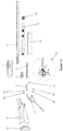
- the lever gun (9) shown in a general state in Figure 1 and a demounted state in Figure 2 basically comprises: a receiver (1) bearing the whole structure and all other components, a mechanism (4) performing the cocking and locking functions, a trigger mechanism (13) performing the firing function, a barrel (14), through which the fired ammunition is guided towards the target, a magazine (16) storing the ammunition and a lever (2) driving and thus cocking/setting said mechanism (4).
- the lever gun (9) comprises: a divider component (8) positioned at the rear side of said trigger mechanism (13) that does not face the barrel (14), and at which the lever (2) is centred in order to perform rotating motion; and at least two lever arms (3) performing transmission of motion between the lever (2) and the mechanism (4), and connected to each other via movable hinges (6).
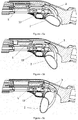
- FIG 3 a close-up sectional view of the lever gun (9) is shown.
- the lever housing (7) formed within the receiver (1) ensures positioning and movement of the lever arm (3) within the receiver (1).
- the lever arm (3) being formed of a plurality of parts enables keeping the volume of the lever housing (7) at the minimum level and provides advantages in design.
- the connection of the lever arm (3) with the action bar (5) transmitting its motion to the mechanism (4) is made by means of a rotating action bar connection (10).
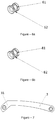
- Figure 7 is the close-up view of the lever arm (3) connected to the action bar (5) found in the lever gun (9).
- a lever arm extension (31) is formed by forming a part of the lever arm (3) in an angular manner to the lever arm (3) itself. In this way, the lever arm (3) can be connected to the mechanism (4) and the other components found on the lever gun (9) through different angles in order to provide advantages in design.
- Figure 6a shows a close-up view of the hinge (6).
- the structure of the hinge (6) formed of a male hinge bolt (61) and a female hinge bolt (62) provides advantages by means of reducing the friction force of the rotating motion during the movement of the lever arms (3).
- Figure 6b shows a close-up view of the divider component (8).
- the structure of the divider component (8) formed of a male divider component (81) and a female divider component (82) provides advantages by means of reducing the friction force of the rotating motion during the movement of the divider (2).
- the lever gun (9) is a single barrel (14) and magazine-fed (16) repeating shotgun. Therefore, after each firing or before firing, the mechanism (4) is required to be set via the lever (2).
- the lever gun (9) becomes ready for fire after the mechanism (4) is set. All of the components are embedded within the receiver (1).
- the magazine cap (17) fixes the barrel (14) and the forend (15). While the lever (2) and the lever arm (3) can be connected to each other in a fixed manner as shown in Figure 4 , they can also be connected in a movable manner by means of a hinge (6) providing connection of the lever arms (3) with each other.
- the lever (2) and the trigger mechanism (13) are connected to each other via a movable divider component (8) from the rear part of the lever gun (9).
- a movable action bar connection (10) is used for connecting the lever arm (3) with the action bar (5).
- the lever (2) is pulled downward with the three fingers next to the index finger as shown in Figures 5a, 5b, and 5c .
- the mechanism (4) and the action bar (5) connected to the lever arm (3) come backward and make the trigger mechanism (13) ready for firing.
- the mechanism (4) is pulled upward until it contacts the barrel (14) group and thus locking operation is fulfilled.
- the lever gun (9) is set and made ready for firing.
- the ammunition required for firing is found in the magazine (16).
- the ammunition is taken from the magazine (16) and given into the barrel (14) automatically via the trigger mechanism (13) in each setting operation.
- the user supports the stock (11) and the recoil pad (12) of the lever gun (9) with his/her shoulder and tightly grasps the forend (15). In this way, the lever gun (9) can be held with more support.
- the ammunition is fired towards the target through the barrel (14) by means of driving the trigger mechanism (13). After firing, each time, the movement of the lever (2) around the divider component (8) is repeated.
Landscapes
- Engineering & Computer Science (AREA)
- General Engineering & Computer Science (AREA)
- Toys (AREA)
- Spray Control Apparatus (AREA)
Applications Claiming Priority (1)
| Application Number | Priority Date | Filing Date | Title |
|---|---|---|---|
| TR2016/01620A TR201601620A2 (tr) | 2016-02-08 | 2016-02-08 | Levyeli silahlarda yenilik |
Publications (1)
| Publication Number | Publication Date |
|---|---|
| EP3203178A1 true EP3203178A1 (fr) | 2017-08-09 |
Family
ID=57995071
Family Applications (1)
| Application Number | Title | Priority Date | Filing Date |
|---|---|---|---|
| EP17155025.4A Withdrawn EP3203178A1 (fr) | 2016-02-08 | 2017-02-07 | Fusil comprenant un levier basculant d'armement avec axe de rotation derrière la gâchette |
Country Status (4)
| Country | Link |
|---|---|
| US (1) | US20170227318A1 (fr) |
| EP (1) | EP3203178A1 (fr) |
| AU (1) | AU2016201404A1 (fr) |
| TR (1) | TR201601620A2 (fr) |
Cited By (3)
| Publication number | Priority date | Publication date | Assignee | Title |
|---|---|---|---|---|
| WO2023146956A1 (fr) * | 2022-01-28 | 2023-08-03 | Bond Arms Inc. | Arme à feu à levier |
| US11988479B1 (en) | 2023-09-13 | 2024-05-21 | Ares Defense Systems, Inc. | Bolt carrier movement mechanism providing primary extraction force multiplication, firearms comprising same, kits for constructing firearms comprising same, and bolt carrier groups for enabling same |
| US12152844B2 (en) | 2022-09-09 | 2024-11-26 | Ares Defense Systems, Inc. | Lever-action firearm and kit for constructing the same |
Families Citing this family (5)
| Publication number | Priority date | Publication date | Assignee | Title |
|---|---|---|---|---|
| USD890877S1 (en) * | 2019-03-06 | 2020-07-21 | Benelli Armi S.P.A. | Shotgun receiver |
| USD969257S1 (en) * | 2020-02-19 | 2022-11-08 | Moab Ventures, LLC | Air gun |
| WO2022091143A1 (fr) * | 2020-10-29 | 2022-05-05 | Pedersoli Davide & C.S.N.C. Di Pedersoli Pierangelo E Silvana | Levier d'armement, en particulier pour armes à feu destinées à être utilisées dans la chasse du type à répétition à levier |
| US12516898B2 (en) * | 2022-09-13 | 2026-01-06 | Henry RAC Holding Corp | Firearm four-bar linkage and slider-crank mechanisms and related techniques |
| USD1060582S1 (en) * | 2023-07-26 | 2025-02-04 | ERRESSE S.r.l. | Rifle |
Citations (3)
| Publication number | Priority date | Publication date | Assignee | Title |
|---|---|---|---|---|
| US1552347A (en) * | 1924-06-19 | 1925-09-01 | William H Rose | Repeating-rifle bolt action |
| US3287842A (en) | 1964-09-23 | 1966-11-29 | Denhoff Alice | Knockdown repeating lever action rifle |
| US5758444A (en) * | 1996-01-04 | 1998-06-02 | Sturm, Ruger & Company, Inc. | Hammer cocking bolt locking system for lever operating firearm |
-
2016
- 2016-02-08 TR TR2016/01620A patent/TR201601620A2/tr unknown
- 2016-03-03 AU AU2016201404A patent/AU2016201404A1/en not_active Abandoned
-
2017
- 2017-02-07 EP EP17155025.4A patent/EP3203178A1/fr not_active Withdrawn
- 2017-02-08 US US15/427,220 patent/US20170227318A1/en not_active Abandoned
Patent Citations (3)
| Publication number | Priority date | Publication date | Assignee | Title |
|---|---|---|---|---|
| US1552347A (en) * | 1924-06-19 | 1925-09-01 | William H Rose | Repeating-rifle bolt action |
| US3287842A (en) | 1964-09-23 | 1966-11-29 | Denhoff Alice | Knockdown repeating lever action rifle |
| US5758444A (en) * | 1996-01-04 | 1998-06-02 | Sturm, Ruger & Company, Inc. | Hammer cocking bolt locking system for lever operating firearm |
Cited By (4)
| Publication number | Priority date | Publication date | Assignee | Title |
|---|---|---|---|---|
| WO2023146956A1 (fr) * | 2022-01-28 | 2023-08-03 | Bond Arms Inc. | Arme à feu à levier |
| US11988480B2 (en) | 2022-01-28 | 2024-05-21 | Bond Arms Inc. | Lever action firearm |
| US12152844B2 (en) | 2022-09-09 | 2024-11-26 | Ares Defense Systems, Inc. | Lever-action firearm and kit for constructing the same |
| US11988479B1 (en) | 2023-09-13 | 2024-05-21 | Ares Defense Systems, Inc. | Bolt carrier movement mechanism providing primary extraction force multiplication, firearms comprising same, kits for constructing firearms comprising same, and bolt carrier groups for enabling same |
Also Published As
| Publication number | Publication date |
|---|---|
| US20170227318A1 (en) | 2017-08-10 |
| TR201601620A2 (tr) | 2016-06-21 |
| AU2016201404A1 (en) | 2017-08-24 |
Similar Documents
| Publication | Publication Date | Title |
|---|---|---|
| EP3203178A1 (fr) | Fusil comprenant un levier basculant d'armement avec axe de rotation derrière la gâchette | |
| EP3129739B1 (fr) | Système de commande de tir pour armes à feu | |
| US9964370B2 (en) | Ambidextrously Operable Firearm Receiver Assembly | |
| US2685754A (en) | Breech-loading magazine firearm | |
| CN102245997B (zh) | 具有用于控制反冲和枪口上跳的新型机构的延迟反冲枪械 | |
| US9915485B2 (en) | Semi-automatic pistol | |
| US9714804B2 (en) | Firearm with safe axis firing pin and center aligned barrel | |
| US10126086B2 (en) | Ambidextrous safety for a firearm | |
| EP2525183A1 (fr) | Pistolet à double barillet et magasin à deux rangées | |
| US9816771B2 (en) | Thumb-operable firearm | |
| US20170241729A1 (en) | Bolt Catch for a Rifle | |
| US8997390B1 (en) | Trigger mechanism with cam surface sear | |
| RS56456B1 (sr) | Automatsko oružje sa pomoćnim okidačem u sklopivom kundaku što omogućava da se iz oružja puca u bul pap konfiguraciji | |
| US3158064A (en) | Firearm with a pivotable barrel having a spherical hump engaging a slide member | |
| US10465999B2 (en) | Handgun with forward assist | |
| US12044492B2 (en) | Magazine latch | |
| US20130104435A1 (en) | Roller style firearm trigger | |
| EP3446061B1 (fr) | Arme de poing ayant un dispositif de verrouillage | |
| US10436531B2 (en) | Recoil apparatus for firearms | |
| US20040159033A1 (en) | Semiautomatic handgun | |
| WO2019245494A2 (fr) | Ensemble lance-grenade modulaire | |
| US20220065577A1 (en) | Trigger device for a buttstock loader | |
| US10852082B1 (en) | Backward swept magazine for pistol | |
| RU2814289C2 (ru) | Пистолет | |
| US20170089665A1 (en) | Palm pistol |
Legal Events
| Date | Code | Title | Description |
|---|---|---|---|
| PUAI | Public reference made under article 153(3) epc to a published international application that has entered the european phase |
Free format text: ORIGINAL CODE: 0009012 |
|
| AK | Designated contracting states |
Kind code of ref document: A1 Designated state(s): AL AT BE BG CH CY CZ DE DK EE ES FI FR GB GR HR HU IE IS IT LI LT LU LV MC MK MT NL NO PL PT RO RS SE SI SK SM TR |
|
| AX | Request for extension of the european patent |
Extension state: BA ME |
|
| TPAC | Observations filed by third parties |
Free format text: ORIGINAL CODE: EPIDOSNTIPA |
|
| STAA | Information on the status of an ep patent application or granted ep patent |
Free format text: STATUS: THE APPLICATION IS DEEMED TO BE WITHDRAWN |
|
| 18D | Application deemed to be withdrawn |
Effective date: 20180210 |