EP3203182A1 - Handschuhe mit mess-, abtastung- und anzeigefähigkeiten - Google Patents
Handschuhe mit mess-, abtastung- und anzeigefähigkeiten Download PDFInfo
- Publication number
- EP3203182A1 EP3203182A1 EP17162973.6A EP17162973A EP3203182A1 EP 3203182 A1 EP3203182 A1 EP 3203182A1 EP 17162973 A EP17162973 A EP 17162973A EP 3203182 A1 EP3203182 A1 EP 3203182A1
- Authority
- EP
- European Patent Office
- Prior art keywords
- glove
- user
- gloves
- attached
- wireless communication
- Prior art date
- Legal status (The legal status is an assumption and is not a legal conclusion. Google has not performed a legal analysis and makes no representation as to the accuracy of the status listed.)
- Granted
Links
Images


Classifications
-
- G—PHYSICS
- G01—MEASURING; TESTING
- G01B—MEASURING LENGTH, THICKNESS OR SIMILAR LINEAR DIMENSIONS; MEASURING ANGLES; MEASURING AREAS; MEASURING IRREGULARITIES OF SURFACES OR CONTOURS
- G01B21/00—Measuring arrangements or details thereof, where the measuring technique is not covered by the other groups of this subclass, unspecified or not relevant
- G01B21/02—Measuring arrangements or details thereof, where the measuring technique is not covered by the other groups of this subclass, unspecified or not relevant for measuring length, width, or thickness
-
- G—PHYSICS
- G01—MEASURING; TESTING
- G01B—MEASURING LENGTH, THICKNESS OR SIMILAR LINEAR DIMENSIONS; MEASURING ANGLES; MEASURING AREAS; MEASURING IRREGULARITIES OF SURFACES OR CONTOURS
- G01B11/00—Measuring arrangements characterised by the use of optical techniques
- G01B11/02—Measuring arrangements characterised by the use of optical techniques for measuring length, width or thickness
-
- G—PHYSICS
- G01—MEASURING; TESTING
- G01B—MEASURING LENGTH, THICKNESS OR SIMILAR LINEAR DIMENSIONS; MEASURING ANGLES; MEASURING AREAS; MEASURING IRREGULARITIES OF SURFACES OR CONTOURS
- G01B11/00—Measuring arrangements characterised by the use of optical techniques
- G01B11/14—Measuring arrangements characterised by the use of optical techniques for measuring distance or clearance between spaced objects or spaced apertures
-
- G—PHYSICS
- G01—MEASURING; TESTING
- G01B—MEASURING LENGTH, THICKNESS OR SIMILAR LINEAR DIMENSIONS; MEASURING ANGLES; MEASURING AREAS; MEASURING IRREGULARITIES OF SURFACES OR CONTOURS
- G01B21/00—Measuring arrangements or details thereof, where the measuring technique is not covered by the other groups of this subclass, unspecified or not relevant
- G01B21/16—Measuring arrangements or details thereof, where the measuring technique is not covered by the other groups of this subclass, unspecified or not relevant for measuring distance of clearance between spaced objects
-
- G—PHYSICS
- G01—MEASURING; TESTING
- G01B—MEASURING LENGTH, THICKNESS OR SIMILAR LINEAR DIMENSIONS; MEASURING ANGLES; MEASURING AREAS; MEASURING IRREGULARITIES OF SURFACES OR CONTOURS
- G01B7/00—Measuring arrangements characterised by the use of electric or magnetic techniques
- G01B7/02—Measuring arrangements characterised by the use of electric or magnetic techniques for measuring length, width or thickness
-
- G—PHYSICS
- G01—MEASURING; TESTING
- G01B—MEASURING LENGTH, THICKNESS OR SIMILAR LINEAR DIMENSIONS; MEASURING ANGLES; MEASURING AREAS; MEASURING IRREGULARITIES OF SURFACES OR CONTOURS
- G01B7/00—Measuring arrangements characterised by the use of electric or magnetic techniques
- G01B7/14—Measuring arrangements characterised by the use of electric or magnetic techniques for measuring distance or clearance between spaced objects or spaced apertures
Definitions
- the present invention relates to logistics and more particularly relates to incorporating logistics tools into a single unit.
- the practice of logistics may be defined as the management of objects as they are moved throughout a system.
- determining the size of a package may include using a tape measure, ruler, or yardstick to measure length, width, and height of the package.
- a basic scale can be used to measure weight.
- a barcode scanner is used to scan barcodes printed on packages.
- the present invention embraces a measuring apparatus comprising a right-handed glove configured to be worn on the right hand of a user and a left-handed glove configured to be worn on the left hand of the user.
- the measuring apparatus also includes a first wireless communication device attached to the right-handed glove and a second wireless communication device attached to the left-handed glove.
- a calculating device is also part of the measuring apparatus.
- the first and second wireless communication devices are configured to wirelessly communicate time-based signals with each other.
- the calculating device utilizes the time-based signals to determine a first dimension of an object.
- a measuring apparatus comprising a pair of gloves.
- the measuring apparatus also comprises means, attached to the pair of gloves, for determining a first dimension of an object.
- the measuring apparatus includes means, attached to the pair of gloves, for measuring the weight of the object.
- the present invention embraces devices for simplifying multiple physical tasks involved in the field of logistics. For example, a person working in a facility that measures, weighs, and tracks packages may use several types of tools for performing these functions. Embodiments for incorporating logistics tools into a single unit, such as a pair of gloves, are discussed in the present disclosure.
- FIG. 1A illustrates a view of a back side of a pair of gloves 10, which includes a right-handed glove 12 and a left-handed glove 14.
- FIG. 1B illustrates a view of a palm side of the pair of gloves 10.
- the right-handed glove 12 is configured to be worn on the right hand of a user and the left-handed glove 14 is configured to be worn on the left hand of the user.
- the right-handed glove 12 includes right finger portions 16R, right thumb portion 18R, and right hand portion 20R.
- the left-handed glove 14 includes left finger portions 16L, left thumb portion 18L, and left hand portion 20L.
- the pair of gloves 10 further includes devices that are attached in any suitable manner to different portions of the gloves 12, 14. As shown in FIG. 1A , a display device 22 is attached to the back of the left hand portion 20L of the left-handed glove 14. Also, a scanner 24 is attached to the back of one of the right finger portions 16R of the right-handed glove 12. FIG. 1A also shows touch pads 26 attached to finger portions 16R, 16L and thumb portions 18R, 18L of the pair of gloves 10.
- FIG. 1B As shown in FIG. 1B , force sensors 28 are attached on the palm side of the finger portions 16R, 16L of the respective gloves 12, 14.
- FIG. 1B also shows wireless communication devices 30 attached on the palm side of the hand portions 20R, 20L of the respective gloves 12, 14.
- the display device 22 is configured to display data related to measured parameters and information related to an object of which the pair of gloves 10 is intended to analyze.
- the object may be a shipping package.
- the pair of gloves 10 is configured to measure the length, width, and height of the object, as explained in more detail below. Also, the pair of gloves 10 can measure the mass (or weight) of the object. The measured dimensions and/or weight can be displayed in any suitable manner on the display device 22 using any suitable units of measure.
- the display device 22 may include an LED screen, LCD screen, or other suitable type of display screen for displaying information to the user. Also, the display device 22 may comprise a material that includes a sufficient level of flexibility to allow the user's hand to bend during normal use without adversely affecting the screen.
- the display device 22 may be configured to allow interaction with the user.
- the display device 22 may be configured to receive input from the user as well as provide output to the user.
- the display device 22 may display input buttons that the user can press to enter a selection.
- the display device 22 can also show a prompt to the user requesting input from the user.
- the display device 22 can indicate when a measurement has been successfully obtained or indicate when an error has occurred, etc.
- the display device 22 may be combined with other output devices, such as audio devices for providing a beeping, buzzing, or other type of audio signal to the user to indicate certain conditions.
- the display device 22 is shown attached to the back side of the hand portion 20L of the left-handed glove 14.
- the left-handed glove 14 may include multiple display devices.
- the display device 16 or multiple display devices may instead be configured on the back of the hand portion 20R of the right-handed glove 12.
- multiple display devices may be configured on the hand portions 20R, 20L of both the right-handed glove 12 and left-handed glove 14.
- the scanner 24 is attached to the back of a finger portion 16R of the right-handed glove 12. As shown, the scanner 18 is attached to the index finger of the finger portions 16R of the right-handed glove 12, but in other embodiments, it may be attached to any finger portion 16R of the glove 12. The scanner 24 is shown as being attached on the finger portion 16R at the knuckle located nearest to the hand portion 20R. According to various embodiments, the scanner 24 may be attached to any knuckle portion, any finger of either glove 12, 14, and according to still other embodiments, may be configured as multiple scanners attached to any knuckle portions of any fingers of either glove 12, 14 of the pair of gloves 10. Furthermore, the scanner 24 may be configured on a fingertip of one of the finger portions 16R, 16L to allow a user to point a particular finger at an optical code being scanned.
- the scanner 24 may be configured to scan a code or image on the object.
- the code may be a one-dimensional barcode, two-dimensional code (e.g., QR code), or other suitable type of optical code.
- the scanner 24 may include one or more light sensors, laser scanning elements, etc.
- the code may be a Radio Frequency Identification (RFID) tag or other wireless transmission tag that the scanner 24 can sense or detect in order to determine an identification of the object.
- RFID tag or other types of tags which may be passive or active type devices, may be placed anywhere on or in the object.
- the touch pads 26 may be located on one or both of the gloves 12, 14, and may be configured in pairs or individually. For example, when configured in pairs, the touch pads 26 may respond when the pair is touched together. In this sense, the touch pads 26 may be conductive elements used for completing a circuit. As individual components, the touch pads 26 may be touch sensitive elements that respond when touched with a predetermined amount of force by any element.
- the touch pads 26 are configured to receive input from the user.
- the input may simply be a binary input, such as on or off input, and may be used to trigger an operation of one of the devices attached to the gloves 12, 14. For instance, if the user touches a pair of touch pads 26 together, such as by pressing the thumb against the side of the index finger, the connection of the touch pads 26 may be sensed and a trigger signal may be sent to one of the other devices (e.g., the scanner 24) of the gloves 12, 14 to initiate a certain operation (e.g., a scanning operation).
- a trigger signal may be sent to one of the other devices (e.g., the scanner 24) of the gloves 12, 14 to initiate a certain operation (e.g., a scanning operation).
- the touch pads 26 may also be configured to control the images and/or information displayed on the display device 22. Also, the touch pads 26 can be used to control when a measurement of the object is obtained. For example, when used in conjunction with the force sensors 28, the touch pads 26 can initiate when the force sensors 28 are in place to properly weight the object. Also, when the wireless communication device 30 are in the proper locations, as described in more detail below, the touch pads 26 can initiate when a dimension of the object is measured.
- the force sensors 28 are located on the palm sides of the finger portions 16R, 16L of the gloves 12, 14. As shown, two force sensors 28 are attached to each of the finger portions 16R, 16L, but in other embodiments, one force sensor 28 or any number of force sensors 28 may be attached to each finger portion 16R, 16L. In some embodiments, one or more force sensors 28 may be located on any finger portions 16R, 16L, any thumb portions 18R, 18L, and/or any hand portions 20R, 20L, preferably on the palm side of the gloves 12, 14. The force sensors 28 may be positioned on an outside surface of the material of the gloves 12, 14 and/or may be embedded in the material of the gloves 12, 14.
- the force sensors 28 may be configured to measure force applied thereto. The measured forces from all the force sensors 28 can be added together to obtain an accumulated force, which is indicative of the weight of the object.
- the user may hold the object (e.g., a shipping package) such that the fingers or finger tips are under the object and are configured to support all the weight of the object. When triggered, the forces are sensed and a weight can be measured.
- Each one of the pair of gloves also includes a wireless communication device 30.
- the wireless communication devices 30 are configured to communication with each other using any suitable type of wireless communication protocol.
- the wireless communication devices 30 may be configured to transmit and receive signals in any suitable frequency range.
- the wireless communication devices 30 may include infrared transmission.
- the wireless communication devices 30 may utilize various radio frequency ranges depending on the various signal transmission protocols.
- the pair of wireless communication devices 30 may be used to determine a distance or displacement between them.
- a first wireless communication device 30 may count the time starting from a first time when a transmission signal is first transmitted toward the second wireless communication device 30 to a second time when the first wireless communication device 30 receives a return signal back from the second wireless communication device 30.
- the second wireless communication device 30 may respond with the return signal either immediately or after a known processing delay.
- the total of the forward and return transmission times is divided by two to get the transmission time from one wireless communication device 30 to the other. This calculated time is then used to determine distance, which corresponds to an outside dimension (e.g., width) of the object.
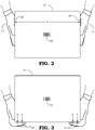
- FIG. 2 illustrates the pair of gloves 10 in use for determining a dimension as explained briefly above.
- the measured dimension is a distance "d" from one end of an object 34 to the other.
- the object 34 is a package or box for which the size and weight thereof is determined.
- the user places the palms of the gloves 12, 14 on opposite sides of the object 34 such that the wireless transmission devices 30 are substantially aligned with each other.
- the dimension e.g., width
- the user may wish to measure the width, length, and height of a rectangular box. For other shapes, such as cylindrical tubes, the user may measure other dimensions, such as length and diameter.
- a volume can be calculated, which may be used to determine shipping costs.
- FIG. 3 illustrates the pair of gloves 10 in use for determining the weight of the object 34.
- the user while wearing the pair of gloves 10, places his or her fingertips underneath the object 34 to support the weight of the object 34.
- the force sensors 28 will be interposed between the user's fingertips and the object 34 and therefore receive the force applied therebetween.
- Forces f 1 , f 2 , f 3 , and f 4 represent each of the groups of forces applied to parts of the finger portions 16R, 16L corresponding to various bones in the user's hands.
- f 1 represents the forces applied to the parts of the finger portions 16R of the right-handed glove 12 corresponding to the middle phalanges bones of the user's right hand
- f 2 represents the forces applied to the parts of the finger portions 16R of the right-handed glove 12 corresponding to the distal phalanges bones of the user's right hand
- f 3 represents the forces applied to the parts of the finger portions 16L of the left-handed glove 14 corresponding to the distal phalanges bones of the user's left hand
- f 4 represents the forces applied to the parts of the finger portions 16L of the left-handed glove 14 corresponding to the middle phalanges bones of the user's left hand.
- the groups of forces f 1 , f 2 , f 3 , and f 4 are added together to calculate the weight of the object 34.
- FIG. 4 illustrates an embodiment of an electronic module 40 that may be used with the other electrical components of the measuring apparatus connected to the pair of gloves 10.
- the electronic module 40 may be configured to make calculations, control functions of the various measurement devices, and control functions of the display device 22.
- Electrical connectors 42 may be attached between the electronic module 40 and the display device 22 (not shown in FIG. 4 ), scanner 24, touch pads 26 (not shown in Fig. 4 ), force sensors 28, and wireless communication devices 30.
- the electronic module 40 may be attached to a wrist portion 44 of the left-handed glove 14. In other embodiments, the electronic module 40 may be attached to the right-handed glove 12 or may be divided between both gloves 12, 14. In still other embodiments, the electronic module 40 may be attached to a user's wrist or arm using any suitable type of attachment device, such as a strap, elastic band, sewn into clothing, etc. If positioned at a distance from the gloves 12, 14, the electronic module 40 may be configured to communicate wirelessly with the various elements of the gloves 12, 14 using a wireless transmission protocol (e.g., BluetoothTM) instead of via the electrical connectors.
- a wireless transmission protocol e.g., BluetoothTM
- the electronic module 40 may include a calculating device 46, such as a processor, for performing calculations.
- the calculating device 46 may calculate a dimension of an object used time-based signals from the wireless communication devices 30.
- the calculating device 46 may calculate weight based on the signals from the plurality of force sensors 28.
- the calculating device 46 may also decode a code (e.g., barcode) scanned by the scanner 24.
- the electronic module 40 may also include a transceiver module 48 for wireless communication.
- the transceiver module 48 may be used in place of the electrical connectors 42 for enabling communication with the various electrical elements of the gloves 12, 14.
- the transceiver module 48 may also be used to communicate with a remote computing device, such as a server, that receives information (size, weight, identification) about objects being analyzed in a facility.
- the electronic module 40 may also comprise a power source 50, such as a battery, for providing power to the calculating device 46 and transceiver module 48.
- the power source 50 may also provide power to the display device 22, scanner 24, touch pads 26, force sensors 28, and wireless communication devices 30.
- a measuring apparatus may be provided comprising a right-handed glove 12 configured to be worn on the right hand of a user and a left-handed glove 14 configured to be worn on the left hand of the user.
- the measuring apparatus may also include a first wireless communication device 30 attached to the right-handed glove 12 and a second wireless communication device 30 attached to the left-handed glove 14.
- the measuring apparatus may also include a calculating device 46.
- the first and second wireless communication devices 30 may be configured to wirelessly communicate time-based signals with each other.
- the calculating device 46 utilizes the time-based signals to determine a first dimension of an object 34.
- the measuring apparatus may comprise a plurality of force sensors 28 attached to finger portions 16R, 16L of the right-handed and left-handed gloves 12, 14.
- the force sensors 28 may be configured to measure the weight of the object 34.
- Each finger portion 16R, 16L of each of the right-handed and left-handed gloves 12, 14 includes at least one force sensor 28.
- the measuring apparatus further comprises a scanning module 24 attached to a finger portion 16R, 16L of one of the right-handed and left-handed gloves 12, 14.
- the scanning module 24 may be configured to scan a barcode on the object.
- the measuring apparatus may comprise at least one touch pad 26 attached to one of the right-handed and left-handed gloves 12, 14, the at least one touch pad 26 configured to receive input from the user.
- the at least one touch pad 26 may be configured to enable the user to trigger a measuring or scanning operation.
- the measuring apparatus may further comprise a display device 22 attached to a hand portion 20R, 20L of at least one of the right-handed and left-handed gloves 12, 14.
- the display device 22 may be configured to display the first dimension of the object.
- the measuring apparatus may further comprise an electronic module 40 configured to be worn on a wrist or arm of the user.
- the electronic module 40 may be configured to communicate directly with at least one of the first and second wireless communication devices 30.
- the calculating device 46 may be a processor disposed in the electronic module 40.
- the electronic module 40 may also comprise a power source 50 and a transceiver module 48 configured to communicate with a remote computing device.
- the calculating device 46 may utilize the time-based signals and a signal transmission speed to determine displacement between the first wireless communication device 30 and the second wireless communication device 30.
- the displacement can be used to determine the first dimension of the object 34.
- the measuring apparatus may include a pair of gloves 10 and means 30, attached to the pair of gloves 10, for determining a first dimension of an object 34.
- the measuring apparatus may also include means 28, attached to the pair of gloves 10, for measuring the weight of the object 34.
- the measuring apparatus may further comprise means 24, attached to the pair of gloves 10, for scanning a code 36 on the object 34 to obtain an identification of the object 34.
- the measuring apparatus may include means 26, attached to the pair of gloves 10, for receiving at least one input from a user to trigger at least one of the functions of determining the first dimension d of the object 34, measuring the weight of the object 34, and scanning the code 36 on the object 34.
- means 22 may be attached to the pair of gloves 10 for displaying at least one of the first dimension, weight, and identification of the object 34.
- Means 48 may also be included for communicating the first dimension d, the weight, and the identification of the object 34 to a remote computing device.
Landscapes
- Physics & Mathematics (AREA)
- General Physics & Mathematics (AREA)
- User Interface Of Digital Computer (AREA)
- Gloves (AREA)
- A Measuring Device Byusing Mechanical Method (AREA)
Applications Claiming Priority (4)
| Application Number | Priority Date | Filing Date | Title |
|---|---|---|---|
| CN201520653569.8U CN205040700U (zh) | 2015-08-27 | 2015-08-27 | 具有测量、扫描以及显示能力的手套 |
| CN201620078753.9U CN206006056U (zh) | 2015-08-27 | 2015-08-27 | 具有测量、扫描以及显示能力的手套 |
| US15/226,117 US10897940B2 (en) | 2015-08-27 | 2016-08-02 | Gloves having measuring, scanning, and displaying capabilities |
| EP16185222.3A EP3136048B1 (de) | 2015-08-27 | 2016-08-22 | Handschuhe mit mess-, abtastungs- und anzeigefähigkeiten |
Related Parent Applications (2)
| Application Number | Title | Priority Date | Filing Date |
|---|---|---|---|
| EP16185222.3A Division-Into EP3136048B1 (de) | 2015-08-27 | 2016-08-22 | Handschuhe mit mess-, abtastungs- und anzeigefähigkeiten |
| EP16185222.3A Division EP3136048B1 (de) | 2015-08-27 | 2016-08-22 | Handschuhe mit mess-, abtastungs- und anzeigefähigkeiten |
Publications (2)
| Publication Number | Publication Date |
|---|---|
| EP3203182A1 true EP3203182A1 (de) | 2017-08-09 |
| EP3203182B1 EP3203182B1 (de) | 2018-10-17 |
Family
ID=56801399
Family Applications (2)
| Application Number | Title | Priority Date | Filing Date |
|---|---|---|---|
| EP17162973.6A Active EP3203182B1 (de) | 2015-08-27 | 2016-08-22 | Handschuhe mit mess-, abtastungs- und anzeigefähigkeiten |
| EP16185222.3A Active EP3136048B1 (de) | 2015-08-27 | 2016-08-22 | Handschuhe mit mess-, abtastungs- und anzeigefähigkeiten |
Family Applications After (1)
| Application Number | Title | Priority Date | Filing Date |
|---|---|---|---|
| EP16185222.3A Active EP3136048B1 (de) | 2015-08-27 | 2016-08-22 | Handschuhe mit mess-, abtastungs- und anzeigefähigkeiten |
Country Status (1)
| Country | Link |
|---|---|
| EP (2) | EP3203182B1 (de) |
Citations (4)
| Publication number | Priority date | Publication date | Assignee | Title |
|---|---|---|---|---|
| US5514861A (en) * | 1988-05-11 | 1996-05-07 | Symbol Technologies, Inc. | Computer and/or scanner system mounted on a glove |
| US5852258A (en) * | 1997-10-06 | 1998-12-22 | Tribou; Gene L. | Glove weighing apparatus and method |
| WO2006071043A1 (en) * | 2004-12-29 | 2006-07-06 | Postech Foundation | Apparatus for measuring force applied by the hand, analysing apparatus and system |
| US20140375769A1 (en) * | 2013-05-06 | 2014-12-25 | Cherif Atia Algreatly | 3d wearable glove scanner |
Family Cites Families (2)
| Publication number | Priority date | Publication date | Assignee | Title |
|---|---|---|---|---|
| DE102008048307A1 (de) * | 2008-07-09 | 2010-01-21 | Moba-Mobile Automation Ag | Vorrichtung und Verfahren zur Bestimmung einer Ausfahrlänge von einem ausfahrbaren Maschinenteil |
| US9305231B2 (en) * | 2013-08-01 | 2016-04-05 | Cognex Corporation | Associating a code with an object |
-
2016
- 2016-08-22 EP EP17162973.6A patent/EP3203182B1/de active Active
- 2016-08-22 EP EP16185222.3A patent/EP3136048B1/de active Active
Patent Citations (4)
| Publication number | Priority date | Publication date | Assignee | Title |
|---|---|---|---|---|
| US5514861A (en) * | 1988-05-11 | 1996-05-07 | Symbol Technologies, Inc. | Computer and/or scanner system mounted on a glove |
| US5852258A (en) * | 1997-10-06 | 1998-12-22 | Tribou; Gene L. | Glove weighing apparatus and method |
| WO2006071043A1 (en) * | 2004-12-29 | 2006-07-06 | Postech Foundation | Apparatus for measuring force applied by the hand, analysing apparatus and system |
| US20140375769A1 (en) * | 2013-05-06 | 2014-12-25 | Cherif Atia Algreatly | 3d wearable glove scanner |
Also Published As
| Publication number | Publication date |
|---|---|
| EP3136048B1 (de) | 2017-12-20 |
| EP3136048A1 (de) | 2017-03-01 |
| EP3203182B1 (de) | 2018-10-17 |
Similar Documents
| Publication | Publication Date | Title |
|---|---|---|
| US10897940B2 (en) | Gloves having measuring, scanning, and displaying capabilities | |
| US10810715B2 (en) | System and method for picking validation | |
| JP5381715B2 (ja) | 入力装置及びそれを備えた情報端末、入力方法 | |
| JP5868886B2 (ja) | ウェアラブルコンピュータ入力装置 | |
| US11508018B2 (en) | Work information management system and work information management method | |
| EP4034834B1 (de) | System zur messung der abmessungen von frachtstücken und computerprogrammprodukt | |
| US10339352B2 (en) | Wearable metrological apparatus | |
| JP2021512433A (ja) | 手首装着型製品コード・リーダ | |
| US20180067562A1 (en) | Display system operable in a non-contact manner | |
| CN205040700U (zh) | 具有测量、扫描以及显示能力的手套 | |
| KR102480593B1 (ko) | 판독시스템 및 카메라 | |
| US20140003463A1 (en) | Non-contact thermometer | |
| KR102147221B1 (ko) | 센서를 구비한 스마트워치 및 이를 이용한 인식방법 | |
| EP3136048B1 (de) | Handschuhe mit mess-, abtastungs- und anzeigefähigkeiten | |
| JP5353877B2 (ja) | 入力装置とその入力装置を備えた端末および入力方法 | |
| EP3948482A4 (de) | Elektronisches gerät mit anzeigevorrichtung mit berührungssensor | |
| KR101748570B1 (ko) | 웨어러블 데이터 입력장치 | |
| US11157869B2 (en) | Monitoring worker movement in a warehouse setting | |
| KR102002255B1 (ko) | 바코드 및 rfid 판독 장치 | |
| KR20160149403A (ko) | 웨어러블 데이터 입력장치 및 이를 이용한 데이터 입력방법 | |
| KR20210149416A (ko) | 복수의 동작 감지 장치들을 이용한 운동 관리 시스템 | |
| GB2533676A (en) | System and method for picking validation | |
| JP7207950B2 (ja) | 作業管理システム及び携帯型作業端末 | |
| KR102452909B1 (ko) | 웨어러블 마우스 | |
| JP2005032082A (ja) | 作業者の行動を自動記録するシステム。 |
Legal Events
| Date | Code | Title | Description |
|---|---|---|---|
| PUAI | Public reference made under article 153(3) epc to a published international application that has entered the european phase |
Free format text: ORIGINAL CODE: 0009012 |
|
| STAA | Information on the status of an ep patent application or granted ep patent |
Free format text: STATUS: REQUEST FOR EXAMINATION WAS MADE |
|
| 17P | Request for examination filed |
Effective date: 20170327 |
|
| AC | Divisional application: reference to earlier application |
Ref document number: 3136048 Country of ref document: EP Kind code of ref document: P |
|
| AK | Designated contracting states |
Kind code of ref document: A1 Designated state(s): AL AT BE BG CH CY CZ DE DK EE ES FI FR GB GR HR HU IE IS IT LI LT LU LV MC MK MT NL NO PL PT RO RS SE SI SK SM TR |
|
| AX | Request for extension of the european patent |
Extension state: BA ME |
|
| GRAP | Despatch of communication of intention to grant a patent |
Free format text: ORIGINAL CODE: EPIDOSNIGR1 |
|
| STAA | Information on the status of an ep patent application or granted ep patent |
Free format text: STATUS: GRANT OF PATENT IS INTENDED |
|
| RIC1 | Information provided on ipc code assigned before grant |
Ipc: G01B 11/02 20060101ALI20180323BHEP Ipc: G01B 21/16 20060101ALI20180323BHEP Ipc: G01B 11/14 20060101ALI20180323BHEP Ipc: G01B 7/02 20060101ALI20180323BHEP Ipc: G01B 21/02 20060101AFI20180323BHEP Ipc: G01B 7/14 20060101ALI20180323BHEP |
|
| INTG | Intention to grant announced |
Effective date: 20180423 |
|
| GRAS | Grant fee paid |
Free format text: ORIGINAL CODE: EPIDOSNIGR3 |
|
| GRAA | (expected) grant |
Free format text: ORIGINAL CODE: 0009210 |
|
| STAA | Information on the status of an ep patent application or granted ep patent |
Free format text: STATUS: THE PATENT HAS BEEN GRANTED |
|
| AC | Divisional application: reference to earlier application |
Ref document number: 3136048 Country of ref document: EP Kind code of ref document: P |
|
| AK | Designated contracting states |
Kind code of ref document: B1 Designated state(s): AL AT BE BG CH CY CZ DE DK EE ES FI FR GB GR HR HU IE IS IT LI LT LU LV MC MK MT NL NO PL PT RO RS SE SI SK SM TR |
|
| REG | Reference to a national code |
Ref country code: GB Ref legal event code: FG4D |
|
| REG | Reference to a national code |
Ref country code: CH Ref legal event code: EP |
|
| REG | Reference to a national code |
Ref country code: IE Ref legal event code: FG4D |
|
| REG | Reference to a national code |
Ref country code: DE Ref legal event code: R096 Ref document number: 602016006575 Country of ref document: DE Ref country code: AT Ref legal event code: REF Ref document number: 1054593 Country of ref document: AT Kind code of ref document: T Effective date: 20181115 |
|
| REG | Reference to a national code |
Ref country code: NL Ref legal event code: MP Effective date: 20181017 |
|
| REG | Reference to a national code |
Ref country code: LT Ref legal event code: MG4D |
|
| REG | Reference to a national code |
Ref country code: AT Ref legal event code: MK05 Ref document number: 1054593 Country of ref document: AT Kind code of ref document: T Effective date: 20181017 |
|
| PG25 | Lapsed in a contracting state [announced via postgrant information from national office to epo] |
Ref country code: NL Free format text: LAPSE BECAUSE OF FAILURE TO SUBMIT A TRANSLATION OF THE DESCRIPTION OR TO PAY THE FEE WITHIN THE PRESCRIBED TIME-LIMIT Effective date: 20181017 |
|
| PG25 | Lapsed in a contracting state [announced via postgrant information from national office to epo] |
Ref country code: ES Free format text: LAPSE BECAUSE OF FAILURE TO SUBMIT A TRANSLATION OF THE DESCRIPTION OR TO PAY THE FEE WITHIN THE PRESCRIBED TIME-LIMIT Effective date: 20181017 Ref country code: AT Free format text: LAPSE BECAUSE OF FAILURE TO SUBMIT A TRANSLATION OF THE DESCRIPTION OR TO PAY THE FEE WITHIN THE PRESCRIBED TIME-LIMIT Effective date: 20181017 Ref country code: LT Free format text: LAPSE BECAUSE OF FAILURE TO SUBMIT A TRANSLATION OF THE DESCRIPTION OR TO PAY THE FEE WITHIN THE PRESCRIBED TIME-LIMIT Effective date: 20181017 Ref country code: NO Free format text: LAPSE BECAUSE OF FAILURE TO SUBMIT A TRANSLATION OF THE DESCRIPTION OR TO PAY THE FEE WITHIN THE PRESCRIBED TIME-LIMIT Effective date: 20190117 Ref country code: IS Free format text: LAPSE BECAUSE OF FAILURE TO SUBMIT A TRANSLATION OF THE DESCRIPTION OR TO PAY THE FEE WITHIN THE PRESCRIBED TIME-LIMIT Effective date: 20190217 Ref country code: FI Free format text: LAPSE BECAUSE OF FAILURE TO SUBMIT A TRANSLATION OF THE DESCRIPTION OR TO PAY THE FEE WITHIN THE PRESCRIBED TIME-LIMIT Effective date: 20181017 Ref country code: HR Free format text: LAPSE BECAUSE OF FAILURE TO SUBMIT A TRANSLATION OF THE DESCRIPTION OR TO PAY THE FEE WITHIN THE PRESCRIBED TIME-LIMIT Effective date: 20181017 Ref country code: BG Free format text: LAPSE BECAUSE OF FAILURE TO SUBMIT A TRANSLATION OF THE DESCRIPTION OR TO PAY THE FEE WITHIN THE PRESCRIBED TIME-LIMIT Effective date: 20190117 Ref country code: PL Free format text: LAPSE BECAUSE OF FAILURE TO SUBMIT A TRANSLATION OF THE DESCRIPTION OR TO PAY THE FEE WITHIN THE PRESCRIBED TIME-LIMIT Effective date: 20181017 Ref country code: LV Free format text: LAPSE BECAUSE OF FAILURE TO SUBMIT A TRANSLATION OF THE DESCRIPTION OR TO PAY THE FEE WITHIN THE PRESCRIBED TIME-LIMIT Effective date: 20181017 |
|
| PG25 | Lapsed in a contracting state [announced via postgrant information from national office to epo] |
Ref country code: RS Free format text: LAPSE BECAUSE OF FAILURE TO SUBMIT A TRANSLATION OF THE DESCRIPTION OR TO PAY THE FEE WITHIN THE PRESCRIBED TIME-LIMIT Effective date: 20181017 Ref country code: AL Free format text: LAPSE BECAUSE OF FAILURE TO SUBMIT A TRANSLATION OF THE DESCRIPTION OR TO PAY THE FEE WITHIN THE PRESCRIBED TIME-LIMIT Effective date: 20181017 Ref country code: SE Free format text: LAPSE BECAUSE OF FAILURE TO SUBMIT A TRANSLATION OF THE DESCRIPTION OR TO PAY THE FEE WITHIN THE PRESCRIBED TIME-LIMIT Effective date: 20181017 Ref country code: GR Free format text: LAPSE BECAUSE OF FAILURE TO SUBMIT A TRANSLATION OF THE DESCRIPTION OR TO PAY THE FEE WITHIN THE PRESCRIBED TIME-LIMIT Effective date: 20190118 Ref country code: PT Free format text: LAPSE BECAUSE OF FAILURE TO SUBMIT A TRANSLATION OF THE DESCRIPTION OR TO PAY THE FEE WITHIN THE PRESCRIBED TIME-LIMIT Effective date: 20190217 |
|
| REG | Reference to a national code |
Ref country code: DE Ref legal event code: R097 Ref document number: 602016006575 Country of ref document: DE |
|
| PG25 | Lapsed in a contracting state [announced via postgrant information from national office to epo] |
Ref country code: DK Free format text: LAPSE BECAUSE OF FAILURE TO SUBMIT A TRANSLATION OF THE DESCRIPTION OR TO PAY THE FEE WITHIN THE PRESCRIBED TIME-LIMIT Effective date: 20181017 Ref country code: IT Free format text: LAPSE BECAUSE OF FAILURE TO SUBMIT A TRANSLATION OF THE DESCRIPTION OR TO PAY THE FEE WITHIN THE PRESCRIBED TIME-LIMIT Effective date: 20181017 Ref country code: CZ Free format text: LAPSE BECAUSE OF FAILURE TO SUBMIT A TRANSLATION OF THE DESCRIPTION OR TO PAY THE FEE WITHIN THE PRESCRIBED TIME-LIMIT Effective date: 20181017 |
|
| PLBE | No opposition filed within time limit |
Free format text: ORIGINAL CODE: 0009261 |
|
| STAA | Information on the status of an ep patent application or granted ep patent |
Free format text: STATUS: NO OPPOSITION FILED WITHIN TIME LIMIT |
|
| PG25 | Lapsed in a contracting state [announced via postgrant information from national office to epo] |
Ref country code: SK Free format text: LAPSE BECAUSE OF FAILURE TO SUBMIT A TRANSLATION OF THE DESCRIPTION OR TO PAY THE FEE WITHIN THE PRESCRIBED TIME-LIMIT Effective date: 20181017 Ref country code: SM Free format text: LAPSE BECAUSE OF FAILURE TO SUBMIT A TRANSLATION OF THE DESCRIPTION OR TO PAY THE FEE WITHIN THE PRESCRIBED TIME-LIMIT Effective date: 20181017 Ref country code: EE Free format text: LAPSE BECAUSE OF FAILURE TO SUBMIT A TRANSLATION OF THE DESCRIPTION OR TO PAY THE FEE WITHIN THE PRESCRIBED TIME-LIMIT Effective date: 20181017 |
|
| 26N | No opposition filed |
Effective date: 20190718 |
|
| PG25 | Lapsed in a contracting state [announced via postgrant information from national office to epo] |
Ref country code: SI Free format text: LAPSE BECAUSE OF FAILURE TO SUBMIT A TRANSLATION OF THE DESCRIPTION OR TO PAY THE FEE WITHIN THE PRESCRIBED TIME-LIMIT Effective date: 20181017 |
|
| PG25 | Lapsed in a contracting state [announced via postgrant information from national office to epo] |
Ref country code: TR Free format text: LAPSE BECAUSE OF FAILURE TO SUBMIT A TRANSLATION OF THE DESCRIPTION OR TO PAY THE FEE WITHIN THE PRESCRIBED TIME-LIMIT Effective date: 20181017 |
|
| PG25 | Lapsed in a contracting state [announced via postgrant information from national office to epo] |
Ref country code: MC Free format text: LAPSE BECAUSE OF FAILURE TO SUBMIT A TRANSLATION OF THE DESCRIPTION OR TO PAY THE FEE WITHIN THE PRESCRIBED TIME-LIMIT Effective date: 20181017 Ref country code: LU Free format text: LAPSE BECAUSE OF NON-PAYMENT OF DUE FEES Effective date: 20190822 Ref country code: LI Free format text: LAPSE BECAUSE OF NON-PAYMENT OF DUE FEES Effective date: 20190831 Ref country code: CH Free format text: LAPSE BECAUSE OF NON-PAYMENT OF DUE FEES Effective date: 20190831 |
|
| REG | Reference to a national code |
Ref country code: BE Ref legal event code: MM Effective date: 20190831 |
|
| PG25 | Lapsed in a contracting state [announced via postgrant information from national office to epo] |
Ref country code: IE Free format text: LAPSE BECAUSE OF NON-PAYMENT OF DUE FEES Effective date: 20190822 |
|
| PG25 | Lapsed in a contracting state [announced via postgrant information from national office to epo] |
Ref country code: BE Free format text: LAPSE BECAUSE OF NON-PAYMENT OF DUE FEES Effective date: 20190831 |
|
| PG25 | Lapsed in a contracting state [announced via postgrant information from national office to epo] |
Ref country code: RO Free format text: LAPSE BECAUSE OF FAILURE TO SUBMIT A TRANSLATION OF THE DESCRIPTION OR TO PAY THE FEE WITHIN THE PRESCRIBED TIME-LIMIT Effective date: 20181017 |
|
| PG25 | Lapsed in a contracting state [announced via postgrant information from national office to epo] |
Ref country code: CY Free format text: LAPSE BECAUSE OF FAILURE TO SUBMIT A TRANSLATION OF THE DESCRIPTION OR TO PAY THE FEE WITHIN THE PRESCRIBED TIME-LIMIT Effective date: 20181017 |
|
| PG25 | Lapsed in a contracting state [announced via postgrant information from national office to epo] |
Ref country code: MT Free format text: LAPSE BECAUSE OF FAILURE TO SUBMIT A TRANSLATION OF THE DESCRIPTION OR TO PAY THE FEE WITHIN THE PRESCRIBED TIME-LIMIT Effective date: 20181017 Ref country code: HU Free format text: LAPSE BECAUSE OF FAILURE TO SUBMIT A TRANSLATION OF THE DESCRIPTION OR TO PAY THE FEE WITHIN THE PRESCRIBED TIME-LIMIT; INVALID AB INITIO Effective date: 20160822 |
|
| PG25 | Lapsed in a contracting state [announced via postgrant information from national office to epo] |
Ref country code: MK Free format text: LAPSE BECAUSE OF FAILURE TO SUBMIT A TRANSLATION OF THE DESCRIPTION OR TO PAY THE FEE WITHIN THE PRESCRIBED TIME-LIMIT Effective date: 20181017 |
|
| PGFP | Annual fee paid to national office [announced via postgrant information from national office to epo] |
Ref country code: DE Payment date: 20240828 Year of fee payment: 9 |
|
| PGFP | Annual fee paid to national office [announced via postgrant information from national office to epo] |
Ref country code: GB Payment date: 20240827 Year of fee payment: 9 |
|
| PGFP | Annual fee paid to national office [announced via postgrant information from national office to epo] |
Ref country code: FR Payment date: 20240826 Year of fee payment: 9 |
|
| REG | Reference to a national code |
Ref country code: DE Ref legal event code: R119 Ref document number: 602016006575 Country of ref document: DE |