EP3203192B1 - Durchflussmesser für thermohydraulische systeme - Google Patents
Durchflussmesser für thermohydraulische systeme Download PDFInfo
- Publication number
- EP3203192B1 EP3203192B1 EP17154490.1A EP17154490A EP3203192B1 EP 3203192 B1 EP3203192 B1 EP 3203192B1 EP 17154490 A EP17154490 A EP 17154490A EP 3203192 B1 EP3203192 B1 EP 3203192B1
- Authority
- EP
- European Patent Office
- Prior art keywords
- main body
- carrier
- ring
- flow
- flowmeter
- Prior art date
- Legal status (The legal status is an assumption and is not a legal conclusion. Google has not performed a legal analysis and makes no representation as to the accuracy of the status listed.)
- Active
Links
Images



Classifications
-
- G—PHYSICS
- G01—MEASURING; TESTING
- G01F—MEASURING VOLUME, VOLUME FLOW, MASS FLOW OR LIQUID LEVEL; METERING BY VOLUME
- G01F1/00—Measuring the volume flow or mass flow of fluid or fluent solid material wherein the fluid passes through a meter in a continuous flow
- G01F1/05—Measuring the volume flow or mass flow of fluid or fluent solid material wherein the fluid passes through a meter in a continuous flow by using mechanical effects
- G01F1/20—Measuring the volume flow or mass flow of fluid or fluent solid material wherein the fluid passes through a meter in a continuous flow by using mechanical effects by detection of dynamic effects of the flow
- G01F1/22—Measuring the volume flow or mass flow of fluid or fluent solid material wherein the fluid passes through a meter in a continuous flow by using mechanical effects by detection of dynamic effects of the flow by variable-area meters, e.g. rotameters
- G01F1/26—Measuring the volume flow or mass flow of fluid or fluent solid material wherein the fluid passes through a meter in a continuous flow by using mechanical effects by detection of dynamic effects of the flow by variable-area meters, e.g. rotameters of the valve type
-
- F—MECHANICAL ENGINEERING; LIGHTING; HEATING; WEAPONS; BLASTING
- F24—HEATING; RANGES; VENTILATING
- F24D—DOMESTIC- OR SPACE-HEATING SYSTEMS, e.g. CENTRAL HEATING SYSTEMS; DOMESTIC HOT-WATER SUPPLY SYSTEMS; ELEMENTS OR COMPONENTS THEREFOR
- F24D2220/00—Components of central heating installations excluding heat sources
- F24D2220/04—Sensors
- F24D2220/044—Flow sensors
-
- G—PHYSICS
- G01—MEASURING; TESTING
- G01F—MEASURING VOLUME, VOLUME FLOW, MASS FLOW OR LIQUID LEVEL; METERING BY VOLUME
- G01F15/00—Details of, or accessories for, apparatus of groups G01F1/00 - G01F13/00 insofar as such details or appliances are not adapted to particular types of such apparatus
- G01F15/005—Valves
Definitions
- the present invention concerns a flowmeter, in particular a flowmeter for thermohydraulic systems, preferably the floor or ceiling type, to which the following description will explicitly refer without loss of generality.
- thermohydraulic systems usually comprise a supply header, to supply the flow of fluid coming from the boiler to the various utilities, and a return header.
- the supply header distributes the above-mentioned flow among a plurality of delivery pipes which in turn supply the various utilities.
- thermohydraulic systems require accurate regulation of the flow in order to obtain maximum plant efficiency
- a flowmeter is generally installed in the supply header, in the area of each delivery pipe, said flowmeter being configured to regulate the flow at the header outlet.
- a flowmeter in the known art essentially comprises means for regulating the flow and means for displaying the flow.
- the means for regulating the flow are rings which regulate the opening of passages for the fluid from the supply header towards the relative delivery pipe.
- the flow display means comprise a stem sliding within a transparent cylinder on which a measuring scale is provided. An end part of the stem is immersed in the fluid that flows into the supply header so that it is moved in proportion to the fluid flow, thus allowing measurement of the flow.
- said flowmeters have a regulation such that one revolution of the ring allows regulation of the entire flow, therefore rotation of the ring must be carefully calibrated.
- WO2005/111479 A1 and US 2010/307611 A1 disclose respective flowmeters as defined in the preamble of claim 1.
- the object of the present invention is to solve the technical problem described above.
- the number 1 indicates overall a flowmeter according to the invention comprising a main body 2 (or nipple), a carrier 3 inside and coaxial with the main body 2 and a measurement unit 4 carried by the carrier 3 and extending inside the same.
- the main body 2 or nipple
- the carrier 3 and the flow measurement unit 4 are axially symmetrical and coaxial around a common axis A.
- the main body 2 has a substantially cylindrical shape and comprises a fastening portion 6 configured to be inserted inside a hole 7 of a header 8 of a thermohydraulic circuit.
- the main body 2 further comprises, an end portion 10 immersed in an operating fluid of the header 8 of the thermohydraulic circuit, connected at the bottom to the fastening portion 6.
- the fastening portion comprises a circular flange 12 extending radially from the main body 2 with respect to the axis A and a threaded portion 11 positioned below the flange 12.
- the threaded portion 11 has a substantially cylindrical shape and comprises a thread configured to cooperate with an analogous thread obtained on a surface of the hole 7.
- the threaded portion 11 is separated from the flange 12 by an annular seat 13 obtained to insert a gasket 14.
- the main body 2 further comprises an upper portion 16 extending above the flange 12 and having a substantially cylindrical shape.
- the upper portion 16 comprises two annular portions 17, 18, the annular portion 17 extends above the flange 12 and the portion 18 extends above the portion 17 with respect thereto it has a smaller diameter.
- the annular portion 17 comprises an outer surface 17a which is machined to obtain a plurality of grooves 19 having predetermined pitch and depth.
- the annular portion 18 is surface-machined to define a thread 20.
- the central body 2 carries a ring 22 having a diameter substantially equal to that of the flange 12 and extending until it is flush with the portion 18.
- the ring 22 comprises a lower portion 23 and an upper portion 24 facing the annular portions 17 and 18 of the central body 2.
- the lower portion 23 comprises an inner cylindrical surface 23a which is surface-machined to obtain a plurality of grooves 19 complementary to those of the surface 17a.
- the grooves 19 of the surfaces 17a and 23a form a linearly grooved coupling between the ring 22 and the central body 2 and are configured in such a way as to slide with respect to each other only if a predetermined torque value is exceeded.
- the portion 24 comprises an inner surface which is surface-machined to obtain a thread 20 cooperating with that of the annular portion 18.
- the thread 20 is preferably a single-turn thread configured to allow the ring 22 to move away from the fastening portion 6 of the central body 2, even more preferably the complete travel of the above-mentioned movement takes place in at least two complete revolutions of the ring 22.
- the ring 22 comprises an outer surface 22a machined to facilitate gripping by a user, for example it is machined to obtain a plurality of squares 22b in relief with respect to the surface 22a.
- the central body 2 is preferably produced in one piece and is made of polymer material, even more preferably a nylon based mixture.
- the central body 2 further comprises an internal coaxial cylindrical channel 25 having axis A inside which the carrier 3 is housed.
- the carrier 3 has a substantially cylindrical shape and slides freely along the axis A inside the channel 25.
- the carrier 3 comprises a cylindrical body 30 with dimensions complementary to those of the channel 25 of the main body 2, a threaded portion 32 configured to cooperate with the main body 2 and a terminal head 33 with diameter larger than the channel 25.
- the head 33 comprises a ring 35, preferably made in one single piece with the head 33, comprising an outer machined cylindrical surface 35a.
- a ring 35 preferably made in one single piece with the head 33, comprising an outer machined cylindrical surface 35a.
- it can be surface-machined to provide graphic indications such as the direction of rotation of the ring or to provide elements facilitating gripping by the user.
- the threaded portion 32 comprises a thread 36 configured to cooperate with a thread obtained on an inner cylindrical surface 18a of the annular portion 18.
- the cylindrical body 30 is hollow and comprises a plurality of openings 40 obtained through the cylindrical wall.
- the openings 40 are obtained approximately halfway along the length of the cylindrical body 30 and are equal to one another and arranged in an axially symmetrical manner around the axis A.
- the openings 40 allow the passage of a fluid from the inside of a header 8 towards an inner channel 41 inside the cylindrical body 30 and connected to subsequent pipes of the hydraulic circuit by means of known elements.
- the cylindrical body 30 further comprises two grooved parts 42 obtained in the vicinity of the openings 40, respectively one above and one below the openings 40, to allow the insertion of a respective seal gasket 43.
- the cylindrical body 30 further comprises an annular slit 44 positioned below the lower grooved part 42 and configured to house inside a washer 45 projecting radially from the cylindrical body 30.
- the end portion 10 of the main body 2 comprises a plurality of seats 46 ( figure 5 ).
- the seats 46 are, for example, substantially rectangular-shaped and obtained inside an inner surface 25a of the channel 25.
- Preferably the seats 46 are open at the bottom and pass through the lower edge of the end portion 10.
- the seats 46 have a different section, preferably the seats 46 comprise a base which is the same for all said seats and a height which differs between at least one of the seats 46 and the other remaining ones.
- the maximum height development of the seats 46 is defined by the space between the seal gaskets 43.
- the lower edge of the end portion 10 further comprises an annular recess 47 configured to house the washer 44.
- the measurement unit 4 comprises a transparent cylinder 50 carried by the head 35, a rod 51 and helical spiral spring 52, both inside the cylinder 50.
- the cylinder 50 is housed inside a recess 53 obtained in the head 35 and reversibly connected to it by means, for example, of a threaded connection.
- the cylinder 50 is screen-printed and comprises one or more flow measurement scales on its development along the axis A.
- the rod 51 comprises a cap 56 at an upper end thereof and a flange 58 positioned in the vicinity of a lower end thereof.
- the cap 56 cooperates with the spring 52 which is constrained to a spring holder 57 rigidly connected to the carrier 3.
- the rod 51 is free to move vertically within the cylinder 50 between an upper limit position delimited by the cap 56 and a lower limit position defined by the compressed position of the spring 52 between the cap 56 and the spring holder 57.
- the rod 51 passes sealingly through a channel 59 communicating with the channel 41 of the carrier 3.
- the cylinder 50 carries, at an upper end thereof and rigidly connected to it, a throttle valve 60 configured to allow, alternatively, rotation of the ring 35 when the latter cannot be easily reached.
- the operation of the flowmeter 1 is as follows.
- Figure 2 illustrates the flowmeter 1 in a closed condition.
- the carrier 3 By means of the ring 35 the carrier 3 is brought to the maximum distance possible from the fastening portion 6 of the central body 2.
- the lower seal gasket 43 pressed against the surface 25b of the main body 2, prevents the fluid circulating inside the header 8 from entering through the openings 40.
- the washer 44 is housed inside the recess 47 and acts as a stop for the carrier 3.
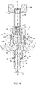
- Figure 4 shows an operating condition in which the carrier 3 is brought to the minimum distance possible and in which the lower seal gasket 43 is positioned substantially at the same height as the recess 47.
- the flange 58 is dragged by the fluid flow entering the channel 25 and moves the rod 51 vertically downwards.
- the spring 52 counters the lowering of the rod 51; the level of the cap 56 on the cylinder 50, on which several flow measurement scales are screen-printed, indicates the flow level passing through the flowmeter.
- Figure 3 shows a condition of intermediate opening of the flowmeter 1 and memorizing of said opening value.
- the carrier 3 is positioned by means of the ring 35 in any intermediate position desired between those illustrated in figures 2 and 4 .
- the user applies a torque to the ring 22 greater than the predetermined value to slide the linearly grooved coupling between the portion 17 of the central body 2 and the annular portion 23 of the ring 22. As the latter rotates, due to the thread between the portion 18 and the annular portion 24, it moves away from the fastening portion 6 until it touches the head 33 of the carrier 3.
- the flow memorization function is obtained by using one single ring 22 comprising two portions, one of which is threaded and configured to cause the ring to slide on the central portion 2 and the other coupled to the central portion 2 by means of a shaft-hub coupling which slides only when a predetermined torque value is exceeded.
- the ring 22, made in one single piece, is therefore compact, inexpensive and easy to produce.
- seats 46 having different section allows finer regulation of the fluid flow. Compared to the known solutions, in which one single revolution of the ring allows regulation of the flow between the maximum and minimum values, two or more revolutions of the ring 35 are necessary to regulate the flow of the flowmeter 1 according to the invention.
- the machined surface 22a facilitates use by a user, making it easy to rotate the ring 22.
- the seats 46 could have a different shape from the one described or again could have a constant section, with the openings 40 having a section varying from one another.
- the carrier 3 could be made in several parts integral with one another.
Landscapes
- Physics & Mathematics (AREA)
- Fluid Mechanics (AREA)
- General Physics & Mathematics (AREA)
- Measuring Volume Flow (AREA)
Claims (9)
- Durchflussmesser (1) mit einem Hauptkörper (2), einem Träger (3) und einer Messeinheit(4), die von dem Träger (3) getragen wird und sich innerhalb desselben erstreckt, wobei der Hauptkörper (2) zum Einsetzen in eine Öffnung eines Kopfes (8) eines thermohydraulischen Kreislaufs mittels eines Befestigungsabschnitts (6) ausgebildet ist, wobei sich der Träger (3) innerhalb des Hauptkörpers (2) und koaxial zum Hauptkörper (2) befindet und derart ausgebildet ist, dass er den Durchfluss eines Fluidstroms auf Basis der relativen Position zwischen dem Träger (3) und dem Hauptkörper (2) zulässt, wobei der Durchflussmesser (1) Durchflussregulierungsmittel und Durchflussmengenspeicherungsmittel umfassen, wobei die Durchflussregulierungsmittel einen ersten Ring (35) umfassen, wobei der erste Ring (35) von dem Träger (3) getragen wird und derart ausgebildet ist, dass er die Position des Trägers (3) in Bezug auf den Hauptkörper (2) reguliert, und die Speicherungsmittel einen zweiten Ring (22) umfassen, der von dem Hauptkörper (2) getragen wird und so ausgebildet ist, dass er die Position des Trägers (3) in Bezug auf den Hauptkörper (2) speichert, wobei der Hauptkörper (2) eine Außenfläche (17a) umfasst, die mit einer entsprechenden Innenfläche (23a) des zweiten Rings (22) zusammenwirkt, wobei der zweite Ring (22) in Bezug auf den Hauptkörper (2) rotieren kann;
dadurch gekennzeichnet, dass die Drehung des zweiten Rings (22) in Bezug auf den Hauptkörper (2) mittels eines Gewindes (20) erfolgt, das zwischen der Innenfläche (23a) des zweiten Rings (22) und der Außenfläche (17a) des Hauptkörpers (2) aufgenommen ist, und dass die Flächen (17a, 23a) so bearbeitet sind, dass sie ferner eine linear gerillte Keilverbindung bilden, um das drehende Gleiten des zweiten Rings (22) in Bezug auf den Hauptkörper (2) zu ermöglichen, wenn ein Drehmoment, das größer als ein vorbestimmter Wert ist, auf den ersteren angewendet wird. - Durchflussmesser nach Anspruch 1, wobei die Relativbewegung zwischen dem Träger (3) und dem Hauptkörper (2) vertikal vorgesehen ist und der Durchfluss abnimmt, wenn sich der Träger (3) von dem Befestigungsabschnitt (6) des Hauptkörpers (2) entfernt.
- Durchflussmesser nach Anspruch 1 oder 2, wobei der erste Ring (35) einteilig mit dem Träger (3) hergestellt ist.
- Durchflussmesser nach einem der vorangegangenen Ansprüche, wobei der Hauptkörper (2) eine Vielzahl an Öffnungen (46) umfasst, die dazu ausgebildet sind, dass sie den Durchgang des Fluidstroms zum Träger (3) ermöglichen.
- Durchflussmesser nach Anspruch 4, wobei die Öffnungen (46) eine im Wesentlichen rechteckige Form aufweisen, und dass eine Öffnung der Vielzahl an Öffnungen (46) einen unterschiedlichen Fluiddurchgangsabschnitt in Bezug auf die anderen Öffnungen (46) aufweist.
- Durchflussmesser nach einem der vorangegangenen Ansprüche, wobei der Hauptkörper (2) und der Träger (3) koaxial ausgebildet sind, wobei der Träger (3) in den Hauptkörper (2) eingesetzt ist und sich relativ zu diesem mittels einer Gewindeverbindung (36) bewegt, die zwischen einer Außenfläche des Trägers (3) und einer Innenfläche des Hauptkörpers (2) definiert ist.
- Durchflussmesser nach einem der vorangegangenen Ansprüche, wobei die ersten und zweiten Ringe (22, 35) jeweils eine Außenfläche (24a, 35a) mit einer Oberflächenbehandlung zur Verbesserung der Griffigkeit der ersten und zweiten Ringe (22, 35) aufweisen.
- Durchflussmesser nach einem der vorangegangenen Ansprüche, wobei der Träger Mittel zur Anzeige der Durchflussmenge trägt.
- Durchflussmesser nach einem der vorangegangenen Ansprüche, wobei die vollständige Regulierung des Fluidstroms in zumindest zwei Umdrehungen des Trägers (3) in Bezug auf den Hauptkörper (2) stattfindet.
Applications Claiming Priority (1)
| Application Number | Priority Date | Filing Date | Title |
|---|---|---|---|
| ITUB2016A000084A ITUB20160084A1 (it) | 2016-02-02 | 2016-02-02 | Flussimetro per impianti termoidraulici |
Publications (2)
| Publication Number | Publication Date |
|---|---|
| EP3203192A1 EP3203192A1 (de) | 2017-08-09 |
| EP3203192B1 true EP3203192B1 (de) | 2022-06-29 |
Family
ID=55969214
Family Applications (1)
| Application Number | Title | Priority Date | Filing Date |
|---|---|---|---|
| EP17154490.1A Active EP3203192B1 (de) | 2016-02-02 | 2017-02-02 | Durchflussmesser für thermohydraulische systeme |
Country Status (3)
| Country | Link |
|---|---|
| EP (1) | EP3203192B1 (de) |
| ES (1) | ES2926956T3 (de) |
| IT (1) | ITUB20160084A1 (de) |
Families Citing this family (1)
| Publication number | Priority date | Publication date | Assignee | Title |
|---|---|---|---|---|
| PL131967U1 (pl) * | 2024-02-15 | 2025-08-18 | Szymon Błasiak | Przepływomierz do regulacji czynnika grzewczego |
Citations (1)
| Publication number | Priority date | Publication date | Assignee | Title |
|---|---|---|---|---|
| EP1898134A2 (de) * | 2006-09-06 | 2008-03-12 | Werner Helmstädter | Drosseleinrichtung für Heiz- und Kühlanlagen |
Family Cites Families (4)
| Publication number | Priority date | Publication date | Assignee | Title |
|---|---|---|---|---|
| DE20117196U1 (de) * | 2001-10-19 | 2002-02-14 | AFRISO Euro-Index GmbH für Sicherungsarmaturen und Füllstandsmessung, 74363 Güglingen | Verteilerventileinsatz mit Durchflussmesser |
| DE602005015448D1 (de) * | 2004-05-17 | 2009-08-27 | Emmeti Spa | |
| DE102008010347A1 (de) * | 2008-02-13 | 2009-08-20 | Straub Ohg | Verteilerventil mit integrierter Durchflussmesseinrichtung |
| DE102014117629A1 (de) * | 2014-12-01 | 2016-06-02 | Peter Langbein | Verteilerventil mit integrierter Durchflussmesseinrichtung |
-
2016
- 2016-02-02 IT ITUB2016A000084A patent/ITUB20160084A1/it unknown
-
2017
- 2017-02-02 EP EP17154490.1A patent/EP3203192B1/de active Active
- 2017-02-02 ES ES17154490T patent/ES2926956T3/es active Active
Patent Citations (1)
| Publication number | Priority date | Publication date | Assignee | Title |
|---|---|---|---|---|
| EP1898134A2 (de) * | 2006-09-06 | 2008-03-12 | Werner Helmstädter | Drosseleinrichtung für Heiz- und Kühlanlagen |
Also Published As
| Publication number | Publication date |
|---|---|
| ES2926956T3 (es) | 2022-10-31 |
| EP3203192A1 (de) | 2017-08-09 |
| ITUB20160084A1 (it) | 2017-08-02 |
Similar Documents
| Publication | Publication Date | Title |
|---|---|---|
| EP1596110B1 (de) | Mischventil für Wasser | |
| US10025326B2 (en) | Thermostatic mixer valve | |
| RU2670003C1 (ru) | Клапан разности давления с промыванием | |
| US3131716A (en) | Flow control valves | |
| RU2588907C1 (ru) | Двухвентильный смеситель с раздельным регулированием температуры и напора воды | |
| US20220236089A1 (en) | Flow Sensor Gauge | |
| US20100307611A1 (en) | Distribution valve with integrated flow metering unit | |
| EP3203192A1 (de) | Durchflussmesser für thermohydraulische systeme | |
| US10634264B2 (en) | Indicator of the opening and/or closing status of a tap or a pressure reducer | |
| US6119724A (en) | Two-way valve for regulating and measuring the flow rate of a fluid | |
| RU2606541C1 (ru) | Распределительный клапан со встроенным блоком расходомера | |
| KR20110115396A (ko) | 유량 조절용 볼 밸브 | |
| CN105402455B (zh) | 具有伸缩式感测管的流体调节器 | |
| CN204201177U (zh) | 耐高压单柄双控恒温恒压龙头 | |
| EP2942573A1 (de) | Ventilanordnung | |
| KR100922006B1 (ko) | 차단 밸브 기능이 구비된 유량조절밸브 | |
| KR101128975B1 (ko) | 유량 조절 밸브 | |
| EP0052743A1 (de) | Abdichtung für Fluidazulauföffnungen in Einhebel-Mischventilen | |
| CN104315202A (zh) | 单柄双控恒温衡压龙头 | |
| GB2088531A (en) | A manual control device for a central heating valve | |
| KR102649552B1 (ko) | 유량조절밸브 | |
| US1787215A (en) | Mixing valve | |
| US2822001A (en) | Hot and cold water temperature controlling and mixing device | |
| DE202015100834U1 (de) | Durchflussmengenregler für eine Heizungsanlage | |
| CN214999576U (zh) | 一种流量调节装置 |
Legal Events
| Date | Code | Title | Description |
|---|---|---|---|
| PUAI | Public reference made under article 153(3) epc to a published international application that has entered the european phase |
Free format text: ORIGINAL CODE: 0009012 |
|
| STAA | Information on the status of an ep patent application or granted ep patent |
Free format text: STATUS: THE APPLICATION HAS BEEN PUBLISHED |
|
| AK | Designated contracting states |
Kind code of ref document: A1 Designated state(s): AL AT BE BG CH CY CZ DE DK EE ES FI FR GB GR HR HU IE IS IT LI LT LU LV MC MK MT NL NO PL PT RO RS SE SI SK SM TR |
|
| AX | Request for extension of the european patent |
Extension state: BA ME |
|
| STAA | Information on the status of an ep patent application or granted ep patent |
Free format text: STATUS: REQUEST FOR EXAMINATION WAS MADE |
|
| 17P | Request for examination filed |
Effective date: 20171024 |
|
| RBV | Designated contracting states (corrected) |
Designated state(s): AL AT BE BG CH CY CZ DE DK EE ES FI FR GB GR HR HU IE IS IT LI LT LU LV MC MK MT NL NO PL PT RO RS SE SI SK SM TR |
|
| STAA | Information on the status of an ep patent application or granted ep patent |
Free format text: STATUS: EXAMINATION IS IN PROGRESS |
|
| 17Q | First examination report despatched |
Effective date: 20200714 |
|
| GRAP | Despatch of communication of intention to grant a patent |
Free format text: ORIGINAL CODE: EPIDOSNIGR1 |
|
| STAA | Information on the status of an ep patent application or granted ep patent |
Free format text: STATUS: GRANT OF PATENT IS INTENDED |
|
| RIC1 | Information provided on ipc code assigned before grant |
Ipc: G01F 15/00 20060101ALN20220106BHEP Ipc: F24D 19/10 20060101ALI20220106BHEP Ipc: G01F 1/26 20060101AFI20220106BHEP |
|
| INTG | Intention to grant announced |
Effective date: 20220121 |
|
| GRAS | Grant fee paid |
Free format text: ORIGINAL CODE: EPIDOSNIGR3 |
|
| GRAA | (expected) grant |
Free format text: ORIGINAL CODE: 0009210 |
|
| STAA | Information on the status of an ep patent application or granted ep patent |
Free format text: STATUS: THE PATENT HAS BEEN GRANTED |
|
| AK | Designated contracting states |
Kind code of ref document: B1 Designated state(s): AL AT BE BG CH CY CZ DE DK EE ES FI FR GB GR HR HU IE IS IT LI LT LU LV MC MK MT NL NO PL PT RO RS SE SI SK SM TR |
|
| REG | Reference to a national code |
Ref country code: CH Ref legal event code: EP |
|
| REG | Reference to a national code |
Ref country code: AT Ref legal event code: REF Ref document number: 1501630 Country of ref document: AT Kind code of ref document: T Effective date: 20220715 |
|
| REG | Reference to a national code |
Ref country code: IE Ref legal event code: FG4D |
|
| REG | Reference to a national code |
Ref country code: DE Ref legal event code: R096 Ref document number: 602017058927 Country of ref document: DE |
|
| REG | Reference to a national code |
Ref country code: LT Ref legal event code: MG9D |
|
| PG25 | Lapsed in a contracting state [announced via postgrant information from national office to epo] |
Ref country code: SE Free format text: LAPSE BECAUSE OF FAILURE TO SUBMIT A TRANSLATION OF THE DESCRIPTION OR TO PAY THE FEE WITHIN THE PRESCRIBED TIME-LIMIT Effective date: 20220629 Ref country code: NO Free format text: LAPSE BECAUSE OF FAILURE TO SUBMIT A TRANSLATION OF THE DESCRIPTION OR TO PAY THE FEE WITHIN THE PRESCRIBED TIME-LIMIT Effective date: 20220929 Ref country code: LT Free format text: LAPSE BECAUSE OF FAILURE TO SUBMIT A TRANSLATION OF THE DESCRIPTION OR TO PAY THE FEE WITHIN THE PRESCRIBED TIME-LIMIT Effective date: 20220629 Ref country code: HR Free format text: LAPSE BECAUSE OF FAILURE TO SUBMIT A TRANSLATION OF THE DESCRIPTION OR TO PAY THE FEE WITHIN THE PRESCRIBED TIME-LIMIT Effective date: 20220629 Ref country code: GR Free format text: LAPSE BECAUSE OF FAILURE TO SUBMIT A TRANSLATION OF THE DESCRIPTION OR TO PAY THE FEE WITHIN THE PRESCRIBED TIME-LIMIT Effective date: 20220930 Ref country code: FI Free format text: LAPSE BECAUSE OF FAILURE TO SUBMIT A TRANSLATION OF THE DESCRIPTION OR TO PAY THE FEE WITHIN THE PRESCRIBED TIME-LIMIT Effective date: 20220629 Ref country code: BG Free format text: LAPSE BECAUSE OF FAILURE TO SUBMIT A TRANSLATION OF THE DESCRIPTION OR TO PAY THE FEE WITHIN THE PRESCRIBED TIME-LIMIT Effective date: 20220929 |
|
| REG | Reference to a national code |
Ref country code: ES Ref legal event code: FG2A Ref document number: 2926956 Country of ref document: ES Kind code of ref document: T3 Effective date: 20221031 |
|
| REG | Reference to a national code |
Ref country code: NL Ref legal event code: MP Effective date: 20220629 |
|
| REG | Reference to a national code |
Ref country code: AT Ref legal event code: MK05 Ref document number: 1501630 Country of ref document: AT Kind code of ref document: T Effective date: 20220629 |
|
| PG25 | Lapsed in a contracting state [announced via postgrant information from national office to epo] |
Ref country code: RS Free format text: LAPSE BECAUSE OF FAILURE TO SUBMIT A TRANSLATION OF THE DESCRIPTION OR TO PAY THE FEE WITHIN THE PRESCRIBED TIME-LIMIT Effective date: 20220629 Ref country code: LV Free format text: LAPSE BECAUSE OF FAILURE TO SUBMIT A TRANSLATION OF THE DESCRIPTION OR TO PAY THE FEE WITHIN THE PRESCRIBED TIME-LIMIT Effective date: 20220629 |
|
| PG25 | Lapsed in a contracting state [announced via postgrant information from national office to epo] |
Ref country code: NL Free format text: LAPSE BECAUSE OF FAILURE TO SUBMIT A TRANSLATION OF THE DESCRIPTION OR TO PAY THE FEE WITHIN THE PRESCRIBED TIME-LIMIT Effective date: 20220629 |
|
| PG25 | Lapsed in a contracting state [announced via postgrant information from national office to epo] |
Ref country code: SM Free format text: LAPSE BECAUSE OF FAILURE TO SUBMIT A TRANSLATION OF THE DESCRIPTION OR TO PAY THE FEE WITHIN THE PRESCRIBED TIME-LIMIT Effective date: 20220629 Ref country code: SK Free format text: LAPSE BECAUSE OF FAILURE TO SUBMIT A TRANSLATION OF THE DESCRIPTION OR TO PAY THE FEE WITHIN THE PRESCRIBED TIME-LIMIT Effective date: 20220629 Ref country code: RO Free format text: LAPSE BECAUSE OF FAILURE TO SUBMIT A TRANSLATION OF THE DESCRIPTION OR TO PAY THE FEE WITHIN THE PRESCRIBED TIME-LIMIT Effective date: 20220629 Ref country code: PT Free format text: LAPSE BECAUSE OF FAILURE TO SUBMIT A TRANSLATION OF THE DESCRIPTION OR TO PAY THE FEE WITHIN THE PRESCRIBED TIME-LIMIT Effective date: 20221031 Ref country code: EE Free format text: LAPSE BECAUSE OF FAILURE TO SUBMIT A TRANSLATION OF THE DESCRIPTION OR TO PAY THE FEE WITHIN THE PRESCRIBED TIME-LIMIT Effective date: 20220629 Ref country code: AT Free format text: LAPSE BECAUSE OF FAILURE TO SUBMIT A TRANSLATION OF THE DESCRIPTION OR TO PAY THE FEE WITHIN THE PRESCRIBED TIME-LIMIT Effective date: 20220629 |
|
| PG25 | Lapsed in a contracting state [announced via postgrant information from national office to epo] |
Ref country code: PL Free format text: LAPSE BECAUSE OF FAILURE TO SUBMIT A TRANSLATION OF THE DESCRIPTION OR TO PAY THE FEE WITHIN THE PRESCRIBED TIME-LIMIT Effective date: 20220629 Ref country code: IS Free format text: LAPSE BECAUSE OF FAILURE TO SUBMIT A TRANSLATION OF THE DESCRIPTION OR TO PAY THE FEE WITHIN THE PRESCRIBED TIME-LIMIT Effective date: 20221029 |
|
| REG | Reference to a national code |
Ref country code: DE Ref legal event code: R097 Ref document number: 602017058927 Country of ref document: DE |
|
| PG25 | Lapsed in a contracting state [announced via postgrant information from national office to epo] |
Ref country code: AL Free format text: LAPSE BECAUSE OF FAILURE TO SUBMIT A TRANSLATION OF THE DESCRIPTION OR TO PAY THE FEE WITHIN THE PRESCRIBED TIME-LIMIT Effective date: 20220629 |
|
| PG25 | Lapsed in a contracting state [announced via postgrant information from national office to epo] |
Ref country code: DK Free format text: LAPSE BECAUSE OF FAILURE TO SUBMIT A TRANSLATION OF THE DESCRIPTION OR TO PAY THE FEE WITHIN THE PRESCRIBED TIME-LIMIT Effective date: 20220629 Ref country code: CZ Free format text: LAPSE BECAUSE OF FAILURE TO SUBMIT A TRANSLATION OF THE DESCRIPTION OR TO PAY THE FEE WITHIN THE PRESCRIBED TIME-LIMIT Effective date: 20220629 |
|
| PGFP | Annual fee paid to national office [announced via postgrant information from national office to epo] |
Ref country code: FR Payment date: 20230223 Year of fee payment: 7 Ref country code: ES Payment date: 20230323 Year of fee payment: 7 Ref country code: CH Payment date: 20230307 Year of fee payment: 7 |
|
| PLBE | No opposition filed within time limit |
Free format text: ORIGINAL CODE: 0009261 |
|
| STAA | Information on the status of an ep patent application or granted ep patent |
Free format text: STATUS: NO OPPOSITION FILED WITHIN TIME LIMIT |
|
| PGFP | Annual fee paid to national office [announced via postgrant information from national office to epo] |
Ref country code: IT Payment date: 20230207 Year of fee payment: 7 Ref country code: DE Payment date: 20230227 Year of fee payment: 7 Ref country code: BE Payment date: 20230222 Year of fee payment: 7 |
|
| 26N | No opposition filed |
Effective date: 20230330 |
|
| PG25 | Lapsed in a contracting state [announced via postgrant information from national office to epo] |
Ref country code: SI Free format text: LAPSE BECAUSE OF FAILURE TO SUBMIT A TRANSLATION OF THE DESCRIPTION OR TO PAY THE FEE WITHIN THE PRESCRIBED TIME-LIMIT Effective date: 20220629 |
|
| PG25 | Lapsed in a contracting state [announced via postgrant information from national office to epo] |
Ref country code: MC Free format text: LAPSE BECAUSE OF FAILURE TO SUBMIT A TRANSLATION OF THE DESCRIPTION OR TO PAY THE FEE WITHIN THE PRESCRIBED TIME-LIMIT Effective date: 20220629 |
|
| GBPC | Gb: european patent ceased through non-payment of renewal fee |
Effective date: 20230202 |
|
| PG25 | Lapsed in a contracting state [announced via postgrant information from national office to epo] |
Ref country code: LU Free format text: LAPSE BECAUSE OF NON-PAYMENT OF DUE FEES Effective date: 20230202 |
|
| REG | Reference to a national code |
Ref country code: IE Ref legal event code: MM4A |
|
| PG25 | Lapsed in a contracting state [announced via postgrant information from national office to epo] |
Ref country code: GB Free format text: LAPSE BECAUSE OF NON-PAYMENT OF DUE FEES Effective date: 20230202 |
|
| PG25 | Lapsed in a contracting state [announced via postgrant information from national office to epo] |
Ref country code: IE Free format text: LAPSE BECAUSE OF NON-PAYMENT OF DUE FEES Effective date: 20230202 Ref country code: GB Free format text: LAPSE BECAUSE OF NON-PAYMENT OF DUE FEES Effective date: 20230202 |
|
| REG | Reference to a national code |
Ref country code: DE Ref legal event code: R119 Ref document number: 602017058927 Country of ref document: DE |
|
| REG | Reference to a national code |
Ref country code: CH Ref legal event code: PL |
|
| PG25 | Lapsed in a contracting state [announced via postgrant information from national office to epo] |
Ref country code: CH Free format text: LAPSE BECAUSE OF NON-PAYMENT OF DUE FEES Effective date: 20240229 |
|
| PG25 | Lapsed in a contracting state [announced via postgrant information from national office to epo] |
Ref country code: CH Free format text: LAPSE BECAUSE OF NON-PAYMENT OF DUE FEES Effective date: 20240229 |
|
| PG25 | Lapsed in a contracting state [announced via postgrant information from national office to epo] |
Ref country code: BG Free format text: LAPSE BECAUSE OF FAILURE TO SUBMIT A TRANSLATION OF THE DESCRIPTION OR TO PAY THE FEE WITHIN THE PRESCRIBED TIME-LIMIT Effective date: 20220629 |
|
| PG25 | Lapsed in a contracting state [announced via postgrant information from national office to epo] |
Ref country code: BG Free format text: LAPSE BECAUSE OF FAILURE TO SUBMIT A TRANSLATION OF THE DESCRIPTION OR TO PAY THE FEE WITHIN THE PRESCRIBED TIME-LIMIT Effective date: 20220629 |
|
| REG | Reference to a national code |
Ref country code: BE Ref legal event code: MM Effective date: 20240229 |
|
| PG25 | Lapsed in a contracting state [announced via postgrant information from national office to epo] |
Ref country code: DE Free format text: LAPSE BECAUSE OF NON-PAYMENT OF DUE FEES Effective date: 20240903 |
|
| PG25 | Lapsed in a contracting state [announced via postgrant information from national office to epo] |
Ref country code: BE Free format text: LAPSE BECAUSE OF NON-PAYMENT OF DUE FEES Effective date: 20240229 |
|
| PG25 | Lapsed in a contracting state [announced via postgrant information from national office to epo] |
Ref country code: FR Free format text: LAPSE BECAUSE OF NON-PAYMENT OF DUE FEES Effective date: 20240229 |
|
| PG25 | Lapsed in a contracting state [announced via postgrant information from national office to epo] |
Ref country code: FR Free format text: LAPSE BECAUSE OF NON-PAYMENT OF DUE FEES Effective date: 20240229 Ref country code: DE Free format text: LAPSE BECAUSE OF NON-PAYMENT OF DUE FEES Effective date: 20240903 Ref country code: BE Free format text: LAPSE BECAUSE OF NON-PAYMENT OF DUE FEES Effective date: 20240229 |
|
| PG25 | Lapsed in a contracting state [announced via postgrant information from national office to epo] |
Ref country code: IT Free format text: LAPSE BECAUSE OF NON-PAYMENT OF DUE FEES Effective date: 20240202 |
|
| REG | Reference to a national code |
Ref country code: ES Ref legal event code: FD2A Effective date: 20250326 |
|
| PG25 | Lapsed in a contracting state [announced via postgrant information from national office to epo] |
Ref country code: ES Free format text: LAPSE BECAUSE OF NON-PAYMENT OF DUE FEES Effective date: 20240203 |
|
| PG25 | Lapsed in a contracting state [announced via postgrant information from national office to epo] |
Ref country code: CY Free format text: LAPSE BECAUSE OF FAILURE TO SUBMIT A TRANSLATION OF THE DESCRIPTION OR TO PAY THE FEE WITHIN THE PRESCRIBED TIME-LIMIT; INVALID AB INITIO Effective date: 20170202 |
|
| PG25 | Lapsed in a contracting state [announced via postgrant information from national office to epo] |
Ref country code: HU Free format text: LAPSE BECAUSE OF FAILURE TO SUBMIT A TRANSLATION OF THE DESCRIPTION OR TO PAY THE FEE WITHIN THE PRESCRIBED TIME-LIMIT; INVALID AB INITIO Effective date: 20170202 |
|
| PG25 | Lapsed in a contracting state [announced via postgrant information from national office to epo] |
Ref country code: TR Free format text: LAPSE BECAUSE OF FAILURE TO SUBMIT A TRANSLATION OF THE DESCRIPTION OR TO PAY THE FEE WITHIN THE PRESCRIBED TIME-LIMIT Effective date: 20220629 |