EP3203205A1 - Dispositif de détection de pression - Google Patents
Dispositif de détection de pression Download PDFInfo
- Publication number
- EP3203205A1 EP3203205A1 EP17154136.0A EP17154136A EP3203205A1 EP 3203205 A1 EP3203205 A1 EP 3203205A1 EP 17154136 A EP17154136 A EP 17154136A EP 3203205 A1 EP3203205 A1 EP 3203205A1
- Authority
- EP
- European Patent Office
- Prior art keywords
- pressure
- flow channel
- pressure detection
- pair
- peripheral surface
- Prior art date
- Legal status (The legal status is an assumption and is not a legal conclusion. Google has not performed a legal analysis and makes no representation as to the accuracy of the status listed.)
- Granted
Links
Images




Classifications
-
- A—HUMAN NECESSITIES
- A61—MEDICAL OR VETERINARY SCIENCE; HYGIENE
- A61M—DEVICES FOR INTRODUCING MEDIA INTO, OR ONTO, THE BODY; DEVICES FOR TRANSDUCING BODY MEDIA OR FOR TAKING MEDIA FROM THE BODY; DEVICES FOR PRODUCING OR ENDING SLEEP OR STUPOR
- A61M1/00—Suction or pumping devices for medical purposes; Devices for carrying-off, for treatment of, or for carrying-over, body-liquids; Drainage systems
- A61M1/36—Other treatment of blood in a by-pass of the natural circulatory system, e.g. temperature adaptation, irradiation ; Extra-corporeal blood circuits
- A61M1/3621—Extra-corporeal blood circuits
- A61M1/3639—Blood pressure control, pressure transducers specially adapted therefor
-
- G—PHYSICS
- G01—MEASURING; TESTING
- G01L—MEASURING FORCE, STRESS, TORQUE, WORK, MECHANICAL POWER, MECHANICAL EFFICIENCY, OR FLUID PRESSURE
- G01L7/00—Measuring the steady or quasi-steady pressure of a fluid or a fluent solid material by mechanical or fluid pressure-sensitive elements
- G01L7/02—Measuring the steady or quasi-steady pressure of a fluid or a fluent solid material by mechanical or fluid pressure-sensitive elements in the form of elastically-deformable gauges
- G01L7/022—Measuring the steady or quasi-steady pressure of a fluid or a fluent solid material by mechanical or fluid pressure-sensitive elements in the form of elastically-deformable gauges constructional details, e.g. mounting of elastically-deformable gauges
-
- A—HUMAN NECESSITIES
- A61—MEDICAL OR VETERINARY SCIENCE; HYGIENE
- A61M—DEVICES FOR INTRODUCING MEDIA INTO, OR ONTO, THE BODY; DEVICES FOR TRANSDUCING BODY MEDIA OR FOR TAKING MEDIA FROM THE BODY; DEVICES FOR PRODUCING OR ENDING SLEEP OR STUPOR
- A61M1/00—Suction or pumping devices for medical purposes; Devices for carrying-off, for treatment of, or for carrying-over, body-liquids; Drainage systems
- A61M1/36—Other treatment of blood in a by-pass of the natural circulatory system, e.g. temperature adaptation, irradiation ; Extra-corporeal blood circuits
- A61M1/3672—Means preventing coagulation
-
- B—PERFORMING OPERATIONS; TRANSPORTING
- B29—WORKING OF PLASTICS; WORKING OF SUBSTANCES IN A PLASTIC STATE IN GENERAL
- B29C—SHAPING OR JOINING OF PLASTICS; SHAPING OF MATERIAL IN A PLASTIC STATE, NOT OTHERWISE PROVIDED FOR; AFTER-TREATMENT OF THE SHAPED PRODUCTS, e.g. REPAIRING
- B29C45/00—Injection moulding, i.e. forcing the required volume of moulding material through a nozzle into a closed mould; Apparatus therefor
- B29C45/0081—Injection moulding, i.e. forcing the required volume of moulding material through a nozzle into a closed mould; Apparatus therefor of objects with parts connected by a thin section, e.g. hinge, tear line
-
- G—PHYSICS
- G01—MEASURING; TESTING
- G01F—MEASURING VOLUME, VOLUME FLOW, MASS FLOW OR LIQUID LEVEL; METERING BY VOLUME
- G01F1/00—Measuring the volume flow or mass flow of fluid or fluent solid material wherein the fluid passes through a meter in a continuous flow
- G01F1/05—Measuring the volume flow or mass flow of fluid or fluent solid material wherein the fluid passes through a meter in a continuous flow by using mechanical effects
- G01F1/34—Measuring the volume flow or mass flow of fluid or fluent solid material wherein the fluid passes through a meter in a continuous flow by using mechanical effects by measuring pressure or differential pressure
- G01F1/36—Measuring the volume flow or mass flow of fluid or fluent solid material wherein the fluid passes through a meter in a continuous flow by using mechanical effects by measuring pressure or differential pressure the pressure or differential pressure being created by the use of flow constriction
- G01F1/38—Measuring the volume flow or mass flow of fluid or fluent solid material wherein the fluid passes through a meter in a continuous flow by using mechanical effects by measuring pressure or differential pressure the pressure or differential pressure being created by the use of flow constriction the pressure or differential pressure being measured by means of a movable element, e.g. diaphragm, piston, Bourdon tube or flexible capsule
- G01F1/383—Measuring the volume flow or mass flow of fluid or fluent solid material wherein the fluid passes through a meter in a continuous flow by using mechanical effects by measuring pressure or differential pressure the pressure or differential pressure being created by the use of flow constriction the pressure or differential pressure being measured by means of a movable element, e.g. diaphragm, piston, Bourdon tube or flexible capsule with electrical or electro-mechanical indication
-
- G—PHYSICS
- G01—MEASURING; TESTING
- G01L—MEASURING FORCE, STRESS, TORQUE, WORK, MECHANICAL POWER, MECHANICAL EFFICIENCY, OR FLUID PRESSURE
- G01L19/00—Details of, or accessories for, apparatus for measuring steady or quasi-steady pressure of a fluent medium insofar as such details or accessories are not special to particular types of pressure gauges
- G01L19/0007—Fluidic connecting means
-
- G—PHYSICS
- G01—MEASURING; TESTING
- G01L—MEASURING FORCE, STRESS, TORQUE, WORK, MECHANICAL POWER, MECHANICAL EFFICIENCY, OR FLUID PRESSURE
- G01L19/00—Details of, or accessories for, apparatus for measuring steady or quasi-steady pressure of a fluent medium insofar as such details or accessories are not special to particular types of pressure gauges
- G01L19/0007—Fluidic connecting means
- G01L19/0023—Fluidic connecting means for flowthrough systems having a flexible pressure transmitting element
-
- G—PHYSICS
- G01—MEASURING; TESTING
- G01L—MEASURING FORCE, STRESS, TORQUE, WORK, MECHANICAL POWER, MECHANICAL EFFICIENCY, OR FLUID PRESSURE
- G01L7/00—Measuring the steady or quasi-steady pressure of a fluid or a fluent solid material by mechanical or fluid pressure-sensitive elements
- G01L7/02—Measuring the steady or quasi-steady pressure of a fluid or a fluent solid material by mechanical or fluid pressure-sensitive elements in the form of elastically-deformable gauges
- G01L7/08—Measuring the steady or quasi-steady pressure of a fluid or a fluent solid material by mechanical or fluid pressure-sensitive elements in the form of elastically-deformable gauges of the flexible-diaphragm type
- G01L7/084—Measuring the steady or quasi-steady pressure of a fluid or a fluent solid material by mechanical or fluid pressure-sensitive elements in the form of elastically-deformable gauges of the flexible-diaphragm type with mechanical transmitting or indicating means
Definitions
- the present invention relates to a pressure detection device that detects a pressure of a fluid circulated through a flow channel.
- JP 2005-207946 An in-line type pressure sensor having a structure in which a body provided with a flow channel for circulating a liquid, such as a drug solution, and a sensor body for detecting a pressure of liquid transmitted to a pressure receiving surface through a protector are integrally formed has been conventionally known (for example, see Japanese Unexamined Patent Application, Publication No. 2005-207946 (hereinafter referred to as " JP 2005-207946 ”)).
- the pressure sensor disclosed in JP 2005-207946 detects the pressure of the fluid transmitted to the sensor body through the protector attached to a lower surface of the sensor body.
- the pressure sensor disclosed in JP 2005-207946 can obtain a detected value corresponding to a pressure at which the fluid presses the protector when the protector is pressed against the lower surface of the sensor body by the pressure of the fluid.
- a fluid introduction portion formed in the body is sealed with the sensor body, so that a small amount of fluid may accumulate in a space between the sensor body and the body. If the fluid is a coagulable fluid, such as blood, there is a possibility that an accumulated and solidified fluid may be recirculated through the flow channel.
- the present invention has been made in view of the above-mentioned circumstances, and an object of the present invention is to provide a pressure detection device capable of detecting a pressure of a fluid circulated through a flow channel, while preventing the occurrence of a malfunction due to the accumulation of the fluid in the flow channel.
- the present invention employs the following solutions.
- a pressure detection device includes: a pressure detection unit configured to detect a pressure to be transmitted to a pressure detection portion; and a flow channel unit including a flow channel body provided with a flow channel through which a fluid is circulated along a circulation direction from an inflow port to an outflow port.
- the flow channel body includes: a pair of end flow channels disposed at the inflow port and the outflow port, respectively; and a center flow channel including a pressure receiving portion having a thin film shape and disposed at a position sandwiched between the pair of end flow channels, a distance from an inner peripheral surface of the pressure receiving portion to an outer peripheral surface thereof being shorter than a distance from an inner peripheral surface of the pair of end flow channels to an outer peripheral surface thereof.
- the pair of end flow channels and the center flow channel are integrally formed of a flexible resin material.
- the pressure detection portion is disposed in such a manner that the pressure of the fluid circulated through the flow channel is transmitted via the pressure receiving portion.
- the pair of end flow channels and the center flow channel disposed at a position sandwiched between the pair of end flow channels are integrally formed of a flexible resin material. Accordingly, the flow channel body included in the pressure detection device according to one aspect of the present invention has no portion where a part of the portion is sealed with another member, so that a small amount of fluid does not accumulate on the sealed portion. Accordingly, even when a coagulable fluid, such as blood, is circulated, a malfunction that an accumulated and solidified fluid is recirculated through the flow channel can be prevented.
- the center flow channel includes the pressure receiving portion having a thin film shape.
- the pressure detection portion is disposed in such a manner that the pressure of the fluid circulated through the flow channel is transmitted via the pressure receiving portion having a thin film shape. Therefore, in the pressure detection device according to one aspect of the present invention, the pressure detection portion can appropriately detect the pressure of the fluid transmitted via the pressure receiving portion having a thin film shape.
- the pressure detection device of one aspect of the present invention it is possible to provide a pressure detection device capable of detecting a pressure of a fluid circulated through a flow channel, while preventing the occurrence of a malfunction due to the accumulation of the fluid in the flow channel.
- the center flow channel may have a structure in which a distance from an inner peripheral surface in a partial region of the center flow channel in a circumferential direction about the circulation direction to an outer peripheral surface thereof is shorter than a distance from an inner peripheral surface in another region of the center flow channel to an outer peripheral surface thereof, and the partial region is set as the pressure receiving portion.
- the partial region of the center flow channel in the circumferential direction is set as a region in which a displacement in the pressure of the fluid is more likely to occur than in the other region.
- the partial region is set as the pressure receiving portion, thereby making it possible to appropriately detect the pressure of the fluid.
- the center flow channel has a flow channel sectional area larger than that of the pair of end flow channels.
- a pair of connecting flow channels is formed to connect an end of the pair of end flow channels that is located closer to the center flow channel and both ends of the center flow channel.
- the pair of end flow channels, the center flow channel, and the pair of connecting flow channels are integrally formed of a flexible resin material.
- the pair of connecting flow channels is formed in such a manner that a flow channel sectional area of the pair of connecting flow channels gradually increases toward the both ends of the center flow channel.
- the pair of connecting flow channels connects the pair of end flow channels and the center flow channel so that the flow channel sectional area gradually increases toward both ends of the center flow channel from the pair of end flow channels. Therefore, when the fluid is circulated from the end flow channel disposed at the inflow port to the center flow channel, the fluid does not accumulate on the flow channel. Further, when the fluid is circulated from the center flow channel to the end flow channel where the outflow port is disposed, the fluid does not accumulate on the flow channel.
- the pressure detection device may have a structure in which the pressure detection unit includes: a pressure sensor including the pressure detection portion; and a pressure transmission portion disposed in a state where one end of the pressure transmission portion is in contact with the pressure detection portion and the other end of the pressure transmission portion is in contact with the pressure receiving portion, the pressure transmission portion being configured to transmit the pressure of the fluid received by the pressure receiving portion to the pressure detection portion, and the pressure transmission portion may displace the pressure receiving portion toward the flow channel and may be disposed in a state of receiving an urging force directed to the pressure detection portion from the pressure receiving portion.
- the pressure transmission portion disposed in a state where one end of the pressure transmission portion is in contact with the pressure detection portion and the other end thereof is in contact with the pressure receiving portion of the flow channel unit is disposed in a state of receiving an urging force directed to the pressure detection portion from the pressure receiving portion. Accordingly, even when the pressure of the fluid circulated through the flow channel is temporarily reduced and becomes a negative pressure, the pressure detection portion is in a state of receiving a pressure having a value obtained by subtracting a pressure value corresponding to a negative pressure from a pressure value equivalent to the urging force received by the pressure transmission portion from the pressure receiving portion. Thus, even when the pressure of the fluid is temporarily reduced and becomes a negative pressure, the pressure detection portion can obtain a pressure value obtained by subtracting a decrease in the pressure value corresponding to the negative pressure from the pressure value equivalent to the urging force received from the pressure receiving portion.
- the flow channel unit may be provided with a recess in which the pressure receiving portion is disposed; the pressure sensor may be disposed in contact with the flow channel unit so as to cover the recess; and a communication flow channel may be formed to allow an inside space and an outside space to communicate with each other, the inside space and the outside space being partitioned by the recess and the pressure sensor.
- the pressure detection device having a structure as described above may have an aspect in which the pressure transmission portion includes: a first pressure transmission member disposed in contact with the pressure receiving portion; and a second pressure transmission member disposed in contact with the pressure detection portion, and a contact area between the second pressure transmission member and the pressure detection portion is smaller than a contact area between the first pressure transmission member and the pressure receiving portion.
- the fluid pressure received by the first pressure transmission member from the pressure receiving portion can be transmitted in such a manner that the fluid pressure is locally concentrated on the pressure detection portion via the second pressure transmission member having a small contact area with an opposed member. Accordingly, the fluctuation in the pressure locally received by the pressure detection portion is increased with respect to the fluctuation in the fluid pressure, thereby making it possible to increase the accuracy of detecting the fluctuation in the fluid pressure.
- the pressure detection device may have an aspect in which the first pressure transmission member is a member formed into a spherical shape projecting toward the pressure receiving portion.
- the contact area where the first transmission member contacts the pressure receiving portion is maintained substantially constant, regardless of the displacement in the pressure receiving portion, and thus the accuracy of transmitting the pressure of the fluid from the pressure receiving portion to the first transmission member can be increased.
- the second pressure transmission member may be a member formed into a spherical shape projecting toward the pressure detection portion.
- the fluid pressure received by the first pressure transmission member from the pressure receiving portion can be transmitted in such a manner that the fluid pressure is locally concentrated on the pressure detection portion via the second pressure transmission member formed into a spherical shape. Accordingly, the fluctuation in the pressure locally received by the pressure detection portion is increased with respect to the fluctuation in the fluid pressure, and thus the accuracy of detecting the fluctuation in the fluid pressure can be increased.
- the pressure detection device may have a structure in which the pressure transmission portion is disposed in contact with both the pressure receiving portion and the pressure detection portion, and is formed into a spherical shape.
- the contact area where the pressure transmission portion contacts the pressure receiving portion is maintained substantially constant, regardless of the displacement in the pressure receiving portion, and thus the accuracy of transmitting the pressure of the fluid from the pressure receiving portion to the pressure transmission portion can be increased.
- the fluid pressure received by the pressure transmission portion from the pressure receiving portion can be transmitted in such a manner that the fluid pressure is locally concentrated on the pressure detection portion via the pressure transmission portion formed into a spherical shape. Accordingly, the fluctuation in the pressure locally received by the pressure detection portion is increased with respect to the fluctuation in the fluid pressure, and thus the accuracy of detecting the fluctuation in the fluid pressure can be increased.
- a pressure detection device capable of detecting a pressure of a fluid circulated through a flow channel, while preventing the occurrence of a malfunction due to the accumulation of the fluid in the flow channel.
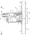
- a pressure detection device 100 according to a first embodiment of the present invention will be described below with reference to the drawings.
- the pressure detection device 100 of the first embodiment includes: a pressure detection unit 10 for detecting a pressure of a fluid; a flow channel unit 20 including a flow channel body 21 having a flow channel 21a formed therein; and a base portion 30 which is attached in a state where the flow channel unit 20 is sandwiched between the pressure detection unit 10 and the base portion 30.
- the flow channel 21a is a flow channel through which the fluid is circulated along a linear circulation direction from an inflow port 21b to an outflow port 21c.
- the base portion 30 is connected to a body portion 13 in such a manner that a fastening bolt 40 which is inserted from a fastening hole 30a which is formed in the base portion 30 is fastened to a fastening hole 13b which is formed in the body portion 13.
- the pressure detection unit 10 shown in Fig. 1 is a device that detects a pressure to be transmitted to a diaphragm 12a (pressure detection portion).
- the pressure detection unit 10 includes: a pressure sensor 12 that detects the pressure of the fluid transmitted from the flow channel body 21; the body portion 13 that accommodates the pressure sensor 12; a sensor holding portion 14 that holds the pressure sensor 12 in a state where the pressure sensor 12 is disposed in the body portion 13; a sensor substrate 15 for transmitting power and an electric signal between the pressure sensor 12 and a cable 200 connected to an external device (not shown); a zero point adjustment switch 16 for performing zero point adjustment of the pressure sensor 12; and a housing 17 that accommodates the sensor substrate 15.
- the components included in the pressure detection unit 10 will be described below.
- the pressure sensor 12 includes: the diaphragm 12a (pressure detection portion), which is formed into a thin film shape using a material (for example, sapphire) having a corrosion resistance; a strain resistance (not shown) which is attached to the diaphragm 12a; and a base portion 12b which holds the diaphragm 12a.
- the pressure sensor 12 is a strain sensor that outputs a pressure signal corresponding to the strain resistance that varies depending on the pressure transmitted to the diaphragm 12a.
- the body portion 13 is a member having a structure in which an upper member formed into a cylindrical shape about an axis line X and a lower member that accommodates the flow channel unit 20 are integrally formed. On the inner peripheral surface at an upper side of the body portion 13, a female screw 13a for attaching the sensor holding portion 14 to be described later is formed.
- fastening holes 13b are formed at a plurality of locations about the axis line X.
- the fastening bolts 40 inserted from the fastening holes 30a of the base portion 30 are fastened to the fastening holes 13b.
- the pressure sensor 12 is inserted into a central portion of the body portion 13 from above along the axis line X.
- the sensor holding portion 14 is a member formed into a cylindrical shape about the axis line X, and a male screw 14a is formed on an outer peripheral surface of the sensor holding portion 14.
- the sensor holding portion 14 holds the pressure sensor 12 at a predetermined position with respect to the body portion 13 in such a manner that the pressure sensor 12 is disposed on the inner peripheral side of the lower end of the body portion 13 and the male screw 14a formed on the outer peripheral surface is fastened to the female screw 13a which is formed in the inner peripheral surface of the body portion 13.
- the sensor substrate 15 includes, for example, an amplifier circuit (not shown) which amplifies a pressure signal output from the pressure sensor 12; an interface circuit which transmits the pressure signal amplified by the amplifier circuit to a pressure signal line (not shown) of the cable 200; a power supply circuit (not shown) which transmits a power supply voltage supplied from the outside via the cable 200 to the pressure sensor 12; and a zero point adjustment circuit (not shown) which performs zero point adjustment when the zero point adjustment switch 16 is pressed.
- an amplifier circuit (not shown) which amplifies a pressure signal output from the pressure sensor 12
- an interface circuit which transmits the pressure signal amplified by the amplifier circuit to a pressure signal line (not shown) of the cable 200
- a power supply circuit (not shown) which transmits a power supply voltage supplied from the outside via the cable 200 to the pressure sensor 12
- a zero point adjustment circuit (not shown) which performs zero point adjustment when the zero point adjustment switch 16 is pressed.
- the zero point adjustment switch 16 is a switch which is turned on when an operator presses a pressing portion 17a which is provided on an upper surface of the housing 17. When the zero point adjustment switch 16 is turned on, the zero point adjustment circuit adjusts the pressure signal output from the pressure sensor 12 at that time to be set as an initial value (zero).
- This operation is a manipulation necessary at the time of starting the measurement of the pressure signal after the pressure detection device 100 is assembled. This is because it is necessary to preliminarily set, as a pressure detection value zero, a state in which an urging force from a pressure transmission portion 11 is supplied to the pressure sensor 12 so that the pressure detection device 100 can measure a negative pressure. Thus, even when the urging force supplied to the pressure sensor 12 by the pressure transmission portion 11 varies depending on the individual pressure detection device 100, the state in which the pressure detection value is zero can be appropriately set and the pressure can be accurately measured.
- the housing 17 is a member formed into a cylindrical shape about the axis line X, and the inner peripheral surface at the lower end of the housing 17 is attached to the outer peripheral surface on the upper end side of the body portion 13.
- the housing 17 accommodates the sensor substrate 15 in the inner peripheral side thereof.
- the inside cover 18 is a cylindrical member which is disposed in the housing 17 and has an inner peripheral surface disposed in contact with the outer peripheral surface of the upper portion of the sensor holding portion 14.
- the outer peripheral surface of the inside cover 18 about the axis line X is disposed in contact with the inner peripheral surface of the housing 17.
- An inflow pipe (not shown) through which the fluid is caused to flow into the inflow port 21b is attached to the inflow port 21b of the flow channel unit 20, and an outflow pipe (not shown) for circulating the fluid flowing from the outflow port 21c is attached to the outflow port 21c of the flow channel unit 20.
- the pressure of the fluid circulated through the flow channel 21a from the inflow port 21b toward the outflow port 21c is detected by the pressure detection unit 10.
- the fluid described herein refers to, for example, a liquid such as blood or dialysis fluid.
- the flow channel body 21 is a member integrally formed of a flexible resin material such as silicon, PVC, or PFA.
- the flow channel body 21 is provided with a recess 21d which has a circular planar shape.
- a portion where the recess 21d of the flow channel body 21 is formed corresponds to a central portion 22a of the diaphragm 22 (pressure receiving portion).
- the central portion 22a is formed into a thin film shape with a flow channel thickness T2.
- the pressure sensor 12 is disposed in the recess 21d in such a manner that the diaphragm 12a contacts the outer peripheral surface of the diaphragm 22.
- the central portion 22a of the diaphragm 22 Since the central portion 22a of the diaphragm 22 is formed into a thin film shape, the central portion 22a receives the pressure of the fluid, which is circulated through the flow channel 21a, and is displaced in the direction along the axis line X.
- the diaphragm 12a of the pressure sensor 12 is disposed so as to transmit the pressure of the fluid circulated through the flow channel 21a via the diaphragm 22.
- the flow channel body 21 includes: an inflow-side end flow channel 24 disposed at the inflow port 21b; an outflow-side end flow channel 25 disposed at the outflow port 21c; a center flow channel 28 disposed at a position sandwiched between the inflow-side end flow channel 24 and the outflow-side end flow channel 25; an inflow-side connecting flow channel 26 formed so as to connect the center flow channel 28 and an end of the inflow-side end flow channel 24 that is located closer to the center flow channel 28; and an outflow-side connecting flow channel 27 formed so as to connect the center flow channel 28 and an end of the outflow-side end flow channel 25 that is located closer to the center flow channel 28.
- the pair of end flow channels (the inflow-side end flow channel 24 and the outflow-side end flow channel 25), the pair of connecting flow channels (the inflow-side connecting flow channel 26 and the outflow-side connecting flow channel 27), and the center flow channel 28 are integrally formed (integrally molded) of the above-mentioned flexible resin material.
- These flow channels are integrally molded and formed as a single member, so that there is no connected portion, such as a seam, at each portion where these flow channels are connected.
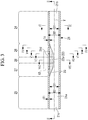
- the inflow-side end flow channel 24 is a flow channel having an inner peripheral surface and an outer peripheral surface which are formed in a cylindrical shape extending along an axis line Y. As shown in Fig. 3 , an inner diameter D1 and an outer diameter D2 of the inflow-side end flow channel 24 are constant in a range from the inflow port 21b to the inflow-side connecting flow channel 26.
- a flow channel thickness T1 which is a distance from the inner peripheral surface of the inflow-side end flow channel 24 to the outer peripheral surface thereof is constant over the perimeter in the circumferential direction about the axis line Y.
- the outflow-side end flow channel 25 is a flow channel having an inner peripheral surface and an outer peripheral surface which are formed into a cylindrical shape extending along the axis line Y. As shown in Fig. 3 , the inner diameter D1 and the outer diameter D2 of the outflow-side end flow channel 25 are constant in a range from the outflow-side connecting flow channel 27 to the outflow port 21c.
- the flow channel thickness T1 which is a distance from the inner peripheral surface of the outflow-side end flow channel 25 to the outer peripheral surface thereof is constant over the perimeter in the circumferential direction about the axis line Y.
- a shaded region indicates a recess 23.
- the distance from the axis line Y, which is at the center of the flow channel 21a, to the inner peripheral surface of the flow channel body 21 is longer than D1/2.
- a flow channel sectional area of the flow channel 21a is constant at each position in the circulation direction in both the inflow-side end flow channel 24 and the outflow-side end flow channel 25.
- the flow channel sectional area of each of the inflow-side connecting flow channel 26, the outflow-side connecting flow channel 27, and the center flow channel 28 is larger than that of the inflow-side end flow channel 24 and the outflow-side end flow channel 25.
- the flow channel sectional area at each position in the circulation direction gradually increases toward the center flow channel 28 in the inflow-side connecting flow channel 26 which is directed from the inflow-side end flow channel 24 to the center flow channel 28. Further, the flow channel sectional area at each position in the circulation direction gradually increases toward the center flow channel 28 in the outflow-side connecting flow channel 27 which is directed from the outflow-side end flow channel 25 to the center flow channel 28.
- the flow channel sectional area at each position of the flow channel 21a gradually increases toward the center flow channel 28 from the inflow-side end flow channel 24 and gradually decreases toward the outflow-side end flow channel 25 from the center flow channel 28. This is because the recess 23 is formed in each of the inflow-side connecting flow channel 26, the outflow-side connecting flow channel 27, and the center flow channel 28.
- the inflow-side connecting flow channel 26 is a flow channel which connects an end of the inflow-side end flow channel 24 that is located closer to the outflow port 21c and an end of the center flow channel 28 that is located closer to the inflow port 21b.
- the flow channel sectional area of the inflow-side connecting flow channel 26 gradually increases toward the center flow channel 28 from the inflow-side end flow channel 24.
- an end 22b of the diaphragm 22 having a flat inner peripheral surface is formed on a surface (upper surface in each figure) of the inflow-side connecting flow channel 26 that is located closer to the pressure sensor 12.
- the width of the end 22b in the horizontal direction at each position on the axis line Y gradually increases toward the center flow channel 28 from the inflow-side end flow channel 24.
- the width of the end 22b of the diaphragm 22 is represented by W1.
- the width of the end 22b of the diaphragm 22 is represented by W2.
- the width of the end 22b of the diaphragm 22 is represented by W2.
- the axis line Y shown in Fig. 9 which is a sectional view taken along a line VI-VI of the flow channel body 21 shown in Fig.
- the width of the end 22b of the diaphragm 22 is represented by W3.
- W3 At a position on the axis line Y shown in Fig. 10 (which is a sectional view taken along a line VII-VII of the flow channel body 21 shown in Fig. 3 ), the width of the end 22b of the diaphragm 22 is represented by W4.
- the width of the diaphragm 22 in the horizontal direction at each position on the axis line Y gradually increases in the order of W1, W2, W3, and W4 toward the center flow channel 28 from the inflow-side end flow channel 24.
- the outflow-side connecting flow channel 27 is a flow channel which connects an end of the outflow-side end flow channel 25 that is located closer to the inflow port 21b and an end of the center flow channel 28 that is located closer to the outflow port 21c.
- the flow channel sectional area of the outflow-side connecting flow channel 27 gradually increases toward the center flow channel 28 from the outflow-side end flow channel 25.
- the end 22b of the diaphragm 22 On a surface of the outflow-side connecting flow channel 27 that is located closer to the pressure sensor 12, the end 22b of the diaphragm 22 having a flat inner peripheral surface is formed. Although not shown, the width of the end 22b in the horizontal direction at each position on the axis line Y gradually increases toward the center flow channel 28 from the outflow-side end flow channel 25.
- the shape of the outflow-side connecting flow channel 27 is similar to the inflow-side connecting flow channel 26, except that the direction in which the flow channel sectional area increases is opposite to the circulation direction.
- the inflow-side connecting flow channel 26 and the outflow-side connecting flow channel 27 are respectively provided with an annular groove 26a and an annular groove 27a which are formed into an annular shape about the axis line Y.
- the annular groove 26a and the annular groove 27a are caused to engage with annular projections which are formed at positions respectively corresponding to the body portion 13 and the base portion 30, thereby fixing the position of the flow channel body 21 on the axis line Y.
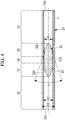
- the distance (flow channel thickness T2) from the inner peripheral surface in a region at a lower end side of the center flow channel 28 in the circumferential direction about the axis line Y, which is the circulation direction, to the outer peripheral surface thereof is shorter than the distance (flow channel thickness T1) from the inner peripheral surface in another region to the outer peripheral surface.
- a region at a lower end of the center flow channel 28 corresponds to the central portion 22a of the diaphragm 22 having thin film shape.
- the central portion 22a of the diaphragm 22 having a flat inner peripheral surface is formed on a surface (an upper surface in Fig. 11 ) of the center flow channel 28 that is located closer to the pressure sensor 12, the central portion 22a of the diaphragm 22 having a flat inner peripheral surface is formed.
- the width of the central portion 22a in the horizontal direction at each position on the axis line Y is represented by W5 and is constant.
- the thickness of the central portion 22a at each position on the axis line Y is represented by the flow channel thickness T2 and is constant.
- the center flow channel 28 includes the central portion 22a of the diaphragm 22 having a thin film shape.
- the distance (flow channel thickness T2) from the inner peripheral surface of the central portion 22a to the outer peripheral surface thereof is shorter than the distance (flow channel thickness T1) from the inner peripheral surface of each of the inflow-side end flow channel 24 and the outflow-side end flow channel 25 to the outer peripheral surface thereof.
- a part of the recess 23 formed in the inner peripheral surface of the flow channel body 21 that is located closer to the pressure sensor 12 corresponds to the diaphragm 22 in which the central portion 22a is formed into a thin film shape with the flow channel thickness T2.
- an angle formed on a horizontal plane by a pair of straight lines connecting the ends 22b of the diaphragm 22 is represented by ⁇ .
- ⁇ an angle formed on a horizontal plane by a pair of straight lines connecting the ends 22b of the diaphragm 22
- the angle ⁇ increases, an increase of the width of each end 22b per unit length of the flow channel increases. Since a change in the shape and sectional area of the flow channel 21a is small when the angle ⁇ is small, the angle ⁇ is preferably set to a small value for smooth circulation of the fluid.
- the width W5 of the central portion 22a of the diaphragm 22 in the center flow channel 28 becomes small.
- the width W5 of the central portion 22a of the diaphragm 22 is increased, it is necessary to increase the length of the flow channel of the flow channel body 21.
- An increase in the length of the flow channel of the flow channel body 21 leads to an increase in the size of the pressure detection device 100.
- the width W5 of the central portion 22a of the diaphragm 22 is set to be closer to the inner diameter of the inflow-side end flow channel 24 and the outflow-side end flow channel 25, the region having the flow channel thickness T2 can be increased.
- the width W5 increases, an increase of the width of the end 22b per unit length of the flow channel increases, which may inhibit the smooth circulation of the fluid.
- ⁇ 1, ⁇ 2, ⁇ 3, ⁇ 4, and ⁇ 5 can be arbitrarily set so as to satisfy the formulas (1) and (2). For example, values of 135° to 145°, 85° to 95°, 25° to 35°, and 15° to 25° can be adopted as the values ⁇ 1, ⁇ 2, ⁇ 3, ⁇ 4, and ⁇ 5.
- the angle formed by a pair of tangential line gradually increases toward the center flow channel 28 from the inflow-side end flow channel 24.
- the pair of end flow channels (the inflow-side end flow channel 24 and the outflow-side end flow channel 25) and the center flow channel 28 disposed at a position sandwiched between the pair of end flow channels are integrally formed of a flexible resin material. Accordingly, the flow channel body 21 included in the pressure detection device 100 of the first embodiment has no portion where a part of the portion is sealed with another member, so that a small amount of fluid does not accumulate on the sealed portion. Accordingly, even when a coagulable fluid, such as blood, is circulated, a malfunction that an accumulated and solidified fluid is recirculated through the flow channel can be prevented.
- the center flow channel 28 includes the diaphragm 22 having a thin film shape, and the diaphragm 12a is disposed in such a manner that the pressure of the fluid circulated through the flow channel 21a is transmitted via the diaphragm 22 having a thin film shape. Therefore, in the pressure detection device 100 of the first embodiment, the diaphragm 12a can appropriately detect the pressure of the fluid transmitted via the diaphragm 22 having a thin film shape.
- the pressure detection device 100 of the first embodiment it is possible to provide the pressure detection device 100 capable of detecting the pressure of the fluid circulated through the flow channel 21a, while preventing the occurrence of a malfunction due to the accumulation of the fluid in the flow channel 21a.
- the center flow channel 28 has a structure in which the distance (flow channel thickness T2) from the inner peripheral surface in a partial region of the center flow channel 28 in the circumferential direction about the axis line Y along the circulation direction is shorter than the distance (flow channel thickness T1) from the inner peripheral surface in another region to the outer peripheral surface, and the partial region is set as the central portion 22a of the diaphragm 22.
- the partial region of the center flow channel 28 in the circumferential direction can be set as a region in which a displacement due to the pressure of the fluid is more likely to occur than in the other region.
- the partial region is set as the central portion 22a of the diaphragm 22, thereby making it possible to appropriately detect the pressure of the fluid.
- the pair of connecting flow channels connects the pair of end flow channels (the inflow-side end flow channel 24 and the outflow-side end flow channel 25) and the center flow channel 28 so that the flow channel sectional area gradually increases toward the both ends of the center flow channel 28 from the pair of end flow channels. Accordingly, when the fluid is circulated from the inflow-side end flow channel 24, which is disposed at the inflow port 21b, to the center flow channel 28, the fluid does not accumulate on the flow channel 21a. Further, when the fluid is circulated from the center flow channel 28 to the outflow-side end flow channel 25 where the outflow port 24c is disposed, the fluid does not accumulate on the flow channel 21a.
- the second embodiment is a modified example of the first embodiment.
- the second embodiment is similar to the first embodiment, unless otherwise specified below, and the components of the second embodiment that are similar to those of the first embodiment are denoted by the same reference numerals as those of the first embodiment, and the descriptions thereof are omitted.
- a pressure detection device 100' of the second embodiment is different from the pressure detection device 100 of the first embodiment in that the pressure transmission portion 11 is disposed between the pressure sensor 12 and the diaphragm 22.
- a pressure detection unit 10' included in the pressure detection device 100' shown in Fig. 12 is a device that detects a pressure transmitted to the diaphragm 12a (pressure detection portion).
- the pressure detection unit 10' includes the pressure transmission portion 11 to which the pressure of the fluid from the diaphragm 22 (pressure receiving portion) of the flow channel unit 20 is transmitted; and a holding member 19 which is disposed between the pressure sensor 12 and the diaphragm 22.
- the pressure transmission portion 11 is disposed in a state where an upper end (one end) of the pressure transmission portion 11 along the axis line X is in contact with the diaphragm 12a and a lower end (the other end) thereof along the axis line X is in contact with the diaphragm 22 of the flow channel unit 20.
- the pressure transmission portion 11 transmits the fluid pressure received by the diaphragm 22 to the diaphragm 12a. Since the pressure transmission portion 11 transmits the fluid pressure to the pressure sensor 12, it is desirable that the pressure transmission portion 11 have a hardness sufficiently higher than that of the diaphragm 22. If the pressure transmission portion has a low hardness, like one used for the diaphragm 22 and the like, the pressure transmission portion serves as a damper that absorbs a pressure, which makes it difficult to measure the pressure accurately.
- the pressure transmission portion 11 includes a spherical member 11a (first pressure transmission member) disposed in contact with the diaphragm 22, and a shaft-like member 11b (second pressure transmission member) disposed in contact with the diaphragm 12a.
- An upper end face of the shaft-like member 11b is connected to the diaphragm 12a with an adhesive.
- the adhesive a material, such as glass, which is melted by heat, is used. When the adhesive is melted by heat and bonded, the adhesive is cooled and hardened. In this case, the adhesive does not serve as a buffering agent, and thus the pressure can be stably measured.
- an epoxy resin-based adhesive may be used, although the epoxy resin-based adhesive is inferior to glass with which the pressure can be stably measured and which has a high corrosion resistance.
- the spherical member 11a is a member formed into a spherical shape projecting toward the diaphragm 22 along the axis line X.
- the shaft-like member 11b is a member formed into a shaft-like shape extending along the axis line X.
- the spherical member 11a and the shaft-like member 11b are members integrally formed of, for example, metal such as aluminum, PEEK (polyether ether ketone resin), ceramics, or sapphire.
- a contact area between the upper end face of the shaft-like member 11b and the diaphragm 12a is smaller than a contact area between the spherical member 11a and the diaphragm 22.
- the holding member 19 is a member disposed between the pressure sensor 12 and the diaphragm 22 so as to hold the outer peripheral portion of the diaphragm 22, and is formed into an annular shape about the axis line X.
- one surface 19b at the lower end of the holding member 19 along the axis line X is in contact with the outer peripheral portion of the diaphragm 22, and the other surface 19a at the upper end of the holding member 19 along the axis line X is disposed in a state where the holding member 19 is in contact with the base portion 12b of the pressure sensor 12.
- the holding member 19 is provided with a vent groove 19c that communicates with an inside space S1 in a state where the pressure sensor 12 is in contact with the holding member 19.
- the body portion 13 is provided with a vent hole 13c (communication flow channel) that communicates with the vent groove 19c and an outside space S2.
- vent groove 19c and the vent hole 13c allow the inside space S1 and the outside space S2 to communicate with each other. With this structure, the inside space S1 is maintained at the same atmospheric pressure state as that in the outside space S2.
- the diaphragm 22 of the flow channel unit 20 is in contact with the spherical member 11a of the pressure transmission portion 11.
- An upper end face of the shaft-like member 11b of the pressure transmission portion 11 is connected to the diaphragm 12a.
- the diaphragm 22 is disposed on a plane orthogonal to the axis line X in the state where the pressure transmission portion 11 of the pressure sensor 12 is not contact with the diaphragm 22.
- the diaphragm 22 in the state where the pressure transmission portion 11 is in contact with the diaphragm 22, the diaphragm 22 is in a state where the inner peripheral portion of the diaphragm 22 is displaced downward along the axis line X by the pressure transmission portion 11. In the state shown in Fig. 13 , the diaphragm 22 presses the pressure transmission portion 11 upward along the axis line X by an urging force generated by elastic deformation.
- the pressure transmission portion 11 displaces the diaphragm 22 toward the flow channel 21a and is disposed in a state of receiving the urging force directed to the diaphragm 12a from the diaphragm 22.
- the diaphragm 12a can receive the pressure having a value obtained by subtracting the pressure value corresponding to the negative pressure from the pressure value equivalent to the urging force received by the pressure transmission portion 11 from the diaphragm 22.
- the pressure transmission portion 11 disposed in such a state where one end of the pressure transmission portion 11 is in contact with the diaphragm 12a of the pressure sensor 12 and the other end thereof is in contact with the diaphragm 22 of the flow channel unit 20 is disposed in a state of receiving the urging force directed to the diaphragm 12a from the diaphragm 22.
- the diaphragm 12a is in a state of receiving the pressure having a value obtained by subtracting the pressure value corresponding to the negative pressure from the pressure value equivalent to the urging force received by the pressure transmission portion 11 from the diaphragm 22.
- the diaphragm 12a can obtain the pressure value by subtracting a decrease in the pressure value due to the negative pressure from the pressure value due to the urging force received from the diaphragm 22.
- the pressure detection device 100' of the second embodiment even when the pressure of the fluid is temporarily reduced and becomes a negative pressure, the pressure of the fluid can be detected accurately.
- the pressure detection device 100' of the second embodiment includes the vent groove 19c and the vent hole 13c as a communication flow channel that communicates the inside space S1 and the outside space S2 which are partitioned by the recess 21d and the pressure sensor 12.
- the inside space S1 which is partitioned by the pressure sensor 12 and the recess 21d in which the diaphragm 22 of the flow channel unit 20 is disposed communicates with the outside space S2. Therefore, it is possible to suppress the occurrence of a malfunction that the volume of the inside space S1 fluctuates according to the displacement of the diaphragm 22 and the pressure of the inside space S1 fluctuates according to the fluctuation in the volume of the inside space S1.
- the contact area between the shaft-like member 11b and the diaphragm 12a is smaller than the contact area between the spherical member 11a and the diaphragm 22.
- the fluid pressure received by the spherical member 11a from the diaphragm 22 can be transmitted in such a manner that the fluid pressure is locally concentrated on the diaphragm 12a via the shaft-like member 11b. Therefore, the fluctuation in the pressure locally received by the diaphragm 12a is increased with respect to the fluctuation in the fluid pressure, thereby making it possible to increase the accuracy of detecting the fluctuation in the fluid pressure.
- the spherical member 11a is a member formed into a spherical shape projecting toward the diaphragm 22. Accordingly, a contact area where the spherical member 11a contacts the diaphragm 22 is maintained substantially constant, regardless of the displacement of the diaphragm 22, and thus the accuracy of transmitting the pressure of the fluid from the diaphragm 22 to the spherical member 11a can be increased.
- the pressure sensor 12 is a strain sensor that outputs a pressure signal corresponding to the strain resistance that varies depending on the pressure transmitted to the diaphragm 12a.
- the pressure sensor 12 may have another aspect.
- a capacitance pressure sensor may be used.
Landscapes
- Health & Medical Sciences (AREA)
- Vascular Medicine (AREA)
- Heart & Thoracic Surgery (AREA)
- General Physics & Mathematics (AREA)
- Physics & Mathematics (AREA)
- Engineering & Computer Science (AREA)
- Biomedical Technology (AREA)
- Anesthesiology (AREA)
- Cardiology (AREA)
- Hematology (AREA)
- Life Sciences & Earth Sciences (AREA)
- Animal Behavior & Ethology (AREA)
- General Health & Medical Sciences (AREA)
- Public Health (AREA)
- Veterinary Medicine (AREA)
- Fluid Mechanics (AREA)
- Manufacturing & Machinery (AREA)
- Mechanical Engineering (AREA)
- Measuring Fluid Pressure (AREA)
Applications Claiming Priority (1)
| Application Number | Priority Date | Filing Date | Title |
|---|---|---|---|
| JP2016019245A JP6632902B2 (ja) | 2016-02-03 | 2016-02-03 | 圧力検出装置 |
Publications (2)
| Publication Number | Publication Date |
|---|---|
| EP3203205A1 true EP3203205A1 (fr) | 2017-08-09 |
| EP3203205B1 EP3203205B1 (fr) | 2019-08-21 |
Family
ID=57960298
Family Applications (1)
| Application Number | Title | Priority Date | Filing Date |
|---|---|---|---|
| EP17154136.0A Active EP3203205B1 (fr) | 2016-02-03 | 2017-02-01 | Dispositif de détection de pression |
Country Status (4)
| Country | Link |
|---|---|
| US (1) | US9933288B2 (fr) |
| EP (1) | EP3203205B1 (fr) |
| JP (1) | JP6632902B2 (fr) |
| KR (1) | KR102604020B1 (fr) |
Cited By (2)
| Publication number | Priority date | Publication date | Assignee | Title |
|---|---|---|---|---|
| EP4533050A1 (fr) * | 2022-05-31 | 2025-04-09 | Itron Global SARL | Capteur de pression intégré dans un dispositif de mesure |
| WO2025165938A1 (fr) * | 2024-02-01 | 2025-08-07 | Repligen Corporation | Coupelle de détection de pression à membrane intégrée |
Families Citing this family (9)
| Publication number | Priority date | Publication date | Assignee | Title |
|---|---|---|---|---|
| US10391227B2 (en) * | 2014-05-15 | 2019-08-27 | Novalung Gmbh | Medico-technical measuring device and measuring method |
| US10248141B2 (en) * | 2016-05-13 | 2019-04-02 | Cameron International Corporation | Non-invasive pressure measurement system |
| WO2019083814A1 (fr) * | 2017-10-23 | 2019-05-02 | Stoneage, Inc. | Dispositif et système d'enregistreur de données pour appareil d'entraînement de lance de nettoyage à haute pression |
| JP7104415B2 (ja) * | 2018-12-10 | 2022-07-21 | サーパス工業株式会社 | 流路ユニット、圧力検出装置、および流路ユニットの製造方法 |
| JP7412731B2 (ja) * | 2019-10-02 | 2024-01-15 | サーパス工業株式会社 | 圧力検出装置 |
| US12138858B2 (en) * | 2020-05-01 | 2024-11-12 | Voltera Inc. | Systems and methods for continuous flow control of printable material in additive manufacturing |
| EP4386347A4 (fr) * | 2021-11-05 | 2025-07-23 | Hitachi High Tech Corp | Capteur de pression et dispositif de distribution |
| JP2023102906A (ja) * | 2022-01-13 | 2023-07-26 | ナブテスコ株式会社 | センサアダプタ、圧力検出システム |
| JP7822090B1 (ja) * | 2025-07-04 | 2026-03-02 | 東京計装株式会社 | 圧力検出装置における連結構造 |
Citations (3)
| Publication number | Priority date | Publication date | Assignee | Title |
|---|---|---|---|---|
| DE2419187A1 (de) * | 1974-04-20 | 1975-11-06 | Martin Dr Ing Roever | Messgeraet fuer hohe druecke, insbesondere fuer zaehfluessige und pastoese stoffe, mit einer oder mehreren beidseitig gelagerten balkenfedern als wesentliches messorgan |
| JP2005207946A (ja) | 2004-01-23 | 2005-08-04 | Surpass Kogyo Kk | インライン型圧力センサー |
| US20140076058A1 (en) * | 2011-05-31 | 2014-03-20 | Nxstage Medical, Inc. | Pressure measurement devices, methods, and systems |
Family Cites Families (15)
| Publication number | Priority date | Publication date | Assignee | Title |
|---|---|---|---|---|
| US5336051A (en) * | 1989-09-22 | 1994-08-09 | Yehuda Tamari | Inline non-invasive pressure monitoring system for pumps |
| JP4777531B2 (ja) | 2001-04-12 | 2011-09-21 | サーパス工業株式会社 | 圧力計 |
| JP2003004570A (ja) | 2001-06-18 | 2003-01-08 | Hamamatsu Koden Kk | 流体用圧力センサ |
| DE20321557U1 (de) | 2003-02-07 | 2007-12-20 | Richard Wolf Gmbh | Drucksensor für eine medizinische Schlauchpumpe |
| JP2008008706A (ja) * | 2006-06-28 | 2008-01-17 | Atsuden:Kk | ダイヤフラム圧力センサを備えた超音波流量計およびその製造方法 |
| US7421902B2 (en) * | 2006-10-13 | 2008-09-09 | Smartire Systems, Inc. | Fluid pressure sensing method and apparatus |
| WO2008071022A1 (fr) * | 2006-12-11 | 2008-06-19 | Kistler Holding Ag | Adaptateur pour capteurs de pression |
| JP2008196858A (ja) * | 2007-02-08 | 2008-08-28 | Dainippon Screen Mfg Co Ltd | 圧力センサ、差圧式流量計、流量コントローラおよび基板処理装置 |
| US7458275B2 (en) | 2007-03-15 | 2008-12-02 | Rosemount Inc. | Welded header for pressure transmitter |
| JP2009264757A (ja) * | 2008-04-22 | 2009-11-12 | Tem-Tech Kenkyusho:Kk | 管路内流体の圧力計測装置 |
| JP5058079B2 (ja) * | 2008-06-12 | 2012-10-24 | 株式会社豊田中央研究所 | 力検知センサの製造方法 |
| JP2010276534A (ja) * | 2009-05-29 | 2010-12-09 | Horiba Advanced Techno Co Ltd | 流体圧力センサ |
| US8857277B2 (en) * | 2011-09-13 | 2014-10-14 | Grand Mate Co., Ltd. | Pressure gauge and pressure detecting circuit thereof |
| US9157823B2 (en) * | 2011-09-15 | 2015-10-13 | Grand Mate Co., Ltd. | Pressure gauge and method of measuring pressure |
| JP6056562B2 (ja) * | 2013-03-08 | 2017-01-11 | 株式会社デンソー | 圧力センサおよびその製造方法 |
-
2016
- 2016-02-03 JP JP2016019245A patent/JP6632902B2/ja active Active
-
2017
- 2017-01-26 KR KR1020170012650A patent/KR102604020B1/ko active Active
- 2017-01-31 US US15/420,511 patent/US9933288B2/en active Active
- 2017-02-01 EP EP17154136.0A patent/EP3203205B1/fr active Active
Patent Citations (3)
| Publication number | Priority date | Publication date | Assignee | Title |
|---|---|---|---|---|
| DE2419187A1 (de) * | 1974-04-20 | 1975-11-06 | Martin Dr Ing Roever | Messgeraet fuer hohe druecke, insbesondere fuer zaehfluessige und pastoese stoffe, mit einer oder mehreren beidseitig gelagerten balkenfedern als wesentliches messorgan |
| JP2005207946A (ja) | 2004-01-23 | 2005-08-04 | Surpass Kogyo Kk | インライン型圧力センサー |
| US20140076058A1 (en) * | 2011-05-31 | 2014-03-20 | Nxstage Medical, Inc. | Pressure measurement devices, methods, and systems |
Cited By (2)
| Publication number | Priority date | Publication date | Assignee | Title |
|---|---|---|---|---|
| EP4533050A1 (fr) * | 2022-05-31 | 2025-04-09 | Itron Global SARL | Capteur de pression intégré dans un dispositif de mesure |
| WO2025165938A1 (fr) * | 2024-02-01 | 2025-08-07 | Repligen Corporation | Coupelle de détection de pression à membrane intégrée |
Also Published As
| Publication number | Publication date |
|---|---|
| US9933288B2 (en) | 2018-04-03 |
| EP3203205B1 (fr) | 2019-08-21 |
| US20170219395A1 (en) | 2017-08-03 |
| KR102604020B1 (ko) | 2023-11-20 |
| JP2017138202A (ja) | 2017-08-10 |
| JP6632902B2 (ja) | 2020-01-22 |
| KR20170092460A (ko) | 2017-08-11 |
Similar Documents
| Publication | Publication Date | Title |
|---|---|---|
| EP3203205B1 (fr) | Dispositif de détection de pression | |
| US9003899B2 (en) | Force sensor | |
| EP3203204A2 (fr) | Capteur de pression | |
| US6649046B2 (en) | Device for measuring negative pressures in an extracorporeal blood circuit | |
| TWI519771B (zh) | 壓力檢測器 | |
| US10422712B2 (en) | Pressure detection device and pressure sensor | |
| US10113926B2 (en) | Ceramic sensor module including diaphragm and cylindrical portion integrated with the diaphragm | |
| US20120152037A1 (en) | Force sensor | |
| US20130243032A1 (en) | Superheat Sensor | |
| US20170153157A1 (en) | Physical quantity measuring device | |
| KR102587393B1 (ko) | 통합 압력 및 온도 센서 | |
| AU2003303999A1 (en) | Pressure detector and pressure detecting method | |
| US10222286B2 (en) | Pressure detecting device having a mounting mechanism | |
| US11566958B2 (en) | Radial seal for disposable force sensor | |
| US8770010B1 (en) | Integrated detector for detecting bubbles in fluid flow and occlusions in a tube | |
| US10481028B2 (en) | Pressure detection device | |
| EP3399295A1 (fr) | Capteur de pression et son procédé de fabrication | |
| JP4734942B2 (ja) | 圧力検知装置 | |
| US11156521B2 (en) | Pressure sensor with multiple pressure sensing elements | |
| US10724910B2 (en) | Miniature size force sensor with multiple coupling technology | |
| CN221600840U (zh) | 一种压力传感器 | |
| US12366494B2 (en) | Gel-coupled pressure sensor device with interference-independent contact side for connection to an infusion hose | |
| JP2019113333A (ja) | 圧力センサー | |
| JP2003004570A (ja) | 流体用圧力センサ |
Legal Events
| Date | Code | Title | Description |
|---|---|---|---|
| PUAI | Public reference made under article 153(3) epc to a published international application that has entered the european phase |
Free format text: ORIGINAL CODE: 0009012 |
|
| STAA | Information on the status of an ep patent application or granted ep patent |
Free format text: STATUS: THE APPLICATION HAS BEEN PUBLISHED |
|
| AK | Designated contracting states |
Kind code of ref document: A1 Designated state(s): AL AT BE BG CH CY CZ DE DK EE ES FI FR GB GR HR HU IE IS IT LI LT LU LV MC MK MT NL NO PL PT RO RS SE SI SK SM TR |
|
| AX | Request for extension of the european patent |
Extension state: BA ME |
|
| STAA | Information on the status of an ep patent application or granted ep patent |
Free format text: STATUS: REQUEST FOR EXAMINATION WAS MADE |
|
| 17P | Request for examination filed |
Effective date: 20180206 |
|
| RBV | Designated contracting states (corrected) |
Designated state(s): AL AT BE BG CH CY CZ DE DK EE ES FI FR GB GR HR HU IE IS IT LI LT LU LV MC MK MT NL NO PL PT RO RS SE SI SK SM TR |
|
| STAA | Information on the status of an ep patent application or granted ep patent |
Free format text: STATUS: EXAMINATION IS IN PROGRESS |
|
| 17Q | First examination report despatched |
Effective date: 20180615 |
|
| GRAP | Despatch of communication of intention to grant a patent |
Free format text: ORIGINAL CODE: EPIDOSNIGR1 |
|
| STAA | Information on the status of an ep patent application or granted ep patent |
Free format text: STATUS: GRANT OF PATENT IS INTENDED |
|
| INTG | Intention to grant announced |
Effective date: 20190314 |
|
| GRAS | Grant fee paid |
Free format text: ORIGINAL CODE: EPIDOSNIGR3 |
|
| GRAA | (expected) grant |
Free format text: ORIGINAL CODE: 0009210 |
|
| STAA | Information on the status of an ep patent application or granted ep patent |
Free format text: STATUS: THE PATENT HAS BEEN GRANTED |
|
| AK | Designated contracting states |
Kind code of ref document: B1 Designated state(s): AL AT BE BG CH CY CZ DE DK EE ES FI FR GB GR HR HU IE IS IT LI LT LU LV MC MK MT NL NO PL PT RO RS SE SI SK SM TR |
|
| REG | Reference to a national code |
Ref country code: GB Ref legal event code: FG4D |
|
| REG | Reference to a national code |
Ref country code: CH Ref legal event code: EP |
|
| REG | Reference to a national code |
Ref country code: DE Ref legal event code: R096 Ref document number: 602017006219 Country of ref document: DE |
|
| REG | Reference to a national code |
Ref country code: CH Ref legal event code: NV Representative=s name: VALIPAT S.A. C/O BOVARD SA NEUCHATEL, CH |
|
| REG | Reference to a national code |
Ref country code: AT Ref legal event code: REF Ref document number: 1170286 Country of ref document: AT Kind code of ref document: T Effective date: 20190915 |
|
| REG | Reference to a national code |
Ref country code: IE Ref legal event code: FG4D |
|
| REG | Reference to a national code |
Ref country code: LT Ref legal event code: MG4D |
|
| REG | Reference to a national code |
Ref country code: NL Ref legal event code: MP Effective date: 20190821 |
|
| PG25 | Lapsed in a contracting state [announced via postgrant information from national office to epo] |
Ref country code: BG Free format text: LAPSE BECAUSE OF FAILURE TO SUBMIT A TRANSLATION OF THE DESCRIPTION OR TO PAY THE FEE WITHIN THE PRESCRIBED TIME-LIMIT Effective date: 20191121 Ref country code: SE Free format text: LAPSE BECAUSE OF FAILURE TO SUBMIT A TRANSLATION OF THE DESCRIPTION OR TO PAY THE FEE WITHIN THE PRESCRIBED TIME-LIMIT Effective date: 20190821 Ref country code: NO Free format text: LAPSE BECAUSE OF FAILURE TO SUBMIT A TRANSLATION OF THE DESCRIPTION OR TO PAY THE FEE WITHIN THE PRESCRIBED TIME-LIMIT Effective date: 20191121 Ref country code: NL Free format text: LAPSE BECAUSE OF FAILURE TO SUBMIT A TRANSLATION OF THE DESCRIPTION OR TO PAY THE FEE WITHIN THE PRESCRIBED TIME-LIMIT Effective date: 20190821 Ref country code: LT Free format text: LAPSE BECAUSE OF FAILURE TO SUBMIT A TRANSLATION OF THE DESCRIPTION OR TO PAY THE FEE WITHIN THE PRESCRIBED TIME-LIMIT Effective date: 20190821 Ref country code: PT Free format text: LAPSE BECAUSE OF FAILURE TO SUBMIT A TRANSLATION OF THE DESCRIPTION OR TO PAY THE FEE WITHIN THE PRESCRIBED TIME-LIMIT Effective date: 20191223 Ref country code: HR Free format text: LAPSE BECAUSE OF FAILURE TO SUBMIT A TRANSLATION OF THE DESCRIPTION OR TO PAY THE FEE WITHIN THE PRESCRIBED TIME-LIMIT Effective date: 20190821 Ref country code: FI Free format text: LAPSE BECAUSE OF FAILURE TO SUBMIT A TRANSLATION OF THE DESCRIPTION OR TO PAY THE FEE WITHIN THE PRESCRIBED TIME-LIMIT Effective date: 20190821 |
|
| PG25 | Lapsed in a contracting state [announced via postgrant information from national office to epo] |
Ref country code: AL Free format text: LAPSE BECAUSE OF FAILURE TO SUBMIT A TRANSLATION OF THE DESCRIPTION OR TO PAY THE FEE WITHIN THE PRESCRIBED TIME-LIMIT Effective date: 20190821 Ref country code: LV Free format text: LAPSE BECAUSE OF FAILURE TO SUBMIT A TRANSLATION OF THE DESCRIPTION OR TO PAY THE FEE WITHIN THE PRESCRIBED TIME-LIMIT Effective date: 20190821 Ref country code: ES Free format text: LAPSE BECAUSE OF FAILURE TO SUBMIT A TRANSLATION OF THE DESCRIPTION OR TO PAY THE FEE WITHIN THE PRESCRIBED TIME-LIMIT Effective date: 20190821 Ref country code: IS Free format text: LAPSE BECAUSE OF FAILURE TO SUBMIT A TRANSLATION OF THE DESCRIPTION OR TO PAY THE FEE WITHIN THE PRESCRIBED TIME-LIMIT Effective date: 20191221 Ref country code: RS Free format text: LAPSE BECAUSE OF FAILURE TO SUBMIT A TRANSLATION OF THE DESCRIPTION OR TO PAY THE FEE WITHIN THE PRESCRIBED TIME-LIMIT Effective date: 20190821 Ref country code: GR Free format text: LAPSE BECAUSE OF FAILURE TO SUBMIT A TRANSLATION OF THE DESCRIPTION OR TO PAY THE FEE WITHIN THE PRESCRIBED TIME-LIMIT Effective date: 20191122 |
|
| REG | Reference to a national code |
Ref country code: AT Ref legal event code: MK05 Ref document number: 1170286 Country of ref document: AT Kind code of ref document: T Effective date: 20190821 |
|
| PG25 | Lapsed in a contracting state [announced via postgrant information from national office to epo] |
Ref country code: TR Free format text: LAPSE BECAUSE OF FAILURE TO SUBMIT A TRANSLATION OF THE DESCRIPTION OR TO PAY THE FEE WITHIN THE PRESCRIBED TIME-LIMIT Effective date: 20190821 |
|
| PG25 | Lapsed in a contracting state [announced via postgrant information from national office to epo] |
Ref country code: AT Free format text: LAPSE BECAUSE OF FAILURE TO SUBMIT A TRANSLATION OF THE DESCRIPTION OR TO PAY THE FEE WITHIN THE PRESCRIBED TIME-LIMIT Effective date: 20190821 Ref country code: RO Free format text: LAPSE BECAUSE OF FAILURE TO SUBMIT A TRANSLATION OF THE DESCRIPTION OR TO PAY THE FEE WITHIN THE PRESCRIBED TIME-LIMIT Effective date: 20190821 Ref country code: IT Free format text: LAPSE BECAUSE OF FAILURE TO SUBMIT A TRANSLATION OF THE DESCRIPTION OR TO PAY THE FEE WITHIN THE PRESCRIBED TIME-LIMIT Effective date: 20190821 Ref country code: PL Free format text: LAPSE BECAUSE OF FAILURE TO SUBMIT A TRANSLATION OF THE DESCRIPTION OR TO PAY THE FEE WITHIN THE PRESCRIBED TIME-LIMIT Effective date: 20190821 Ref country code: EE Free format text: LAPSE BECAUSE OF FAILURE TO SUBMIT A TRANSLATION OF THE DESCRIPTION OR TO PAY THE FEE WITHIN THE PRESCRIBED TIME-LIMIT Effective date: 20190821 Ref country code: DK Free format text: LAPSE BECAUSE OF FAILURE TO SUBMIT A TRANSLATION OF THE DESCRIPTION OR TO PAY THE FEE WITHIN THE PRESCRIBED TIME-LIMIT Effective date: 20190821 |
|
| PG25 | Lapsed in a contracting state [announced via postgrant information from national office to epo] |
Ref country code: IS Free format text: LAPSE BECAUSE OF FAILURE TO SUBMIT A TRANSLATION OF THE DESCRIPTION OR TO PAY THE FEE WITHIN THE PRESCRIBED TIME-LIMIT Effective date: 20200224 Ref country code: SM Free format text: LAPSE BECAUSE OF FAILURE TO SUBMIT A TRANSLATION OF THE DESCRIPTION OR TO PAY THE FEE WITHIN THE PRESCRIBED TIME-LIMIT Effective date: 20190821 Ref country code: CZ Free format text: LAPSE BECAUSE OF FAILURE TO SUBMIT A TRANSLATION OF THE DESCRIPTION OR TO PAY THE FEE WITHIN THE PRESCRIBED TIME-LIMIT Effective date: 20190821 Ref country code: SK Free format text: LAPSE BECAUSE OF FAILURE TO SUBMIT A TRANSLATION OF THE DESCRIPTION OR TO PAY THE FEE WITHIN THE PRESCRIBED TIME-LIMIT Effective date: 20190821 |
|
| REG | Reference to a national code |
Ref country code: DE Ref legal event code: R097 Ref document number: 602017006219 Country of ref document: DE |
|
| PLBE | No opposition filed within time limit |
Free format text: ORIGINAL CODE: 0009261 |
|
| STAA | Information on the status of an ep patent application or granted ep patent |
Free format text: STATUS: NO OPPOSITION FILED WITHIN TIME LIMIT |
|
| PG2D | Information on lapse in contracting state deleted |
Ref country code: IS |
|
| 26N | No opposition filed |
Effective date: 20200603 |
|
| PG25 | Lapsed in a contracting state [announced via postgrant information from national office to epo] |
Ref country code: SI Free format text: LAPSE BECAUSE OF FAILURE TO SUBMIT A TRANSLATION OF THE DESCRIPTION OR TO PAY THE FEE WITHIN THE PRESCRIBED TIME-LIMIT Effective date: 20190821 |
|
| REG | Reference to a national code |
Ref country code: BE Ref legal event code: MM Effective date: 20200229 |
|
| PG25 | Lapsed in a contracting state [announced via postgrant information from national office to epo] |
Ref country code: MC Free format text: LAPSE BECAUSE OF FAILURE TO SUBMIT A TRANSLATION OF THE DESCRIPTION OR TO PAY THE FEE WITHIN THE PRESCRIBED TIME-LIMIT Effective date: 20190821 Ref country code: LU Free format text: LAPSE BECAUSE OF NON-PAYMENT OF DUE FEES Effective date: 20200201 |
|
| PG25 | Lapsed in a contracting state [announced via postgrant information from national office to epo] |
Ref country code: IE Free format text: LAPSE BECAUSE OF NON-PAYMENT OF DUE FEES Effective date: 20200201 Ref country code: FR Free format text: LAPSE BECAUSE OF NON-PAYMENT OF DUE FEES Effective date: 20200229 |
|
| PG25 | Lapsed in a contracting state [announced via postgrant information from national office to epo] |
Ref country code: BE Free format text: LAPSE BECAUSE OF NON-PAYMENT OF DUE FEES Effective date: 20200229 |
|
| GBPC | Gb: european patent ceased through non-payment of renewal fee |
Effective date: 20210201 |
|
| PG25 | Lapsed in a contracting state [announced via postgrant information from national office to epo] |
Ref country code: GB Free format text: LAPSE BECAUSE OF NON-PAYMENT OF DUE FEES Effective date: 20210201 |
|
| PG25 | Lapsed in a contracting state [announced via postgrant information from national office to epo] |
Ref country code: MT Free format text: LAPSE BECAUSE OF FAILURE TO SUBMIT A TRANSLATION OF THE DESCRIPTION OR TO PAY THE FEE WITHIN THE PRESCRIBED TIME-LIMIT Effective date: 20190821 Ref country code: CY Free format text: LAPSE BECAUSE OF FAILURE TO SUBMIT A TRANSLATION OF THE DESCRIPTION OR TO PAY THE FEE WITHIN THE PRESCRIBED TIME-LIMIT Effective date: 20190821 |
|
| PG25 | Lapsed in a contracting state [announced via postgrant information from national office to epo] |
Ref country code: MK Free format text: LAPSE BECAUSE OF FAILURE TO SUBMIT A TRANSLATION OF THE DESCRIPTION OR TO PAY THE FEE WITHIN THE PRESCRIBED TIME-LIMIT Effective date: 20190821 |
|
| REG | Reference to a national code |
Ref country code: CH Ref legal event code: U11 Free format text: ST27 STATUS EVENT CODE: U-0-0-U10-U11 (AS PROVIDED BY THE NATIONAL OFFICE) Effective date: 20260301 |
|
| PGFP | Annual fee paid to national office [announced via postgrant information from national office to epo] |
Ref country code: DE Payment date: 20260218 Year of fee payment: 10 |
|
| PGFP | Annual fee paid to national office [announced via postgrant information from national office to epo] |
Ref country code: CH Payment date: 20260301 Year of fee payment: 10 |