EP3203326A1 - Konvertierungsmechanismus für einer rotationsbewegung in jeder drehrichtung in einer bewegung mit einer einzelen bewegung richtung - Google Patents
Konvertierungsmechanismus für einer rotationsbewegung in jeder drehrichtung in einer bewegung mit einer einzelen bewegung richtung Download PDFInfo
- Publication number
- EP3203326A1 EP3203326A1 EP17151430.0A EP17151430A EP3203326A1 EP 3203326 A1 EP3203326 A1 EP 3203326A1 EP 17151430 A EP17151430 A EP 17151430A EP 3203326 A1 EP3203326 A1 EP 3203326A1
- Authority
- EP
- European Patent Office
- Prior art keywords
- conversion mechanism
- mobile
- mechanism according
- axis
- eccentric
- Prior art date
- Legal status (The legal status is an assumption and is not a legal conclusion. Google has not performed a legal analysis and makes no representation as to the accuracy of the status listed.)
- Granted
Links
Images


Classifications
-
- G—PHYSICS
- G04—HOROLOGY
- G04B—MECHANICALLY-DRIVEN CLOCKS OR WATCHES; MECHANICAL PARTS OF CLOCKS OR WATCHES IN GENERAL; TIME PIECES USING THE POSITION OF THE SUN, MOON OR STARS
- G04B5/00—Automatic winding up
- G04B5/02—Automatic winding up by self-winding caused by the movement of the watch
- G04B5/10—Automatic winding up by self-winding caused by the movement of the watch by oscillating weights the movement of which is not limited
- G04B5/14—Automatic winding up by self-winding caused by the movement of the watch by oscillating weights the movement of which is not limited acting in both directions
-
- G—PHYSICS
- G04—HOROLOGY
- G04B—MECHANICALLY-DRIVEN CLOCKS OR WATCHES; MECHANICAL PARTS OF CLOCKS OR WATCHES IN GENERAL; TIME PIECES USING THE POSITION OF THE SUN, MOON OR STARS
- G04B11/00—Click devices; Stop clicks; Clutches
- G04B11/006—Clutch mechanism between two rotating members with transfer of movement in only one direction (free running devices)
-
- G—PHYSICS
- G04—HOROLOGY
- G04B—MECHANICALLY-DRIVEN CLOCKS OR WATCHES; MECHANICAL PARTS OF CLOCKS OR WATCHES IN GENERAL; TIME PIECES USING THE POSITION OF THE SUN, MOON OR STARS
- G04B11/00—Click devices; Stop clicks; Clutches
- G04B11/006—Clutch mechanism between two rotating members with transfer of movement in only one direction (free running devices)
- G04B11/008—Clutch mechanism between two rotating members with transfer of movement in only one direction (free running devices) with friction members, e.g. click springs or jumper
Definitions
- the present invention relates to a conversion clock mechanism for converting a rotary motion of any amplitude and direction into a unidirectional rotary motion.
- the winding of the mainspring or mainspring is effected by means of a mass which oscillates under the effect of the movements of the wearer of the watch.
- the force generated by the oscillations of the mass is communicated to the winding ratchet of the mainspring by a gear reducer.
- Some automatic winding mechanisms comprise, between the oscillating weight and the gear train, a device called “inverter” allowing the gear train to rotate in the direction causing the winding of the mainspring irrespective of the direction of rotation. of the oscillating mass.
- inverter A particularly advantageous type of this inverter device, in terms of simplicity, efficiency and bulk, is known as the "Pellaton system" and described in US Pat. DE882227 .
- the Pellaton system comprises a cam secured to the oscillating mass, a rocker cooperating with the cam via two rollers, and two pawls mounted on the rocker.
- the respective beaks of the pawls are held in contact, by a spring acting between the pawls, with the toothing of a wolf-tooth wheel connected to the winding ratchet by means of the gear wheel.
- these two pawls alternately advance the wolf wheel. Variations of this mechanism have been described in the patent US3846973 and in patent applications JP 2003130967 and JP 2003279666
- the document CH242384 discloses a timepiece with automatic winding and by hand, in which a ratchet and a transmission member of the automatic winding device each drive the barrel shaft via a freewheel clutch, the two clutches with freewheel being arranged so that the ratchet and said automatic winding member act independently of one another.
- the invention relates to a conversion mechanism comprising a first mobile drivable according to any rotary movement, a second mobile, and a transmission member cooperating with the first and the second mobile; the first mobile comprising a board pivoting about an axis and a guide member, the latter being configured to drive the transmission member eccentrically relative to the axis; the second mobile having a clutch member; the transmission member intermittently cooperating with the clutch member by intermittently to drive the second movable in a unidirectional rotary motion.
- the bracing uses a principle of jamming in one direction, which allows us to make a clutch in one direction, the direction of jamming, the other direction releasing the moving part, an eccentric for example, of this position bracing.
- the invention also relates to an automatic winding mechanism of a timepiece comprising the conversion mechanism of the invention and a watch comprising such a mechanism for automatic winding.
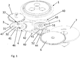
- the figure 1 represents a conversion mechanism for a watch application, according to one embodiment.
- the mechanism comprises a first mobile 3 drivable according to any rotary movement (for example bidirectional), a second mobile 5, and a transmission member 4 cooperating with the first and the second mobile 3, 5.
- the first mobile 3 comprises a board 31 pivoting about an axis of rotation 33 and a guide member 32.
- the guide member 32 is configured to drive the transmission member 4 eccentrically relative to the axis 33.
- the second mobile 5 comprises a board 52, or toothed wheel, driving a clutch member 51. Note that the rotary movement of the first mobile 3 can be unidirectional or bidirectional.
- the first mobile 3, the board 31 and the guide member 32 may consist of a single piece.
- the conversion mechanism is included in an automatic winding mechanism of a watch comprising an oscillating weight.
- a ball bearing suspension 1 is shown.
- An intermediate mobile leading 2 is engaged with a pinion (not shown) integral with the suspension 1.
- the intermediate driving mobile 2 is also engaged with the board 31 of the first mobile 3 (or moving mobile) so that the rotational movement of the oscillating mass is transmitted to the first mobile 3 through the intermediate mobile leading 2.
- the automatic winding mechanism also comprises an intermediate mobile led 6 engaged with the board 52 of the second mobile 5 (or driven mobile) and with a barrel ratchet 7.
- the first mobile 3 can be mounted coaxial with the pivot axis of the oscillating mass, in which case the intermediate driving mobile 2 is not required.
- the transmission member 4 cooperates with the second mobile 5 through the clutch member 51 intermittently, so as to drive the second mobile 5 in a unidirectional rotary motion.
- the oscillating mass drives, through the intermediate driving mobile 2, the first mobile 3 in rotation in both directions according to the rotation of the oscillating mass.
- the oscillating mass pivoting freely in both directions drives the barrel ratchet 7, via the second mobile 5 and the driven intermediate wheel 6, in a single direction to arm the barrel spring (not shown). .
- the transmission member 4 comprises two levers 42 extending from the guiding member 32 and is terminated by a locking member 40.
- the locking member 40 of each of the levers 42 cooperates alternately with the clutch member 51 when the transmission member 4 cooperates with the second mobile unit 5.
- the locking member 40 comprises a mobile element 44 cooperating by jamming, locking or friction with the clutch member 51 when the transmission member 4 cooperates with the second mobile 5.
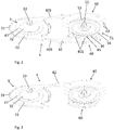
- the figure 2 shows an isolated view of the transmission member 4 and the clutch member 51.
- the clutch member 51 comprises a bearing ring 53 provided with a raceway 54.
- the locking member 40 takes the form of a portion of a ball bearing comprising two housings 45, each housing being configured as a cage portion.
- the movable element comprises a ball 44 held in the housing 45.
- the housing 45 has an inclined plane 401 so that, when the locking member 40 cooperates with the raceway 54, the ball 44 gets stuck between the path bearing 54 and the inclined plane 401 of the housing 45.
- the inclined plane 401 may be rectilinear or curvilinear.
- the locking member 40 can thus drive the second mobile 5.
- one of the locking members 40 is shown "closed”, that is to say with a support cage 43 enclosing the housings 45 and the balls 44.
- the other locking member 40 is shown "open", c ' that is to say without the support cage 43 allowing to see the housings 45 and the balls 44.
- the locking member 40 may comprise a different number of housings 45 and balls 44.
- the movable member 44 may also include rollers or other suitable element instead of balls. Note also that a single ball 44 or a single friction cylinder (or roll) by locking member 40 may be sufficient if the movable member 44 is completed by a friction ratchet (for example mounted on a watch frame) which retains the second mobile 5 in the direction of disengagement.
- the transmission member 4 and the guide member 32 are configured so that the locking member 40 of each of the levers 42 cooperates with the clutch member 51 intermittently and alternately driving the second mobile 5 in one direction and avoiding a rotation of the second mobile 5 in the opposite direction.
- the plate 52 of the second mobile 5 may be engaged with a pinion (not shown) coaxial with the bearing ring 53 (as illustrated in FIG. figure 1 ) or be pivotally mounted on the same axis 55 as that of the bearing ring 53.
- the guide member comprises a hinge member 32 integral with the board 31 of the first moving part 3 and eccentric with respect to the axis of rotation 33.
- the hinge member 32 serves to guide a rocker 41 on which are fixed the levers 42.
- the hinge member may comprise a bearing (or pivot) 32 secured to the first mobile 3 and eccentric with respect to the axis of rotation 33 of the first mobile.
- the latch 41 may comprise a bore 46 freely engaging around the pivot 32. In this configuration, each of the levers operate in a manner similar to a rod articulated from the pivot 32.
- a bearing 47 can be inserted between the pivot 32 and the circular bore 46 so as to reduce the friction between the latch 41 and the pivot 32.
- the levers 42 comprise a flexible portion 409 (see FIG. figure 2 ) can play a role of virtual pivot connecting the latch 41 to the clutch member 40.
- the hinge member comprises a cam mounted concentrically with the axis 33 and whose radius is variable relative to the axis 33.
- the latch 41 may be guided by the cam.
- Variable-radius cam means any cam of any geometry, such as for example an eccentric, an Archimedes spiral core, a Reuleux cam, a polygon, etc.
- the figure 3 illustrates the conversion mechanism according to a variant, wherein the transmission member 4 comprises a single lever 42 extending from the latch 41 and is terminated by the locking member 40.
- the single locking member 40 cooperates intermittently with the clutch member 51 and drives the second mobile 5.
- a fixed locking member 60 prevents the second mobile 5 pivots in the opposite direction to that in which it is driven by the transmission member 4 when the locking member 40 is not in cooperation with the clutch member 51.
- the fixed locking member 60 comprises two housings 45, each comprising a ball 45, as illustrated in FIGS. figures 1 and 2 .
- the fixed locking member 60 may be attached to a frame of the watch or may be mounted on a second latch which is stationary while the first latch is movable.
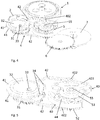
- the figure 4 shows the conversion mechanism again according to another embodiment.
- the figure 5 shows a perspective view and the figure 6 shows a view from above of the transmission member 4 and the second mobile 5 according to the configuration of the figure 4 .
- the transmission member 4 comprises two latches 41 each having a lever 42.
- the two latches 41 are mounted coaxially on a joint member 32 (pivot) common eccentric with respect to the axis 33 of rotation of the first mobile 3.
- L hinge member 32 guides the two latches and their respective lever 42 in a movement similar to that of a connecting rod so that the locking member 40 of each of the levers 42 cooperates alternately with the clutch member 51 when the transmission member 4 is driven by the first mobile 3.
- the two latches can be made integral with each other, for example with the help of the fingers 34.
- the locking member 40 comprises a latch 403 itself pivotally mounted on a pivot 402 at the end of each lever 42 and on the axis 55 of the bearing ring 53.
- the movement of the levers 42 driven by the first mobile 3 rotates the locking member 40 so that each of the two locking members 40 cooperates alternately and drives the second mobile 5.
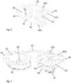
- the figure 7 illustrates a variant of the conversion mechanism of Figures 4 and 5 comprising a single latch 41 having a lever 42.
- the conversion mechanism also comprises a fixed locking element 60 configured as in the example of FIG. figure 3 .
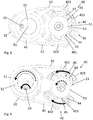
- FIGs 8 to 10 show the operation of the conversion mechanism according to the configuration of Figures 4 to 6 .
- figure 8 shows the conversion mechanism in an initial position.
- the figure 9 shows the conversion mechanism in an initial position.
- the figure 9 shows the conversion mechanism when the hinge member 32, guided by the axis 33, is rotated 90 ° counterclockwise with respect to the initial position.
- the levers 42 pivots a latch 403 counterclockwise forcing the balls 44 to be housed in the narrow part of the housing 45 and jam between the inclined plane of the housing 401, so that the locking member 40 cooperates with the clutch member 51 by bracing and driving in a counterclockwise rotational movement.
- the other latch 403 'pivots clockwise so that the balls 44 are in the wide part of the housing 45 and can freely roll in the housing 45.
- Figures 8 to 10 the direction of rotation of the driving members (the axis 33 and the locking members 40) is indicated by the solid arrows and the direction of rotation of the driven members (the hinge member 32 and the clutch member 51 ) is indicated by the dashed arrows.
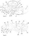
- the figure 10 shows the conversion mechanism when the hinge member 32 is rotated 270 ° counterclockwise from the initial position.
- the latch 403 pivots clockwise and the balls 44 roll freely in the wide part of the housing 45.
- the latch 403 'pivots counterclockwise forcing the balls 44 to be housed in the narrow part of the housing 45 of so that the locking member 40 drives the clutch member 51 in a counterclockwise rotational movement.
- the figure 11 represents the conversion mechanism according to another embodiment and the figure 12 shows a perspective view and the figure 13 shows a view from above of the transmission member 4 and the second mobile 5 according to the configuration of the figure 11 .
- the transmission member 4 comprises a latch 41 comprising two levers 42.
- the latch 41 is guided by a pivot 32 integral with the first mobile 3 and eccentric with respect to the axis of rotation 33 of the first mobile 3, as in the configuration of FIG. the figure 1 .
- the locking member 40 comprises two unidirectional ball bearings 43, 43 ', each of the bearings being pivotally guided on a pivot 402 at the end of a lever 42.
- Each of the bearings 43, 43' comprises a coaxial outer ring with an inner ring and a cage.
- the cage having dwellings having an inclined plane (the rings, the cage and the housings are not visible on the Figures 11 to 13 ).
- the coupling between the outer and inner rings of the bearing is made in a single direction of rotation of the bearing, when the balls are jammed by wedging between the outer ring and the housing walls.
- the second mobile 5 In the case where the second mobile 5 is secured to the second mobile 5, for example via the axis 55 of the second mobile, the second mobile 5 will be rotated by one of the two bearings 43, 43 'rotating in one direction (for example, counterclockwise, as indicated by the arrows in the Figures 11 to 13 ) and will be in free rotation with the other bearings 43, 43 'rotating in the opposite direction.
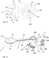
- the figure 14 represents the conversion mechanism according to another embodiment in which the clutch member 51 comprises a disc 57 pivotally concentric with the axis 55 of a pinion 52 'of second mobile 5, the pinion 52' being intended to mesh with the plate 52 of second mobile 5.
- the transmission member 4 comprises two latches 41, each having a lever 42.
- the two latches 41 are each mounted on a pivot 32excentré relative to the axis 33 of rotation of the first mobile (not represented on the figure 14 ).
- Each of the levers 42 is terminated by a blocking member support 404 having a locking member (eccentric blocking) 406 having a variable radius.
- the locking eccentric is guided by a pin 407.
- the configuration of the transmission member 4 is such that the element supports of block 404 are arranged on each side of the disk 57.
- the locking eccentric 406 come into contact with the wafer 57 'of the disk 57 alternatively with the wafer 57 57 of the disk 57 so that, in the direction of driving of the levers 42, each of the locking eccentric 406 pivots and jams against the disk 57 by bracing.
- the second mobile 5 is thus driven in a single direction.
- the cams 33 of the latches are ideally eccentric to each other, with a phase shift between their respective centers relative to the center of the pivot 32 from 0 ° to 180 °.
- each lever 42 has a flexible bend 405, ie a virtual pivot, for guiding the blocking member supports 404 so as to maintain the locking eccentric members 406 in contact with the wafer 57 'of the disk 57 when the blocking member 40 cooperates with the second mobile 5.
- the locking eccentric 406 can be kept in contact against the wafer 57 'when the locking member 40 cooperates with the clutch member 51 by means of a spring 408, integrated in the locking eccentric 406 in this configuration.
- the figure 15 illustrates the conversion mechanism of the figure 11 according to another variant in which the locking eccentric 406 is separated from the return spring 408.
- the locking eccentric comprises a cam 406 pivotally mounted on a pivot 407.
- the figure 16 shows a variant of the conversion mechanism of the figure 15 , in which the transmission member 4 comprises a single latch 41 and a single lever 42 having a locking eccentric 406 with its return spring 408.
- a fixed locking member 60 prevents the second mobile 5 from pivoting in the direction opposite to that in which it is driven by the transmission member 4 when the locking member 40 is not in cooperation with the clutch member 51.
- the fixed locking element 60 comprises a cam 606 pivoting about a pivot 607 and kept in contact with the slice 57 'of the disk 57 by means of a return spring 608.
- the cam 606 can be mounted on a frame of a watch movement.
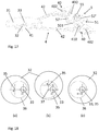
- the figure 17 shows a variant of the conversion mechanism in which the latter is produced with a reduced number of parts, in particular by the combination of eccentric guide functions input, transmission of movement by an arm, pivot function of this arm by flexible element and arc- stop against the receiving disc in one and the same room.
- the proposed assembly could, however, as in some previous versions be made on two levels to separate two rods.
- the bracing is always carried out on a member movable in rotation about a virtual pivot, this pivot being preferably a fixed pivot relative to a reference frame of the arm supporting it. In order to ensure the precise guidance of the two clutches around the clutch disc, they can be guided by an arm mobile in rotation about the axis of the output mobile.
- the transmission member 4 comprises two levers 42, each extending from a rocker 41 pivotally mounted on the guide member 32, and terminated by a locking member 40.
- the clutch member 51 comprises a disc 57 (only half of the disc is represented in the figure 17 ) pivoting concentrically with the axis 55 of a pinion 52 'of the second mobile 5.
- Each of the locking members 40 comprises a flexible element 410 adapted to bear against the wafer 57' of the disk 57 in a bracing relationship .
- the flexible element 410 is formed in one piece with the lever 42 and the latch 41.
- the bracing is obtained by the fact that each of the levers 42 is pivotally mounted on a mobile element 501 in rotation around the common axis 55 of the pinion 52 'and the disc 57, via a pivot 402.
- the eccentricity of the transmission member 4 is defined by the distance between the axis of rotation 33 of the first mobile 3 and the center 35 of the guide member 32 (see, for example, FIG. figure 8 ).
- the organ of guide 32 includes a second eccentric member 36 movable relative to the guide member 32.
- the second eccentric member 36 can be rotated about the center 37 of the opening of the 32.
- the figure 18a shows the second eccentric element 36 arranged to maximize the eccentricity, that is to say a maximum distance between the axis of rotation 33 (A) of the first mobile 3 and the center 35 (B) of the organ 32.
- this distance AB is zero and the maximum distance between the axis of rotation 33 of the first mobile 3 and the center 35 of the guide member 32 is zero.
- the pivoting of the second eccentric element 36 results in an eccentricity (distance AB) intermediate.
- the boundary between the second eccentric member 36 and the guide member 32 may be continuous as illustrated in FIGS. Figures 18a to 18c , allowing a continuous adjustment of the degree of eccentricity.
- the boundary between the second eccentric member 36 and the guide member 32 may also have a non-continuous interface, for example fluted or faceted, as illustrated by FIG. figure 18d , allowing an adjustment of the degree of eccentricity in steps, or have any other suitable form.
- the variation of the degree of eccentricity of the transmission member 4 makes it possible to vary the transmission speed / torque parameters of the conversion mechanism.
- the variation of the degree of eccentricity of the transmission member 4 makes it possible to adapt the conversion mechanism of the invention to calibres of watches with different characteristics (winding speed, torque of the mainspring, etc.). It also makes it possible to adapt the conversion mechanism to extreme winding conditions of the watch, for example in the case of wearing too dynamically or, on the contrary, too static, and therefore to the winding conditions defined by their wearer. It also makes it possible to adapt the conversion mechanism to the winding parameters to any other situation that may require its application.
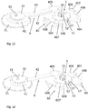
- the clutch member 51 is arranged to pivot slightly eccentrically with respect to the axis of rotation 55 of the second mobile 5.
- the figure 19 shows an example where the locking member 40 takes the form of a portion of a ball bearing, where the ball 44 is wedged between the bearing ring 53 and the slope of the cage 45, this slope can be linear or curvilinear.
- the figure 20 shows an example where the locking member 40 comprises a locking eccentric 406.
- the eccentricity is illustrated by the dotted line in the figures.
- the eccentricity has the effect that the locking / friction of the movable member 44 (locking eccentric 406, etc.) is distributed over a larger portion of the surface of the cage member 45.
- the occurrence of repeated contacts In this case, the blocking / frictional engagement at the same points on the surface can be significantly reduced compared with a configuration where the clutch member 53, 57 pivots concentrically with respect to the axis of rotation 55. wear due to the pressures on the cage member 45 are minimized.
- Such an arrangement can be achieved without disturbing the winding parameters significantly (in the case where the conversion mechanism is used in a mechanism for automatic winding a watch).
- Another way of distributing the stresses and the wear on different portions of the locking eccentric 406 or of the cage element 45 consists in using a clutch disc 53 concentric with its center of rotation 55, giving to said clutch disk 53 a slightly oval shape, for example of ellipsoidal type, or any other geometry slightly varying the distance defined between the point of contact with the locking element 406, 44 and the center of rotation 55.
- the automatic conversion mechanism can also be used in any other transmission device that requires the conversion of bidirectional motion into unidirectional motion.
Landscapes
- Physics & Mathematics (AREA)
- General Physics & Mathematics (AREA)
- Transmission Devices (AREA)
Applications Claiming Priority (1)
| Application Number | Priority Date | Filing Date | Title |
|---|---|---|---|
| CH1462016 | 2016-02-04 |
Publications (2)
| Publication Number | Publication Date |
|---|---|
| EP3203326A1 true EP3203326A1 (de) | 2017-08-09 |
| EP3203326B1 EP3203326B1 (de) | 2020-03-04 |
Family
ID=55304801
Family Applications (1)
| Application Number | Title | Priority Date | Filing Date |
|---|---|---|---|
| EP17151430.0A Active EP3203326B1 (de) | 2016-02-04 | 2017-01-13 | Konvertierungsmechanismus für einer rotationsbewegung in jeder drehrichtung in einer bewegung mit einer einzelen bewegung richtung. |
Country Status (1)
| Country | Link |
|---|---|
| EP (1) | EP3203326B1 (de) |
Cited By (2)
| Publication number | Priority date | Publication date | Assignee | Title |
|---|---|---|---|---|
| EP3926411A1 (de) * | 2020-06-16 | 2021-12-22 | Damasko Präzisionstechnik GmbH & Co. KG | Automatischer aufzugsmechanismus mit dezentralem wälzlager |
| US20220187767A1 (en) * | 2020-12-16 | 2022-06-16 | Manufacture D'horlogerie Audemars Piguet Sa | Transmission mechanism for a horological movement |
Citations (8)
| Publication number | Priority date | Publication date | Assignee | Title |
|---|---|---|---|---|
| CH242384A (fr) | 1945-12-18 | 1946-05-15 | Tissot Horlogerie | Pièce d'horlogerie à remontage automatique et à la main. |
| DE882227C (de) | 1950-06-07 | 1953-07-06 | Ernest Homberger Rauschenbach | Selbsttaetige Aufziehvorrichtung mit Schwungmasse fuer Remontoiruhrwerke (Armbanduhren) |
| US3846973A (en) | 1970-12-28 | 1974-11-12 | Suwa Seikosha Kk | Automatic winding watch with bridge plate offset to receive automatic winding mechanism |
| JP2003130967A (ja) | 1999-09-29 | 2003-05-08 | Seiko Epson Corp | 計時装置 |
| JP2003279666A (ja) | 2002-03-25 | 2003-10-02 | Seiko Epson Corp | 時 計 |
| DE102008051197A1 (de) * | 2008-10-14 | 2010-04-15 | Konrad Damasko | Mechanischer Federaufzug für die Antriebsfeder von Armbanduhren sowie Armbanduhr mit einem derartigen Aufzug |
| WO2012150492A1 (fr) * | 2011-05-03 | 2012-11-08 | Patek Philippe Sa Geneve | Mécanisme de remontage automatique |
| EP2634650A2 (de) * | 2012-02-29 | 2013-09-04 | Richemont International S.A. | Automatischer bidirektionaler Aufziehmechanismus für Uhrwerk |
-
2017
- 2017-01-13 EP EP17151430.0A patent/EP3203326B1/de active Active
Patent Citations (8)
| Publication number | Priority date | Publication date | Assignee | Title |
|---|---|---|---|---|
| CH242384A (fr) | 1945-12-18 | 1946-05-15 | Tissot Horlogerie | Pièce d'horlogerie à remontage automatique et à la main. |
| DE882227C (de) | 1950-06-07 | 1953-07-06 | Ernest Homberger Rauschenbach | Selbsttaetige Aufziehvorrichtung mit Schwungmasse fuer Remontoiruhrwerke (Armbanduhren) |
| US3846973A (en) | 1970-12-28 | 1974-11-12 | Suwa Seikosha Kk | Automatic winding watch with bridge plate offset to receive automatic winding mechanism |
| JP2003130967A (ja) | 1999-09-29 | 2003-05-08 | Seiko Epson Corp | 計時装置 |
| JP2003279666A (ja) | 2002-03-25 | 2003-10-02 | Seiko Epson Corp | 時 計 |
| DE102008051197A1 (de) * | 2008-10-14 | 2010-04-15 | Konrad Damasko | Mechanischer Federaufzug für die Antriebsfeder von Armbanduhren sowie Armbanduhr mit einem derartigen Aufzug |
| WO2012150492A1 (fr) * | 2011-05-03 | 2012-11-08 | Patek Philippe Sa Geneve | Mécanisme de remontage automatique |
| EP2634650A2 (de) * | 2012-02-29 | 2013-09-04 | Richemont International S.A. | Automatischer bidirektionaler Aufziehmechanismus für Uhrwerk |
Cited By (5)
| Publication number | Priority date | Publication date | Assignee | Title |
|---|---|---|---|---|
| EP3926411A1 (de) * | 2020-06-16 | 2021-12-22 | Damasko Präzisionstechnik GmbH & Co. KG | Automatischer aufzugsmechanismus mit dezentralem wälzlager |
| US20220187767A1 (en) * | 2020-12-16 | 2022-06-16 | Manufacture D'horlogerie Audemars Piguet Sa | Transmission mechanism for a horological movement |
| CN114637177A (zh) * | 2020-12-16 | 2022-06-17 | 爱彼制表公司 | 用于钟表机芯的传动机构 |
| US12314009B2 (en) | 2020-12-16 | 2025-05-27 | Manufacture D'horlogerie Audemars Piguet Sa | Transmission mechanism for a horological movement |
| CN114637177B (zh) * | 2020-12-16 | 2026-08-07 | 爱彼制表公司 | 用于钟表机芯的传动机构 |
Also Published As
| Publication number | Publication date |
|---|---|
| EP3203326B1 (de) | 2020-03-04 |
Similar Documents
| Publication | Publication Date | Title |
|---|---|---|
| EP1843225B1 (de) | Mechanischer Wechsler zum Drehantreiben eines Rades aus einer einzelnen Richtung | |
| EP3158401B1 (de) | Übertragungsvorrichtung für uhr | |
| CH706701B1 (fr) | Mécanisme de remontage automatique. | |
| FR2566868A1 (fr) | Reducteur epicycloidal a blocage centrifuge | |
| EP2677372A1 (de) | Rad mit Spielnachstellung | |
| EP3203326B1 (de) | Konvertierungsmechanismus für einer rotationsbewegung in jeder drehrichtung in einer bewegung mit einer einzelen bewegung richtung. | |
| FR3009049A1 (fr) | Disque d'embrayage pour embrayage a friction | |
| EP2313812B1 (de) | Uhrwerk mit integrierter automatischer aufzugvorrichtung | |
| FR3009048A1 (fr) | Disque d'embrayage pour embrayage a friction | |
| EP3208663B1 (de) | Kugellager und anschlusssystem, das ein solches kugellager umfasst | |
| EP3376308B1 (de) | Aufziehmechanismus einer uhr | |
| EP2244138B1 (de) | Vorrichtung zum Aufziehen einer automatischen Armbanduhr, die mit einem Auskupplungssystem versehen ist | |
| CH713407B1 (fr) | Système de remontage pour pièce d'horlogerie. | |
| CH719508A9 (fr) | Mécanisme de force constante. | |
| CH707741B1 (fr) | Mécanisme de remontage automatique. | |
| EP4016192A1 (de) | Übertragungsmechanismus für uhrwerk | |
| EP3969964B1 (de) | Uhrwerk einer armbanduhr mit automatischem aufzug | |
| EP3783444B1 (de) | Uhrwerkmechanismus, der eine blockiervorrichtung umfasst | |
| EP3561604A1 (de) | Uhrreglermechanismus mit über gelenke verbundenen resonatoren | |
| EP4375758A2 (de) | Getriebemechanismus für eine automatische aufzugsvorrichtung | |
| WO2018100313A1 (fr) | Moyen d'agrippement autobloquant d'un système de transmission continument variable | |
| CH713582A2 (fr) | Mécanisme de remontage d'une pièce d'horlogerie. | |
| CH717664B1 (fr) | Pièce d'horlogerie comprenant un dispositif de commande étanche. | |
| FR3136266A3 (fr) | Dispositif et procédé d’embrayage unidirectionnel | |
| EP4312083A1 (de) | Kupplungs-ausrückvorrichtung für uhr |
Legal Events
| Date | Code | Title | Description |
|---|---|---|---|
| PUAI | Public reference made under article 153(3) epc to a published international application that has entered the european phase |
Free format text: ORIGINAL CODE: 0009012 |
|
| STAA | Information on the status of an ep patent application or granted ep patent |
Free format text: STATUS: THE APPLICATION HAS BEEN PUBLISHED |
|
| AK | Designated contracting states |
Kind code of ref document: A1 Designated state(s): AL AT BE BG CH CY CZ DE DK EE ES FI FR GB GR HR HU IE IS IT LI LT LU LV MC MK MT NL NO PL PT RO RS SE SI SK SM TR |
|
| AX | Request for extension of the european patent |
Extension state: BA ME |
|
| STAA | Information on the status of an ep patent application or granted ep patent |
Free format text: STATUS: REQUEST FOR EXAMINATION WAS MADE |
|
| 17P | Request for examination filed |
Effective date: 20180108 |
|
| RBV | Designated contracting states (corrected) |
Designated state(s): AL AT BE BG CH CY CZ DE DK EE ES FI FR GB GR HR HU IE IS IT LI LT LU LV MC MK MT NL NO PL PT RO RS SE SI SK SM TR |
|
| RIC1 | Information provided on ipc code assigned before grant |
Ipc: G04B 5/14 20060101AFI20180503BHEP Ipc: G04B 11/00 20060101ALI20180503BHEP |
|
| STAA | Information on the status of an ep patent application or granted ep patent |
Free format text: STATUS: EXAMINATION IS IN PROGRESS |
|
| 17Q | First examination report despatched |
Effective date: 20180809 |
|
| GRAP | Despatch of communication of intention to grant a patent |
Free format text: ORIGINAL CODE: EPIDOSNIGR1 |
|
| STAA | Information on the status of an ep patent application or granted ep patent |
Free format text: STATUS: GRANT OF PATENT IS INTENDED |
|
| RIN1 | Information on inventor provided before grant (corrected) |
Inventor name: SIGRIST, MARTIN Inventor name: LECHOT, CHRISTOPHE Inventor name: BONNARDIN, MATHIEU Inventor name: KRESS, JEREMY |
|
| INTG | Intention to grant announced |
Effective date: 20190924 |
|
| GRAS | Grant fee paid |
Free format text: ORIGINAL CODE: EPIDOSNIGR3 |
|
| GRAA | (expected) grant |
Free format text: ORIGINAL CODE: 0009210 |
|
| STAA | Information on the status of an ep patent application or granted ep patent |
Free format text: STATUS: THE PATENT HAS BEEN GRANTED |
|
| AK | Designated contracting states |
Kind code of ref document: B1 Designated state(s): AL AT BE BG CH CY CZ DE DK EE ES FI FR GB GR HR HU IE IS IT LI LT LU LV MC MK MT NL NO PL PT RO RS SE SI SK SM TR |
|
| REG | Reference to a national code |
Ref country code: GB Ref legal event code: FG4D Free format text: NOT ENGLISH |
|
| REG | Reference to a national code |
Ref country code: CH Ref legal event code: EP |
|
| REG | Reference to a national code |
Ref country code: AT Ref legal event code: REF Ref document number: 1241105 Country of ref document: AT Kind code of ref document: T Effective date: 20200315 |
|
| REG | Reference to a national code |
Ref country code: DE Ref legal event code: R096 Ref document number: 602017012424 Country of ref document: DE |
|
| REG | Reference to a national code |
Ref country code: IE Ref legal event code: FG4D Free format text: LANGUAGE OF EP DOCUMENT: FRENCH |
|
| PG25 | Lapsed in a contracting state [announced via postgrant information from national office to epo] |
Ref country code: RS Free format text: LAPSE BECAUSE OF FAILURE TO SUBMIT A TRANSLATION OF THE DESCRIPTION OR TO PAY THE FEE WITHIN THE PRESCRIBED TIME-LIMIT Effective date: 20200304 Ref country code: FI Free format text: LAPSE BECAUSE OF FAILURE TO SUBMIT A TRANSLATION OF THE DESCRIPTION OR TO PAY THE FEE WITHIN THE PRESCRIBED TIME-LIMIT Effective date: 20200304 Ref country code: NO Free format text: LAPSE BECAUSE OF FAILURE TO SUBMIT A TRANSLATION OF THE DESCRIPTION OR TO PAY THE FEE WITHIN THE PRESCRIBED TIME-LIMIT Effective date: 20200604 |
|
| REG | Reference to a national code |
Ref country code: NL Ref legal event code: MP Effective date: 20200304 |
|
| PG25 | Lapsed in a contracting state [announced via postgrant information from national office to epo] |
Ref country code: HR Free format text: LAPSE BECAUSE OF FAILURE TO SUBMIT A TRANSLATION OF THE DESCRIPTION OR TO PAY THE FEE WITHIN THE PRESCRIBED TIME-LIMIT Effective date: 20200304 Ref country code: GR Free format text: LAPSE BECAUSE OF FAILURE TO SUBMIT A TRANSLATION OF THE DESCRIPTION OR TO PAY THE FEE WITHIN THE PRESCRIBED TIME-LIMIT Effective date: 20200605 Ref country code: LV Free format text: LAPSE BECAUSE OF FAILURE TO SUBMIT A TRANSLATION OF THE DESCRIPTION OR TO PAY THE FEE WITHIN THE PRESCRIBED TIME-LIMIT Effective date: 20200304 Ref country code: BG Free format text: LAPSE BECAUSE OF FAILURE TO SUBMIT A TRANSLATION OF THE DESCRIPTION OR TO PAY THE FEE WITHIN THE PRESCRIBED TIME-LIMIT Effective date: 20200604 Ref country code: SE Free format text: LAPSE BECAUSE OF FAILURE TO SUBMIT A TRANSLATION OF THE DESCRIPTION OR TO PAY THE FEE WITHIN THE PRESCRIBED TIME-LIMIT Effective date: 20200304 |
|
| REG | Reference to a national code |
Ref country code: LT Ref legal event code: MG4D |
|
| PG25 | Lapsed in a contracting state [announced via postgrant information from national office to epo] |
Ref country code: NL Free format text: LAPSE BECAUSE OF FAILURE TO SUBMIT A TRANSLATION OF THE DESCRIPTION OR TO PAY THE FEE WITHIN THE PRESCRIBED TIME-LIMIT Effective date: 20200304 |
|
| PG25 | Lapsed in a contracting state [announced via postgrant information from national office to epo] |
Ref country code: CZ Free format text: LAPSE BECAUSE OF FAILURE TO SUBMIT A TRANSLATION OF THE DESCRIPTION OR TO PAY THE FEE WITHIN THE PRESCRIBED TIME-LIMIT Effective date: 20200304 Ref country code: RO Free format text: LAPSE BECAUSE OF FAILURE TO SUBMIT A TRANSLATION OF THE DESCRIPTION OR TO PAY THE FEE WITHIN THE PRESCRIBED TIME-LIMIT Effective date: 20200304 Ref country code: ES Free format text: LAPSE BECAUSE OF FAILURE TO SUBMIT A TRANSLATION OF THE DESCRIPTION OR TO PAY THE FEE WITHIN THE PRESCRIBED TIME-LIMIT Effective date: 20200304 Ref country code: SM Free format text: LAPSE BECAUSE OF FAILURE TO SUBMIT A TRANSLATION OF THE DESCRIPTION OR TO PAY THE FEE WITHIN THE PRESCRIBED TIME-LIMIT Effective date: 20200304 Ref country code: EE Free format text: LAPSE BECAUSE OF FAILURE TO SUBMIT A TRANSLATION OF THE DESCRIPTION OR TO PAY THE FEE WITHIN THE PRESCRIBED TIME-LIMIT Effective date: 20200304 Ref country code: LT Free format text: LAPSE BECAUSE OF FAILURE TO SUBMIT A TRANSLATION OF THE DESCRIPTION OR TO PAY THE FEE WITHIN THE PRESCRIBED TIME-LIMIT Effective date: 20200304 Ref country code: IS Free format text: LAPSE BECAUSE OF FAILURE TO SUBMIT A TRANSLATION OF THE DESCRIPTION OR TO PAY THE FEE WITHIN THE PRESCRIBED TIME-LIMIT Effective date: 20200704 Ref country code: SK Free format text: LAPSE BECAUSE OF FAILURE TO SUBMIT A TRANSLATION OF THE DESCRIPTION OR TO PAY THE FEE WITHIN THE PRESCRIBED TIME-LIMIT Effective date: 20200304 Ref country code: PT Free format text: LAPSE BECAUSE OF FAILURE TO SUBMIT A TRANSLATION OF THE DESCRIPTION OR TO PAY THE FEE WITHIN THE PRESCRIBED TIME-LIMIT Effective date: 20200729 |
|
| REG | Reference to a national code |
Ref country code: AT Ref legal event code: MK05 Ref document number: 1241105 Country of ref document: AT Kind code of ref document: T Effective date: 20200304 |
|
| REG | Reference to a national code |
Ref country code: DE Ref legal event code: R097 Ref document number: 602017012424 Country of ref document: DE |
|
| PLBE | No opposition filed within time limit |
Free format text: ORIGINAL CODE: 0009261 |
|
| STAA | Information on the status of an ep patent application or granted ep patent |
Free format text: STATUS: NO OPPOSITION FILED WITHIN TIME LIMIT |
|
| PG25 | Lapsed in a contracting state [announced via postgrant information from national office to epo] |
Ref country code: DK Free format text: LAPSE BECAUSE OF FAILURE TO SUBMIT A TRANSLATION OF THE DESCRIPTION OR TO PAY THE FEE WITHIN THE PRESCRIBED TIME-LIMIT Effective date: 20200304 Ref country code: IT Free format text: LAPSE BECAUSE OF FAILURE TO SUBMIT A TRANSLATION OF THE DESCRIPTION OR TO PAY THE FEE WITHIN THE PRESCRIBED TIME-LIMIT Effective date: 20200304 Ref country code: AT Free format text: LAPSE BECAUSE OF FAILURE TO SUBMIT A TRANSLATION OF THE DESCRIPTION OR TO PAY THE FEE WITHIN THE PRESCRIBED TIME-LIMIT Effective date: 20200304 |
|
| 26N | No opposition filed |
Effective date: 20201207 |
|
| PG25 | Lapsed in a contracting state [announced via postgrant information from national office to epo] |
Ref country code: SI Free format text: LAPSE BECAUSE OF FAILURE TO SUBMIT A TRANSLATION OF THE DESCRIPTION OR TO PAY THE FEE WITHIN THE PRESCRIBED TIME-LIMIT Effective date: 20200304 Ref country code: PL Free format text: LAPSE BECAUSE OF FAILURE TO SUBMIT A TRANSLATION OF THE DESCRIPTION OR TO PAY THE FEE WITHIN THE PRESCRIBED TIME-LIMIT Effective date: 20200304 |
|
| REG | Reference to a national code |
Ref country code: DE Ref legal event code: R119 Ref document number: 602017012424 Country of ref document: DE |
|
| PG25 | Lapsed in a contracting state [announced via postgrant information from national office to epo] |
Ref country code: MC Free format text: LAPSE BECAUSE OF FAILURE TO SUBMIT A TRANSLATION OF THE DESCRIPTION OR TO PAY THE FEE WITHIN THE PRESCRIBED TIME-LIMIT Effective date: 20200304 |
|
| GBPC | Gb: european patent ceased through non-payment of renewal fee |
Effective date: 20210113 |
|
| PG25 | Lapsed in a contracting state [announced via postgrant information from national office to epo] |
Ref country code: LU Free format text: LAPSE BECAUSE OF NON-PAYMENT OF DUE FEES Effective date: 20210113 |
|
| REG | Reference to a national code |
Ref country code: BE Ref legal event code: MM Effective date: 20210131 |
|
| PG25 | Lapsed in a contracting state [announced via postgrant information from national office to epo] |
Ref country code: FR Free format text: LAPSE BECAUSE OF NON-PAYMENT OF DUE FEES Effective date: 20210131 |
|
| PG25 | Lapsed in a contracting state [announced via postgrant information from national office to epo] |
Ref country code: DE Free format text: LAPSE BECAUSE OF NON-PAYMENT OF DUE FEES Effective date: 20210803 Ref country code: GB Free format text: LAPSE BECAUSE OF NON-PAYMENT OF DUE FEES Effective date: 20210113 |
|
| PG25 | Lapsed in a contracting state [announced via postgrant information from national office to epo] |
Ref country code: IE Free format text: LAPSE BECAUSE OF NON-PAYMENT OF DUE FEES Effective date: 20210113 |
|
| PG25 | Lapsed in a contracting state [announced via postgrant information from national office to epo] |
Ref country code: BE Free format text: LAPSE BECAUSE OF NON-PAYMENT OF DUE FEES Effective date: 20210131 |
|
| PG25 | Lapsed in a contracting state [announced via postgrant information from national office to epo] |
Ref country code: HU Free format text: LAPSE BECAUSE OF FAILURE TO SUBMIT A TRANSLATION OF THE DESCRIPTION OR TO PAY THE FEE WITHIN THE PRESCRIBED TIME-LIMIT; INVALID AB INITIO Effective date: 20170113 |
|
| PG25 | Lapsed in a contracting state [announced via postgrant information from national office to epo] |
Ref country code: CY Free format text: LAPSE BECAUSE OF FAILURE TO SUBMIT A TRANSLATION OF THE DESCRIPTION OR TO PAY THE FEE WITHIN THE PRESCRIBED TIME-LIMIT Effective date: 20200304 |
|
| PG25 | Lapsed in a contracting state [announced via postgrant information from national office to epo] |
Ref country code: MK Free format text: LAPSE BECAUSE OF FAILURE TO SUBMIT A TRANSLATION OF THE DESCRIPTION OR TO PAY THE FEE WITHIN THE PRESCRIBED TIME-LIMIT Effective date: 20200304 |
|
| PG25 | Lapsed in a contracting state [announced via postgrant information from national office to epo] |
Ref country code: MT Free format text: LAPSE BECAUSE OF FAILURE TO SUBMIT A TRANSLATION OF THE DESCRIPTION OR TO PAY THE FEE WITHIN THE PRESCRIBED TIME-LIMIT Effective date: 20200304 |
|
| PG25 | Lapsed in a contracting state [announced via postgrant information from national office to epo] |
Ref country code: TR Free format text: LAPSE BECAUSE OF FAILURE TO SUBMIT A TRANSLATION OF THE DESCRIPTION OR TO PAY THE FEE WITHIN THE PRESCRIBED TIME-LIMIT Effective date: 20200304 |
|
| REG | Reference to a national code |
Ref country code: CH Ref legal event code: U11 Free format text: ST27 STATUS EVENT CODE: U-0-0-U10-U11 (AS PROVIDED BY THE NATIONAL OFFICE) Effective date: 20260201 |
|
| PGFP | Annual fee paid to national office [announced via postgrant information from national office to epo] |
Ref country code: CH Payment date: 20260201 Year of fee payment: 10 |