EP3203585A1 - Verbindungsstruktur und herstellungsverfahren dafür sowie transportausrüstung, stromausrüstung, stromerzeugungsausrüstung, medizinische ausrüstung und weltraumausrüstung - Google Patents
Verbindungsstruktur und herstellungsverfahren dafür sowie transportausrüstung, stromausrüstung, stromerzeugungsausrüstung, medizinische ausrüstung und weltraumausrüstung Download PDFInfo
- Publication number
- EP3203585A1 EP3203585A1 EP15846196.2A EP15846196A EP3203585A1 EP 3203585 A1 EP3203585 A1 EP 3203585A1 EP 15846196 A EP15846196 A EP 15846196A EP 3203585 A1 EP3203585 A1 EP 3203585A1
- Authority
- EP
- European Patent Office
- Prior art keywords
- melter
- connection structure
- equipment
- hole
- molded body
- Prior art date
- Legal status (The legal status is an assumption and is not a legal conclusion. Google has not performed a legal analysis and makes no representation as to the accuracy of the status listed.)
- Withdrawn
Links
- 238000004519 manufacturing process Methods 0.000 title claims abstract description 12
- 230000005611 electricity Effects 0.000 title 1
- 238000002347 injection Methods 0.000 claims description 56
- 239000007924 injection Substances 0.000 claims description 56
- 239000000463 material Substances 0.000 claims description 24
- 239000004020 conductor Substances 0.000 claims description 23
- 238000000465 moulding Methods 0.000 claims description 22
- 229910052751 metal Inorganic materials 0.000 claims description 13
- 239000002184 metal Substances 0.000 claims description 13
- 150000002739 metals Chemical class 0.000 claims description 11
- 238000010248 power generation Methods 0.000 claims description 7
- 238000000034 method Methods 0.000 claims description 6
- 230000007797 corrosion Effects 0.000 abstract description 10
- 238000005260 corrosion Methods 0.000 abstract description 10
- 229920005989 resin Polymers 0.000 description 80
- 239000011347 resin Substances 0.000 description 80
- 239000008188 pellet Substances 0.000 description 63
- 238000010438 heat treatment Methods 0.000 description 17
- 238000002844 melting Methods 0.000 description 14
- 230000008018 melting Effects 0.000 description 14
- 230000005540 biological transmission Effects 0.000 description 11
- 238000000576 coating method Methods 0.000 description 10
- 239000011248 coating agent Substances 0.000 description 9
- 238000010292 electrical insulation Methods 0.000 description 8
- 238000003860 storage Methods 0.000 description 7
- 238000003825 pressing Methods 0.000 description 6
- 229910052802 copper Inorganic materials 0.000 description 5
- 239000010949 copper Substances 0.000 description 5
- 210000003298 dental enamel Anatomy 0.000 description 5
- 238000003466 welding Methods 0.000 description 5
- RYGMFSIKBFXOCR-UHFFFAOYSA-N Copper Chemical compound [Cu] RYGMFSIKBFXOCR-UHFFFAOYSA-N 0.000 description 4
- XEEYBQQBJWHFJM-UHFFFAOYSA-N Iron Chemical compound [Fe] XEEYBQQBJWHFJM-UHFFFAOYSA-N 0.000 description 4
- 229920000106 Liquid crystal polymer Polymers 0.000 description 4
- 239000004977 Liquid-crystal polymers (LCPs) Substances 0.000 description 4
- 239000004734 Polyphenylene sulfide Substances 0.000 description 4
- 230000000694 effects Effects 0.000 description 4
- -1 polybutylene terephthalate Polymers 0.000 description 4
- 229920006324 polyoxymethylene Polymers 0.000 description 4
- 229920000069 polyphenylene sulfide Polymers 0.000 description 4
- 125000000391 vinyl group Chemical group [H]C([*])=C([H])[H] 0.000 description 4
- 229920002554 vinyl polymer Polymers 0.000 description 4
- 229910000831 Steel Inorganic materials 0.000 description 3
- 238000001125 extrusion Methods 0.000 description 3
- 229920001707 polybutylene terephthalate Polymers 0.000 description 3
- 238000005476 soldering Methods 0.000 description 3
- 239000007787 solid Substances 0.000 description 3
- 229910001220 stainless steel Inorganic materials 0.000 description 3
- 239000010959 steel Substances 0.000 description 3
- 229930182556 Polyacetal Natural products 0.000 description 2
- 239000004698 Polyethylene Substances 0.000 description 2
- 239000004743 Polypropylene Substances 0.000 description 2
- DMFGNRRURHSENX-UHFFFAOYSA-N beryllium copper Chemical compound [Be].[Cu] DMFGNRRURHSENX-UHFFFAOYSA-N 0.000 description 2
- 239000011810 insulating material Substances 0.000 description 2
- 229910052742 iron Inorganic materials 0.000 description 2
- 239000004417 polycarbonate Substances 0.000 description 2
- 229920000515 polycarbonate Polymers 0.000 description 2
- 229920000573 polyethylene Polymers 0.000 description 2
- 229920001155 polypropylene Polymers 0.000 description 2
- 239000010935 stainless steel Substances 0.000 description 2
- 229910001369 Brass Inorganic materials 0.000 description 1
- ZOKXTWBITQBERF-UHFFFAOYSA-N Molybdenum Chemical compound [Mo] ZOKXTWBITQBERF-UHFFFAOYSA-N 0.000 description 1
- 229910018487 Ni—Cr Inorganic materials 0.000 description 1
- BQCADISMDOOEFD-UHFFFAOYSA-N Silver Chemical compound [Ag] BQCADISMDOOEFD-UHFFFAOYSA-N 0.000 description 1
- 229910052782 aluminium Inorganic materials 0.000 description 1
- XAGFODPZIPBFFR-UHFFFAOYSA-N aluminium Chemical compound [Al] XAGFODPZIPBFFR-UHFFFAOYSA-N 0.000 description 1
- 239000010951 brass Substances 0.000 description 1
- 239000000919 ceramic Substances 0.000 description 1
- VNNRSPGTAMTISX-UHFFFAOYSA-N chromium nickel Chemical compound [Cr].[Ni] VNNRSPGTAMTISX-UHFFFAOYSA-N 0.000 description 1
- 238000005520 cutting process Methods 0.000 description 1
- 230000005674 electromagnetic induction Effects 0.000 description 1
- PCHJSUWPFVWCPO-UHFFFAOYSA-N gold Chemical compound [Au] PCHJSUWPFVWCPO-UHFFFAOYSA-N 0.000 description 1
- 229910052737 gold Inorganic materials 0.000 description 1
- 239000010931 gold Substances 0.000 description 1
- 230000006698 induction Effects 0.000 description 1
- 238000005304 joining Methods 0.000 description 1
- 238000002156 mixing Methods 0.000 description 1
- 229910052750 molybdenum Inorganic materials 0.000 description 1
- 239000011733 molybdenum Substances 0.000 description 1
- 229910052709 silver Inorganic materials 0.000 description 1
- 239000004332 silver Substances 0.000 description 1
- 239000000243 solution Substances 0.000 description 1
- 229920003002 synthetic resin Polymers 0.000 description 1
- 239000000057 synthetic resin Substances 0.000 description 1
- 229920005992 thermoplastic resin Polymers 0.000 description 1
- WFKWXMTUELFFGS-UHFFFAOYSA-N tungsten Chemical compound [W] WFKWXMTUELFFGS-UHFFFAOYSA-N 0.000 description 1
- 229910052721 tungsten Inorganic materials 0.000 description 1
- 239000010937 tungsten Substances 0.000 description 1
- 238000004804 winding Methods 0.000 description 1
Images






Classifications
-
- H—ELECTRICITY
- H01—ELECTRIC ELEMENTS
- H01B—CABLES; CONDUCTORS; INSULATORS; SELECTION OF MATERIALS FOR THEIR CONDUCTIVE, INSULATING OR DIELECTRIC PROPERTIES
- H01B13/00—Apparatus or processes specially adapted for manufacturing conductors or cables
- H01B13/0023—Apparatus or processes specially adapted for manufacturing conductors or cables for welding together plastic insulated wires side-by-side
-
- B—PERFORMING OPERATIONS; TRANSPORTING
- B29—WORKING OF PLASTICS; WORKING OF SUBSTANCES IN A PLASTIC STATE IN GENERAL
- B29C—SHAPING OR JOINING OF PLASTICS; SHAPING OF MATERIAL IN A PLASTIC STATE, NOT OTHERWISE PROVIDED FOR; AFTER-TREATMENT OF THE SHAPED PRODUCTS, e.g. REPAIRING
- B29C45/00—Injection moulding, i.e. forcing the required volume of moulding material through a nozzle into a closed mould; Apparatus therefor
- B29C45/14—Injection moulding, i.e. forcing the required volume of moulding material through a nozzle into a closed mould; Apparatus therefor incorporating preformed parts or layers, e.g. injection moulding around inserts or for coating articles
-
- B—PERFORMING OPERATIONS; TRANSPORTING
- B29—WORKING OF PLASTICS; WORKING OF SUBSTANCES IN A PLASTIC STATE IN GENERAL
- B29C—SHAPING OR JOINING OF PLASTICS; SHAPING OF MATERIAL IN A PLASTIC STATE, NOT OTHERWISE PROVIDED FOR; AFTER-TREATMENT OF THE SHAPED PRODUCTS, e.g. REPAIRING
- B29C45/00—Injection moulding, i.e. forcing the required volume of moulding material through a nozzle into a closed mould; Apparatus therefor
- B29C45/14—Injection moulding, i.e. forcing the required volume of moulding material through a nozzle into a closed mould; Apparatus therefor incorporating preformed parts or layers, e.g. injection moulding around inserts or for coating articles
- B29C45/14639—Injection moulding, i.e. forcing the required volume of moulding material through a nozzle into a closed mould; Apparatus therefor incorporating preformed parts or layers, e.g. injection moulding around inserts or for coating articles for obtaining an insulating effect, e.g. for electrical components
-
- B—PERFORMING OPERATIONS; TRANSPORTING
- B29—WORKING OF PLASTICS; WORKING OF SUBSTANCES IN A PLASTIC STATE IN GENERAL
- B29C—SHAPING OR JOINING OF PLASTICS; SHAPING OF MATERIAL IN A PLASTIC STATE, NOT OTHERWISE PROVIDED FOR; AFTER-TREATMENT OF THE SHAPED PRODUCTS, e.g. REPAIRING
- B29C45/00—Injection moulding, i.e. forcing the required volume of moulding material through a nozzle into a closed mould; Apparatus therefor
- B29C45/17—Component parts, details or accessories; Auxiliary operations
- B29C45/46—Means for plasticising or homogenising the moulding material or forcing it into the mould
- B29C45/53—Means for plasticising or homogenising the moulding material or forcing it into the mould using injection ram or piston
-
- H—ELECTRICITY
- H01—ELECTRIC ELEMENTS
- H01B—CABLES; CONDUCTORS; INSULATORS; SELECTION OF MATERIALS FOR THEIR CONDUCTIVE, INSULATING OR DIELECTRIC PROPERTIES
- H01B13/00—Apparatus or processes specially adapted for manufacturing conductors or cables
- H01B13/0013—Apparatus or processes specially adapted for manufacturing conductors or cables for embedding wires in plastic layers
-
- H—ELECTRICITY
- H01—ELECTRIC ELEMENTS
- H01B—CABLES; CONDUCTORS; INSULATORS; SELECTION OF MATERIALS FOR THEIR CONDUCTIVE, INSULATING OR DIELECTRIC PROPERTIES
- H01B17/00—Insulators or insulating bodies characterised by their form
- H01B17/56—Insulating bodies
-
- H—ELECTRICITY
- H01—ELECTRIC ELEMENTS
- H01R—ELECTRICALLY-CONDUCTIVE CONNECTIONS; STRUCTURAL ASSOCIATIONS OF A PLURALITY OF MUTUALLY-INSULATED ELECTRICAL CONNECTING ELEMENTS; COUPLING DEVICES; CURRENT COLLECTORS
- H01R4/00—Electrically-conductive connections between two or more conductive members in direct contact, i.e. touching one another; Means for effecting or maintaining such contact; Electrically-conductive connections having two or more spaced connecting locations for conductors and using contact members penetrating insulation
- H01R4/02—Soldered or welded connections
- H01R4/029—Welded connections
-
- H—ELECTRICITY
- H01—ELECTRIC ELEMENTS
- H01R—ELECTRICALLY-CONDUCTIVE CONNECTIONS; STRUCTURAL ASSOCIATIONS OF A PLURALITY OF MUTUALLY-INSULATED ELECTRICAL CONNECTING ELEMENTS; COUPLING DEVICES; CURRENT COLLECTORS
- H01R4/00—Electrically-conductive connections between two or more conductive members in direct contact, i.e. touching one another; Means for effecting or maintaining such contact; Electrically-conductive connections having two or more spaced connecting locations for conductors and using contact members penetrating insulation
- H01R4/70—Insulation of connections
-
- H—ELECTRICITY
- H02—GENERATION; CONVERSION OR DISTRIBUTION OF ELECTRIC POWER
- H02K—DYNAMO-ELECTRIC MACHINES
- H02K5/00—Casings; Enclosures; Supports
- H02K5/04—Casings or enclosures characterised by the shape, form or construction thereof
- H02K5/22—Auxiliary parts of casings not covered by groups H02K5/06-H02K5/20, e.g. shaped to form connection boxes or terminal boxes
-
- B—PERFORMING OPERATIONS; TRANSPORTING
- B29—WORKING OF PLASTICS; WORKING OF SUBSTANCES IN A PLASTIC STATE IN GENERAL
- B29C—SHAPING OR JOINING OF PLASTICS; SHAPING OF MATERIAL IN A PLASTIC STATE, NOT OTHERWISE PROVIDED FOR; AFTER-TREATMENT OF THE SHAPED PRODUCTS, e.g. REPAIRING
- B29C45/00—Injection moulding, i.e. forcing the required volume of moulding material through a nozzle into a closed mould; Apparatus therefor
- B29C45/14—Injection moulding, i.e. forcing the required volume of moulding material through a nozzle into a closed mould; Apparatus therefor incorporating preformed parts or layers, e.g. injection moulding around inserts or for coating articles
- B29C45/14065—Positioning or centering articles in the mould
- B29C2045/14131—Positioning or centering articles in the mould using positioning or centering means forming part of the insert
-
- B—PERFORMING OPERATIONS; TRANSPORTING
- B29—WORKING OF PLASTICS; WORKING OF SUBSTANCES IN A PLASTIC STATE IN GENERAL
- B29K—INDEXING SCHEME ASSOCIATED WITH SUBCLASSES B29B, B29C OR B29D, RELATING TO MOULDING MATERIALS OR TO MATERIALS FOR MOULDS, REINFORCEMENTS, FILLERS OR PREFORMED PARTS, e.g. INSERTS
- B29K2101/00—Use of unspecified macromolecular compounds as moulding material
- B29K2101/12—Thermoplastic materials
-
- B—PERFORMING OPERATIONS; TRANSPORTING
- B29—WORKING OF PLASTICS; WORKING OF SUBSTANCES IN A PLASTIC STATE IN GENERAL
- B29K—INDEXING SCHEME ASSOCIATED WITH SUBCLASSES B29B, B29C OR B29D, RELATING TO MOULDING MATERIALS OR TO MATERIALS FOR MOULDS, REINFORCEMENTS, FILLERS OR PREFORMED PARTS, e.g. INSERTS
- B29K2995/00—Properties of moulding materials, reinforcements, fillers, preformed parts or moulds
- B29K2995/0003—Properties of moulding materials, reinforcements, fillers, preformed parts or moulds having particular electrical or magnetic properties, e.g. piezoelectric
- B29K2995/0007—Insulating
-
- B—PERFORMING OPERATIONS; TRANSPORTING
- B29—WORKING OF PLASTICS; WORKING OF SUBSTANCES IN A PLASTIC STATE IN GENERAL
- B29L—INDEXING SCHEME ASSOCIATED WITH SUBCLASS B29C, RELATING TO PARTICULAR ARTICLES
- B29L2031/00—Other particular articles
- B29L2031/34—Electrical apparatus, e.g. sparking plugs or parts thereof
- B29L2031/3493—Moulded interconnect devices, i.e. moulded articles provided with integrated circuit traces
-
- H—ELECTRICITY
- H02—GENERATION; CONVERSION OR DISTRIBUTION OF ELECTRIC POWER
- H02K—DYNAMO-ELECTRIC MACHINES
- H02K15/00—Processes or apparatus specially adapted for manufacturing, assembling, maintaining or repairing of dynamo-electric machines
- H02K15/30—Manufacture of winding connections
Definitions
- the present invention relates to a connection structure made up of a plurality of conductive members electrically connected together, a manufacturing method therefor, and transport equipment, power equipment, power generation equipment, medical instrument and space equipment.
- Patent Literature 1 discloses an invention relating to a connection end insulated with an insulating cap.
- Patent Literature 1 discloses, for example, an embodiment in which a connection end of a coil conductor is insulated with an insulating cap.
- the insulating cap shown in Patent Literature 1 is provided separately, the insulating cap is swaged and fixed to the connection end to protect the connection end.
- the present invention has been implemented in view of such a problem, and it is an object of the present invention to provide a connection structure and a manufacturing method therefor capable of improving reliability of the connection part compared to prior arts.
- the present inventor found that using an injection apparatus of the present invention would be able to appropriately embed an electrical connection part made up of conductive members joined together in an electrical insulating molded body and transform it into a connection structure with higher reliability than the prior arts, and came to complete the present invention. That is, the present invention is as follows.
- a connection structure includes a plurality of conductive members, a connection part that electrically connects the conductive members and an electrically insulating molded body in which the connection part is embedded.
- a method for manufacturing a connection structure according to the present invention includes molding an electrically insulating molded body around a connection part that electrically connects a plurality of conductive members and embedding the connection part in the molded body.
- connection part of the conductive members it is possible to physically reinforce the connection part of the conductive members, keep the connection part in a hermetically sealed condition, thereby prevent corrosion and improve reliability compared to the prior arts.
- a recess is preferably formed in a part of a surface of the conductive member embedded in the molded body.
- the present invention can adopt a configuration in which conductors of different kinds of metals are used for the plurality of conductive members.
- the present invention can appropriately prevent galvanic corrosion caused by potential differences among different kinds of metals.
- the molded body is preferably molded using an injection apparatus that incorporates a melter, in which the melter includes a through hole, one opening of the through hole is an inflow port of an injection material, the other opening is an outflow port of the injection material, and an inner wall surface of the through hole is formed of an inclined surface so that the opening becomes narrower from the inflow port to the outflow port of the through hole.
- the molded body is more preferably molded using the injection apparatus that incorporates the melter, in which a gently inclined surface which is continuous to the inclined surface and more gently inclined than the inclined surface is formed on the inflow port side.
- the present invention it is possible to mold a molded body around the connection part using the injection apparatus that incorporates the melter having the above-described structure and embed the connection part using the molded body.
- the injection apparatus of the present invention it is possible to use a small injection apparatus and downsize a molding die.
- the conductive members are already incorporated as part of equipment, an apparatus, a machine or the like. That is, when the conductive members singly exist, the molding step for the molded body is not executed.
- Injection apparatuses are conventionally quite large and molding dies used to injection-mold molded bodies are also quite large.
- connection structure of the present invention can manufacture transport equipment, power equipment, power generation equipment, medical instrument, space equipment or the like provided with the above-described connection structure.
- Using the connection structure of the present invention makes it possible to appropriately meet high current and high heat resistance requirements, and achieve high reliability.
- connection structure of the present invention it is possible to physically reinforce the connection part of the conductive members, keep the connection part in a hermetically sealed condition to thereby prevent corrosion, and increase reliability compared to prior arts.
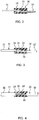
- FIG. 1 is a partial perspective view of a connection structure according to an embodiment.
- FIG. 2 is a schematic partial cross-sectional view of the connection structure according to a first embodiment.
- a connection structure 30 is constructed of a plurality of conductive members 31 and 32, a connection part 33 in which the conductive members 31 and 32 are electrically connected together and a molded body 34 in which the connection part 33 is embedded.
- the entire connection part 33 is embedded in the molded body 34.
- FIG. 1 and FIG. 2 the conductive members 31 and 32 extend in opposite directions from mutually facing surfaces of the molded body 34 respectively.
- the positional relationship between the conductive members 31 and 32 with respect to the molded body 34 is presented as an example, which is however not particularly limited.
- FIG. 2 to FIG. 7 illustrate a configuration in which a plurality of conductive members extend in mutually opposite directions from the mutually facing surfaces of the molded body 34.
- the conductive members 31 and 32 shown in FIG. 1 and FIG. 2 are bare conductive members (conductors) and distal end portions of the respective conductive members 31 and 32 are electrically connected together.
- a method for forming the connection part 33 is not particularly limited, but, examples thereof include welding, soldering, swaging using a metallic ring.
- FIG. 2 is an example where the conductive members 31 and 32 are welded together. Note that cross-sectional shapes of the conductive members 31 and 32 may be round or rectangular, but these shapes do not limit their cross-sectional shapes.
- the materials of the conductive members 31 and 32 are not particularly limited, but they are formed of conductors such as aluminum, silver or copper, and copper can be mainly used.
- the conductive members 31 and 32 may be made of conductors of the same material or conductors of different materials. Conductors of different kinds of metals may be preferably used in the present embodiment in particular.
- the molded body 34 is a rectangular body, which however does not limit the shape and an arbitrary shape can be adopted such as a columnar or disk shape. Furthermore, as shown in FIG. 1 , a fixing hole 39 may be provided in the molded body 34. The number of fixing holes 39 is not limited.
- the molded body 34 is integrally molded and includes no break or the like.
- the molded body 34 is preferably formed of thermoplastic resin.
- the material used as the molded body 34 preferably has a high electrical insulating property and excellent heat resistance, and to be more specific, polycarbonate (PC), polyacetal (POM), polybutylene terephthalate (PBT), polyphenylene sulfide (PPS), liquid crystal polymer (LCP), polypropylene (PP), polyethylene (PE) or the like are suitably used.
- the size of the molded body 34 is not particularly limited, but a width T1 and a length L1 are on the order of 5 mm to 20 mm and a height H1 is on the order of 5 mm to 10 mm.
- FIG. 3 is a schematic partial cross-sectional view of a connection structure according to a second embodiment.
- the conductive members 31 and 32 are conductive members with insulating coating obtained by applying an insulating coating 37 to surfaces of conductors 35 and 36, and in FIG. 3 , the insulating coating 37 of the part of the connection part 33 is peeled to expose the conductors 35 and 36, and the exposed conductors 35 and 36 are connected together through welding or the like.
- the connection part 33 is embedded in the molded body 34 to secure electrical insulation of the connection part 33 from the outside.
- the insulating coating 37 is not particularly limited, and examples thereof include enamel and Holmet coating. That is, the conductive members 31 and 32 in FIG. 3 are enamel wires, Holmet wires or the like. Note that FIG. 3 shows a front view of the part of the insulating coating 37 in a state in which the conductors 35 and 36 are coated instead of showing a cross-sectional view thereof. The same applies to FIG. 4 , FIG. 6 , FIG. 7 , FIG. 9 to FIG. 11 , and FIG. 13 to FIG. 15 .
- FIG. 4 is a schematic partial cross-sectional view of a connection structure according to a third embodiment.
- parts assigned the same reference numerals as those in FIG. 2 denote the same members as those in FIG. 2 .
- the conductors 35 and 36 except the connection part 33 are coated with an insulating member 38.
- the material of the insulating member 38 is not limited, for example, vinyl may be used as the material. That is, the conductive members 31 and 32 in FIG. 4 are vinyl-coated electric wires or the like.
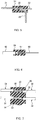
- FIG. 5 is a schematic partial cross-sectional view of a connection structure according to a fourth embodiment.
- parts assigned the same reference numerals as those in FIG. 2 denote the same members as those in FIG. 2 .
- three conductive members 31, 32 and 39 are provided.
- the conductive members 31, 32 and 39 are, for example, bare conductive members (conductors) and a connection part 33 is included where the respective conductive members 31, 32 and 39 are connected together by welding or the like.
- the connection part 33 is embedded in the molded body 34 to secure electrical insulation of the connection part 33 from the outside.
- the number of conductive members used as the connection structure can be set to three or more.
- FIG. 6 is a schematic partial cross-sectional view of a connection structure according to a fifth embodiment.
- parts assigned the same reference numerals as those in FIG. 2 denote the same members as those in FIG. 2 .
- conductive members 45 and 46 of different types are electrically connected together.
- the conductive member 45 is a vinyl-coated electric wire and the conductive member 46 is an enamel wire.
- Conductors are exposed at distal ends of the conductive members 45 and 46, and the conductors of the respective conductive members 45 and 46 are electrically connected together, for example, by soldering.
- a connectionpart 47 is thereby formed.
- the connection part 47 is embedded in the molded body 34 to secure electrical insulation of the connection part 47 from the outside.
- FIG. 7 is a schematic partial cross-sectional view of a connection structure according to a sixth embodiment.
- parts assigned the same reference numerals as those in FIG. 3 denote the same members as those in FIG. 3 .
- a plurality of sets of the electrically connected conductive members 31 and 32 shown in FIG. 3 are provided and the connection part 33 of each set of the conductive members 31 and 32 is embedded in the molded body 34 to secure electrical insulation of each connection part 33 from the outside.
- a configuration is provided in which a plurality of connection parts 33 are embedded in one molded body 34.
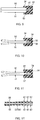
- FIG. 8 is a partial perspective view of a connection structure according to an embodiment different from that in FIG. 1 .
- FIG. 9 is a schematic partial cross-sectional view of a connection structure according to a seventh embodiment.
- FIG. 10 is a schematic partial cross-sectional view of a connection structure according to an eighth embodiment.
- FIG. 9 and FIG. 10 illustrate cross sections of the connection structure shown in FIG. 8 cut in a plane direction.
- parts assigned the same reference numerals as those in FIG. 2 denote the same members as those in FIG. 2 .
- connection part 54 As shown in FIG. 8 , FIG. 9 and FIG. 10 , conductive members 50 and 51 constitute parallel electric wires with an insulating coating, insulating coatings are removed at distal ends of the respective conductive members 50 and 51, exposedconductors 52, 53 (55, 56) are electrically connected together by welding or the like to form a connection part 54.
- the connection part 54 is embedded in the molded body 34 to secure electrical insulation of the connection part 54 from the outside.
- FIG. 11 is a schematic partial cross-sectional view of a connection structure according to a ninth embodiment.
- parts assigned the same reference numerals as those in FIG. 10 denote the same members as those in FIG. 10 .
- FIG. 11 recesses 57 are provided in surfaces of the conductive members 50 and 51 embedded in the molded body 34.
- FIG. 12 is a partially enlarged schematic cross-sectional view of the recesses in FIG. 11 .
- the recess (bottomed concave portion) 57 penetrates an insulating coating 58 and reaches a conductor 55 (56) providing a dent in the conductor 55 (56).
- the recess 57 is formed only in the part of the insulating coating 58, but the recess 57 is preferably formed in the conductor 55 (56). It is thereby possible to more effectively prevent the molded body from coming off.
- dents are likely to be produced in the connection part 54 because of welding or the like, the recess 57 is preferably provided in any place other than the connection part 54.
- FIG. 13 is a schematic partial cross-sectional view of a connection structure according to a tenth embodiment.
- a conductive member 45 is, for example, a vinyl-coated electric wire and a conductive member 46 is an enamel wire. Conductors are exposed at distal ends of the conductive members 45 and 46, and the conductors of the respective conductive members 45 and 46 are electrically connected together by soldering. In this way, a connection part 47 is formed.
- the respective conductive members 45 and 46 are caused to extend to the outside from the same surface side of the molded body 34.
- a conductive member 60 made up of an enamel wire or the like is further electrically connected to the connection part 47 in FIG. 13 .
- FIG. 15 a plurality of sets of the electrically connected conductive members 45 and 46 shown in FIG. 13 are provided, the respective connection parts 47 are embedded in the molded body 34 to secure electrical insulation of each connection part 47 from the outside.
- the molded body 34 shown in FIG. 1 to FIG. 15 can be molded using an injection apparatus that incorporates a melter shown below.
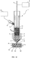
- FIG. 16 is a schematic cross-sectional view of the injection apparatus according to the present embodiment.
- FIG. 17 is a schematic cross-sectional view of the injection apparatus illustrating a state in which resin pellets are supplied to the injection apparatus shown in FIG. 16 .
- FIG. 17 is a schematic cross-sectional view for describing a molding step of a connection structure using the injection apparatus according to the present embodiment.
- An injection apparatus 1 is constructed of a cylinder 2, a melter 3 disposed in the cylinder 2, a nozzle part 4 located at a distal end of the injection apparatus 1, heating means for heating the melter 3, and pressurizing means for pressurizing molten resin and ejecting the resin to the outside from the nozzle part 4.
- the melter 3 shown in FIG. 16 is fixed to the inside of the cylinder 2.
- the melter 3 is disposed on a distal end 2a side of the cylinder 2 (lower side in FIG. 1 ).
- a plunger 5 is provided in the cylinder 2 as the pressurizing means.
- the plunger 5 is disposed closer to a rear end 2b side of the cylinder 2 than the melter 3 (upper side in FIG. 1 ).
- a predetermined distance is provided between the melter 3 and the plunger 5.
- the plunger 5 is supported by drive means so as to be movable in a vertical direction (reciprocating movement).
- the vertically movable plunger 5 is located at a most retracted position in the rear end direction of the cylinder 2 in FIG. 16 and FIG. 17 , and FIG. 18 illustrates a state in which the plunger 5 is moved from the state in FIG. 17 toward the distal end direction of the cylinder 2 (downward direction in FIG. 16 ).
- the cylinder 2 is formed into an elongated cylindrical shape having substantially constant inner diameter and outer diameter from the distal end 2a to the rear end 2b, but the shape thereof is not particularly limited. That is, the shape of the cylinder 2 is not particularly limited as long as the cylinder 2 has a mode in which the melter 3 can be fixed in the cylinder 2 and the plunger 5 as the pressurizing means can be moved in the vertical direction.
- the cylinder 2 may have a square shape whose interior is hollow.
- the material of the cylinder 2 is not particularly limited, but iron or stainless steel with a large content of iron or the like is preferably used out of the necessity for rapid heating.
- the cylinder 2 is provided with a pellet supply port 2c.
- the pellet supply port 2c is formed into a hole shape communicating with a space in the cylinder so that the pellet supply port 2c is located between the melter 3 fixed on the distal end 2a side of the cylinder 2 and the plunger 5 in a state in which it is retracted toward the rear end 2b direction of the cylinder 2 (upward direction in the figure).
- a cylindrical supply pipe 12 is connected to the pellet supply port 2c.
- a top end of the supply pipe 12 communicates with a storage part 18 that stores many resin pellets (injection material) and resin pellets are supplied from the storage part 18 to the pellet supply port 2c via the supply pipe 12.
- the storage part 18 is, for example, a hopper.
- the storage part 18 is provided with a screw conveyance or pneumatic apparatus, and can also forcibly charge resin pellets into the supply pipe 12. Note that without providing any storage part, resin pellets may also be supplied through a pipe from a remote place through screw conveyance or pneumatic transportation.
- the plunger 5 is constructed of a pressing part 5a and a cylindrical outer circumferential side face part 5b provided around the pressing part 5a and formed toward the rear end 2b direction of the cylinder 2. As shown in FIG. 16 , the size of the pressing part 5a coincides with the inner diameter of the cylinder 2 and a spatial region of the cylinder 2 from the pressing part 5a to the rear end 2b of the cylinder 2 is closed with the plunger 5. Note that rigid heat-resistant synthetic resin is fixed to the front face of the pressing part 5a (undersurface side in the figure) as needed. This makes it possible to thermally insulate the melter 3 from the plunger 5 to prevent the plunger 5 from depriving the melter 3 of heat and prevent the plunger 5 from being heated to transmit heat to a drive section 8.
- the plunger 5 is connected to the drive section 8 and the plunger 5 is supported so as to be able to move in the vertical direction (reciprocating movement) inside the cylinder 2 by a drive force of the drive section 8.
- a drive transmission shaft (rod) 9 is disposed between the drive section 8 and the plunger 5, and the drive section 8 and the drive transmission shaft 9 together constitute "drive means.”
- the drive section 8 is a motor drive section and the drive transmission shaft 9 is a rack shaft, a pinion gear (not shown) is disposed between the motor drive section and the rack shaft, and the drive means is constructed of the motor drive section, the rack shaft and the pinion gear.
- the cross-sectional shape of the drive transmission shaft (rod) 9 is, for example, circular, but the shape is not limited.
- heating means 6 for heating the melter 3 is provided around the cylinder 2.
- the heating means 6 is a component to heat the melter 3 from the outer circumferential surface of the cylinder 2 and is preferably formed to be cylindrical so that thermal conductivity to the melter 3 improves.
- the heating means 6 is provided at a position facing the melter 3 (so as to surround the melter 3).
- the heating means 6 is made up of an IH heater or the like configured like winding.
- the heating means 6 is preferably an electromagnetic induction apparatus, that is, IH (induction heating) coil, and is an IH coil wound around a resin or ceramic heat insulating material coil bobbin.
- IH induction heating
- a band heater may also be used as another type of the heating means 6.
- the heating means 6 is not limited to the above-described one, but any means may be used if it is another heating apparatus available to the present invention.
- the cylinder 2 is preferably provided with a thermocouple so as to be able to adjust the temperature of the cylinder 2 to a set value.
- the melter 3 is provided with a plurality of through holes (melting holes) 10 in the height direction.
- the shape of the outer circumferential surface of the melter 3 matches the shape of the inner wall surface of the cylinder 2 so that the entire outer circumferential surface of the melter 3 comes into contact with the inner wall surface of the cylinder 2. Therefore, if the inner wall surface (hollow part) of the cylinder 2 is shaped like a column, the outer circumferential surface of the melter 3 is also shaped like a column having the same diameter.
- an opening on the top surface side of the melter 3 of each through hole 10 is an inflow port and an opening on the undersurface side of the melter 3 of each through hole 10 is an outflow port.
- the material of the melter 3 metal which has a large heat capacity and excellent heat conduction or excellent heat resistance is suitable.
- copper, beryllium copper, brass, stainless steel, gold, chromium steel, nickel chromium steel, molybdenum steel, tungsten steel or the like is used, but the material is not particularly limited. Forming the melter 3 to a size, which will be described later, can effectively suppress unmelted residues of the resin pellets P (injection material).
- a head part 11 provided with the nozzle part 4 is provided at the distal end 2a of the cylinder 2.
- the head part 11 is constructed of the nozzle part 4, a funnel part 13 and a connection part 14.
- the head part 11 is connected to the cylinder 2 via the connection part 14.
- a material with good heat conduction is suitable for the head part 11 and, to be more specific, beryllium copper or copper is preferable.
- the material of the resin pellets P is not particularly limited, the material used as the molded body 34 preferably has a high electric insulating property and excellent heat resistance. Therefore,polycarbonate (PC), polyacetal (POM), polyethylenebutylene terephthalate (PBT), polyphenylene sulfide (PPS), liquid crystal polymer (LCP) or the like are suitable as the resin pellets P. Note that each resin pellet P has a diameter or a long side in size of on the order of 1 to 1.5 mm.
- the resin pellets P When the resin pellets P reach an upper part of the melter 3, the resin pellets P enter each through hole (melting hole) of the melter 3 from the inflow port (top surface in the figure). The resin pellets P which have entered each through hole 10 are pressed by resin pellets P that enter later toward the outflow port side of each through hole 10 (undersurface side in the figure). In this case, the melter 3 is kept at a temperature at which the resin pellets P are melted via the heating means 6.
- the resin pellets P that have flown into each through hole 10 are partially softened by heat from the melter 3.
- the drive means is driven to drive the plunger 5 as the pressurizing means toward the direction of the nozzle part 4 (downward direction in the figure). This causes all the many resin pellets P located between the inflow port side of the melter 3 (top surface in the figure) and the undersurface of the pressing part 5a of the plunger 5 to be pressed against each other. As shown in FIG. 18 , the pellet supply port 2c is closed with the plunger 5 due to the downward movement of the plunger 5.
- the resin pellets P that have flown into each through hole 10 of the melter 3 are also pressurized.
- the resin pellets P are pressurized and placed in a hermetically sealed condition in each through hole 10, further melted by heat from the melter 3 and molten resin q flows from the outflow port (undersurface side) of the melter 3 into the head part 11.
- the molten resin q is pressurized while being kept in the highly hermetically sealed condition and ejected to the outside from the nozzle part 4.
- the nozzle part 4 is located at a supply port 21a of an upper die 21 making up the molding die and injects the molten resin q into the upper die 21 and the lower die 22.
- the charged molten resin q is then cooled to become solid.
- An injection time of the molten resin q by the injection apparatus 1 is several hundreds of milliseconds to several seconds (e.g., on the order of onesecond). As shown in FIG.
- a conductive connection body 62 which is composed of a plurality of conductive members electrically connected together in advance is arranged in the molding die, and it is possible to embed the conductive connection body 62 in a molded body 64 through injection of the molten resin q and thereby secure electrical insulation of the connection part 63 of a conductive connection body 62 from the outside.
- the melter 3 is provided with a plurality of through holes 10.
- the melter 3 is provided with a function for passing the resin pellets P through each through hole 10 and melting the resin pellets P.
- this is likely to cause clogging in the through hole 10.
- the melter 3 is required to have a mode capable of effectively preventing unmelted residues of the resin pellets P when generating molten resin.
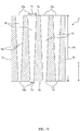
- FIG. 19 is a longitudinal cross-sectional view of the melter as the first embodiment .
- the melter 3 includes a top surface 3a, an undersurface 3b and an outer circumferential surface 3c located between the top surface 3a and the undersurface 3b.
- the top surface 3a and the undersurface 3b are surfaces facing each other and parallel to each other.
- a plurality of through holes 10 provided from the top surface 3a to the undersurface 3b (toward the height direction (Z)) are formed in the melter 3.
- An opening of each through hole 10 in the top surface 3a is an inflow port 10a and an opening in the undersurface 3b is an outflow port 10b.
- the number of through holes 10 can be set arbitrarily, the number of through holes 10 is preferably plural. Furthermore, the number of through holes 10 may be preferably set so that the ratio of the total area of the inflow ports 10a of the respective through holes 10 to the area of the top surface 3a (inflow port surface) of the melter 3 becomes, for example, 50% or higher.
- the plurality of through holes 10 may be arranged regularly or randomly, it is possible to increase melting efficiency by uniformly distributing the respective through holes 10 over the entire top surface (inflow port surface) 3a and undersurface (outflow port surface) 3b.
- an inner wall surface 10c of the through hole 10 is formed of an inclined surface so that the opening gradually becomes narrower from the inflow port 10a to the outflow port 10b in each through hole (melting hole) 10.
- the respective through holes 10 are preferably formed in a direction parallel to the height direction (Z) from the inflow port 10a to the outflow port 10b.
- Each through hole 10 is preferably frustum-shaped, and to be more specific, truncated cone or truncated pyramid may be presented. In FIG. 19 , each through hole 10 has a truncated cone shape.
- the inflow port 10a of each through hole 10 has an opening width of T1 and the outflow port 10b of each through hole 10 has an opening width of T2.
- the opening width T1 is greater than the opening width T2.
- the opening width T1 and the opening width T2 can be calculated as opening diameters.
- the opening width T1 and the opening width T2 represent the widths of the longest straight lines of the sides or diagonals.
- the opening width T1 is adjusted to within a range of 4.1 mm to 10 mm and the opening width T2 is adjusted to within a range of 1.0 mm to 4.5 mm.
- notations "lower limit value to upper limit value” is assumed to include a lower limit value and an upper limit value.
- the resin pellets P are caused to flow from the inflow port 10a of each through hole 10 of the melter 3 into the melter 3 shown in FIG. 19 , heated, pressurized and melted, and molten resin is caused to flow out from the outflow port 10b of each through hole 10.
- the inflow port 10a of each through hole 10 is opened greater than the outflow port 10b. For this reason, the resin pellets P can be more easily guided into the inflow port 10a of the through hole 10. Since the opening width T1 of the inflow port 10a is adjusted to within the range of 4.1 mm to 10 mm, it is possible to substantially cover sizes of various commercially available resin pellets and appropriately guide the resin pellets P into the inflow port 10a.
- the resin pellets P are melted in the melter 3 and discharged out from the outflow port 10b, but since the inner wall surface 10c of the through hole 10 is an inclined surface, it is possible to smoothly guide the molten resin toward the direction of the outflow port 10b and by making the opening width T2 of the outflow port 10b narrower than the opening width T1 of the inflow port 10a, it is possible to increase the heat quantity and extrusion pressure on the outflow port 10b side and cause the molten resin to flow out from the outflow port 10b appropriately. Then, in the embodiment shown in FIG.
- the opening width T1 of the inflow port 10a is set to 4.1 mm to 10 mm and the opening width T2 of the outflow port 10b is set to 1.0 mm to 4.5 mm.
- a length H2 from the inflow port 10a to the outflow port 10b of the through hole 10 is preferably 30 mm to 200 mm.
- the length H2 is determined by the size in a direction parallel to the height direction (Z) from the inflow port 10a to the outflow port 10b.
- Z height direction
- the melting path from the inflow port to the outflow port becomes shorter, increasing the possibility that unmelted residues of resin pellets P may be generated.
- the length of the through hole 10 is too large, the inner wall surface of the through hole 10 becomes closer to a vertical surface than the inclined surface, causing a relative rise in the heat quantity and extrusion pressure on the outflow port 10b side with respect to the inflow port side to be more likely to decrease.
- the length H2 is preferably 70 mm to 150 mm.
- the present embodiment appropriately adjusts the respective opening widths of the inflow port 10a and the outflow port 10b of the through hole 10 as well as the length of the through hole 10, and can thereby more effectively eliminate unmelted residues of resin pellets P and improve melting efficiency.
- the opening width T1 of the inflow port 10a is preferably 4.1 mm to 6 mm. Furthermore, the opening width T2 of the outflow port 10b is preferably 1.0 mm to 2.9 mm. The lower limit value of the opening width T2 of the outflow port 10b is more preferably 1.6 mm.
- FIG. 20 is a longitudinal cross-sectional view of a melter according to a second embodiment.
- the inner wall surface 10c of the through hole 10 is formed of an inclined surface in such a way that the opening gradually becomes narrower from the inflow port 10a to the outflow port 10b.
- each through hole 10 is formed of an inclined surface (first inclined surface) 70 having an opening angle of ⁇ 1 and a gently inclined surface (second inclined surface) 71 having an opening angle of ⁇ 2 on the inflow port 10a side.
- first inclined surface first inclined surface
- second inclined surface second inclined surface
- ⁇ 1 ⁇ 2 ⁇ 120° A relationship of ⁇ 1 ⁇ 2 ⁇ 120° is satisfied.
- the opening angle ⁇ 1 also has a similar opening angle in FIG. 20 , and the opening angle ⁇ 1 is defined by a relationship between the inflow port 10a and the outflow port 10b.
- the "opening angle” refers to an angle formed between mutually facing inclined surfaces in the cross section shown in FIG. 20 and when an angle of inclination of each inclined surface is defined as an angle from the height direction (Z), the opening angle becomes substantially twice the angle of inclination.
- the edges 10d have a blade shape or blade-like shape, and when the resin pellets P are located on the edges 10d, the resin pellets P are crushed, separated apart into fine pieces, which further facilitates entries of the resin pellets P into the through hole 10 and suppresses clogging in the through hole 10.
- the inclined surface 70 having a steep inclination is formed from the outflow port 10b to a position close to the inflow port 10a and the gently inclined surface 71 having a gentle inclination is formed only in the vicinity of the inflow port 10a.
- the inclined surface may be formed so as to have three or more stages. Note that the inclined surface is preferably formed in a two-stage inclination structure in which most of the through hole is formed of the steep inclined surface 70 and the gently inclined surface 71 is formed only in the vicinity of the inflow port 10a.
- the inner wall surface of the through hole 10 is formed of an inclined surface first so that the opening becomes narrower from the inflow port 10a to the outflow port 10b of the through hole 10. Since the opening of the inflow port 10a is greater than that of the outflow port 10b in this way, it is possible to guide the resin pellets P into the inflow port 10a of the through hole 10 more easily.
- the resin pellets P are melted in the melter 3 and flow out from the outflow port 10b, and since the inner wall surface of the through hole 10 is an inclined surface in this case, the resin pellets P can be smoothly guided toward the outflow port direction, and moreover by making the opening of the outflow port 10b narrower than the opening of the inflow port 10a, it is possible to increase the heat quantity and extrusion pressure on the outflow port side and cause molten resin to flow out from the outflow port 10b appropriately.
- the gently inclined surface 71 is formed on the inflow port 10a side. This further makes it easier to guide the resin pellets P into the inflow port 10a of the through hole 10.
- the present embodiment particularly satisfies a relationship of ⁇ 1 ⁇ 2 ⁇ 120°.
- ⁇ 2 is preferably 30° to 120°.
- ⁇ 2 is more preferably 30° to 90°.
- ⁇ 2 is further preferably 30° to 60°.
- the opening angle ⁇ 1 is determined by the sizes of the inflow port 10a and the outflow port 10b and is an angle at least smaller than the opening angle ⁇ 1.
- ⁇ 1 is on the order of 0° to 20° or on the order of 0° to 10°.
- the opening width T1 of the inflow port 10a is preferably 4.1 mm to 10 mm and the opening width T2 of the outflow port 10b is preferably 1 . 0 mm to 4.5 mm.
- the opening width T1 of the inflow port 10a is preferably 4.1 mm to 6 mm and the opening width T2 of the outflow port 10b is more preferably 1.0 mm to 2.9 mm.
- the lower limit value of the opening width T2 is further preferably 1.6 mm.
- the length H1 from the inflow port 10a to the outflow port 10b of the through hole 10 is preferably 30 mm to 200 mm.
- the length H1 is more preferably 70 mm to 150 mm.
- the melter 3 according to the present embodiment is used not only by being fixed in the injection apparatus 1 as shown in FIG. 16 but also by being configured to move in the vertical direction (reciprocating movement) through a cylinder as will be described below.
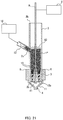
- FIG. 21 is a schematic cross-sectional view of an injection apparatus according to an embodiment different from that in FIG. 16 , illustrating a state in which resin pellets are supplied.
- FIG. 22 is a schematic cross-sectional view of the injection apparatus illustrating a state in which the melter which can move in the vertical direction (reciprocating movement) is caused to move upward from the state in FIG. 21 .
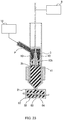
- FIG. 23 is a schematic cross-sectional view of the injection apparatus illustrating a state in which the melter is caused to move downward from the state in FIG. 22 and molten resin is ejected to the outside from the nozzle part.
- FIG. 21 to FIG. 23 parts identical to those in FIG. 16 to FIG. 18 are assigned identical reference numerals.
- the melter 3 and the drive section 8 are connected together via the drive transmission shaft 9.
- a closing member 40 is provided closer to the rear end side of the cylinder 2 than the melter 3.
- the planar area of the closing member 40 coincides with the planar area of the space surrounded by the inner wall surface in the cylinder 2.
- the closing member 40 is fixed in the cylinder 2.
- the drive transmission shaft 9 penetrates the closing member 40 and is connected to the melter 3. As shown in FIG. 21 , the drive transmission shaft 9 penetrates the melter 3 at the center and the melter 3 and the drive transmission shaft 9 are fixed and connected together.
- an opening/closing member 41 is provided on the undersurface (outflow port surface) 3b side of the melter 3.
- the opening/closing member 41 is supported so as to close or release the outflow port of each through hole 10 of the melter 3 based on vertical movement of the melter 3.
- the opening/closing member 41 is always urged toward the undersurface (outflow port surface) of the melter 3 using, for example, an elastic member (not shown). Operations of the drive section 8 and the drive transmission shaft 9 can release the opening/closing member 41 from the undersurface 3b of the melter 3.
- the opening/closing member 41 is formed with an area smaller than that of the melter 3.
- a through hole may also be formed in the opening/closing member 41. In this case, the position and size of the through hole formed in the opening/closing member 41 are restricted so as not to overlap those of the outflowport 10b of each through hole 10 of the melter 3.
- the melter 3 is located on the distal end side of the cylinder 2 and in an initial state of FIG. 21 , many solid resin pellets (injection material) P are supplied into the cylinder 2 from the storage part 18 via the supply pipe 12.
- the resin pellets P are introduced into each through hole (melting hole) 10 of the melter 3 from the inflow port (top surface in the figure).
- the resin pellets P which have entered each through hole 10 are pressed toward the outflow port side of each through hole 10 (undersurface side in the figure) by resin pellets P that enter later.
- the melter 3 is kept at a temperature at which the resin pellets P are melted via the heating means 6.
- the resin pellets P that have flown into each through hole 10 are partially softened by heat from the melter 3.
- drive means is driven to drive the melter 3 toward the direction of the closing member 40 (upward direction in the figure) (melting step). This causes all the many resin pellets P located between the inflow port side of the melter 3 (top surface in the figure) and the undersurface of the closing member 40 to be pressed against each other.
- the melter 3 can keep the heat source sufficiently in terms of the heat capacity of the melter 3.
- a heat-insulating structure is preferably provided between the melter 3 and the drive transmission shaft 9 so as to prevent heat of the melter 3 from transmitting to the drive transmission shaft 9.
- the resin pellets P charged into each through hole (melting hole) 10 of the melter 3 are heated and pressurized while being kept in an hermetically sealed condition, and thus caused to start melting.
- the opening/closing member 41 located on the undersurface (outflow port) 3b side of the melter 3 is released from the melter 3. In this way, molten resin q that has flown downward from the melter 3 remains between the melter 3 and the nozzle part 4.
- the drive means is operated to cause the melter 3 to move toward the direction of the nozzle part 4 (downward in the figure) (injection step).
- the opening/closing member 41 is in contact with the undersurface 3b of the melter 3, closing the outflow port 10b of each through hole 10 of the melter 3.
- molten resin q remaining between the melter 3 and the nozzle part 4 is pressurized while being kept hermetically sealed and ejected from the nozzle part 4.
- the molten resin q is injected between the upper die 21 and the lower die 22 making up the molding die. As shown in FIG.
- a conductive connection body 62 composed of a plurality of conductive members electrically connected together in advance are arranged in the molding die, and it is possible to embed the conductive connection body 62 in a molded body 64 through injection of the molten resin q and thereby secure electrical insulation of a connection part 63 of the conductive connection body 62 from the outside.
- the injection apparatus shown in FIG. 21 to FIG. 23 can also more effectively improve melting efficiency compared to the prior arts.
- connection structure includes a plurality of conductive members, a connection part that electrically connects the conductive members and an electrically insulating molded body in which the connection part is embedded.
- the method for manufacturing the connection structure according to the present embodiment includes molding an electrically insulating molded body around the connection part which electrically connects a plurality of conductive members and embedding the connection part in the molded body.
- connection part that electrically connects conductive members is protected with an insulating cap.
- the present embodiment protects the connection part of the conductive members by embedding the connection part in the molded body.
- a gap is likely to be generated anyway between the insulating cap and the connection part and there is concern about a problem with corrosion.
- the impact propagates up to the connection part inside the insulating cap, causing damage to the connection part.
- the volume of the insulating cap is too large to house the insulating cap.
- connection part of the conductive members in the molded body as in the case of the present embodiment, it is possible to physically reinforce the connection part of the conductive members and keep it hermetically sealed, thereby prevent corrosion and increase reliability compared to the prior arts. Furthermore, since the connection part need not maintain mechanical strength by itself, it is possible to promote minimization (miniaturization) appropriate for the current capacity, and even if there are a plurality of connection parts, it is possible to miniaturize the connection structure. For this reason, it is possible to make the high current connection part highly reliable and reduce the size and weight thereof.
- the recess 57 is preferably formed in the portion of the conductive member which is embedded in the molded body as shown in FIG. 11 .
- the recesses 57 are more effectively formed in parts other than the connection part. It is thereby possible to fit molten resin into the recesses 57 when molding the molded body 34, increase the contact area between the conductor and resin, and more effectively prevent the molded body from coming off.
- the present embodiment adopts a configuration in which the connection part is embedded in the molded body, it is possible to effectively keep the connection part in a hermetically sealed condition. Therefore, even when conductors of different kinds of metals are used for a plurality of conductive members, it is possible to appropriately prevent the occurrence of galvanic corrosion caused by potential differences among different kinds of metals.
- the "different kinds of metals” include metals made of different elements or metals with different mixing ratios. For example, metals with different iron-to-copper ratios are also considered as different kinds of metals.
- the melter includes through holes, one opening of each through hole is an inflow port of resin pellets (injection material) and the other opening is an outflow port of the resin pellets (injection material) and an inner wall surface of the through hole is formed of an inclined surface so that the opening becomes narrower from the inflow port to the outflow port of the through hole.
- a gently inclined surface which is continuous to the inclined surface and more gently inclined than the inclined surface is preferably formed on the inflow port side of the melter.
- the molding die is, for example, a metal plate processed so as to include a concave part.
- the conductive member is generally already incorporated as part of equipment, an apparatus or a machine. That is, in a state in which the conductive member singly exists, a molding step of the molded body is not executed.
- injection apparatuses are quite large and molding dies used to injection-mold molded bodies are also quite large. For this reason, conventionally, there have been no ideas of embedding the connection part of conductive members incorporated as part of equipment, an apparatus or a machine (it has been difficult to mold the molded body).
- an insulating cap or the like is conventionally used.
- the present embodiment uses an injection apparatus that incorporates the melter, and can thereby achieve downsizing of the injection apparatus and downsizing of the molding die, simply set the molding die in the connection part of the conductive member which is already incorporated as part of equipment, an apparatus or a machine, and mold a small molded body only in part of the connection part using the injection apparatus of the present embodiment.
- connection part which electrically connects a plurality of conductive members in a molded body
- a protection condition of the connection part is extremely important in securing reliability in equipment, an apparatus, a machine or the like for which many connection members need to be connected in series.
- the transport equipment include automobile, aircraft, railroad, and vessel.
- automobiles include electric vehicles.
- the power equipment include battery such as solar battery.
- Examples of the power generation equipment include thermal power generation elements.
- Examples of the space equipment include rocket and artificial satellite.
- Use of the connection structure of the present embodiment in this case makes it possible to appropriately meet high current, high strength and high heat resistance requirements and achieve high reliability. Furthermore, it is possible to reduce the size and weight of the high-current connection part.
- the present invention can physically reinforce the connection part of the conductive member and keep the connection part in a hermetically sealed condition to thereby prevent corrosion, and can provide a connection structure capable of increasing reliability compared to the prior arts.
- Use of the connection structure according to the present embodiment makes it possible to manufacture an electric vehicle, solar battery or thermal power generation element or the like with excellent reliability.
Landscapes
- Engineering & Computer Science (AREA)
- Manufacturing & Machinery (AREA)
- Mechanical Engineering (AREA)
- Power Engineering (AREA)
- Injection Moulding Of Plastics Or The Like (AREA)
- Manufacturing Of Electrical Connectors (AREA)
Applications Claiming Priority (2)
| Application Number | Priority Date | Filing Date | Title |
|---|---|---|---|
| JP2014200200 | 2014-09-30 | ||
| PCT/JP2015/077409 WO2016052453A1 (ja) | 2014-09-30 | 2015-09-29 | 接続構造体及びその製造方法、並びに、輸送機器、電力機器、発電機器、医療機器、宇宙機器 |
Publications (2)
| Publication Number | Publication Date |
|---|---|
| EP3203585A1 true EP3203585A1 (de) | 2017-08-09 |
| EP3203585A4 EP3203585A4 (de) | 2018-04-25 |
Family
ID=55630481
Family Applications (1)
| Application Number | Title | Priority Date | Filing Date |
|---|---|---|---|
| EP15846196.2A Withdrawn EP3203585A4 (de) | 2014-09-30 | 2015-09-29 | Verbindungsstruktur und herstellungsverfahren dafür sowie transportausrüstung, stromausrüstung, stromerzeugungsausrüstung, medizinische ausrüstung und weltraumausrüstung |
Country Status (6)
| Country | Link |
|---|---|
| US (1) | US20170287600A1 (de) |
| EP (1) | EP3203585A4 (de) |
| JP (1) | JPWO2016052453A1 (de) |
| KR (1) | KR20170083536A (de) |
| CN (1) | CN107148704A (de) |
| WO (1) | WO2016052453A1 (de) |
Families Citing this family (6)
| Publication number | Priority date | Publication date | Assignee | Title |
|---|---|---|---|---|
| WO2017199700A1 (ja) * | 2016-05-19 | 2017-11-23 | 東洋紡株式会社 | ワイヤハーネス |
| JP6822381B2 (ja) * | 2017-11-06 | 2021-01-27 | 株式会社デンソー | 通電部材モジュール、及びその製造方法 |
| JP2019084740A (ja) * | 2017-11-06 | 2019-06-06 | 株式会社デンソー | 通電部材モジュール、及びその製造方法 |
| JP7147839B2 (ja) * | 2018-03-28 | 2022-10-05 | 株式会社オートネットワーク技術研究所 | ワイヤーハーネスおよびワイヤーハーネスの製造方法 |
| CN109494546A (zh) * | 2018-10-26 | 2019-03-19 | 景宁众驰自动化科技有限公司 | 电源线插头加工生产线及其制作工艺 |
| CN111716628A (zh) * | 2020-06-29 | 2020-09-29 | 安徽可尔海思塑业有限公司 | 一种抗变形的pvc塑料板及其生产工艺 |
Family Cites Families (11)
| Publication number | Priority date | Publication date | Assignee | Title |
|---|---|---|---|---|
| JP3846757B2 (ja) * | 1997-08-06 | 2006-11-15 | 古河電気工業株式会社 | ケーブル |
| DE19804607C2 (de) * | 1998-02-06 | 2000-02-10 | Bosch Gmbh Robert | Anordnung zum elektrischen Anschluß zumindest eines Sensors |
| JP2000348791A (ja) * | 1999-06-01 | 2000-12-15 | Sumitomo Wiring Syst Ltd | フラットケーブルと電線の接続構造 |
| WO2012127696A1 (ja) * | 2011-03-24 | 2012-09-27 | 三菱電機株式会社 | パワー半導体モジュール及びパワーユニット装置 |
| JP5712911B2 (ja) * | 2011-12-08 | 2015-05-07 | 株式会社オートネットワーク技術研究所 | 端子付電線及びその製造方法 |
| JP5965751B2 (ja) * | 2012-07-03 | 2016-08-10 | 矢崎総業株式会社 | コネクタ端子及びコネクタ端子の止水方法 |
| WO2014013697A1 (ja) * | 2012-07-16 | 2014-01-23 | 株式会社デンソー | 電子装置およびその製造方法 |
| JP6005448B2 (ja) * | 2012-09-04 | 2016-10-12 | 日本航空電子工業株式会社 | 防水コネクタ |
| JP6281677B2 (ja) * | 2013-03-08 | 2018-02-21 | 国立大学法人名古屋大学 | 磁気計測装置 |
| JP5527706B1 (ja) * | 2013-11-26 | 2014-06-25 | センチュリーイノヴェーション株式会社 | 溶融樹脂の製造法 |
| JP2015101088A (ja) * | 2014-02-17 | 2015-06-04 | センチュリーイノヴェーション株式会社 | 溶融樹脂の製造法 |
-
2015
- 2015-09-29 KR KR1020177010356A patent/KR20170083536A/ko not_active Withdrawn
- 2015-09-29 JP JP2016552034A patent/JPWO2016052453A1/ja active Pending
- 2015-09-29 US US15/513,657 patent/US20170287600A1/en not_active Abandoned
- 2015-09-29 WO PCT/JP2015/077409 patent/WO2016052453A1/ja not_active Ceased
- 2015-09-29 CN CN201580052885.2A patent/CN107148704A/zh active Pending
- 2015-09-29 EP EP15846196.2A patent/EP3203585A4/de not_active Withdrawn
Also Published As
| Publication number | Publication date |
|---|---|
| WO2016052453A1 (ja) | 2016-04-07 |
| JPWO2016052453A1 (ja) | 2017-07-20 |
| EP3203585A4 (de) | 2018-04-25 |
| KR20170083536A (ko) | 2017-07-18 |
| CN107148704A (zh) | 2017-09-08 |
| US20170287600A1 (en) | 2017-10-05 |
Similar Documents
| Publication | Publication Date | Title |
|---|---|---|
| EP3203585A1 (de) | Verbindungsstruktur und herstellungsverfahren dafür sowie transportausrüstung, stromausrüstung, stromerzeugungsausrüstung, medizinische ausrüstung und weltraumausrüstung | |
| US9225076B2 (en) | Connection element for an electrical conductor | |
| US7732072B2 (en) | Rechargeable battery | |
| JP6329251B2 (ja) | 電気端子を電線に圧着する方法 | |
| US20110006870A1 (en) | Coil Component And Method For Manufacturing Coil Component | |
| EP2829351B1 (de) | Zündungsvorrichtung für exothermisches schweissen, sowie vorrichtung zum exothermischen schweissen mit einer form und der entsprechenden zündungsvorrichtung | |
| US20190152110A1 (en) | Melter and injection apparatus using the same, injection molded product and manufacturing method therefor, and manufacturing method for an inter-member joining body | |
| CN100367433C (zh) | 具有电流熔断功能的温度熔断器 | |
| CN107112174A (zh) | 具有端盖配件的高流量熔线 | |
| JP2010157599A (ja) | リアクトル | |
| CN102598480A (zh) | 定子以及定子的制造方法 | |
| CN105261911B (zh) | 绞合线的接通方法 | |
| US8397639B2 (en) | Initiator with molded ESD dissipater | |
| CN113490829A (zh) | 发射体的组装体和电路切断装置 | |
| US10065342B2 (en) | Molded resin-equipped electric wire and molded resin-equipped electric wire production method | |
| EP3113287B1 (de) | Verfahren zur herstellung einer verbindungsanordnung | |
| KR102153639B1 (ko) | 전도성 입자들을 구비한 전기 와이어를 제조하기 위한 입자 어플리케이터 장치 | |
| US20170326769A1 (en) | Resin molded body | |
| EP2460207B1 (de) | Galvanische zelle mit überdrucksicherung | |
| EP3605759A1 (de) | Kern, formvorrichtung und formverfahren | |
| JP2017191925A (ja) | コイル部品及びその製造方法 | |
| US8752286B2 (en) | Method of manufacturing wire harness | |
| CA1097871A (en) | Sprue bushing with cast in heater element | |
| US6075231A (en) | Formed molding torpedo device and a method for making the same | |
| KR101377803B1 (ko) | 인서트 성형 방법 및 내부 단자 |
Legal Events
| Date | Code | Title | Description |
|---|---|---|---|
| PUAI | Public reference made under article 153(3) epc to a published international application that has entered the european phase |
Free format text: ORIGINAL CODE: 0009012 |
|
| 17P | Request for examination filed |
Effective date: 20170406 |
|
| AK | Designated contracting states |
Kind code of ref document: A1 Designated state(s): AL AT BE BG CH CY CZ DE DK EE ES FI FR GB GR HR HU IE IS IT LI LT LU LV MC MK MT NL NO PL PT RO RS SE SI SK SM TR |
|
| AX | Request for extension of the european patent |
Extension state: BA ME |
|
| DAV | Request for validation of the european patent (deleted) | ||
| DAX | Request for extension of the european patent (deleted) | ||
| A4 | Supplementary search report drawn up and despatched |
Effective date: 20180323 |
|
| RIC1 | Information provided on ipc code assigned before grant |
Ipc: B29C 45/14 20060101ALI20180319BHEP Ipc: H01R 4/70 20060101AFI20180319BHEP Ipc: H02K 5/22 20060101ALI20180319BHEP Ipc: B29L 31/34 20060101ALI20180319BHEP Ipc: B29C 45/53 20060101ALI20180319BHEP |
|
| STAA | Information on the status of an ep patent application or granted ep patent |
Free format text: STATUS: THE APPLICATION IS DEEMED TO BE WITHDRAWN |
|
| 18D | Application deemed to be withdrawn |
Effective date: 20181023 |