EP3203595B1 - Stromversorgungssystem - Google Patents
Stromversorgungssystem Download PDFInfo
- Publication number
- EP3203595B1 EP3203595B1 EP16154410.1A EP16154410A EP3203595B1 EP 3203595 B1 EP3203595 B1 EP 3203595B1 EP 16154410 A EP16154410 A EP 16154410A EP 3203595 B1 EP3203595 B1 EP 3203595B1
- Authority
- EP
- European Patent Office
- Prior art keywords
- electric power
- power system
- direct voltage
- current
- voltage rail
- Prior art date
- Legal status (The legal status is an assumption and is not a legal conclusion. Google has not performed a legal analysis and makes no representation as to the accuracy of the status listed.)
- Active
Links
Images

Classifications
-
- H—ELECTRICITY
- H02—GENERATION; CONVERSION OR DISTRIBUTION OF ELECTRIC POWER
- H02M—APPARATUS FOR CONVERSION BETWEEN AC AND AC, BETWEEN AC AND DC, OR BETWEEN DC AND DC, AND FOR USE WITH MAINS OR SIMILAR POWER SUPPLY SYSTEMS; CONVERSION OF DC OR AC INPUT POWER INTO SURGE OUTPUT POWER; CONTROL OR REGULATION THEREOF
- H02M3/00—Conversion of DC power input into DC power output
- H02M3/02—Conversion of DC power input into DC power output without intermediate conversion into AC
- H02M3/04—Conversion of DC power input into DC power output without intermediate conversion into AC by static converters
- H02M3/10—Conversion of DC power input into DC power output without intermediate conversion into AC by static converters using discharge tubes with control electrode or semiconductor devices with control electrode
- H02M3/145—Conversion of DC power input into DC power output without intermediate conversion into AC by static converters using discharge tubes with control electrode or semiconductor devices with control electrode using devices of a triode or transistor type requiring continuous application of a control signal
- H02M3/155—Conversion of DC power input into DC power output without intermediate conversion into AC by static converters using discharge tubes with control electrode or semiconductor devices with control electrode using devices of a triode or transistor type requiring continuous application of a control signal using semiconductor devices only
- H02M3/156—Conversion of DC power input into DC power output without intermediate conversion into AC by static converters using discharge tubes with control electrode or semiconductor devices with control electrode using devices of a triode or transistor type requiring continuous application of a control signal using semiconductor devices only with automatic control of output voltage or current, e.g. switching regulators
- H02M3/158—Conversion of DC power input into DC power output without intermediate conversion into AC by static converters using discharge tubes with control electrode or semiconductor devices with control electrode using devices of a triode or transistor type requiring continuous application of a control signal using semiconductor devices only with automatic control of output voltage or current, e.g. switching regulators including plural semiconductor devices as final control devices for a single load
-
- H—ELECTRICITY
- H02—GENERATION; CONVERSION OR DISTRIBUTION OF ELECTRIC POWER
- H02H—EMERGENCY PROTECTIVE CIRCUIT ARRANGEMENTS
- H02H3/00—Emergency protective circuit arrangements for automatic disconnection directly responsive to an undesired change from normal electric working condition with or without subsequent reconnection ; integrated protection
- H02H3/02—Details
- H02H3/025—Disconnection after limiting, e.g. when limiting is not sufficient or for facilitating disconnection
-
- B—PERFORMING OPERATIONS; TRANSPORTING
- B60—VEHICLES IN GENERAL
- B60L—PROPULSION OF ELECTRICALLY-PROPELLED VEHICLES; SUPPLYING ELECTRIC POWER FOR AUXILIARY EQUIPMENT OF ELECTRICALLY-PROPELLED VEHICLES; ELECTRODYNAMIC BRAKE SYSTEMS FOR VEHICLES IN GENERAL; MAGNETIC SUSPENSION OR LEVITATION FOR VEHICLES; MONITORING OPERATING VARIABLES OF ELECTRICALLY-PROPELLED VEHICLES; ELECTRIC SAFETY DEVICES FOR ELECTRICALLY-PROPELLED VEHICLES
- B60L50/00—Electric propulsion with power supplied within the vehicle
- B60L50/40—Electric propulsion with power supplied within the vehicle using propulsion power supplied by capacitors
-
- B—PERFORMING OPERATIONS; TRANSPORTING
- B60—VEHICLES IN GENERAL
- B60L—PROPULSION OF ELECTRICALLY-PROPELLED VEHICLES; SUPPLYING ELECTRIC POWER FOR AUXILIARY EQUIPMENT OF ELECTRICALLY-PROPELLED VEHICLES; ELECTRODYNAMIC BRAKE SYSTEMS FOR VEHICLES IN GENERAL; MAGNETIC SUSPENSION OR LEVITATION FOR VEHICLES; MONITORING OPERATING VARIABLES OF ELECTRICALLY-PROPELLED VEHICLES; ELECTRIC SAFETY DEVICES FOR ELECTRICALLY-PROPELLED VEHICLES
- B60L50/00—Electric propulsion with power supplied within the vehicle
- B60L50/50—Electric propulsion with power supplied within the vehicle using propulsion power supplied by batteries or fuel cells
- B60L50/51—Electric propulsion with power supplied within the vehicle using propulsion power supplied by batteries or fuel cells characterised by AC-motors
-
- H—ELECTRICITY
- H02—GENERATION; CONVERSION OR DISTRIBUTION OF ELECTRIC POWER
- H02H—EMERGENCY PROTECTIVE CIRCUIT ARRANGEMENTS
- H02H1/00—Details of emergency protective circuit arrangements
- H02H1/06—Arrangements for supplying operative power
-
- H—ELECTRICITY
- H02—GENERATION; CONVERSION OR DISTRIBUTION OF ELECTRIC POWER
- H02H—EMERGENCY PROTECTIVE CIRCUIT ARRANGEMENTS
- H02H3/00—Emergency protective circuit arrangements for automatic disconnection directly responsive to an undesired change from normal electric working condition with or without subsequent reconnection ; integrated protection
- H02H3/08—Emergency protective circuit arrangements for automatic disconnection directly responsive to an undesired change from normal electric working condition with or without subsequent reconnection ; integrated protection responsive to excess current
- H02H3/087—Emergency protective circuit arrangements for automatic disconnection directly responsive to an undesired change from normal electric working condition with or without subsequent reconnection ; integrated protection responsive to excess current for DC applications
-
- H—ELECTRICITY
- H02—GENERATION; CONVERSION OR DISTRIBUTION OF ELECTRIC POWER
- H02H—EMERGENCY PROTECTIVE CIRCUIT ARRANGEMENTS
- H02H3/00—Emergency protective circuit arrangements for automatic disconnection directly responsive to an undesired change from normal electric working condition with or without subsequent reconnection ; integrated protection
- H02H3/20—Emergency protective circuit arrangements for automatic disconnection directly responsive to an undesired change from normal electric working condition with or without subsequent reconnection ; integrated protection responsive to excess voltage
-
- H—ELECTRICITY
- H02—GENERATION; CONVERSION OR DISTRIBUTION OF ELECTRIC POWER
- H02H—EMERGENCY PROTECTIVE CIRCUIT ARRANGEMENTS
- H02H7/00—Emergency protective circuit arrangements specially adapted for specific types of electric machines or apparatus or for sectionalised protection of cable or line systems, and effecting automatic switching in the event of an undesired change from normal working conditions
- H02H7/10—Emergency protective circuit arrangements specially adapted for specific types of electric machines or apparatus or for sectionalised protection of cable or line systems, and effecting automatic switching in the event of an undesired change from normal working conditions for converters; for rectifiers
- H02H7/12—Emergency protective circuit arrangements specially adapted for specific types of electric machines or apparatus or for sectionalised protection of cable or line systems, and effecting automatic switching in the event of an undesired change from normal working conditions for converters; for rectifiers for static converters or rectifiers
-
- H—ELECTRICITY
- H02—GENERATION; CONVERSION OR DISTRIBUTION OF ELECTRIC POWER
- H02H—EMERGENCY PROTECTIVE CIRCUIT ARRANGEMENTS
- H02H7/00—Emergency protective circuit arrangements specially adapted for specific types of electric machines or apparatus or for sectionalised protection of cable or line systems, and effecting automatic switching in the event of an undesired change from normal working conditions
- H02H7/10—Emergency protective circuit arrangements specially adapted for specific types of electric machines or apparatus or for sectionalised protection of cable or line systems, and effecting automatic switching in the event of an undesired change from normal working conditions for converters; for rectifiers
- H02H7/12—Emergency protective circuit arrangements specially adapted for specific types of electric machines or apparatus or for sectionalised protection of cable or line systems, and effecting automatic switching in the event of an undesired change from normal working conditions for converters; for rectifiers for static converters or rectifiers
- H02H7/1213—Emergency protective circuit arrangements specially adapted for specific types of electric machines or apparatus or for sectionalised protection of cable or line systems, and effecting automatic switching in the event of an undesired change from normal working conditions for converters; for rectifiers for static converters or rectifiers for DC-DC converters
-
- H—ELECTRICITY
- H02—GENERATION; CONVERSION OR DISTRIBUTION OF ELECTRIC POWER
- H02H—EMERGENCY PROTECTIVE CIRCUIT ARRANGEMENTS
- H02H7/00—Emergency protective circuit arrangements specially adapted for specific types of electric machines or apparatus or for sectionalised protection of cable or line systems, and effecting automatic switching in the event of an undesired change from normal working conditions
- H02H7/26—Sectionalised protection of cable or line systems, e.g. for disconnecting a section on which a short-circuit, earth fault, or arc discharge has occured
- H02H7/268—Sectionalised protection of cable or line systems, e.g. for disconnecting a section on which a short-circuit, earth fault, or arc discharge has occured for DC systems
-
- H—ELECTRICITY
- H02—GENERATION; CONVERSION OR DISTRIBUTION OF ELECTRIC POWER
- H02H—EMERGENCY PROTECTIVE CIRCUIT ARRANGEMENTS
- H02H9/00—Emergency protective circuit arrangements for limiting excess current or voltage without disconnection
- H02H9/02—Emergency protective circuit arrangements for limiting excess current or voltage without disconnection responsive to excess current
-
- H—ELECTRICITY
- H02—GENERATION; CONVERSION OR DISTRIBUTION OF ELECTRIC POWER
- H02J—ELECTRIC POWER NETWORKS; CIRCUIT ARRANGEMENTS OR SYSTEMS FOR SUPPLYING OR DISTRIBUTING ELECTRIC POWER; SYSTEMS FOR STORING ELECTRIC ENERGY
- H02J1/00—Circuit arrangements for DC mains or DC distribution networks
- H02J1/10—Parallel operation of DC sources
-
- H—ELECTRICITY
- H02—GENERATION; CONVERSION OR DISTRIBUTION OF ELECTRIC POWER
- H02P—CONTROL OR REGULATION OF ELECTRIC MOTORS, ELECTRIC GENERATORS OR DYNAMO-ELECTRIC CONVERTERS; CONTROLLING TRANSFORMERS, REACTORS OR CHOKE COILS
- H02P27/00—Arrangements or methods for the control of AC motors characterised by the kind of supply voltage
- H02P27/04—Arrangements or methods for the control of AC motors characterised by the kind of supply voltage using variable-frequency supply voltage, e.g. inverter or converter supply voltage
- H02P27/06—Arrangements or methods for the control of AC motors characterised by the kind of supply voltage using variable-frequency supply voltage, e.g. inverter or converter supply voltage using DC to AC converters or inverters
-
- B—PERFORMING OPERATIONS; TRANSPORTING
- B60—VEHICLES IN GENERAL
- B60L—PROPULSION OF ELECTRICALLY-PROPELLED VEHICLES; SUPPLYING ELECTRIC POWER FOR AUXILIARY EQUIPMENT OF ELECTRICALLY-PROPELLED VEHICLES; ELECTRODYNAMIC BRAKE SYSTEMS FOR VEHICLES IN GENERAL; MAGNETIC SUSPENSION OR LEVITATION FOR VEHICLES; MONITORING OPERATING VARIABLES OF ELECTRICALLY-PROPELLED VEHICLES; ELECTRIC SAFETY DEVICES FOR ELECTRICALLY-PROPELLED VEHICLES
- B60L2200/00—Type of vehicles
- B60L2200/32—Waterborne vessels
-
- B—PERFORMING OPERATIONS; TRANSPORTING
- B60—VEHICLES IN GENERAL
- B60L—PROPULSION OF ELECTRICALLY-PROPELLED VEHICLES; SUPPLYING ELECTRIC POWER FOR AUXILIARY EQUIPMENT OF ELECTRICALLY-PROPELLED VEHICLES; ELECTRODYNAMIC BRAKE SYSTEMS FOR VEHICLES IN GENERAL; MAGNETIC SUSPENSION OR LEVITATION FOR VEHICLES; MONITORING OPERATING VARIABLES OF ELECTRICALLY-PROPELLED VEHICLES; ELECTRIC SAFETY DEVICES FOR ELECTRICALLY-PROPELLED VEHICLES
- B60L2210/00—Converter types
- B60L2210/40—DC to AC converters
-
- B—PERFORMING OPERATIONS; TRANSPORTING
- B63—SHIPS OR OTHER WATERBORNE VESSELS; RELATED EQUIPMENT
- B63J—AUXILIARIES ON VESSELS
- B63J3/00—Driving of auxiliaries
- B63J2003/001—Driving of auxiliaries characterised by type of power supply, or power transmission, e.g. by using electric power or steam
- B63J2003/002—Driving of auxiliaries characterised by type of power supply, or power transmission, e.g. by using electric power or steam by using electric power
-
- Y—GENERAL TAGGING OF NEW TECHNOLOGICAL DEVELOPMENTS; GENERAL TAGGING OF CROSS-SECTIONAL TECHNOLOGIES SPANNING OVER SEVERAL SECTIONS OF THE IPC; TECHNICAL SUBJECTS COVERED BY FORMER USPC CROSS-REFERENCE ART COLLECTIONS [XRACs] AND DIGESTS
- Y02—TECHNOLOGIES OR APPLICATIONS FOR MITIGATION OR ADAPTATION AGAINST CLIMATE CHANGE
- Y02T—CLIMATE CHANGE MITIGATION TECHNOLOGIES RELATED TO TRANSPORTATION
- Y02T10/00—Road transport of goods or passengers
- Y02T10/60—Other road transportation technologies with climate change mitigation effect
- Y02T10/70—Energy storage systems for electromobility, e.g. batteries
-
- Y—GENERAL TAGGING OF NEW TECHNOLOGICAL DEVELOPMENTS; GENERAL TAGGING OF CROSS-SECTIONAL TECHNOLOGIES SPANNING OVER SEVERAL SECTIONS OF THE IPC; TECHNICAL SUBJECTS COVERED BY FORMER USPC CROSS-REFERENCE ART COLLECTIONS [XRACs] AND DIGESTS
- Y02—TECHNOLOGIES OR APPLICATIONS FOR MITIGATION OR ADAPTATION AGAINST CLIMATE CHANGE
- Y02T—CLIMATE CHANGE MITIGATION TECHNOLOGIES RELATED TO TRANSPORTATION
- Y02T10/00—Road transport of goods or passengers
- Y02T10/60—Other road transportation technologies with climate change mitigation effect
- Y02T10/72—Electric energy management in electromobility
Definitions
- the disclosure relates to an electric power system that can be, for example but not necessarily, an electric power system of a ship.
- an electric power system comprises a direct voltage rail, one or more battery elements for supplying electric energy to the direct voltage rail, and one or more load-converters for converting the direct voltage of the direct voltage rail into voltages suitable for one or more loads of the electric power system.
- the electric power system can be for example an electric power system of a ship in which case the loads of the electric power system may comprise one or more propulsion motors, an alternating voltage network of the ship, and other loads such as e.g. one or more bow thruster motors.
- the motors are advantageously alternating current "AC" motors and the corresponding load-converters are inverters for converting the direct voltage of the direct voltage rail into alternating voltages suitable for the AC-motors.
- each of the battery elements is typically connected with a voltage-increasing supply-converter to the direct voltage rail.
- the supply-converter comprises typically an inductor coil whose first pole is connected to the respective battery element, a controllable switch between the ground and the second pole of the inductor coil, and an unidirectionally conductive component, e.g. a diode, for providing a path for electric current from the inductor coil towards the direct voltage rail in response to a situation in which the controllable switch is in a non-conductive state.
- each of the above-mentioned supply-converters is typically connected via a fuse or another over-current protector to the direct voltage rail.
- each of the above-mentioned load-converters is connected via a fuse or another over-current protector to the direct voltage rail.
- Publication WO2015168830 describes a method for protecting a direct-current "DC" electric power distribution system that includes one or more alternating current/direct current "AC/DC” converters and/or one more DC/DC converters, and one or more loads, connected by DC-buses.
- the method which is carried out in response to a detection of a fault somewhere in the system, begins with limiting an output current of each of one or more of the converters so that each of these converters outputs a limited DC-current.
- one or more protection devices in the system are activated, where the activating at least partly depends on the limited DC-currents.
- the activation may comprise an automatic opening of one or more protection devices, wherein the opening of each protection device is based on a respective device current exceeding a respective threshold for a respective period of time.
- a correct operation of the protection devices is achieved so that the limited DC-currents are controlled so that the activation of the protection devices is successful. This approach, however, complicates the control of the converters.
- An electric power system that can be, for example but not necessarily, an electric power system of a ship.
- An electric power system according to the invention comprises:
- the capacitor system may comprise for example one or more electric double layer capacitors "EDLC” which may be also called “super capacitors”.
- EDLC electric double layer capacitors
- the electric energy stored by the capacitor system mitigates a voltage drop in the direct voltage rail during a fault situation, and the fault current available from the capacitor system enables a selective protection.
- the capacitor system can be either a centralized capacitor system which is connected to one point of the direct voltage rail or the capacitor system can be a distributed capacitor system comprising many capacitor elements connected to many points of the direct voltage rail.
- Each over-current protector can be for example a fuse or a relay switch responsive to current exceeding a pre-determined limit.
- an electric power system may comprise more than one direct voltage rail and more than one capacitor system connected to the direct voltage rails so that the direct voltage rails are interconnected with one or more over-current protectors and each direct voltage rail is connected to one of the capacitor systems.
- a new ship that comprises an electric power system according to the invention.
- the loads of the electric power system of the ship may comprise for example one or more propulsion motors, an alternating voltage network of the ship, and/or other loads such as e.g. one or more bow thruster motors.
- the motors are advantageously alternating current "AC" motors and the corresponding load-converters are inverters for converting one or more direct voltages of one or more direct voltage rails of the electric power system into alternating voltages suitable for the AC-motors.
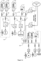
- FIG 1a shows a schematic illustration of an electric power system according to an embodiment of the invention.
- the electric power system is an electric power system of a ship.
- the electric power system comprises a direct voltage rail 101, battery elements, and supply-converters for transferring electric energy from the battery elements to the direct voltage rail.
- three of the battery elements are denoted with figure references 102, 103, and 104, and three of the supply-converters are denoted with figure references 105, 106, and 107.
- the electric power system comprises load-converters for converting the direct voltage of the direct voltage rail 101 into voltages suitable for loads of the electric power system.
- the loads of the electric power system comprise a propulsion system, bow thruster motors, and an alternating voltage network of the ship.
- the load-converters comprise inverters for converting the direct voltage of the direct voltage rail into alternating voltages suitable for the loads of the electric power system.
- the electric power system comprises over-current protectors connected between the direct voltage rail 101 and each of the one or more supply-converters and other over-current protectors connected between the direct voltage rail 101 and each of the one or more load-converters.
- FIG 1a three of the over-current protectors connected between the direct voltage rail 101 and the supply-converters are denoted with figure references 108, 109, and 110, and three of the over-current protectors connected between the direct voltage rail 101 and the load-converters are denoted with figure references 114, 115, and 116.
- Each over-current protector can be for example a fuse or a relay switch responsive to current exceeding a pre-determined limit.
- the electric power system further comprises a capacitor system 117 connected to the direct voltage rail 101.
- the capacitor system 117 may comprise for example one or more high-capacitance electric double layer capacitors "EDLC" which are also called “super capacitors".
- the capacitance of the capacitor system 117 is advantageously at least 0.1 F, more advantageously at least 1 F, and yet more advantageously at least 10 F.
- the capacitor system 117 is capable of supplying fault current that is sufficient to switch an appropriate one of the above-mentioned over-current protectors into a non-conductive state in response to a fault causing a voltage drop at an electrical node connected to the direct voltage rail via the one of the over-current protectors.
- the capacitor system 117 supplies fault current through the over-current protector 114 so that the over-current protector 114 is switched into the non-conductive state and, as a corollary, a part 133 of the electric power system is separated from the rest of the electric power system.
- the capacitor system 117 is connected to the direct voltage rail 101 via an over-current protector 134.
- the current limit of the over-current protector 134 is sufficiently higher than the current limit of each of the over-current protectors 108-110 and 114-116 in order to achieve a selective protection.
- the exemplifying electric power system illustrated in figure 1a comprises another direct voltage rail 126 so that the direct voltage rails 101 and 126 of the electric power system are connected to each other via over-current protectors 127 and 135.
- the portions of the electric power system connected to different ones of the direct voltage rails are advantageously operable independently of each other in order to improve the operational reliability of the electric power system.
- the electric power system comprises another capacitor system 128 connected to the direct voltage rail 127 and capable of supplying fault current in the same way as the above-mentioned capacitor system 117.
- the exemplifying electric power system illustrated in figure 1a comprises charging converters 121 and 122 for receiving electric energy from an external power network 136 and for supplying the electric energy to the direct voltage rails 101 and 126 via over-current protectors 123 and 137.
- the electric power system comprises means for charging the battery elements with the electric energy received from the power network 136.
- the supply-converters can be provided with components and control systems for enabling the supply-converters to transfer electric energy from the direct voltage rails to the battery elements. It is, however, also possible that the electric power system comprises separate converters for charging the battery elements.
- Figure 1b illustrates the main circuit of the supply-converter 105 for transferring electric energy from the battery element 102 to the direct voltage rail 101.
- the other supply-converters can be similar to the supply-converter 105.
- the main circuit of the supply-converter 105 comprises an inductor coil 118 whose first pole is connected to the battery element 102.
- the main circuit comprises a first controllable switch 119 between the ground and the second pole of the inductor coil 118.
- the first controllable switch 119 can be for example an insulated gate bipolar transistor "IGBT", a gate turn-off thyristor "GTO", a bipolar transistor, or a field-effect transistor "FET”.
- the main circuit of the supply-converter 105 comprises a first unidirectionally conductive component 120 for providing a path for electric current from the inductor coil 118 towards the direct voltage rail 101 in response to a situation in which the first controllable switch 119 is in a non-conductive state.
- the first unidirectionally conductive component 120 can be for example a diode.
- the supply-converter 105 is a voltage-increasing converter, i.e. a boost-converter, capable of transferring electric energy from the battery element 102 to the direct voltage rail 101 in a controlled way when the voltage V DC BAT of the battery element is smaller than the voltage V DC RAIL of the direct voltage rail 101.
- the supply-converter 105 further comprises components for enabling the supply-converter to transfer electric energy from the direct voltage rail 101 to the battery element 102 so as to charge the battery element 102.
- the main circuit of the supply-converter 105 comprises a second controllable switch 124 for conducting electric current arriving from the direct voltage rail 110 to the second pole of the inductor coil 118.
- the second controllable switch 124 can be for example an insulated gate bipolar transistor "IGBT", a gate turn-off thyristor "GTO", a bipolar transistor, or a field-effect transistor "FET”.
- the main circuit of the supply-converter 105 comprises a second unidirectionally conductive component 125 for providing a path for electric current from the ground to the second pole of the inductor coil 118 in response to a situation in which the second controllable switch 124 is in a non-conductive state.
- the second unidirectionally conductive component 125 can be for example a diode.
- the supply-converter 105 is capable of charging the battery element 102 by transferring electric energy from the direct voltage rail 101 to the battery element 102 in a controlled way when the voltage V DC BAT of the battery element is smaller than the voltage V DC RAIL of the direct voltage rail 101.
- the first and second controllable switches 119 and 124 are IGBTs or metal oxide semiconductor field effect transistors "MOSFET"
- the first and second unidirectionally conductive components 120 and 125 can be body diodes of the IGBTs or the MOSFETs.
- Each of the supply-converters and each of the load-converters of the electric power system may comprise a controller for controlling the operation of the converter under consideration. It is also possible that a single controller is configured to control many converters.
- a controller can be implemented with one or more processor circuits each of which can be a programmable processor circuit provided with appropriate software, a dedicated hardware processor such as for example an application specific integrated circuit "ASIC", or a configurable hardware processor such as for example a field programmable gate array "FPGA”.
- each controller may comprise one or more memory circuits. The controllers are not shown in figures 1a and 1b .
Landscapes
- Engineering & Computer Science (AREA)
- Power Engineering (AREA)
- Transportation (AREA)
- Mechanical Engineering (AREA)
- Life Sciences & Earth Sciences (AREA)
- Sustainable Development (AREA)
- Sustainable Energy (AREA)
- Dc-Dc Converters (AREA)
- Inverter Devices (AREA)
- Charge And Discharge Circuits For Batteries Or The Like (AREA)
Claims (10)
- Stromversorgungssystem, umfassend:- eine Gleichspannungsschiene (101),- ein oder mehrere Batterieelemente (102 - 104),- einen oder mehrere Speiseumrichter (105 - 107) zum Übertragen elektrischer Energie von dem einen oder den mehreren Batterieelementen zu der Gleichspannungsschiene, wobei jeder Speiseumrichter mit einem des einen oder der mehreren Batterieelemente verbunden ist,- einen oder mehrere Lastumrichter (111 - 113) zum Umrichten von Gleichspannung der Gleichspannungsschiene in Spannungen, die für eine oder mehrere Lasten des Stromversorgungssystems geeignet sind, und- erste Überstromschutzeinrichtungen (108 - 110, 114 - 116), die zwischen der Gleichspannungsschiene und jedem des einen oder der mehreren Speiseumrichter und zwischen der Gleichspannungsschiene und jedem des einen oder der mehreren Lastumrichter geschaltet sind,dadurch gekennzeichnet, dass das Stromversorgungssystem ferner ein Kondensatorsystem (117) umfasst, das über eine zweite Überstromschutzeinrichtung (134) mit der Gleichspannungsschiene verbunden ist und einen oder mehrere Kondensatoren umfasst, wobei das Kondensatorsystem dazu fähig ist, Fehlerstrom zum Schalten einer der ersten Überstromschutzeinrichtungen in einen nichtleitenden Zustand als Reaktion auf einen Fehler, der einen Spannungsabfall an einem elektrischen Knoten, der über die eine der ersten Überstromschutzeinrichtungen mit der Gleichstromschiene verbunden ist, verursacht, zuzuführen, wobei eine Stromgrenze der zweiten Überstromschutzeinrichtung höher als eine Stromgrenze jeder der ersten Überstromschutzeinrichtungen ist.
- Stromversorgungssystem nach Anspruch 1, wobei der eine oder die mehreren Lastumrichter (111 - 113) einen oder mehrere Wechselrichter zum Umrichten der Gleichspannung der Gleichspannungsschiene in Wechselspannungen, die für eine oder mehrere der Lasten des Stromversorgungssystems geeignet sind, umfasst.
- Stromversorgungssystem nach Anspruch 1 oder 2, wobei jeder Speiseumrichter Folgendes umfasst:- eine Induktionsspule (118), deren erster Pol mit dem entsprechenden der Batterieelemente (102) verbunden ist,- einen ersten steuerbaren Schalter (119) zwischen einer Masse und einem zweiten Pol der Induktionsspule und- eine erste in einer Richtung leitende Komponente (120) zum Bereitstellen eines Weges für elektrischen Strom von der Induktionsspule hin zu der Gleichspannungsschiene (101) als Reaktion auf eine Situation, in welcher der erste steuerbare Schalter sich in einem nichtleitenden Zustand befindet.
- Stromversorgungssystem nach Anspruch 3, wobei jeder des einen oder der mehreren Speiseumrichter ferner die folgenden Komponenten zum Befähigen des Speiseumrichters dazu, elektrische Energie von der Gleichspannungsschiene zu dem entsprechenden der Batterieelemente zu übertragen, umfasst:- einen zweiten steuerbaren Schalter (124) zum Leiten von elektrischem Strom, der von der Gleichspannungsschiene ankommt, zu dem zweiten Pol der Induktionsspule und- eine zweite in einer Richtung leitende Komponente (125) zum Bereitstellen eines Weges für elektrischen Strom von der Masse zu dem zweiten Pol der Induktionsspule als Reaktion auf eine Situation, in welcher der zweite steuerbare Schalter sich in einem nichtleitenden Zustand befindet.
- Stromversorgungssystem nach einem der Ansprüche 1 - 4, wobei das Stromversorgungssystem einen Ladeumrichter (121) zum Empfangen von elektrischer Energie aus einem externen Stromnetz und zum Zuführen der elektrischen Energie zu der Gleichspannungsschiene über eine dritte Überstromschutzeinrichtung (123) umfasst.
- Stromversorgungssystem nach einem der Ansprüche 1 - 5, wobei das Stromversorgungssystem wenigstens eine weitere Gleichspannungsschiene (126) umfasst, sodass die Gleichspannungsschienen des Stromversorgungssystems über eine oder mehrere vierte Überstromschutzeinrichtungen (127) miteinander verbunden sind.
- Stromversorgungssystem nach Anspruch 6, wobei das Stromversorgungssystem wenigstens ein weiteres Kondensatorsystem (128) umfasst, das einen oder mehrere Kondensatoren umfasst und mit der wenigstens einen weiteren Gleichspannungsschiene (127) verbunden ist.
- Stromversorgungssystem nach einem der Ansprüche 1 - 7, wobei das Kondensatorsystem einen oder mehrere Doppelschichtkondensatoren umfasst.
- Stromversorgungssystem nach einem der Ansprüche 1 - 8, wobei wenigstens eine der ersten und zweiten Überstromschutzeinrichtungen eine Sicherung ist.
- Schiff, das ein Stromversorgungssystem nach einem der Ansprüche 1 - 9 umfasst.
Priority Applications (6)
| Application Number | Priority Date | Filing Date | Title |
|---|---|---|---|
| FIEP16154410.1T FI3203595T3 (fi) | 2016-02-05 | 2016-02-05 | Sähkövoimajärjestelmä |
| EP16154410.1A EP3203595B1 (de) | 2016-02-05 | 2016-02-05 | Stromversorgungssystem |
| KR1020170014101A KR102728883B1 (ko) | 2016-02-05 | 2017-01-31 | 전력 시스템 |
| TW106103670A TWI726050B (zh) | 2016-02-05 | 2017-02-03 | 電力系統以及包括其之船舶 |
| CN201710135569.2A CN107046273B (zh) | 2016-02-05 | 2017-02-04 | 电力系统 |
| US15/425,096 US10218271B2 (en) | 2016-02-05 | 2017-02-06 | Electric power system |
Applications Claiming Priority (1)
| Application Number | Priority Date | Filing Date | Title |
|---|---|---|---|
| EP16154410.1A EP3203595B1 (de) | 2016-02-05 | 2016-02-05 | Stromversorgungssystem |
Publications (2)
| Publication Number | Publication Date |
|---|---|
| EP3203595A1 EP3203595A1 (de) | 2017-08-09 |
| EP3203595B1 true EP3203595B1 (de) | 2025-04-02 |
Family
ID=55353015
Family Applications (1)
| Application Number | Title | Priority Date | Filing Date |
|---|---|---|---|
| EP16154410.1A Active EP3203595B1 (de) | 2016-02-05 | 2016-02-05 | Stromversorgungssystem |
Country Status (6)
| Country | Link |
|---|---|
| US (1) | US10218271B2 (de) |
| EP (1) | EP3203595B1 (de) |
| KR (1) | KR102728883B1 (de) |
| CN (1) | CN107046273B (de) |
| FI (1) | FI3203595T3 (de) |
| TW (1) | TWI726050B (de) |
Families Citing this family (10)
| Publication number | Priority date | Publication date | Assignee | Title |
|---|---|---|---|---|
| US10910876B2 (en) * | 2016-09-30 | 2021-02-02 | Toshiba Mitsubishi-Electric Industrial Systems Corporation | Uninterruptible power supply device |
| EP3675301A1 (de) * | 2018-12-27 | 2020-07-01 | Siemens Aktiengesellschaft | Elektrisches koppeln von wenigstens zwei an einem energieversorgungsnetz angeschlossenen elektrischen einrichtungen mit wenigstens einer am energieversorgungsnetz angeschlossenen elektrischen energiequelle |
| EP4686065A3 (de) * | 2019-04-02 | 2026-03-25 | G.D Societa' Per Azioni | Automatische maschine und zugehöriges verfahren zur steuerung der herstellung oder verpackung von rauch-, hygiene-, lebensmittel- oder pharmazeutischen produkten |
| CN110350500B (zh) * | 2019-08-13 | 2021-08-27 | 南京南瑞继保电气有限公司 | 伪双极直流配电网保护方法、装置、系统、设备及介质 |
| CN110492453B (zh) | 2019-09-11 | 2023-01-06 | 阳光电源股份有限公司 | 一种储能系统及其多级短路保护系统 |
| KR102710076B1 (ko) * | 2019-12-23 | 2024-09-26 | 한국전력공사 | 배터리 어레이 및 배터리 스택 |
| FI3985822T3 (fi) * | 2020-10-15 | 2023-12-19 | Danfoss Editron Oy | Sähkövoimajärjestelmä |
| EP4105960A1 (de) * | 2021-06-17 | 2022-12-21 | Siemens Energy Global GmbH & Co. KG | Sicherungseinrichtung für ein elektrisches energieversorgungsnetz |
| CN113659533B (zh) * | 2021-09-10 | 2024-04-12 | 阳光电源股份有限公司 | 功率变换器并联系统和储能系统 |
| KR20230092115A (ko) * | 2021-12-17 | 2023-06-26 | 주식회사 엘지에너지솔루션 | 에너지 저장 시스템 및 에너지 저장 시스템의 접지구조 제어 방법 |
Family Cites Families (12)
| Publication number | Priority date | Publication date | Assignee | Title |
|---|---|---|---|---|
| FR2938234B1 (fr) * | 2008-11-13 | 2010-11-26 | Stx France Cruise Sa | Navire automoteur affecte a la navigation sur une distance de consigne entre un point de depart et un point d'arrivee |
| JP5234179B2 (ja) * | 2009-06-02 | 2013-07-10 | トヨタ自動車株式会社 | 電動車両の電源システムおよびその制御方法 |
| KR100990131B1 (ko) * | 2010-01-26 | 2010-10-29 | 중앙제어 주식회사 | 대기전력 제어 시스템 |
| KR101114115B1 (ko) * | 2010-03-08 | 2012-02-20 | 엘에스산전 주식회사 | 모터 보호 계전기 및 그 제어방법 |
| TWI496384B (zh) * | 2010-12-08 | 2015-08-11 | Univ Nat Taipei Technology | 複合供電系統 |
| GB201102031D0 (en) * | 2011-02-07 | 2011-03-23 | Rolls Royce Plc | Protection system for an electrical power network |
| DK2634885T3 (en) * | 2012-02-29 | 2015-11-23 | Abb Technology Ltd | DC power system with system protection features |
| CN103633722B (zh) * | 2013-11-14 | 2015-12-09 | 哈尔滨工程大学 | 最大充放电电流快速无超调切换控制电路及其控制方法 |
| US9748762B2 (en) * | 2014-03-21 | 2017-08-29 | Abb Schweiz Ag | Method and apparatus for the protection of DC distribution systems |
| CN107210603B (zh) * | 2014-05-04 | 2020-07-14 | Abb瑞士股份有限公司 | 基于转换器的dc配电系统中的故障保护 |
| CN104795881B (zh) * | 2015-05-07 | 2017-09-29 | 王吉武 | 风光互补供电控制器及微电网系统及微电网系统供电方法 |
| CN104935068A (zh) * | 2015-07-07 | 2015-09-23 | 国网电力科学研究院武汉南瑞有限责任公司 | 电动汽车救援车供电系统地面模拟装置 |
-
2016
- 2016-02-05 EP EP16154410.1A patent/EP3203595B1/de active Active
- 2016-02-05 FI FIEP16154410.1T patent/FI3203595T3/fi active
-
2017
- 2017-01-31 KR KR1020170014101A patent/KR102728883B1/ko active Active
- 2017-02-03 TW TW106103670A patent/TWI726050B/zh active
- 2017-02-04 CN CN201710135569.2A patent/CN107046273B/zh active Active
- 2017-02-06 US US15/425,096 patent/US10218271B2/en active Active
Also Published As
| Publication number | Publication date |
|---|---|
| EP3203595A1 (de) | 2017-08-09 |
| TWI726050B (zh) | 2021-05-01 |
| KR102728883B1 (ko) | 2024-11-12 |
| US10218271B2 (en) | 2019-02-26 |
| TW201729505A (zh) | 2017-08-16 |
| US20170229964A1 (en) | 2017-08-10 |
| FI3203595T3 (fi) | 2025-06-25 |
| KR20170093717A (ko) | 2017-08-16 |
| CN107046273A (zh) | 2017-08-15 |
| CN107046273B (zh) | 2019-12-31 |
Similar Documents
| Publication | Publication Date | Title |
|---|---|---|
| EP3203595B1 (de) | Stromversorgungssystem | |
| US10742036B2 (en) | Power converter and an electric power system | |
| US9083274B2 (en) | Power stage precharging and dynamic braking apparatus for multilevel inverter | |
| EP2980944B1 (de) | Gleichstromsystem für marineanwendungen | |
| US8687389B2 (en) | Apparatus having a converter | |
| US9787213B2 (en) | Power cell bypass method and apparatus for multilevel inverter | |
| Maqsood et al. | Integration of Z-source breakers into zonal DC ship power system microgrids | |
| US11509128B2 (en) | Multi-port solid-state circuit breaker apparatuses, systems, and methods | |
| US20190131885A1 (en) | Submodule and electrical arrangement having submodules | |
| US11196338B2 (en) | Semiconductor topologies and devices for soft starting and active fault protection of power converters | |
| EP2980945B1 (de) | Gleichstromsystem für meeresanwendungen | |
| HK1234899B (en) | An electric power system | |
| HK1234899A1 (en) | An electric power system | |
| HK1234899A (en) | An electric power system | |
| US10333389B2 (en) | Converter module for a multi-stage converter and method for operating said converter module | |
| ZA200200025B (en) | Method for protecting power semiconductors of a power converter and converter implementing same. | |
| EP3136538A1 (de) | Zwischenschaltkreissystem |
Legal Events
| Date | Code | Title | Description |
|---|---|---|---|
| PUAI | Public reference made under article 153(3) epc to a published international application that has entered the european phase |
Free format text: ORIGINAL CODE: 0009012 |
|
| STAA | Information on the status of an ep patent application or granted ep patent |
Free format text: STATUS: THE APPLICATION HAS BEEN PUBLISHED |
|
| AK | Designated contracting states |
Kind code of ref document: A1 Designated state(s): AL AT BE BG CH CY CZ DE DK EE ES FI FR GB GR HR HU IE IS IT LI LT LU LV MC MK MT NL NO PL PT RO RS SE SI SK SM TR |
|
| AX | Request for extension of the european patent |
Extension state: BA ME |
|
| STAA | Information on the status of an ep patent application or granted ep patent |
Free format text: STATUS: REQUEST FOR EXAMINATION WAS MADE |
|
| REG | Reference to a national code |
Ref country code: HK Ref legal event code: DE Ref document number: 1234899 Country of ref document: HK |
|
| 17P | Request for examination filed |
Effective date: 20180123 |
|
| RBV | Designated contracting states (corrected) |
Designated state(s): AL AT BE BG CH CY CZ DE DK EE ES FI FR GB GR HR HU IE IS IT LI LT LU LV MC MK MT NL NO PL PT RO RS SE SI SK SM TR |
|
| RAP1 | Party data changed (applicant data changed or rights of an application transferred) |
Owner name: DANFOSS MOBILE ELECTRIFICATION OY |
|
| STAA | Information on the status of an ep patent application or granted ep patent |
Free format text: STATUS: EXAMINATION IS IN PROGRESS |
|
| 17Q | First examination report despatched |
Effective date: 20210225 |
|
| P01 | Opt-out of the competence of the unified patent court (upc) registered |
Effective date: 20230713 |
|
| RAP1 | Party data changed (applicant data changed or rights of an application transferred) |
Owner name: DANFOSS A/S |
|
| GRAP | Despatch of communication of intention to grant a patent |
Free format text: ORIGINAL CODE: EPIDOSNIGR1 |
|
| STAA | Information on the status of an ep patent application or granted ep patent |
Free format text: STATUS: GRANT OF PATENT IS INTENDED |
|
| RIC1 | Information provided on ipc code assigned before grant |
Ipc: H02H 7/26 20060101ALI20241114BHEP Ipc: H02H 7/12 20060101ALI20241114BHEP Ipc: H02H 3/20 20060101ALI20241114BHEP Ipc: H02H 3/087 20060101ALI20241114BHEP Ipc: H02H 1/06 20060101AFI20241114BHEP |
|
| INTG | Intention to grant announced |
Effective date: 20241126 |
|
| GRAS | Grant fee paid |
Free format text: ORIGINAL CODE: EPIDOSNIGR3 |
|
| GRAA | (expected) grant |
Free format text: ORIGINAL CODE: 0009210 |
|
| STAA | Information on the status of an ep patent application or granted ep patent |
Free format text: STATUS: THE PATENT HAS BEEN GRANTED |
|
| AK | Designated contracting states |
Kind code of ref document: B1 Designated state(s): AL AT BE BG CH CY CZ DE DK EE ES FI FR GB GR HR HU IE IS IT LI LT LU LV MC MK MT NL NO PL PT RO RS SE SI SK SM TR |
|
| REG | Reference to a national code |
Ref country code: GB Ref legal event code: FG4D |
|
| REG | Reference to a national code |
Ref country code: SE Ref legal event code: TRGR |
|
| REG | Reference to a national code |
Ref country code: CH Ref legal event code: EP |
|
| REG | Reference to a national code |
Ref country code: IE Ref legal event code: FG4D |
|
| REG | Reference to a national code |
Ref country code: DE Ref legal event code: R096 Ref document number: 602016091743 Country of ref document: DE |
|
| REG | Reference to a national code |
Ref country code: FI Ref legal event code: FGE |
|
| REG | Reference to a national code |
Ref country code: NL Ref legal event code: MP Effective date: 20250402 |
|
| PG25 | Lapsed in a contracting state [announced via postgrant information from national office to epo] |
Ref country code: NL Free format text: LAPSE BECAUSE OF FAILURE TO SUBMIT A TRANSLATION OF THE DESCRIPTION OR TO PAY THE FEE WITHIN THE PRESCRIBED TIME-LIMIT Effective date: 20250402 |
|
| REG | Reference to a national code |
Ref country code: AT Ref legal event code: MK05 Ref document number: 1782278 Country of ref document: AT Kind code of ref document: T Effective date: 20250402 |
|
| PG25 | Lapsed in a contracting state [announced via postgrant information from national office to epo] |
Ref country code: PT Free format text: LAPSE BECAUSE OF FAILURE TO SUBMIT A TRANSLATION OF THE DESCRIPTION OR TO PAY THE FEE WITHIN THE PRESCRIBED TIME-LIMIT Effective date: 20250804 Ref country code: ES Free format text: LAPSE BECAUSE OF FAILURE TO SUBMIT A TRANSLATION OF THE DESCRIPTION OR TO PAY THE FEE WITHIN THE PRESCRIBED TIME-LIMIT Effective date: 20250402 |
|
| REG | Reference to a national code |
Ref country code: LT Ref legal event code: MG9D |
|
| PG25 | Lapsed in a contracting state [announced via postgrant information from national office to epo] |
Ref country code: GR Free format text: LAPSE BECAUSE OF FAILURE TO SUBMIT A TRANSLATION OF THE DESCRIPTION OR TO PAY THE FEE WITHIN THE PRESCRIBED TIME-LIMIT Effective date: 20250703 |
|
| PG25 | Lapsed in a contracting state [announced via postgrant information from national office to epo] |
Ref country code: PL Free format text: LAPSE BECAUSE OF FAILURE TO SUBMIT A TRANSLATION OF THE DESCRIPTION OR TO PAY THE FEE WITHIN THE PRESCRIBED TIME-LIMIT Effective date: 20250402 |
|
| PG25 | Lapsed in a contracting state [announced via postgrant information from national office to epo] |
Ref country code: BG Free format text: LAPSE BECAUSE OF FAILURE TO SUBMIT A TRANSLATION OF THE DESCRIPTION OR TO PAY THE FEE WITHIN THE PRESCRIBED TIME-LIMIT Effective date: 20250402 |
|
| PG25 | Lapsed in a contracting state [announced via postgrant information from national office to epo] |
Ref country code: HR Free format text: LAPSE BECAUSE OF FAILURE TO SUBMIT A TRANSLATION OF THE DESCRIPTION OR TO PAY THE FEE WITHIN THE PRESCRIBED TIME-LIMIT Effective date: 20250402 |
|
| PG25 | Lapsed in a contracting state [announced via postgrant information from national office to epo] |
Ref country code: AT Free format text: LAPSE BECAUSE OF FAILURE TO SUBMIT A TRANSLATION OF THE DESCRIPTION OR TO PAY THE FEE WITHIN THE PRESCRIBED TIME-LIMIT Effective date: 20250402 |
|
| PG25 | Lapsed in a contracting state [announced via postgrant information from national office to epo] |
Ref country code: RS Free format text: LAPSE BECAUSE OF FAILURE TO SUBMIT A TRANSLATION OF THE DESCRIPTION OR TO PAY THE FEE WITHIN THE PRESCRIBED TIME-LIMIT Effective date: 20250702 |
|
| PG25 | Lapsed in a contracting state [announced via postgrant information from national office to epo] |
Ref country code: IS Free format text: LAPSE BECAUSE OF FAILURE TO SUBMIT A TRANSLATION OF THE DESCRIPTION OR TO PAY THE FEE WITHIN THE PRESCRIBED TIME-LIMIT Effective date: 20250802 |
|
| PG25 | Lapsed in a contracting state [announced via postgrant information from national office to epo] |
Ref country code: LV Free format text: LAPSE BECAUSE OF FAILURE TO SUBMIT A TRANSLATION OF THE DESCRIPTION OR TO PAY THE FEE WITHIN THE PRESCRIBED TIME-LIMIT Effective date: 20250402 |
|
| REG | Reference to a national code |
Ref country code: DE Ref legal event code: R097 Ref document number: 602016091743 Country of ref document: DE |
|
| PG25 | Lapsed in a contracting state [announced via postgrant information from national office to epo] |
Ref country code: SM Free format text: LAPSE BECAUSE OF FAILURE TO SUBMIT A TRANSLATION OF THE DESCRIPTION OR TO PAY THE FEE WITHIN THE PRESCRIBED TIME-LIMIT Effective date: 20250402 Ref country code: DK Free format text: LAPSE BECAUSE OF FAILURE TO SUBMIT A TRANSLATION OF THE DESCRIPTION OR TO PAY THE FEE WITHIN THE PRESCRIBED TIME-LIMIT Effective date: 20250402 |
|
| PGFP | Annual fee paid to national office [announced via postgrant information from national office to epo] |
Ref country code: FR Payment date: 20251231 Year of fee payment: 11 |
|
| PG25 | Lapsed in a contracting state [announced via postgrant information from national office to epo] |
Ref country code: CZ Free format text: LAPSE BECAUSE OF FAILURE TO SUBMIT A TRANSLATION OF THE DESCRIPTION OR TO PAY THE FEE WITHIN THE PRESCRIBED TIME-LIMIT Effective date: 20250402 |
|
| PG25 | Lapsed in a contracting state [announced via postgrant information from national office to epo] |
Ref country code: EE Free format text: LAPSE BECAUSE OF FAILURE TO SUBMIT A TRANSLATION OF THE DESCRIPTION OR TO PAY THE FEE WITHIN THE PRESCRIBED TIME-LIMIT Effective date: 20250402 |
|
| PG25 | Lapsed in a contracting state [announced via postgrant information from national office to epo] |
Ref country code: SK Free format text: LAPSE BECAUSE OF FAILURE TO SUBMIT A TRANSLATION OF THE DESCRIPTION OR TO PAY THE FEE WITHIN THE PRESCRIBED TIME-LIMIT Effective date: 20250402 Ref country code: RO Free format text: LAPSE BECAUSE OF FAILURE TO SUBMIT A TRANSLATION OF THE DESCRIPTION OR TO PAY THE FEE WITHIN THE PRESCRIBED TIME-LIMIT Effective date: 20250402 |
|
| PLBE | No opposition filed within time limit |
Free format text: ORIGINAL CODE: 0009261 |
|
| STAA | Information on the status of an ep patent application or granted ep patent |
Free format text: STATUS: NO OPPOSITION FILED WITHIN TIME LIMIT |
|
| REG | Reference to a national code |
Ref country code: CH Ref legal event code: L10 Free format text: ST27 STATUS EVENT CODE: U-0-0-L10-L00 (AS PROVIDED BY THE NATIONAL OFFICE) Effective date: 20260211 |
|
| 26N | No opposition filed |
Effective date: 20260105 |
|
| PGFP | Annual fee paid to national office [announced via postgrant information from national office to epo] |
Ref country code: SE Payment date: 20260105 Year of fee payment: 11 |
|
| PGFP | Annual fee paid to national office [announced via postgrant information from national office to epo] |
Ref country code: GB Payment date: 20260106 Year of fee payment: 11 |
|
| PGFP | Annual fee paid to national office [announced via postgrant information from national office to epo] |
Ref country code: NO Payment date: 20260211 Year of fee payment: 11 Ref country code: DE Payment date: 20260102 Year of fee payment: 11 |
|
| PGFP | Annual fee paid to national office [announced via postgrant information from national office to epo] |
Ref country code: FI Payment date: 20260213 Year of fee payment: 11 Ref country code: IT Payment date: 20260122 Year of fee payment: 11 |