EP3203596A1 - Verfahren und anlage zur stromerzeugung aus erneuerbaren energiequellen mit regulierung der gelieferten stromstärke - Google Patents
Verfahren und anlage zur stromerzeugung aus erneuerbaren energiequellen mit regulierung der gelieferten stromstärke Download PDFInfo
- Publication number
- EP3203596A1 EP3203596A1 EP17154669.0A EP17154669A EP3203596A1 EP 3203596 A1 EP3203596 A1 EP 3203596A1 EP 17154669 A EP17154669 A EP 17154669A EP 3203596 A1 EP3203596 A1 EP 3203596A1
- Authority
- EP
- European Patent Office
- Prior art keywords
- power
- hydroelectric
- station
- power station
- solar power
- Prior art date
- Legal status (The legal status is an assumption and is not a legal conclusion. Google has not performed a legal analysis and makes no representation as to the accuracy of the status listed.)
- Granted
Links
Images


Classifications
-
- H—ELECTRICITY
- H02—GENERATION; CONVERSION OR DISTRIBUTION OF ELECTRIC POWER
- H02J—ELECTRIC POWER NETWORKS; CIRCUIT ARRANGEMENTS OR SYSTEMS FOR SUPPLYING OR DISTRIBUTING ELECTRIC POWER; SYSTEMS FOR STORING ELECTRIC ENERGY
- H02J3/00—Circuit arrangements for AC mains or AC distribution networks
- H02J3/04—Arrangements for connecting networks of the same frequency but supplied from different sources
-
- H—ELECTRICITY
- H02—GENERATION; CONVERSION OR DISTRIBUTION OF ELECTRIC POWER
- H02J—ELECTRIC POWER NETWORKS; CIRCUIT ARRANGEMENTS OR SYSTEMS FOR SUPPLYING OR DISTRIBUTING ELECTRIC POWER; SYSTEMS FOR STORING ELECTRIC ENERGY
- H02J3/00—Circuit arrangements for AC mains or AC distribution networks
- H02J3/38—Arrangements for feeding a single network from two or more generators or sources in parallel; Arrangements for feeding already energised networks from additional generators or sources in parallel
- H02J3/381—Dispersed generators
-
- H—ELECTRICITY
- H02—GENERATION; CONVERSION OR DISTRIBUTION OF ELECTRIC POWER
- H02J—ELECTRIC POWER NETWORKS; CIRCUIT ARRANGEMENTS OR SYSTEMS FOR SUPPLYING OR DISTRIBUTING ELECTRIC POWER; SYSTEMS FOR STORING ELECTRIC ENERGY
- H02J3/00—Circuit arrangements for AC mains or AC distribution networks
- H02J3/38—Arrangements for feeding a single network from two or more generators or sources in parallel; Arrangements for feeding already energised networks from additional generators or sources in parallel
- H02J3/46—Controlling the sharing of generated power between the generators, sources or networks
-
- H—ELECTRICITY
- H02—GENERATION; CONVERSION OR DISTRIBUTION OF ELECTRIC POWER
- H02J—ELECTRIC POWER NETWORKS; CIRCUIT ARRANGEMENTS OR SYSTEMS FOR SUPPLYING OR DISTRIBUTING ELECTRIC POWER; SYSTEMS FOR STORING ELECTRIC ENERGY
- H02J2101/00—Supply or distribution of decentralised, dispersed or local electric power generation
- H02J2101/20—Dispersed power generation using renewable energy sources
-
- H—ELECTRICITY
- H02—GENERATION; CONVERSION OR DISTRIBUTION OF ELECTRIC POWER
- H02J—ELECTRIC POWER NETWORKS; CIRCUIT ARRANGEMENTS OR SYSTEMS FOR SUPPLYING OR DISTRIBUTING ELECTRIC POWER; SYSTEMS FOR STORING ELECTRIC ENERGY
- H02J2101/00—Supply or distribution of decentralised, dispersed or local electric power generation
- H02J2101/20—Dispersed power generation using renewable energy sources
- H02J2101/22—Solar energy
- H02J2101/24—Photovoltaics
-
- H—ELECTRICITY
- H02—GENERATION; CONVERSION OR DISTRIBUTION OF ELECTRIC POWER
- H02J—ELECTRIC POWER NETWORKS; CIRCUIT ARRANGEMENTS OR SYSTEMS FOR SUPPLYING OR DISTRIBUTING ELECTRIC POWER; SYSTEMS FOR STORING ELECTRIC ENERGY
- H02J2101/00—Supply or distribution of decentralised, dispersed or local electric power generation
- H02J2101/40—Hybrid power plants, i.e. a plurality of different generation technologies being operated at one power plant
-
- H—ELECTRICITY
- H02—GENERATION; CONVERSION OR DISTRIBUTION OF ELECTRIC POWER
- H02J—ELECTRIC POWER NETWORKS; CIRCUIT ARRANGEMENTS OR SYSTEMS FOR SUPPLYING OR DISTRIBUTING ELECTRIC POWER; SYSTEMS FOR STORING ELECTRIC ENERGY
- H02J3/00—Circuit arrangements for AC mains or AC distribution networks
- H02J3/34—Arrangements for transfer of electric power between networks of substantially different frequency
-
- Y—GENERAL TAGGING OF NEW TECHNOLOGICAL DEVELOPMENTS; GENERAL TAGGING OF CROSS-SECTIONAL TECHNOLOGIES SPANNING OVER SEVERAL SECTIONS OF THE IPC; TECHNICAL SUBJECTS COVERED BY FORMER USPC CROSS-REFERENCE ART COLLECTIONS [XRACs] AND DIGESTS
- Y02—TECHNOLOGIES OR APPLICATIONS FOR MITIGATION OR ADAPTATION AGAINST CLIMATE CHANGE
- Y02E—REDUCTION OF GREENHOUSE GAS [GHG] EMISSIONS, RELATED TO ENERGY GENERATION, TRANSMISSION OR DISTRIBUTION
- Y02E10/00—Energy generation through renewable energy sources
- Y02E10/50—Photovoltaic [PV] energy
- Y02E10/56—Power conversion systems, e.g. maximum power point trackers
Definitions
- the invention relates to a method and an installation for generating electricity from renewable energies, with regulation of the power supplied.
- This public network is powered by a set of very large power plants, such as fossil-fueled power plants, coal, lignite or petroleum, or nuclear energy, as well as power stations. hydraulics using the energy of a waterfall in mountainous regions, or that of a river such as the Rhone or the Rhine, in factories along the water.
- the electric power thus produced is distributed throughout the territory by the public distribution network, consisting of a set of connected lines for the transmission of current at higher or lower voltage.
- micro- or mini-hydropower plants which can be built over a large part of the country, especially in temperate countries where rainfall is relatively high.
- the document FR-A-2,983,921 discloses an energy production plant comprising a tank opening, at its base, in a supply line of a turbine producing an electric power, provided with means for adjusting the water passage section and therefore, the power produced.
- the installation also includes a pump for discharging water from an external source into the tank in order to maintain the level of water. the water.
- This pump is powered by electrical energy produced from renewable energy, for example a wind turbine or photovoltaic panels.
- the means for adjusting the section of the supply duct of the turbine are controlled according to the power produced, in order to maintain it to a set value corresponding to the needs of the network supplied by the installation.
- Solar energy on the other hand, has fewer disadvantages for the environment because it makes it possible to produce electricity, by photoelectric effect, by means of photovoltaic modules constituting flat panels of small thickness and, consequently, of height. scaled down.
- a solar power plant therefore comprises a set of photovoltaic modules connected to one another and connected to the distribution network by means of transformation means for producing an alternating current having characteristics adapted to the operating conditions of this network.
- Such installations can have very varied powers which depend on the number of modules and the surface covered.
- the modules can be divided into several sections taking into account the relief of the ground and, because of the rather small height of the photovoltaic panels, it is possible to hide them behind a simple curtain of trees .
- the plant operator must normally undertake to keep the power injected into the network at a substantially stable value, the purchase price being reduced if this commitment is not respected.
- the object of the invention is to overcome these drawbacks by means of a new method making it possible to compensate for the unavoidable variations in energy efficiency of a solar power station, in order to inject into the distribution network a relatively stable electrical power, respecting the commitments made. by the operator.
- the invention therefore relates, in a general manner, to a method for producing an electric power from renewable energies, in an installation comprising at least two devices made close to each other on a territory, for the transformation of at least two renewable energies into electrical power suitable for being injected into an electrical network, respectively a first device for transforming the energy of the solar radiation and a second device for transforming the hydraulic energy, comprising a hydroelectric generating unit fed from a water reservoir by at least one water flow line, and means for adjusting the electric power supplied by said second transformation device.
- the electrical network into which the powers provided by the two renewable energy transformation devices, respectively, is injected is a general electricity distribution network in the territory and the first transformation device is a central power station.
- solar generator having a nominal power corresponding, at least, to the operator's commitments and supplying a base current which is converted into an alternating current having characteristics adapted to the general distribution network, said solar power station being connected to a connected delivery station to the general distribution network for injecting, into it, said adapted current
- the second transformation device is a hydroelectric plant comprising a production unit powered by at least one pipe flow from a supply of water fed, itself, by at least one stream and located above the level of the solar power station, in the vicinity thereof, and said hydroelectric power station is capable of producing a nominal power of the same order as the solar power station and is connected, in parallel, to the same delivery station as this one, for the injection, into the general network, of the electric current produced by the said hydroelectric power station , after transformation into an alternating current having characteristics adapted to the general distribution network
- the solar power plant is of a type comprising a set of photovoltaic panels capable of providing a nominal power of at least 5 MW.
- the solar power plant is of the thermodynamic type for transforming the energy radiated by the sun into heat, and the latter into mechanical and electrical energy.
- the water reserve has a sufficient capacity to maintain, at all times and under all circumstances, the global power injected into the general distribution network at a relatively stable value corresponding to the commitments made. by the operator in respect of the electricity distributor.
- the water reserve has a variable volume, allowing to accumulate, during periods of strong sunlight, a sufficient amount of water for the production, by the hydroelectric group, of a power capable of compensate for a reduction in the output of the solar power plant during periods of little or no sunlight, in order to keep the overall electrical power injected into the distribution network at a relatively stable level.
- the invention also covers an installation for implementing the method comprising at least two devices made close to each other on a territory, for the transformation of at least two renewable energies into electrical power capable of being injected into an electrical network, respectively a first device for transforming the energy of the solar radiation and a second device for hydraulic energy conversion comprising a hydroelectric generating unit fed from a water reserve by at least one water flow pipe, and means for adjusting the electrical power supplied by said second water supply device; transformation.
- the electrical network in which the powers supplied by the two renewable energy transformation devices are respectively injected is a general electricity distribution network in the territory
- the first transformation device is a central power station.
- solar generator having a nominal power corresponding, at least, to the operator's commitments and supplying a base current which is converted into an alternating current of characteristics adapted to those of the general network, said solar power station being connected to a connected delivery station to the general network for the injection, permanently therein, of said adapted current
- the second transformation device is a hydroelectric plant comprising a production unit supplied by at least one flow line from a reserve water fed, itself, by at least one stream and located above the level of the solar power station, in the vicinity thereof, said hydroelectric power plant being connected, in parallel, to the same delivery station as the solar power plant, for the injection, into the general network, of the electric current produced by said hydroelectric power plant, after transformation into an alternating current having characteristics adapted to the general distribution network, and the means for adjusting the electric power supplied by the hydroelectric power station are controlled by
- the solar power plant is of the type comprising a set of photovoltaic panels capable of providing an electric power of at least 5 MW.
- the solar power plant is of the thermodynamic type for transforming the energy radiated by the sun into heat, and the latter into mechanical and electrical energy.
- the means for capturing solar energy may also consist of a set of mirrors converging solar radiation to means for producing a gas under pressure capable of operating a turbo-alternator group for the production of an electric current.
- the hydroelectric plant is installed at a relatively small distance from the solar power station to allow the transport of the electric power it provides to the delivery station, without significant loss of energy.
- the hydroelectric generating station comprises at least one dam formed on at least one watercourse and placed in a place making it possible to create a lake for holding water connected to the hydroelectric unit by at least one water pipe. flow and whose capacity may vary according to the power to be supplied and the feed rate by the watercourse, so that the reservoir reservoir forms a reserve of water of variable volume, capable of delivering or accumulate water according to the hydroelectric power required to compensate for the variations in the power supplied by the solar power station.
- the hydroelectric plant comprises at least one large section flow pipe extending between a retaining threshold formed, at a first level, on a stream, above the level of the plant. solar and a hydroelectric group placed at a second level, lower than the first, and the cross section of said flow line is determined, given the distance between the holding threshold and the hydroelectric group, so as to limit a volume of water sufficient to ensure the operation of the hydroelectric plant regardless of the variations in production required, at least a portion of the water reserve then being constituted by the water contained in said flow line.
- this large section flow pipe is made from prefabricated reinforced or prestressed concrete elements and comprises, in cross section, a vault element resting on two side members forming piers. spaced apart having an upper portion connecting to the arch member and a flat base resting on the ground and connecting to a cast-in-place slab to follow the profile of the natural terrain.
- the large section flow line comprises a series of bent sheet metal elements welded one after the other and having their ends welded to waiting profiles sealed in a concrete base. cast in situ, said ends being formed to follow the profile of the natural terrain.
- the installation comprises a buffer system connected to the delivery station and for storing energy or energy. redistribute it to the distribution network in the event of excessive variation of the additional power to be supplied by the hydroelectric power station.
- the buffer system is a flywheel.
- the buffer system is a battery for accumulating at least a portion of the electric power supplied globally by the solar power station and the hydroelectric power station.
- the second renewable energy plant being, then, of a type exploiting the movements. from the sea such as waves, waves, underwater currents or tides.
- FIG. 1 schematically shows a plant 1 for producing electricity by solar energy, comprising, as usually, a set of photovoltaic modules interconnected electrically in series or in parallel and aligned to form a number of panels 11 mounted on frames resting on the ground.
- These panels 11 are connected by connecting cables to junction boxes 12 from which the low voltage direct current produced by the modules is transmitted to inverters placed in a technical room 13 in order to transform the direct current into an alternating current.
- This low voltage alternating current for example 380 V, is transmitted to a transformer station 14 which produces an alternating current having characteristics adapted to the distribution network, for example a voltage of 20,000 volts.
- the high-voltage alternating current thus produced can then be injected into the network in the distribution network 16 via a delivery station 15.
- the set of photovoltaic panels 11 covers a large area that depends on the location possibilities and the production to be provided. We know, for example, that a photovoltaic plant such as that of Sainte Tulle, France, with 70,000 modules and covering an area of about 20 hectares, can provide a nominal power of about 5 MW c (megawatts peak). . These panels 11 are oriented, normally, to the south and inclined by an exposure angle that can vary from 25 to 30 ° depending on the local topography. However, the production capacity obviously depends, on the one hand, on cloud cover and, on the other hand, on the height of the sun and, consequently, on the season and time of day.
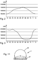
- the figure 2 shows the variations, over one year, in the average value, in kWh, of the energy supplied each month by a solar power station installed in central France. As might be expected, it appears that the amount of energy supplied each month by this plant is maximum between June and September and can reach 1,500,000 kWh, but is reduced to less than 500,000 kWh in winter.
- the generating capacity of a hydroelectric plant which depends on the flow of water to the turbines, is normally higher in winter and, especially, in the spring, when precipitation is high and this is the case. , in particular, for small plants that are often run-of-river and, in any case, do not benefit from a large water reserve, held by a high dam.
- the figure 3 shows the year-on-year variations in the average kWh value of the power supplied each month by a small hydropower plant with an installed capacity of 8 MW and expected for an average annual output of 14 000 000 kWh, with a drop height of 350 m and a storage capacity of approximately 300 000 m 3 . It appears that the amount of energy supplied each month, is maximum between December and April and very reduced between July and October.
- the inventor is also aware that, if we have little control over the energy supplied by the solar power plant, which essentially depends on the radiation captured by the photovoltaic panels, and is therefore not manageable.
- the power supplied by the hydropower station can be regulated permanently, by acting on the flow of water admitted into the turbines. He therefore had the idea that this additional energy provided by the hydropower plant could be adjusted at any moment in order to immediately compensate for the daily variations in the solar energy captured by the photovoltaic panels and thus to maintain at a relatively stable level the global power injected into the network.
- Such a possibility can be illustrated by the diagrams of Figures 4 and 5 .
- a solar power plant In general, a solar power plant is intended to provide a nominal power, also called “peak power" which can be determined by taking into account the site where it is located and its technical characteristics, including the performance of photovoltaic panels and the covered area, the power supplied at each instant varies, obviously, according to the time in the day.
- the figure 4 is a diagram showing the variation, hour by hour, of the optimal power that can be provided by a solar power plant designed for a peak power of 8.5 MW c
- curve A which corresponds to maximum sunshine, in summer, for medium latitude, with a sunrise to At 5 o'clock and sunset around 8 pm
- the production capacity (a) increases gradually from dawn, reaches its maximum value of 8.5 MW at the time of the meridian (12 o'clock in the sun), then decreases until cancel after bedtime.
- this solar power station is associated with a hydroelectric power station whose power can be modified by regulating the water flow admitted into the turbines.
- curve A of the figure 4 corresponds to optimal operating conditions and it is well known that the power produced by solar radiation depends essentially on the meteorological conditions. In fact, even if it increases until about noon and then decreases until sunset, the photovoltaic production capacity will follow a sawtooth course of the type represented by the curve A 'on the figure 6 . But, according to one of the characteristics of the invention, it is possible to continuously measure the power (a ') supplied by the solar power station and to adjust, at any moment, the power supplied by the hydroelectric station to a value ( b ') equal to the difference between the solar power (a') and the desired power (c '), in order to keep the overall power supplied to the network, relatively stable, to this desired value (c').
- the two plants, respectively solar and hydroelectric, used for the implementation of such a method, must be carried out close to each other, that is to say at a distance allowing the transport of the current without noticeable loss of energy.
- photovoltaic panels cover a large area, of the order of several hectares.
- Solar power plants are therefore located, generally, in sparsely populated areas, for example on sunny hills. However, in temperate regions such areas are usually fairly well watered by springs, streams or streams.
- the combination of the two plants thus forms a hybrid complex represented schematically on the figure 1 and comprising, in the vicinity of the solar power station 1 described above, a hydroelectric plant 2 comprising, as usual, a hydroelectric generating unit 21 consisting of one or more hydraulic turbines fed by one or more penstocks 22 from less a water reserve 3 placed at a level higher than that of the turbines 21 and retained by a dam 23 formed across a stream 31 or a supply channel.
- the turbines 21 drive an electrical generator connected to a transformer station 24 provided to produce an alternating current having the same characteristics as the current produced by the transformer station 14 of the solar power station 1. This current is, therefore, adapted to the general network 16 and can thus be applied to the same delivery station 15 which is, therefore, fed in parallel by the solar power station 1 and the hydroelectric station 2.
- the hydroelectric plant 2 is equipped with means for regulating the power of the electric current that it can supply, for example means 25 for controlling the flow of water injected into the turbines 21 through the penstock 22.
- the power (a ') of the electric current produced by the transformation station 14 of the solar power station 1 is continuously measured and a corresponding signal is applied to a control unit 26 which calculates, at each instant, the power (b ') to be supplied by the hydroelectric power station 2 to compensate for the variations in the power (a') and emits a corresponding command order from the water flow control member 25 introduced into the turbines 21, in order to obtain this desired power (b ').
- the overall power (c ' a' + b ') injected into the network 16 by the delivery station 15.
- this reference value corresponds to the commitments made by the operator in the purchase agreement by the distributor of the power produced.
- the production capacity of the hydroelectric power station 2 which depends on rainfall, is normally greater during the bad season and thus allows, during the year, to compensate for the seasonal variation in the generating capacity of the plant solar 1 which depends on sunshine.
- the dam 23 is placed in a place making it possible to carry out a reservoir of water whose capacity can vary according to the production required and the feed rate by the stream 31 but must always be sufficient to cope with all situations, for example a long period of bad weather reducing photovoltaic production or, on the contrary, a period of drought that will permanently reduce water supply.
- the water flow supplying the turbines 21 can be low or zero and it is then possible to let the water level to increase the capacity of the reserve 3 which remains permanently fed by the stream or streams 31 and can then be sufficient, even in periods of low rainfall, to maintain the electric power supplied to the the desired value for a specified period, in order to meet the commitments made by the operator for the supply of relatively stable power to the distribution network.
- photovoltaic energy has a very low inertia and a large amplitude of variation whereas hydropower is, on the contrary, a predictable and adjustable energy, but with greater inertia.
- the speed of regulation of the photovoltaic is of the order of a few seconds whereas a variation of hydroelectric power requires a few minutes.
- a system having a buffer stock role such as, for example, a set of current storage batteries or a flywheel for storing energy or energy. redistribute it in the network 16, in case of excessive variation of the power to be supplied.
- the invention thus makes it possible to flexibly compensate for daily or seasonal variations in the power supplied by the photovoltaic power station in order to respect the operator's commitments by responding to all situations.
- the additional power supplied by the hydroelectric plant can be regulated by adjusting the flow rate of water admitted into the turbines, but it will obviously be possible to use, for this purpose, all the known means for the operation. of such a central.
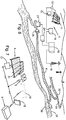
- the distribution of watercourses or the relief of the territory around a solar power plant can make it difficult to build a dam with sufficient holding capacity and placed above the hydroelectric station 2, a height for feeding it by forced pipe. It may, then, be interesting to adopt a provision of the type shown on the figures 8 and 9 , in which the hydroelectric station 2 is fed from a simple threshold over the water 32, formed on the watercourse 31 and connected to the turbine 21 by a pipe of large section 4 can, she -make the water reserve.
- the threshold 32 is not intended to form a reservoir with a large capacity but must have a height only sufficient to divert the water to the inlet 40 of the pipe 4, and the section transverse thereof can be determined, given the distance between the threshold 32 and the turbine 21, so as to limit a volume of water sufficient to operate the hydroelectric plant 2 regardless of the variations in production requested.
- the water reserve is then constituted by the water contained in the feed pipe 4, from the turbine 21 to the level (h) above it.
- the pipe 4 is made from prefabricated reinforced or prestressed concrete elements and comprises, in cross section, a vault element 41 resting on two side members forming spaced apart piers 42 having an arcuate upper curved portion of a circle connecting tangentially to the arch member 4 and a flat base 44 placed on the ground and being connected to a slab 43.
- Such a duct consisting of adjacent prefabricated elements, placed in progress one after the other, may have any length and its inlet 40 may therefore be remote from the central 2.
- prefabrication molds 41,42 elements can be adapted to the position of the element along the pipe, slightly changing the orientation of the lateral sides. It is therefore possible to vary the orientation, in the horizontal or vertical direction, of the elements that are connected by the cast-in-place concrete base 43 and, thus, to follow the profile of the natural terrain without major earthworks, the way indicated on the figure 9 .
- pipe 4 could consist of bent elements 45 of sheet metal, having their ends welded to waiting profiles 46 sealed in a concrete base 47 cast in place.
- profile of the sheet elements 45 it is still possible to adapt the profile of the sheet elements 45 to make curved parts to follow the profile of the natural terrain or the junctions between several pipes.
- a hydroelectric plant is particularly suitable for carrying out the method according to the invention.
- other renewable energies for example marine energies using the movements of waves, currents or tides.
- various wave energy devices which can cause a generator and comprising, for example, blades, propellers, floats or other mechanical devices set in motion by the movement of waves, or tidal turbines powered by currents.
- Such devices can produce, each, a power of the same order as a small wind turbine but several can be distributed along a coast to obtain a significant overall power.
- the coastline is very extensive, especially in France, and some sites, sunny enough, can allow the establishment of a solar power station and, close to it, a hydroelectric plant exploiting marine energy. and whose power can be adjusted to compensate for irregularities in photovoltaic production.
- renewable energies such as thermal energy related to the difference in temperature between the sea surface and deep water, or geothermal energy, could also be used to provide additional power. able to compensate for the daily or seasonal variations of a photovoltaic plant in order to regulate the global power injected into the network.
Landscapes
- Engineering & Computer Science (AREA)
- Power Engineering (AREA)
- Other Liquid Machine Or Engine Such As Wave Power Use (AREA)
Applications Claiming Priority (1)
| Application Number | Priority Date | Filing Date | Title |
|---|---|---|---|
| FR1650934A FR3047523A1 (fr) | 2016-02-05 | 2016-02-05 | Procede et installation de production d'electricite a partir d'energies renouvelables, avec regulation de la puissance fournie |
Publications (2)
| Publication Number | Publication Date |
|---|---|
| EP3203596A1 true EP3203596A1 (de) | 2017-08-09 |
| EP3203596B1 EP3203596B1 (de) | 2019-03-06 |
Family
ID=55590070
Family Applications (1)
| Application Number | Title | Priority Date | Filing Date |
|---|---|---|---|
| EP17154669.0A Active EP3203596B1 (de) | 2016-02-05 | 2017-02-03 | Verfahren und anlage zur stromerzeugung aus erneuerbaren energiequellen mit regulierung der gelieferten stromstärke |
Country Status (3)
| Country | Link |
|---|---|
| EP (1) | EP3203596B1 (de) |
| ES (1) | ES2718768T3 (de) |
| FR (1) | FR3047523A1 (de) |
Cited By (4)
| Publication number | Priority date | Publication date | Assignee | Title |
|---|---|---|---|---|
| EP3422523A1 (de) * | 2017-06-28 | 2019-01-02 | Societe Civile De Brevets Matiere | Verfahren und anlage zur lokalen erzeugung von elektrischer energie |
| CN113824152A (zh) * | 2021-10-26 | 2021-12-21 | 国网新源控股有限公司 | 一种计及水头敏感的变速抽蓄协同风光发电调峰调度方法 |
| US11472307B2 (en) * | 2018-09-26 | 2022-10-18 | Aquanovis Holdings Limited | Dispatchable renewable power supply |
| CN120341996A (zh) * | 2025-06-19 | 2025-07-18 | 广东海洋大学 | 一种基于均衡约束数学规划的配电网重构方法及系统 |
Families Citing this family (3)
| Publication number | Priority date | Publication date | Assignee | Title |
|---|---|---|---|---|
| FR3079244A1 (fr) * | 2018-03-26 | 2019-09-27 | Societe Civile De Brevets Matiere | Procede et installation de mise en reserve d'eau pour une utilisation ulterieure |
| FR3091304B1 (fr) * | 2018-12-28 | 2023-02-24 | Soc Civ De Brevets Matiere | Procédé et système de captage et d’utilisation de l’eau pluviale tombant sur un territoire |
| EP4057469A1 (de) | 2021-03-12 | 2022-09-14 | GE Renewable Technologies | Hybridkraftwerksarchitektur und verfahren zur steuerung |
Citations (5)
| Publication number | Priority date | Publication date | Assignee | Title |
|---|---|---|---|---|
| BE875508A (fr) * | 1979-04-12 | 1979-07-31 | En Nouvelles Et Environnement | Ensemble de production d'energie electrique |
| EP0081402A1 (de) | 1981-11-17 | 1983-06-15 | Marcel Matière | Verfahren zur Herstellung von hohlen Elementen wie etwa Leitungen, Silos oder Bunkern |
| EP0767881A1 (de) | 1994-06-29 | 1997-04-16 | Societe Civile De Brevets Matiere | Flüssigkeitsrohr |
| FR2941574A1 (fr) * | 2009-01-29 | 2010-07-30 | Fabrice Urban | Dispositif de production et de stockage d'energie electrique par panneau solaire photovoltaique |
| FR2983921A1 (fr) | 2011-12-13 | 2013-06-14 | Laurent Barthelemy | Installation de production d'energie |
-
2016
- 2016-02-05 FR FR1650934A patent/FR3047523A1/fr not_active Ceased
-
2017
- 2017-02-03 EP EP17154669.0A patent/EP3203596B1/de active Active
- 2017-02-03 ES ES17154669T patent/ES2718768T3/es active Active
Patent Citations (5)
| Publication number | Priority date | Publication date | Assignee | Title |
|---|---|---|---|---|
| BE875508A (fr) * | 1979-04-12 | 1979-07-31 | En Nouvelles Et Environnement | Ensemble de production d'energie electrique |
| EP0081402A1 (de) | 1981-11-17 | 1983-06-15 | Marcel Matière | Verfahren zur Herstellung von hohlen Elementen wie etwa Leitungen, Silos oder Bunkern |
| EP0767881A1 (de) | 1994-06-29 | 1997-04-16 | Societe Civile De Brevets Matiere | Flüssigkeitsrohr |
| FR2941574A1 (fr) * | 2009-01-29 | 2010-07-30 | Fabrice Urban | Dispositif de production et de stockage d'energie electrique par panneau solaire photovoltaique |
| FR2983921A1 (fr) | 2011-12-13 | 2013-06-14 | Laurent Barthelemy | Installation de production d'energie |
Cited By (6)
| Publication number | Priority date | Publication date | Assignee | Title |
|---|---|---|---|---|
| EP3422523A1 (de) * | 2017-06-28 | 2019-01-02 | Societe Civile De Brevets Matiere | Verfahren und anlage zur lokalen erzeugung von elektrischer energie |
| FR3068531A1 (fr) * | 2017-06-28 | 2019-01-04 | Societe Civile De Brevets Matiere | Procede et installation de production locale d'une puissance electrique |
| US11472307B2 (en) * | 2018-09-26 | 2022-10-18 | Aquanovis Holdings Limited | Dispatchable renewable power supply |
| CN113824152A (zh) * | 2021-10-26 | 2021-12-21 | 国网新源控股有限公司 | 一种计及水头敏感的变速抽蓄协同风光发电调峰调度方法 |
| CN113824152B (zh) * | 2021-10-26 | 2023-06-23 | 国网新源控股有限公司 | 一种计及水头敏感的变速抽蓄协同风光发电调峰调度方法 |
| CN120341996A (zh) * | 2025-06-19 | 2025-07-18 | 广东海洋大学 | 一种基于均衡约束数学规划的配电网重构方法及系统 |
Also Published As
| Publication number | Publication date |
|---|---|
| ES2718768T3 (es) | 2019-07-04 |
| EP3203596B1 (de) | 2019-03-06 |
| FR3047523A1 (fr) | 2017-08-11 |
Similar Documents
| Publication | Publication Date | Title |
|---|---|---|
| EP3203596B1 (de) | Verfahren und anlage zur stromerzeugung aus erneuerbaren energiequellen mit regulierung der gelieferten stromstärke | |
| Mittal et al. | Floating solar photovoltaic systems: An overview and their feasibility at Kota in Rajasthan | |
| EP0599691B1 (de) | Einrichtung für hydraulische Flusssteuerung und elektrische Stromerzeugung | |
| KR20100131078A (ko) | 부유식 수력발전기 | |
| EP1975404B1 (de) | System zur Rückgewinnung von hydraulischer Energie | |
| Zainol et al. | A review on the status of tidal energy technology worldwide | |
| FR3068531A1 (fr) | Procede et installation de production locale d'une puissance electrique | |
| Mohamed | Hydropower | |
| FR3091304A1 (fr) | Procédé et système de captage et d’utilisation de l’eau pluviale tombant sur un territoire | |
| JP2022170765A (ja) | 自然エネルギー発電における相互融通システム | |
| FR2503268A1 (fr) | Dispositifs de captage de l'energie des oceans | |
| Kubiak-Wójcicka et al. | Exploitation of rivers in Poland for electricity Production–Current condition and perspectives for development | |
| Wiese et al. | Renewable power generation–a status report | |
| Vaschetti et al. | Using reservoirs for floating PV plants | |
| US10982645B2 (en) | River and tidal turbine with power control | |
| FR2994465A1 (fr) | Dispositif permettant de stocker l'energie electrique sans batteries au plomb | |
| FR3079244A1 (fr) | Procede et installation de mise en reserve d'eau pour une utilisation ulterieure | |
| Crastan | Power Generation | |
| JP2022107134A (ja) | 太陽光発電及び水力発電によるスマートシティ | |
| Ali et al. | Feasibility Study of a Hybrid CSP-CPV Power Plant in Saint Martin’s Island, Bangladesh | |
| HRP20110536A2 (hr) | Solarna termalna hidroelektrana s direktnim pogonom pumpnog sustava | |
| FR3123690A1 (fr) | Création d’un « accélérateur de vitesse » pour permettre la production d’électricité avec des cours d’eau sans barrages | |
| Singh et al. | Sustainable Development of Hydropower through Integration of Floating Solar PV and Hydrokinetic Energy Systems | |
| FR2765920A1 (fr) | Centrale maremotrice a accumulation par pompage, a plusieurs modules, et procede de construction de celle-ci sur un site de maree | |
| KR101338950B1 (ko) | 태양광 보완 우수활용 발전장치 |
Legal Events
| Date | Code | Title | Description |
|---|---|---|---|
| PUAI | Public reference made under article 153(3) epc to a published international application that has entered the european phase |
Free format text: ORIGINAL CODE: 0009012 |
|
| STAA | Information on the status of an ep patent application or granted ep patent |
Free format text: STATUS: THE APPLICATION HAS BEEN PUBLISHED |
|
| AK | Designated contracting states |
Kind code of ref document: A1 Designated state(s): AL AT BE BG CH CY CZ DE DK EE ES FI FR GB GR HR HU IE IS IT LI LT LU LV MC MK MT NL NO PL PT RO RS SE SI SK SM TR |
|
| AX | Request for extension of the european patent |
Extension state: BA ME |
|
| STAA | Information on the status of an ep patent application or granted ep patent |
Free format text: STATUS: REQUEST FOR EXAMINATION WAS MADE |
|
| 17P | Request for examination filed |
Effective date: 20180111 |
|
| RBV | Designated contracting states (corrected) |
Designated state(s): AL AT BE BG CH CY CZ DE DK EE ES FI FR GB GR HR HU IE IS IT LI LT LU LV MC MK MT NL NO PL PT RO RS SE SI SK SM TR |
|
| STAA | Information on the status of an ep patent application or granted ep patent |
Free format text: STATUS: EXAMINATION IS IN PROGRESS |
|
| 17Q | First examination report despatched |
Effective date: 20180618 |
|
| GRAP | Despatch of communication of intention to grant a patent |
Free format text: ORIGINAL CODE: EPIDOSNIGR1 |
|
| STAA | Information on the status of an ep patent application or granted ep patent |
Free format text: STATUS: GRANT OF PATENT IS INTENDED |
|
| INTG | Intention to grant announced |
Effective date: 20180926 |
|
| GRAS | Grant fee paid |
Free format text: ORIGINAL CODE: EPIDOSNIGR3 |
|
| GRAA | (expected) grant |
Free format text: ORIGINAL CODE: 0009210 |
|
| STAA | Information on the status of an ep patent application or granted ep patent |
Free format text: STATUS: THE PATENT HAS BEEN GRANTED |
|
| AK | Designated contracting states |
Kind code of ref document: B1 Designated state(s): AL AT BE BG CH CY CZ DE DK EE ES FI FR GB GR HR HU IE IS IT LI LT LU LV MC MK MT NL NO PL PT RO RS SE SI SK SM TR |
|
| REG | Reference to a national code |
Ref country code: GB Ref legal event code: FG4D Free format text: NOT ENGLISH |
|
| REG | Reference to a national code |
Ref country code: CH Ref legal event code: EP Ref country code: CH Ref legal event code: NV Representative=s name: MICHELI AND CIE SA, CH Ref country code: AT Ref legal event code: REF Ref document number: 1105841 Country of ref document: AT Kind code of ref document: T Effective date: 20190315 |
|
| REG | Reference to a national code |
Ref country code: DE Ref legal event code: R096 Ref document number: 602017002423 Country of ref document: DE |
|
| REG | Reference to a national code |
Ref country code: IE Ref legal event code: FG4D Free format text: LANGUAGE OF EP DOCUMENT: FRENCH |
|
| REG | Reference to a national code |
Ref country code: ES Ref legal event code: FG2A Ref document number: 2718768 Country of ref document: ES Kind code of ref document: T3 Effective date: 20190704 |
|
| REG | Reference to a national code |
Ref country code: NL Ref legal event code: MP Effective date: 20190306 |
|
| REG | Reference to a national code |
Ref country code: LT Ref legal event code: MG4D |
|
| PG25 | Lapsed in a contracting state [announced via postgrant information from national office to epo] |
Ref country code: NO Free format text: LAPSE BECAUSE OF FAILURE TO SUBMIT A TRANSLATION OF THE DESCRIPTION OR TO PAY THE FEE WITHIN THE PRESCRIBED TIME-LIMIT Effective date: 20190606 Ref country code: LT Free format text: LAPSE BECAUSE OF FAILURE TO SUBMIT A TRANSLATION OF THE DESCRIPTION OR TO PAY THE FEE WITHIN THE PRESCRIBED TIME-LIMIT Effective date: 20190306 Ref country code: SE Free format text: LAPSE BECAUSE OF FAILURE TO SUBMIT A TRANSLATION OF THE DESCRIPTION OR TO PAY THE FEE WITHIN THE PRESCRIBED TIME-LIMIT Effective date: 20190306 Ref country code: FI Free format text: LAPSE BECAUSE OF FAILURE TO SUBMIT A TRANSLATION OF THE DESCRIPTION OR TO PAY THE FEE WITHIN THE PRESCRIBED TIME-LIMIT Effective date: 20190306 |
|
| PG25 | Lapsed in a contracting state [announced via postgrant information from national office to epo] |
Ref country code: HR Free format text: LAPSE BECAUSE OF FAILURE TO SUBMIT A TRANSLATION OF THE DESCRIPTION OR TO PAY THE FEE WITHIN THE PRESCRIBED TIME-LIMIT Effective date: 20190306 Ref country code: NL Free format text: LAPSE BECAUSE OF FAILURE TO SUBMIT A TRANSLATION OF THE DESCRIPTION OR TO PAY THE FEE WITHIN THE PRESCRIBED TIME-LIMIT Effective date: 20190306 Ref country code: LV Free format text: LAPSE BECAUSE OF FAILURE TO SUBMIT A TRANSLATION OF THE DESCRIPTION OR TO PAY THE FEE WITHIN THE PRESCRIBED TIME-LIMIT Effective date: 20190306 Ref country code: BG Free format text: LAPSE BECAUSE OF FAILURE TO SUBMIT A TRANSLATION OF THE DESCRIPTION OR TO PAY THE FEE WITHIN THE PRESCRIBED TIME-LIMIT Effective date: 20190606 Ref country code: RS Free format text: LAPSE BECAUSE OF FAILURE TO SUBMIT A TRANSLATION OF THE DESCRIPTION OR TO PAY THE FEE WITHIN THE PRESCRIBED TIME-LIMIT Effective date: 20190306 Ref country code: GR Free format text: LAPSE BECAUSE OF FAILURE TO SUBMIT A TRANSLATION OF THE DESCRIPTION OR TO PAY THE FEE WITHIN THE PRESCRIBED TIME-LIMIT Effective date: 20190607 |
|
| REG | Reference to a national code |
Ref country code: AT Ref legal event code: MK05 Ref document number: 1105841 Country of ref document: AT Kind code of ref document: T Effective date: 20190306 |
|
| PG25 | Lapsed in a contracting state [announced via postgrant information from national office to epo] |
Ref country code: EE Free format text: LAPSE BECAUSE OF FAILURE TO SUBMIT A TRANSLATION OF THE DESCRIPTION OR TO PAY THE FEE WITHIN THE PRESCRIBED TIME-LIMIT Effective date: 20190306 Ref country code: SK Free format text: LAPSE BECAUSE OF FAILURE TO SUBMIT A TRANSLATION OF THE DESCRIPTION OR TO PAY THE FEE WITHIN THE PRESCRIBED TIME-LIMIT Effective date: 20190306 Ref country code: AL Free format text: LAPSE BECAUSE OF FAILURE TO SUBMIT A TRANSLATION OF THE DESCRIPTION OR TO PAY THE FEE WITHIN THE PRESCRIBED TIME-LIMIT Effective date: 20190306 Ref country code: PT Free format text: LAPSE BECAUSE OF FAILURE TO SUBMIT A TRANSLATION OF THE DESCRIPTION OR TO PAY THE FEE WITHIN THE PRESCRIBED TIME-LIMIT Effective date: 20190706 Ref country code: CZ Free format text: LAPSE BECAUSE OF FAILURE TO SUBMIT A TRANSLATION OF THE DESCRIPTION OR TO PAY THE FEE WITHIN THE PRESCRIBED TIME-LIMIT Effective date: 20190306 Ref country code: IT Free format text: LAPSE BECAUSE OF FAILURE TO SUBMIT A TRANSLATION OF THE DESCRIPTION OR TO PAY THE FEE WITHIN THE PRESCRIBED TIME-LIMIT Effective date: 20190306 Ref country code: RO Free format text: LAPSE BECAUSE OF FAILURE TO SUBMIT A TRANSLATION OF THE DESCRIPTION OR TO PAY THE FEE WITHIN THE PRESCRIBED TIME-LIMIT Effective date: 20190306 |
|
| PG25 | Lapsed in a contracting state [announced via postgrant information from national office to epo] |
Ref country code: SM Free format text: LAPSE BECAUSE OF FAILURE TO SUBMIT A TRANSLATION OF THE DESCRIPTION OR TO PAY THE FEE WITHIN THE PRESCRIBED TIME-LIMIT Effective date: 20190306 Ref country code: PL Free format text: LAPSE BECAUSE OF FAILURE TO SUBMIT A TRANSLATION OF THE DESCRIPTION OR TO PAY THE FEE WITHIN THE PRESCRIBED TIME-LIMIT Effective date: 20190306 |
|
| REG | Reference to a national code |
Ref country code: DE Ref legal event code: R097 Ref document number: 602017002423 Country of ref document: DE |
|
| PG25 | Lapsed in a contracting state [announced via postgrant information from national office to epo] |
Ref country code: AT Free format text: LAPSE BECAUSE OF FAILURE TO SUBMIT A TRANSLATION OF THE DESCRIPTION OR TO PAY THE FEE WITHIN THE PRESCRIBED TIME-LIMIT Effective date: 20190306 Ref country code: IS Free format text: LAPSE BECAUSE OF FAILURE TO SUBMIT A TRANSLATION OF THE DESCRIPTION OR TO PAY THE FEE WITHIN THE PRESCRIBED TIME-LIMIT Effective date: 20190706 |
|
| PLBE | No opposition filed within time limit |
Free format text: ORIGINAL CODE: 0009261 |
|
| STAA | Information on the status of an ep patent application or granted ep patent |
Free format text: STATUS: NO OPPOSITION FILED WITHIN TIME LIMIT |
|
| PG25 | Lapsed in a contracting state [announced via postgrant information from national office to epo] |
Ref country code: DK Free format text: LAPSE BECAUSE OF FAILURE TO SUBMIT A TRANSLATION OF THE DESCRIPTION OR TO PAY THE FEE WITHIN THE PRESCRIBED TIME-LIMIT Effective date: 20190306 |
|
| 26N | No opposition filed |
Effective date: 20191209 |
|
| PG25 | Lapsed in a contracting state [announced via postgrant information from national office to epo] |
Ref country code: SI Free format text: LAPSE BECAUSE OF FAILURE TO SUBMIT A TRANSLATION OF THE DESCRIPTION OR TO PAY THE FEE WITHIN THE PRESCRIBED TIME-LIMIT Effective date: 20190306 |
|
| PG25 | Lapsed in a contracting state [announced via postgrant information from national office to epo] |
Ref country code: TR Free format text: LAPSE BECAUSE OF FAILURE TO SUBMIT A TRANSLATION OF THE DESCRIPTION OR TO PAY THE FEE WITHIN THE PRESCRIBED TIME-LIMIT Effective date: 20190306 |
|
| REG | Reference to a national code |
Ref country code: DE Ref legal event code: R119 Ref document number: 602017002423 Country of ref document: DE |
|
| REG | Reference to a national code |
Ref country code: CH Ref legal event code: PL |
|
| PG25 | Lapsed in a contracting state [announced via postgrant information from national office to epo] |
Ref country code: MC Free format text: LAPSE BECAUSE OF FAILURE TO SUBMIT A TRANSLATION OF THE DESCRIPTION OR TO PAY THE FEE WITHIN THE PRESCRIBED TIME-LIMIT Effective date: 20190306 Ref country code: LU Free format text: LAPSE BECAUSE OF NON-PAYMENT OF DUE FEES Effective date: 20200203 |
|
| PG25 | Lapsed in a contracting state [announced via postgrant information from national office to epo] |
Ref country code: CH Free format text: LAPSE BECAUSE OF NON-PAYMENT OF DUE FEES Effective date: 20200229 Ref country code: LI Free format text: LAPSE BECAUSE OF NON-PAYMENT OF DUE FEES Effective date: 20200229 |
|
| PG25 | Lapsed in a contracting state [announced via postgrant information from national office to epo] |
Ref country code: DE Free format text: LAPSE BECAUSE OF NON-PAYMENT OF DUE FEES Effective date: 20200901 Ref country code: IE Free format text: LAPSE BECAUSE OF NON-PAYMENT OF DUE FEES Effective date: 20200203 |
|
| GBPC | Gb: european patent ceased through non-payment of renewal fee |
Effective date: 20210203 |
|
| PG25 | Lapsed in a contracting state [announced via postgrant information from national office to epo] |
Ref country code: GB Free format text: LAPSE BECAUSE OF NON-PAYMENT OF DUE FEES Effective date: 20210203 |
|
| PG25 | Lapsed in a contracting state [announced via postgrant information from national office to epo] |
Ref country code: MT Free format text: LAPSE BECAUSE OF FAILURE TO SUBMIT A TRANSLATION OF THE DESCRIPTION OR TO PAY THE FEE WITHIN THE PRESCRIBED TIME-LIMIT Effective date: 20190306 Ref country code: CY Free format text: LAPSE BECAUSE OF FAILURE TO SUBMIT A TRANSLATION OF THE DESCRIPTION OR TO PAY THE FEE WITHIN THE PRESCRIBED TIME-LIMIT Effective date: 20190306 |
|
| PG25 | Lapsed in a contracting state [announced via postgrant information from national office to epo] |
Ref country code: MK Free format text: LAPSE BECAUSE OF FAILURE TO SUBMIT A TRANSLATION OF THE DESCRIPTION OR TO PAY THE FEE WITHIN THE PRESCRIBED TIME-LIMIT Effective date: 20190306 |
|
| PGFP | Annual fee paid to national office [announced via postgrant information from national office to epo] |
Ref country code: FR Payment date: 20230110 Year of fee payment: 7 Ref country code: ES Payment date: 20230306 Year of fee payment: 7 |
|
| PGFP | Annual fee paid to national office [announced via postgrant information from national office to epo] |
Ref country code: BE Payment date: 20230220 Year of fee payment: 7 |
|
| REG | Reference to a national code |
Ref country code: BE Ref legal event code: MM Effective date: 20240229 |
|
| PG25 | Lapsed in a contracting state [announced via postgrant information from national office to epo] |
Ref country code: BE Free format text: LAPSE BECAUSE OF NON-PAYMENT OF DUE FEES Effective date: 20240229 |
|
| PG25 | Lapsed in a contracting state [announced via postgrant information from national office to epo] |
Ref country code: FR Free format text: LAPSE BECAUSE OF NON-PAYMENT OF DUE FEES Effective date: 20240229 |
|
| PG25 | Lapsed in a contracting state [announced via postgrant information from national office to epo] |
Ref country code: FR Free format text: LAPSE BECAUSE OF NON-PAYMENT OF DUE FEES Effective date: 20240229 Ref country code: BE Free format text: LAPSE BECAUSE OF NON-PAYMENT OF DUE FEES Effective date: 20240229 |
|
| REG | Reference to a national code |
Ref country code: ES Ref legal event code: FD2A Effective date: 20250326 |
|
| PG25 | Lapsed in a contracting state [announced via postgrant information from national office to epo] |
Ref country code: ES Free format text: LAPSE BECAUSE OF NON-PAYMENT OF DUE FEES Effective date: 20240204 |