EP3203627B1 - Dispositif de conversion d'énergie, procédé de conversion d'énergie et système de conversion d'énergie - Google Patents
Dispositif de conversion d'énergie, procédé de conversion d'énergie et système de conversion d'énergie Download PDFInfo
- Publication number
- EP3203627B1 EP3203627B1 EP14902952.2A EP14902952A EP3203627B1 EP 3203627 B1 EP3203627 B1 EP 3203627B1 EP 14902952 A EP14902952 A EP 14902952A EP 3203627 B1 EP3203627 B1 EP 3203627B1
- Authority
- EP
- European Patent Office
- Prior art keywords
- unit
- safety function
- motor
- connection
- power conversion
- Prior art date
- Legal status (The legal status is an assumption and is not a legal conclusion. Google has not performed a legal analysis and makes no representation as to the accuracy of the status listed.)
- Active
Links
Images


Classifications
-
- H—ELECTRICITY
- H02—GENERATION; CONVERSION OR DISTRIBUTION OF ELECTRIC POWER
- H02P—CONTROL OR REGULATION OF ELECTRIC MOTORS, ELECTRIC GENERATORS OR DYNAMO-ELECTRIC CONVERTERS; CONTROLLING TRANSFORMERS, REACTORS OR CHOKE COILS
- H02P3/00—Arrangements for stopping or slowing electric motors, generators, or dynamo-electric converters
- H02P3/06—Arrangements for stopping or slowing electric motors, generators, or dynamo-electric converters for stopping or slowing an individual dynamo-electric motor or dynamo-electric converter
- H02P3/18—Arrangements for stopping or slowing electric motors, generators, or dynamo-electric converters for stopping or slowing an individual dynamo-electric motor or dynamo-electric converter for stopping or slowing an AC motor
-
- H—ELECTRICITY
- H02—GENERATION; CONVERSION OR DISTRIBUTION OF ELECTRIC POWER
- H02P—CONTROL OR REGULATION OF ELECTRIC MOTORS, ELECTRIC GENERATORS OR DYNAMO-ELECTRIC CONVERTERS; CONTROLLING TRANSFORMERS, REACTORS OR CHOKE COILS
- H02P29/00—Arrangements for regulating or controlling electric motors, appropriate for both AC and DC motors
- H02P29/02—Providing protection against overload without automatic interruption of supply
- H02P29/024—Detecting a fault condition, e.g. short circuit, locked rotor, open circuit or loss of load
- H02P29/027—Detecting a fault condition, e.g. short circuit, locked rotor, open circuit or loss of load the fault being an over-current
Definitions
- an object of the present invention is to provide a power conversion apparatus capable of allowing a safety function to be executed in a main body of the power conversion apparatus and extending the safety function by attaching a safety module to the main body of the power conversion apparatus.
- a power conversion apparatus which includes an inverter unit that converts a direct current to an alternating current and which variably controls the speed of a motor includes a gate drive unit that drives the inverter unit, a control unit that controls the gate drive unit, and a safety function unit that executes a safety function.
- the power conversion apparatus is realized by configuring the control unit and the safety function unit so as to be separated independently.
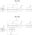
- Fig. 1(a) includes a power conversion apparatus 10, an emergency shutdown unit 30, a motor 40, and a load machine 50.
- the motor 40 is a device that converts electrical energy to mechanical energy and is a three-phase alternating current motor or the like, for example.
- the emergency shutdown unit 30 is a unit that outputs an emergency shutdown signal for putting the load machine 50 into a safe state.
- the emergency shutdown unit 30 is an emergency shutdown switch that outputs an emergency shutdown signal when pressed by an operator or the like who operates the load machine 50 or a light curtain or a safety door lock that detects approach of a person to the load machine 50 or opening of a no-entry door to output an emergency shutdown signal.
- the emergency shutdown unit 30 may be a safety relay, a safety PLC, or the like that is used by being connected to these apparatuses to output an emergency shutdown signal upon receiving a notification of emergency from the devices.
- the emergency shutdown signal is one of safety request signals for requesting execution of the safety function defined in the international standards IEC 61800-5-2.
- the power conversion apparatus 10 is an apparatus that controls the driving of the motor 40. The detailed configuration thereof will be described later.
- the power conversion apparatus 10 stops the motor 40 upon receiving an emergency shutdown signal from the emergency shutdown unit 30.
- Fig. 1 (b) is an example of a block diagram illustrating a functional configuration when operated by being connected to a safety function unit according to Embodiment 1.
- a safety function unit 20 operates by being connected to the power conversion apparatus 10 and outputs a control signal to the power conversion apparatus 10 so as to execute a safety function of decelerating and stopping the motor 40 or maintaining the speed at a predetermined speed as well as emergency shutdown of the motor 40.
- the detailed configuration thereof will be described later.
- the power conversion apparatus 10 can control the motor 40 and execute the safety function by itself and can execute a more advanced safety function when the safety function unit 20 is connected thereto.
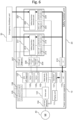
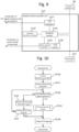
- Fig. 2 is an example of a diagram illustrating a configuration of the power conversion apparatus and the flow of data according to Embodiment 1.
- Fig. 2 the flow of signals in a normal state in which the motor 40 is driven according to an operation pattern stored in an operation management unit 101 is illustrated by arrows.
- the power conversion apparatus 10 includes the operation management unit 101, a main body control unit 102, a drive unit 103, a current detector 104, STO signal reception units 105 and 106, an STO self-diagnosis 107, option connection units 108 and 109, a communication unit 110, a display unit 111, and so forth.
- the operation management unit 101 outputs a speed instruction to the main body control unit 102 to control driving of the motor.
- the operation management unit 101 comprises a central processing unit (CPU) and a program running on the CPU.
- the operation management unit 101 outputs an instruction to notify the display unit 111 of the state of the power conversion apparatus 10 and outputs a communication instruction to the communication unit 110 when communicating with an external device.
- the main body control unit 102 outputs a pulse width modulation (PWM) control signal to the drive unit 103.
- PWM pulse width modulation
- the main body control unit 102 is a program running on the CPU.
- the drive unit 103 is a unit that supplies electric power for applying torque to the motor 40, and the detailed configuration thereof will be described with reference to Fig. 4 .
- the STO signal reception unit 105 is a terminal for receiving an emergency shutdown signal and transmits an emergency shutdown signal output from an emergency shutdown unit to the drive unit 103.
- the STO signal reception unit 106 is configured in a manner similar to the STO signal reception unit 105.
- the STO self-diagnosis unit 107 diagnoses whether a signal will be transferred from the STO signal reception unit 105 to the drive unit 103.
- the STO self-diagnosis unit 107 transmits test pulses at a predetermined time interval and detects whether a signal has arrived at the drive unit 103. When the signal has not been arrived, the STO self-diagnosis unit 107 notifies the operation management unit 101 of occurrence of an error.
- the operation management unit 101 transmits a target speed to the main body control unit 102 and the main body control unit 102 outputs a PWM control signal to the drive unit 103 according to the target speed.
- the drive unit 103 supplies a PWM-controlled voltage for generating torque to the motor 40 and the motor 40 is driven.
- the current detector 104 measures the current supplied to the motor 40 and outputs the measured current to the main body control unit 102.
- the main body control unit 102 performs PWM control using the current acquired from the current detector 104.
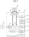
- Fig. 3 is an example of a diagram illustrating the flow of data when the power conversion apparatus stops emergently according to Embodiment 1. The flow of the process will be described with reference to Fig. 3 .
- the emergency shutdown unit 30 outputs an emergency shutdown signal to the STO signal reception unit. Subsequently, the STO signal reception unit having received the emergency shutdown signal outputs the emergency shutdown signal to the drive unit 103. Moreover, the drive unit 103 having received the emergency shutdown signal cuts off the PWM control signal with the aid of a gate drive unit 1035 illustrated in Fig. 4 .
- Fig. 4 is an example of a diagram illustrating a configuration of a drive unit included in the power conversion apparatus according to Embodiment 1. A mechanism of driving and emergency shutdown of the motor 40 will be described with reference to Fig. 4 .
- the drive unit 103 includes the gate drive unit 1035, a rectifier circuit unit 1032, a direct current smoothing circuit unit 1033, and an inverter unit 1034.
- the rectifier circuit unit 1032 is formed of a diode bridge, for example, and converts an alternating current voltage supplied from an external alternating current power source 60 to a direct current voltage.
- the direct current smoothing circuit unit 1033 is formed of a capacitor, for example, and smoothes the direct current voltage converted by the rectifier circuit unit 1032.
- the inverter unit 1034 is formed of six IGBTs (insulated gate bipolar transistors ), for example, and converts the direct current voltage smoothed by the direct current smoothing circuit unit 1033 to an alternating current voltage.
- IGBTs insulated gate bipolar transistors
- the main body control unit 102 outputs a PWM control signal to the gate drive unit 1035, and the gate drive unit 1035 outputs the received PWM control signal to the inverter unit 1034.
- the inverter unit 1034 generates an alternating current voltage which is PWM-controlled using the received PWM control signal and supplies the alternating current voltage to the motor 40. In this way, it is possible to control driving of the motor 40.
- the drive unit 103 stops supply of torque to the motor 40 to stop the motor 40.
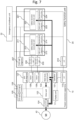
- Fig. 5 is an example of a diagram illustrating the configuration of the power conversion apparatus and the safety function unit and the flow of data during connection according to Embodiment 1.
- the safety function unit 20 includes a communication unit 210, control units 211 and 221, safety function execution units 212 and 222, MCU self-diagnosis units 213 and 223, deceleration instruction units 214 and 224, main body connection units 208 and 209, and an STO self-diagnosis unit 207.
- the communication unit 210 performs exchange of data between the safety function unit 20 and other information processing devices.
- the communication unit 210 is also used when exchanging information with the power conversion apparatus 10.
- the communication unit 210 performs a communication process or the like for allowing the safety function unit 20 to access the Internet, other information processing devices, and the like.
- it is not limited to a case in which only one communication unit 210 is used but a plurality of communication units may be provided to enable the use of a plurality of communication methods such as, for example Bluetooth, wireless LAN, code division multiple access (CDMA), and long term evolution (LTE: registered trademark).
- the communication unit 210 and the communication unit 110 may be duplexed. When the communication units are duplexed, even when one of communication units fails, since communication is performed using the other communication unit, the safety of the device is improved.
- the control unit 211 is comprises a CPU, for example, and performs a process such as management, calculation, and transmission and reception of data.
- the control unit 221 is configured in a manner similar to the control unit 211.
- the deceleration instruction unit 214 Upon receiving the emergency shutdown signal from the safety function execution unit 212, the deceleration instruction unit 214 outputs a deceleration instruction signal to the power conversion apparatus 10.
- the deceleration instruction unit 224 is configured in a manner similar to the deceleration instruction unit 214.
- Fig. 5 illustrates by arrows the flow of signals when the power conversion apparatus 10 and the safety function unit 20 are connected, and the flow of data during connection will be described with reference to this drawing.
- connection completion signals output from the option connection units 108 and 109 are transmitted to the operation management unit 101.
- connectiong completion signal is transmitted to the control unit 211 via the communication units 110 and 210.
- connection completion signals output from the main body connection units 208 and 209 are transmitted to the control unit 211.
- the connection completion signals are transmitted to the operation management unit 101 via the communication units 210 and 110. In this way, connection completion signals output from the power conversion apparatus 10 and the safety function unit 20 are exchanged and four connection completion signals in total are output.
- the terminal 130, the terminal of the option connection unit 108, and the terminal of the option connection unit 109 may be collectively configured as one coupler.
- Fig. 19(c) illustrates a circuit diagram illustrating a state in which the power conversion apparatus 10 and the safety function unit 20 are connected but the option connection unit 108 and the main body connection unit 208 are not connected due to a contact failure or the like.
- the voltages of the option connection unit 109 and the main body connection unit 209 increase (for example, 24 V) whereas the voltages of the option connection unit 108 and the main body connection unit 208 are low (for example, 0 V) . That is, a connection completion signal is output from the option connection unit 109 and the main body connection unit 209, and a disconnection signal is output from the option connection unit 108 and the main body connection unit 208.
- a connection switch button may be provided in the power conversion apparatus 10.
- the connection switch button is a button showing whether the safety function unit 20 is connected. For example, when a user connects the safety function unit 20, the user presses the connection switch button to explicitly notify the power conversion apparatus 10 of a fact that the safety function unit 20 is being connected. In this way, the power conversion apparatus 10 can acknowledge the connection state reliably and guarantee the safety.
- the power conversion apparatus 10 may store the connection state in the operation management unit 101 or the like. In this way, when the operation management unit 10 checks the connection state, it is possible to check the connection state using connection information stored in the operation management unit 101 in addition to the connecftion completion signal or the disconnection signal output from the option connection units 108 and 109. Therefore, it is possible to guarantee the safety more reliably.
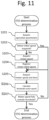
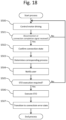
- step S301 when the option connection unit and the main body connection unit are connected (step S301: Yes), the option connection units 108 and 109 output connection completion signals (step S302), and the main body connection units 208 and 209 output connection completion signals (step S303).
- step S302 when the option connection unit or the main body connection unit operates normally, four connection completion signals are output.
- step S304 when one of the option connection unit and the main body connection unit fails, not four connection completion signals are output.
- step S304 when the option connection unit and the main body connection unit are not connected (step S301: No), the option connection units 108 and 109 output disconnection signals (step S304), and the main body coupling units 208 and 209 also output disconnection signals (step S305) .
- the operation management unit 101 receives the connection completion signal or the disconnection signal output from the option connection unit and the main body connection unit (step S306). Subsequently, confirmation is made on whether the timer has been activated (step S307) . When the timer is not activated (step S307: No), the timer is activated (step S308). This timer is used for measuring time when determining that a connection error has occurred if the operation management unit could not receive all connection completion signals within a predetermined period.
- connection completion signal is received (step S309: Connection completion signal)
- connection state transitions to a connecting state (step S311).
- the connecting state is one of the states held by the operation management unit 101 and is a state of waiting for a connection completion signal being output.
- the state is held as a variable (for example, state) defined in an execution program and the value 1 of the variable state shows the connecting state.
- the disconnection signal is received (step S309: Disconnection signal)
- the connecting state transitions to a non-connection state (step S310) .
- the non-connection state is a state showing that the safety function unit 20 is not connected to the power conversion apparatus 10. Unlike a connection error state, the power conversion apparatus 10 can start the operation of the motor in the non-connection state.
- step S312 confirmation is made on whether all connection completion signals have been received.
- step S312: Yes it is determined that connection has been performed normally and the connecting state transitions to a connection completion state (step S317). If all connection completion signals have not been received (step S312: No), confirmation is made on whether the timer has expired (step S313) . When the timer has not expired (step S313: No), the flow returns to step S306, and a process of receiving signals is executed.
- step S313 When the timer has expired in a state in which all connection completion signals could not be received (step S313: Yes), confirmation is made on whether the state is the connecting state (step S314) . If the state is the connecting state (step S314: Yes), it is determined that a connection error has occurred, and the connecting state transitions to a connection error state (step S315) . Moreover, if the stateis not the connecting state (step S314: No), the non-connection state is maintained (step S316).
- a content corresponding to the connection state is displayed on the display unit 111 (step S318).
- a message “Connection has been completed normally” or the like is displayed when the connection state is the connection completion state whereas a message “Connection error has occurred” is displayed when the connection state is the connection error state.
- the connection state may be displayed using LEDs or the like. Two different LEDs may be used: LEDs which are turned on when connection is completed normally and LEDs which are turned on when a connection error occurs. Or, the user may be notified by change in color of one LED that is turned on depending on the connection state. In this way, the user can immediately understand the connection state by seeing the LEDs and the safety is improved further.
- control unit 211 also receives the connection completion signal and executes the same process as the operation management unit 101, thereby acknowledging whether connection has been performed normally or an error has occurred.
- the STO signal reception units 105 and 106 may have the functions of the option connection units 108 and 109. In this way, it is possible to reduce the number of components and to reduce the component cost.
- the power conversion apparatus 10 and the safety function unit 20 are connected in a state both are turned off.
- the operation of the motor starts.
- the operation of the motor may start when connection is completed normally, and the motor is preferably not operated when a connection error occurs.
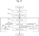
- connection process described in Fig. 16 is executed (step S402).
- the connection state transitions to any one of the connection completion state, the connection error state, the connecting state, and the non-connection state.
- a start button is pressed by the user (step S403).
- the operation management unit 101 checks the connection state (step S404).
- the connection state is the connection completion state or the non-connection state (step S404: "connection completion state or non-connection state")
- an operation start process of the motor is performed (step S406) .
- connection state is the connecting state (step S404: “connecting state”)
- the notice of the connenting state is displayed on the display unit 111 (step S405) and the state returns to a state of waiting for the pressing of the start button again.
- connection state is the connection error state (step S404: “connection error state”)
- connection error state the notice of the connection error state is displayed on the display unit 111 (step S407) and the state returns to a state of waiting for the pressing of the start button again.
- the operation management unit 101 outputs a speed instruction to the main body control unit 102 to control the driving of the motor (step S500).
- step S501 confirmation is made on whether a disconnection signal showing that connection is released or a connection completion signal showing that connection is completed is output from the option connection units 108 and 109 (step S501). If the signal is not output (step S501: No), motor driving control is performed again (step S500). If the signal is output (step S501: Yes), the connection state is acquired and checked (step S502). Moreover, the content of a process to be executed is determined according to a combination of the type of signal and the connection state (step S503).
- a disconnection signal is output in the connection completion state, it is determined that the safety function unit 20 is separated, a connection error has occurred, or malfunction has occurred, and it is necessary to put the motor into a safe state. Due to this, a notice to safely stop the motor is displayed and STO is executed so that the operation management unit instructs the main body control unit to stop the motor.
- connection completion signal when the connection completion signal is output in the non-connection state, it is determined that the safety function unit 20 is attached and a message that the safety function or the safety level is not improved although there is no influence on the operation of the motor even when the safety function unit 20 is attached during operation is displayed to notify the user of the same. In this case, STO may not be executed.
- connection completion signal is output in the connection completion state or the disconnection signal is output in the non-connection state
- this combination of events does not occur if the apparatus operates normally. Therefore, it is determined that there is a possibility that the option connection units 108 and 109 fail, a message is displayed to inform the user of the possibility of failure, and STO is executed.
- the content to be displayed on the display unit 111 and whether to execute STO are determined based on a combination of the type of the signal output by the option connection units 108 and 109 and the connection state.
- step S504 if there is a content to be notified to the user, the content is displayed on the display unit 111 (step S504).
- step S505: Yes STO is executed (step S506) and the coupling state transitions to the coupling error state (step S507) .
- step S505: No motor driving control is performed again (step S500).
- the signal is input to the safety function execution units 212 and 222 and is output to the deceleration instruction units 214 and 224 with an operation parameter to be described later appended thereto. Moreover, the emergency shutdown signal is transmitted to the operation management unit 101 via the communication units 210 and 110.
- the flow of a process in which the motor 40 is decelerated and the safety function execution unit monitors the speed of the motor 40 will be described with reference to Fig. 7 .
- the operation management 101 Upon receiving a deceleration instruction, the operation management 101 issues a deceleration instruction to the main body control unit 102 together with a parameter such as a deceleration. In response to this, the main body control unit 102 outputs a PWM control signal to the drive unit 103 to decelerate the motor 40.
- the main body control unit 102 acquires a current value for predicting a motor speed output from the current detector 104. Furthermore, the safety function execution units 212 and 222 also acquire the current value from the current detector 104. Using this value, the safety function execution units 212 and 222 start monitoring the speed of the motor 40. After that, when the speed of the motor 40 exceeds a predetermined threshold, the safety function execution units 212 and 222 output a safe torque-off signal to the drive unit 103 via 105 and 106.
- the safe torque-off signal is input to the drive unit 103 via the STO signal reception units 105 and 106. Moreover, the drive unit 103 turns off torque generated in the motor 40.
- the safety function execution unit 222 is configured in a manner similar to the safety function execution unit 212.
- the safety function execution unit 212 includes an STO execution unit 2121, an operation parameter storage unit 2122, an operation monitoring unit 2123, a motor speed predicting unit 2125, and a time monitoring unit 2126.
- the motor speed predicting unit 2125 predicts the speed of the motor 40 based on a current value or the like output by the current detector 104.
- the motor speed predicting unit 2125 calculates torque generated in the motor 40 from the magnitude or the frequency of a current supplied to the motor 40 and converts the torque to a rotation speed of the motor 40.
- An encoder that is attached to a motor to output a rotation speed of the motor may be used. In this way, it is possible to know a more accurate speed of the motor and to improve the safety function.
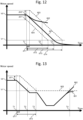
- Examples of the operation parameters stored in the operation parameter storage unit 2122 include the initial speed V0 of the motor, a speed V1 at which torque-off is executed, a lowest elapsed time dT2, a standard elapsed time dT3, and a largest elapsed time dT4 elapsed until torque-off is executed after an emergency shutdown signal is received, an increase dV2 and a decrease dV1 in the speed from the initial speed V0 of the motor, and a largest time dT1 elapsed until deceleration starts after the emergency shutdown signal is received.
- the operation parameters other than the initial speed V0 of the motor are set in advance from an external device.
- Fig. 15 is a diagram illustrating a display example of an operation unit and a display unit mounted on the power conversion apparatus according to Embodiment 1.
- the operation unit and the display unit are not necessarily mounted on the power conversion apparatus but may be detachably attached to the power conversion apparatus via a cable or the like.
- a notice of an error is displayed on the display portion 703. For example, an error number "No. 001" and a content such as an error content "Coupling error” are displayed.
- parameters showing the type of a safety function to be executed when the safety request signal is input are stored in the operation parameter storage unit 2122 of the safety function execution unit 212.
- a variable on a program are prepared, and the safety function execution unit 212 performs control such that SS1 is executed if the variable value is 1 and SLS is executed if the variable value is 2.
- the operation parameters of the respective safety functions are stored in the operation parameter storage unit 2122.
- a line 801 illustrates a change in the speed of the motor 40. Speed control is performed normally and the motor speed is controlled so as not to exceed the limit speed V1.
- the safety function execution unit 212 Upon receiving an SSM start signal, the safety function execution unit 212 receives the speed of the motor 40.
- the safety function execution unit 212 outputs a safe speed signal.
- the safe speed signal is transmitted to the operation management unit 101 via the communication units 210 and 110.
- the operation management unit 101 having received the safe speed signal displays a notice that the motor is operating at a safe speed on the display unit 111. For example, a message "Motor is operating within a safe speed range" is displayed.
- the safety function execution unit 212 outputs a safe speed excess signal.
- the safe speed excess signal is transmitted to the operation management unit 101 via the communication units 210 and 110.
- the operation management unit 101 having received the safe speed excess signal displays a notice that the motor speed exceeded the safe speed on the display unit 111. For example, a message "Motor speed exceeded safe speed" is displayed.
- the safety function unit 20 checks the value of a variable showing the type of a safety function to be executed, stored in the operation parameter storage unit 2122.
- this variable When the value of this variable is a value (for example, 99) showing that the type is not set, it is determined that the type is not set and a signal showing the parameter is not set is output to the display unit 111 of the power conversion apparatus 10.
- the display unit 111 having received this signal displays, for instance, a message "Operation parameter is not set" to notify the user of the fact.
Landscapes
- Engineering & Computer Science (AREA)
- Power Engineering (AREA)
- Inverter Devices (AREA)
- Control Of Ac Motors In General (AREA)
- Stopping Of Electric Motors (AREA)
- Control Of Electric Motors In General (AREA)
Claims (11)
- Appareil de conversion de puissance (10) comprenant :une unité pilote (103) incluant un onduleur (1034) configuré pour convertir un courant direct en un courant alternatif pour alimenter une puissance électrique à un moteur (40) et une unité pilote de grille (1035) configurée pour commander l'onduleur ; etune unité de connexion d'option (108, 109) configurée pour sortir un premier signal d'achèvement de connexion indiquant si une unité à fonction de sécurité (20) est connectée à l'appareil de conversion de puissance (10), l'unité à fonction de sécurité (20) incluant une unité de connexion de corps principal (208, 209) configurée pour sortir un second signal d'achèvement de connexion indiquant si l'unité à fonction de sécurité (20) est connectée et pour recevoir le premier signal d'achèvement de connexion indiquant si l'appareil de conversion de puissance (10) est connecté,caractérisé en ce que :
le premier signal d'achèvement de connexion est reçu par une unité de commande (211) de l'unité à fonction de sécurité (20) et le second signal d'achèvement de connexion est reçu par une unité de gestion de fonctionnement (101) de l'appareil de conversion de puissance (10), dans lequel, quand une réception du premier signal d'achèvement de connexion ou du second signal d'achèvement de connexion échoue, l'unité pilote de grille (1035) reçoit un signal d'interruption d'urgence transmis par une unité d'interruption d'urgence (30) de telle sorte que l'unité pilote de grille (1035) commande l'onduleur de telle sorte qu'il n'alimente pas une tension afin de décélérer le moteur (40). - Appareil de conversion de puissance (10) selon la revendication 1, comprenant en outre :- une unité de commande de corps principal (102) configurée pour transmettre à l'unité pilote de grille (1035) un signal destiné à commander l'onduleur (1034) ; et- une première unité de communication (110) configurée pour recevoir, depuis l'unité à fonction de sécurité (20), un signal de commande de vitesse destiné à commander l'unité pilote (103), dans lequelquand le premier signal d'achèvement de connexion, sorti par l'unité de connexion d'option (108, 109), indique que l'unité à fonction de sécurité (20) est connectée à l'appareil de conversion de puissance (10), la première unité de communication (110) reçoit le signal de commande de vitesse indiquant une vitesse de moteur depuis l'unité à fonction de sécurité (20) et transmet le signal de commande de vitesse à l'unité de commande de corps principal (102), et l'unité de commande de corps principal (102) indique à l'unité pilote de grille (1035) de sortir le signal de commande d'onduleur (1034) pour alimenter une tension destinée à décélérer le moteur (40) vers l'onduleur (1034), sur la base du signal de commande de vitesse.
- Appareil de conversion de puissance (10) selon la revendication 2, comprenant en outre :- un détecteur de courant (104) configuré pour détecter un courant s'écoulant à travers l'onduleur (1034), dans lequelquand le premier signal d'achèvement de connexion, sorti par l'unité de connexion d'option (108, 109), indique que l'unité à fonction de sécurité (20) est connectée à l'appareil de conversion de puissance (10), une valeur du courant s'écoulant à travers l'onduleur (1034), qui est détecté par le détecteur de courant (104), est transmise à l'unité à fonction de sécurité (20), etl'unité pilote de grille (1035) reçoit un signal d'arrêt de couple de sécurité sorti par l'unité à fonction de sécurité (20), sur la base de la valeur transmise du courant, et commande l'onduleur (1034) de sorte qu'il n'alimente pas la tension pour piloter le moteur (40).
- Appareil de conversion de puissance (10) selon la revendication 3, dans lequel l'unité de gestion de fonctionnement (101) est en outre configurée pour recevoir des informations, qui indiquent si le moteur (40) est en fonctionnement, depuis l'unité de commande de corps principal (102), et pour recevoir le premier signal d'achèvement de connexion, qui indique si l'unité à fonction de sécurité (20) est connectée à l'appareil de conversion de puissance (10), depuis l'unité de connexion d'option (108, 109), est configurée pour sortir des informations, qui indiquent que la connexion de l'unité à fonction de sécurité (20) avec l'appareil de conversion de puissance (10) est déconnectée, vers une unité d'affichage (111), quand le premier signal d'achèvement de connexion, qui indique que l'unité à fonction de sécurité (20) est connectée, est perdu pendant un fonctionnement du moteur (40), et pour donner instruction à l'unité de commande de corps principal (102) d'arrêter le moteur (40).
- Appareil de conversion de puissance (10) selon la revendication 3, dans lequel
des informations indiquant si le moteur (40) est en fonctionnement sont reçues depuis l'unité de commande de corps principal (102), et le second signal d'achèvement de connexion indiquant si l'unité à fonction de sécurité (20) est connectée à l'appareil de conversion de puissance (10), est reçu depuis l'unité de connexion d'option (108, 109), et quand un signal indiquant que l'unité à fonction de sécurité (20) est couplée pendant un fonctionnement du moteur (40) est reçu, des informations indiquant que l'unité à fonction de sécurité (20) est connectée pendant un fonctionnement du moteur (40) sont sorties vers une unité d'affichage (111). - Système de conversion de puissance incluant un appareil de conversion de puissance (10) selon la revendication 1 et une unité à fonction de sécurité (20), dans lequel
l'unité à fonction de sécurité (20) inclut :- une unité d'exécution à fonction de sécurité (212, 222) configurée pour recevoir une valeur du courant de l'onduleur (1034) depuis le détecteur de courant (104) et pour générer des informations destinées à commander le moteur (40), sur la base de la valeur reçue du courant ; et- une seconde unité de communication (210) configurée pour transmettre les informations destinées à commander le moteur (40), générées par l'unité d'exécution à fonction de sécurité (212, 222), à l'appareil de conversion de puissance (10). - Procédé de conversion de puissance comprenant les étapes consistant à :- permettre à une unité pilote de grille (1035) de commander un onduleur (1034) pour qu'il convertisse un courant direct en un courant alternatif et pour qu'il alimente une puissance électrique à un moteur (40) ;- recevoir un premier signal d'achèvement de connexion depuis une unité de connexion d'option (108, 109), le premier signal d'achèvement de connexion indiquant si l'unité de connexion d'option (108, 109) est connectée à une unité à fonction de sécurité (20) ;- sortir, via une unité de connexion de corps principal (208, 209), un second signal d'achèvement de connexion, le second signal d'achèvement de connexion indiquant si l'unité à fonction de sécurité (20) est connectée, et- recevoir le premier signal d'achèvement de connexion indiquant si l'appareil de conversion de puissance (10) est connecté,caractérisé par les étapes consistant à :- recevoir, via une unité de commande (211) de l'unité à fonction de sécurité (20), le premier signal d'achèvement de connexion, et- recevoir, via une unité de gestion de fonctionnement (101) l'appareil de conversion de puissance (10), le second signal d'achèvement de connexion, et quand une réception du premier signal d'achèvement de connexion ou du second signal d'achèvement de connexion échoue, l'unité pilote de grille (1035) reçoit un signal d'interruption d'urgence transmis par une unité d'interruption d'urgence (30) pour- permettre à l'unité pilote de grille (1035) de commander l'onduleur (1034) pour qu'il n'alimente pas une tension afin de décélérer le moteur (40).
- Procédé de conversion de puissance selon la revendication 7, comprenant en outre les étapes consistant à :permettre à une première unité de communication (110) de recevoir un signal de commande de vitesse indiquant une vitesse du moteur (40) depuis l'unité à fonction de sécurité (20) quand le premier signal d'achèvement de connexion de l'unité de connexion d'option (108, 109) indique que l'unité à fonction de sécurité (20) est connectée à l'unité de connexion d'option (108, 109) ;transmettre le signal de commande de vitesse à une unité de commande de corps principal (102) ; etpermettre à l'unité de commande de corps principal (102) de donner instruction à l'unité pilote de grille (1035) de sortir vers l'onduleur (1034) un signal destiné à alimenter une tension pour décélérer le moteur (40), sur la base du signal de commande de vitesse.
- Procédé de conversion de puissance selon la revendication 8, comprenant en outre les étapes consistant à :transmettre une valeur d'un courant s'écoulant à travers l'onduleur (1034), détecté par le détecteur de courant (104), à l'unité à fonction de sécurité (20) quand le premier signal d'achèvement de connexion de l'unité de connexion d'option (108, 109) indique que l'unité à fonction de sécurité (20) est connectée à l'unité de connexion d'option (108, 109) ;permettre à l'unité pilote de grille (1035) de recevoir un signal d'arrêt de couple de sécurité sorti par l'unité à fonction de sécurité (20), sur la base de la valeur transmise du courant ; etpermettre à l'unité pilote de grille (1035) de commander l'onduleur (1034) de sorte qu'il n'alimente pas une tension pour piloter le moteur (40).
- Procédé de conversion de puissance selon la revendication 9, comprenant en outre les étapes consistant à :permettre à une unité de gestion de fonctionnement (101) de recevoir des informations, qui indiquent si le moteur (40) est en fonctionnement, depuis l'unité de commande de corps principal (102), et de recevoir le premier signal d'achèvement de connexion, qui indique si l'unité à fonction de sécurité (20) est connectée à l'unité de connexion d'option (108, 109), depuis l'unité de connexion d'option (108, 109) ; etsortir vers l'unité d'affichage (111) des informations, qui indiquent que la connexion de l'unité de connexion d'option (108, 109) avec l'unité à fonction de sécurité (20) est déconnectée quand le premier signal d'achèvement de connexion, qui indique que l'unité à fonction de sécurité (20) est connectée, est perdu pendant un fonctionnement du moteur (40), et donner instruction à l'unité de commande de corps principal (102) d'arrêter le moteur (40).
- Procédé de conversion de puissance selon la revendication 9, comprenant en outre les étapes consistant à :permettre à l'unité de gestion de fonctionnement (101) de recevoir des informations indiquant si le moteur (40) est en fonctionnement depuis l'unité de commande de corps principal (102) et le premier signal d'achèvement de connexion indiquant si l'unité à fonction de sécurité (20) est connectée à l'unité de connexion d'option (108, 109) ; etsortir vers une unité d'affichage (111) des informations indiquant que l'unité à fonction de sécurité (20) est connectée à l'unité de connexion d'option (108, 109) pendant un fonctionnement du moteur (40) quand un second signal d'achèvement de connexion, indiquant que l'unité à fonction de sécurité (20) est couplée pendant un fonctionnement du moteur (40) est reçu.
Applications Claiming Priority (1)
| Application Number | Priority Date | Filing Date | Title |
|---|---|---|---|
| PCT/JP2014/076238 WO2016051552A1 (fr) | 2014-10-01 | 2014-10-01 | Dispositif de conversion d'énergie, procédé de conversion d'énergie et système de conversion d'énergie |
Publications (3)
| Publication Number | Publication Date |
|---|---|
| EP3203627A1 EP3203627A1 (fr) | 2017-08-09 |
| EP3203627A4 EP3203627A4 (fr) | 2018-05-16 |
| EP3203627B1 true EP3203627B1 (fr) | 2023-12-20 |
Family
ID=55629643
Family Applications (1)
| Application Number | Title | Priority Date | Filing Date |
|---|---|---|---|
| EP14902952.2A Active EP3203627B1 (fr) | 2014-10-01 | 2014-10-01 | Dispositif de conversion d'énergie, procédé de conversion d'énergie et système de conversion d'énergie |
Country Status (4)
| Country | Link |
|---|---|
| EP (1) | EP3203627B1 (fr) |
| JP (1) | JP6313463B2 (fr) |
| CN (1) | CN106664043B (fr) |
| WO (1) | WO2016051552A1 (fr) |
Families Citing this family (16)
| Publication number | Priority date | Publication date | Assignee | Title |
|---|---|---|---|---|
| JP6772887B2 (ja) * | 2017-02-21 | 2020-10-21 | オムロン株式会社 | サーボシステム |
| JP6825412B2 (ja) * | 2017-02-21 | 2021-02-03 | オムロン株式会社 | モータ制御装置 |
| JP6369590B1 (ja) * | 2017-04-11 | 2018-08-08 | 株式会社安川電機 | モータ制御システム、モータ制御装置、及び安全機能設定方法 |
| EP3633465B1 (fr) * | 2017-05-31 | 2022-05-04 | Panasonic Intellectual Property Management Co., Ltd. | Appareil de diagnostic |
| GB2566497B (en) * | 2017-09-15 | 2020-07-29 | Illinois Tool Works | Braking system for electromagnetic motors |
| JP6814119B2 (ja) * | 2017-09-19 | 2021-01-13 | 株式会社日立産機システム | 電力変換装置および安全機能モジュール |
| EP3460593B1 (fr) * | 2017-09-22 | 2021-06-30 | B&R Industrial Automation GmbH | Dispositif de commutation sécurisé |
| CN109586618B (zh) * | 2017-09-29 | 2022-10-04 | 施耐德电气工业公司 | 一种用于电气设备的驱动系统 |
| JP7112240B2 (ja) * | 2018-04-25 | 2022-08-03 | 株式会社日立産機システム | 電力変換システム及び電力変換方法 |
| TWI681620B (zh) | 2018-05-18 | 2020-01-01 | 茂達電子股份有限公司 | 馬達驅動電路 |
| US11362614B2 (en) | 2019-03-18 | 2022-06-14 | Mitsubishi Electric Corporation | Power conversion apparatus, drive control system, machine learning apparatus, and motor monitoring method |
| WO2020188693A1 (fr) | 2019-03-18 | 2020-09-24 | 三菱電機株式会社 | Convertisseur de puissance et procédé de surveillance de moteur |
| CN112117952B (zh) * | 2019-06-20 | 2022-04-19 | 台达电子工业股份有限公司 | 马达驱动系统及控制方法 |
| DE102021208168A1 (de) * | 2021-07-29 | 2023-02-02 | Robert Bosch Gesellschaft mit beschränkter Haftung | Steuervorrichtung für ein Antriebssystem, Antriebssystem, Verfahren |
| JP7697060B2 (ja) * | 2022-01-26 | 2025-06-23 | 株式会社日立産機システム | 制御装置および加工機器 |
| WO2025203382A1 (fr) * | 2024-03-27 | 2025-10-02 | ファナック株式会社 | Dispositif de servocommande et procédé de servocommande |
Family Cites Families (10)
| Publication number | Priority date | Publication date | Assignee | Title |
|---|---|---|---|---|
| JPH05316743A (ja) * | 1992-05-07 | 1993-11-26 | Toyota Motor Corp | インバータ駆動制御装置 |
| JPH09215388A (ja) * | 1996-01-29 | 1997-08-15 | Toyota Motor Corp | インバータ装置 |
| JP3476770B2 (ja) * | 2000-12-18 | 2003-12-10 | 科学技術振興事業団 | 電気自動車の制御装置 |
| JP2004062652A (ja) * | 2002-07-30 | 2004-02-26 | Mitsubishi Cable Ind Ltd | ロール機械用安全装置 |
| JP2008178236A (ja) * | 2007-01-19 | 2008-07-31 | Yaskawa Electric Corp | インバータ装置とそのプログラミング装置 |
| DE102008014495B4 (de) * | 2008-03-15 | 2023-04-27 | Iav Gmbh Ingenieurgesellschaft Auto Und Verkehr | Verfahren und Vorrichtung zur Steuerung eines Antriebsstrangs eines Fahrzeugs |
| JP5412993B2 (ja) * | 2009-06-26 | 2014-02-12 | 富士電機株式会社 | 安全装置および電力変換器 |
| JP5367623B2 (ja) * | 2010-03-15 | 2013-12-11 | オムロン株式会社 | サーボシステム、サーボモータ駆動装置、セーフティユニットおよびサーボシステムの制御方法 |
| JP4817084B2 (ja) * | 2010-03-30 | 2011-11-16 | 株式会社安川電機 | モータ駆動システム及びモータ制御装置 |
| JP5830952B2 (ja) * | 2011-06-16 | 2015-12-09 | 富士電機株式会社 | インバータ装置 |
-
2014
- 2014-10-01 JP JP2016551423A patent/JP6313463B2/ja active Active
- 2014-10-01 EP EP14902952.2A patent/EP3203627B1/fr active Active
- 2014-10-01 WO PCT/JP2014/076238 patent/WO2016051552A1/fr not_active Ceased
- 2014-10-01 CN CN201480081545.8A patent/CN106664043B/zh active Active
Also Published As
| Publication number | Publication date |
|---|---|
| CN106664043B (zh) | 2019-08-20 |
| JP6313463B2 (ja) | 2018-04-18 |
| EP3203627A1 (fr) | 2017-08-09 |
| WO2016051552A1 (fr) | 2016-04-07 |
| CN106664043A (zh) | 2017-05-10 |
| JPWO2016051552A1 (ja) | 2017-04-27 |
| EP3203627A4 (fr) | 2018-05-16 |
Similar Documents
| Publication | Publication Date | Title |
|---|---|---|
| EP3203627B1 (fr) | Dispositif de conversion d'énergie, procédé de conversion d'énergie et système de conversion d'énergie | |
| CN107204608B (zh) | 马达控制装置 | |
| US8502489B2 (en) | Motor control device | |
| JP5260718B2 (ja) | 産業用ロボットの可動部の回転軸に接続されたサーボモータを駆動するサーボモータ駆動装置 | |
| TWI577514B (zh) | Robot control system | |
| US11442415B2 (en) | Power conversion system and power conversion method | |
| JP2017200421A (ja) | 電力変換装置の動作制御装置 | |
| EP3101791B1 (fr) | Dispositif d'alimentation de commande pour onduleur | |
| JP2016206842A (ja) | 制御装置 | |
| CN112335173B (zh) | 切断电路诊断装置 | |
| US8575884B2 (en) | Motor drive control system enabling connection of direct current/alternating current conversion device | |
| KR101272464B1 (ko) | 무대장치 제어시스템 | |
| KR101292683B1 (ko) | 제어 장치 및 제어 방법 | |
| CN109951096B (zh) | 电力转换装置 | |
| JP5129363B2 (ja) | モータ制御装置 | |
| JP5214380B2 (ja) | クレーンのマトリックスコンバータの制御方法 | |
| JP2017135933A (ja) | 多軸モータ駆動装置、多軸モータ駆動装置の診断方法、ベースモジュール及びアンプモジュール | |
| KR100734345B1 (ko) | 모터 제어 시스템 | |
| CN113716419A (zh) | 救援设备和电梯 | |
| CN101397110A (zh) | 电梯的通信系统 | |
| JP2011176898A (ja) | モータ制御装置 | |
| CN109502485A (zh) | 吊具驱动控制装置及电动吊具 |
Legal Events
| Date | Code | Title | Description |
|---|---|---|---|
| STAA | Information on the status of an ep patent application or granted ep patent |
Free format text: STATUS: THE INTERNATIONAL PUBLICATION HAS BEEN MADE |
|
| PUAI | Public reference made under article 153(3) epc to a published international application that has entered the european phase |
Free format text: ORIGINAL CODE: 0009012 |
|
| STAA | Information on the status of an ep patent application or granted ep patent |
Free format text: STATUS: REQUEST FOR EXAMINATION WAS MADE |
|
| 17P | Request for examination filed |
Effective date: 20170502 |
|
| AK | Designated contracting states |
Kind code of ref document: A1 Designated state(s): AL AT BE BG CH CY CZ DE DK EE ES FI FR GB GR HR HU IE IS IT LI LT LU LV MC MK MT NL NO PL PT RO RS SE SI SK SM TR |
|
| AX | Request for extension of the european patent |
Extension state: BA ME |
|
| DAX | Request for extension of the european patent (deleted) | ||
| A4 | Supplementary search report drawn up and despatched |
Effective date: 20180418 |
|
| RIC1 | Information provided on ipc code assigned before grant |
Ipc: H02P 3/18 20060101AFI20180412BHEP Ipc: H02P 29/024 20160101ALI20180412BHEP Ipc: G05B 9/03 20060101ALI20180412BHEP |
|
| STAA | Information on the status of an ep patent application or granted ep patent |
Free format text: STATUS: EXAMINATION IS IN PROGRESS |
|
| 17Q | First examination report despatched |
Effective date: 20200526 |
|
| GRAP | Despatch of communication of intention to grant a patent |
Free format text: ORIGINAL CODE: EPIDOSNIGR1 |
|
| STAA | Information on the status of an ep patent application or granted ep patent |
Free format text: STATUS: GRANT OF PATENT IS INTENDED |
|
| INTG | Intention to grant announced |
Effective date: 20230704 |
|
| GRAS | Grant fee paid |
Free format text: ORIGINAL CODE: EPIDOSNIGR3 |
|
| GRAA | (expected) grant |
Free format text: ORIGINAL CODE: 0009210 |
|
| STAA | Information on the status of an ep patent application or granted ep patent |
Free format text: STATUS: THE PATENT HAS BEEN GRANTED |
|
| AK | Designated contracting states |
Kind code of ref document: B1 Designated state(s): AL AT BE BG CH CY CZ DE DK EE ES FI FR GB GR HR HU IE IS IT LI LT LU LV MC MK MT NL NO PL PT RO RS SE SI SK SM TR |
|
| REG | Reference to a national code |
Ref country code: GB Ref legal event code: FG4D |
|
| P01 | Opt-out of the competence of the unified patent court (upc) registered |
Effective date: 20231120 |
|
| REG | Reference to a national code |
Ref country code: DE Ref legal event code: R096 Ref document number: 602014089165 Country of ref document: DE |
|
| REG | Reference to a national code |
Ref country code: CH Ref legal event code: EP |
|
| REG | Reference to a national code |
Ref country code: IE Ref legal event code: FG4D |
|
| PG25 | Lapsed in a contracting state [announced via postgrant information from national office to epo] |
Ref country code: GR Free format text: LAPSE BECAUSE OF FAILURE TO SUBMIT A TRANSLATION OF THE DESCRIPTION OR TO PAY THE FEE WITHIN THE PRESCRIBED TIME-LIMIT Effective date: 20240321 |
|
| REG | Reference to a national code |
Ref country code: LT Ref legal event code: MG9D |
|
| PG25 | Lapsed in a contracting state [announced via postgrant information from national office to epo] |
Ref country code: LT Free format text: LAPSE BECAUSE OF FAILURE TO SUBMIT A TRANSLATION OF THE DESCRIPTION OR TO PAY THE FEE WITHIN THE PRESCRIBED TIME-LIMIT Effective date: 20231220 |
|
| REG | Reference to a national code |
Ref country code: NL Ref legal event code: MP Effective date: 20231220 |
|
| PG25 | Lapsed in a contracting state [announced via postgrant information from national office to epo] |
Ref country code: ES Free format text: LAPSE BECAUSE OF FAILURE TO SUBMIT A TRANSLATION OF THE DESCRIPTION OR TO PAY THE FEE WITHIN THE PRESCRIBED TIME-LIMIT Effective date: 20231220 |
|
| PG25 | Lapsed in a contracting state [announced via postgrant information from national office to epo] |
Ref country code: LT Free format text: LAPSE BECAUSE OF FAILURE TO SUBMIT A TRANSLATION OF THE DESCRIPTION OR TO PAY THE FEE WITHIN THE PRESCRIBED TIME-LIMIT Effective date: 20231220 Ref country code: GR Free format text: LAPSE BECAUSE OF FAILURE TO SUBMIT A TRANSLATION OF THE DESCRIPTION OR TO PAY THE FEE WITHIN THE PRESCRIBED TIME-LIMIT Effective date: 20240321 Ref country code: FI Free format text: LAPSE BECAUSE OF FAILURE TO SUBMIT A TRANSLATION OF THE DESCRIPTION OR TO PAY THE FEE WITHIN THE PRESCRIBED TIME-LIMIT Effective date: 20231220 Ref country code: ES Free format text: LAPSE BECAUSE OF FAILURE TO SUBMIT A TRANSLATION OF THE DESCRIPTION OR TO PAY THE FEE WITHIN THE PRESCRIBED TIME-LIMIT Effective date: 20231220 Ref country code: BG Free format text: LAPSE BECAUSE OF FAILURE TO SUBMIT A TRANSLATION OF THE DESCRIPTION OR TO PAY THE FEE WITHIN THE PRESCRIBED TIME-LIMIT Effective date: 20240320 |
|
| REG | Reference to a national code |
Ref country code: AT Ref legal event code: MK05 Ref document number: 1643328 Country of ref document: AT Kind code of ref document: T Effective date: 20231220 |
|
| PG25 | Lapsed in a contracting state [announced via postgrant information from national office to epo] |
Ref country code: NL Free format text: LAPSE BECAUSE OF FAILURE TO SUBMIT A TRANSLATION OF THE DESCRIPTION OR TO PAY THE FEE WITHIN THE PRESCRIBED TIME-LIMIT Effective date: 20231220 |
|
| PG25 | Lapsed in a contracting state [announced via postgrant information from national office to epo] |
Ref country code: SE Free format text: LAPSE BECAUSE OF FAILURE TO SUBMIT A TRANSLATION OF THE DESCRIPTION OR TO PAY THE FEE WITHIN THE PRESCRIBED TIME-LIMIT Effective date: 20231220 Ref country code: RS Free format text: LAPSE BECAUSE OF FAILURE TO SUBMIT A TRANSLATION OF THE DESCRIPTION OR TO PAY THE FEE WITHIN THE PRESCRIBED TIME-LIMIT Effective date: 20231220 Ref country code: NO Free format text: LAPSE BECAUSE OF FAILURE TO SUBMIT A TRANSLATION OF THE DESCRIPTION OR TO PAY THE FEE WITHIN THE PRESCRIBED TIME-LIMIT Effective date: 20240320 Ref country code: NL Free format text: LAPSE BECAUSE OF FAILURE TO SUBMIT A TRANSLATION OF THE DESCRIPTION OR TO PAY THE FEE WITHIN THE PRESCRIBED TIME-LIMIT Effective date: 20231220 Ref country code: LV Free format text: LAPSE BECAUSE OF FAILURE TO SUBMIT A TRANSLATION OF THE DESCRIPTION OR TO PAY THE FEE WITHIN THE PRESCRIBED TIME-LIMIT Effective date: 20231220 Ref country code: HR Free format text: LAPSE BECAUSE OF FAILURE TO SUBMIT A TRANSLATION OF THE DESCRIPTION OR TO PAY THE FEE WITHIN THE PRESCRIBED TIME-LIMIT Effective date: 20231220 |
|
| PG25 | Lapsed in a contracting state [announced via postgrant information from national office to epo] |
Ref country code: IS Free format text: LAPSE BECAUSE OF FAILURE TO SUBMIT A TRANSLATION OF THE DESCRIPTION OR TO PAY THE FEE WITHIN THE PRESCRIBED TIME-LIMIT Effective date: 20240420 |
|
| PG25 | Lapsed in a contracting state [announced via postgrant information from national office to epo] |
Ref country code: AT Free format text: LAPSE BECAUSE OF FAILURE TO SUBMIT A TRANSLATION OF THE DESCRIPTION OR TO PAY THE FEE WITHIN THE PRESCRIBED TIME-LIMIT Effective date: 20231220 Ref country code: CZ Free format text: LAPSE BECAUSE OF FAILURE TO SUBMIT A TRANSLATION OF THE DESCRIPTION OR TO PAY THE FEE WITHIN THE PRESCRIBED TIME-LIMIT Effective date: 20231220 |
|
| PG25 | Lapsed in a contracting state [announced via postgrant information from national office to epo] |
Ref country code: SK Free format text: LAPSE BECAUSE OF FAILURE TO SUBMIT A TRANSLATION OF THE DESCRIPTION OR TO PAY THE FEE WITHIN THE PRESCRIBED TIME-LIMIT Effective date: 20231220 |
|
| PG25 | Lapsed in a contracting state [announced via postgrant information from national office to epo] |
Ref country code: SM Free format text: LAPSE BECAUSE OF FAILURE TO SUBMIT A TRANSLATION OF THE DESCRIPTION OR TO PAY THE FEE WITHIN THE PRESCRIBED TIME-LIMIT Effective date: 20231220 Ref country code: SK Free format text: LAPSE BECAUSE OF FAILURE TO SUBMIT A TRANSLATION OF THE DESCRIPTION OR TO PAY THE FEE WITHIN THE PRESCRIBED TIME-LIMIT Effective date: 20231220 Ref country code: RO Free format text: LAPSE BECAUSE OF FAILURE TO SUBMIT A TRANSLATION OF THE DESCRIPTION OR TO PAY THE FEE WITHIN THE PRESCRIBED TIME-LIMIT Effective date: 20231220 Ref country code: IS Free format text: LAPSE BECAUSE OF FAILURE TO SUBMIT A TRANSLATION OF THE DESCRIPTION OR TO PAY THE FEE WITHIN THE PRESCRIBED TIME-LIMIT Effective date: 20240420 Ref country code: EE Free format text: LAPSE BECAUSE OF FAILURE TO SUBMIT A TRANSLATION OF THE DESCRIPTION OR TO PAY THE FEE WITHIN THE PRESCRIBED TIME-LIMIT Effective date: 20231220 Ref country code: CZ Free format text: LAPSE BECAUSE OF FAILURE TO SUBMIT A TRANSLATION OF THE DESCRIPTION OR TO PAY THE FEE WITHIN THE PRESCRIBED TIME-LIMIT Effective date: 20231220 Ref country code: AT Free format text: LAPSE BECAUSE OF FAILURE TO SUBMIT A TRANSLATION OF THE DESCRIPTION OR TO PAY THE FEE WITHIN THE PRESCRIBED TIME-LIMIT Effective date: 20231220 |
|
| PG25 | Lapsed in a contracting state [announced via postgrant information from national office to epo] |
Ref country code: PL Free format text: LAPSE BECAUSE OF FAILURE TO SUBMIT A TRANSLATION OF THE DESCRIPTION OR TO PAY THE FEE WITHIN THE PRESCRIBED TIME-LIMIT Effective date: 20231220 Ref country code: PT Free format text: LAPSE BECAUSE OF FAILURE TO SUBMIT A TRANSLATION OF THE DESCRIPTION OR TO PAY THE FEE WITHIN THE PRESCRIBED TIME-LIMIT Effective date: 20240422 |
|
| PG25 | Lapsed in a contracting state [announced via postgrant information from national office to epo] |
Ref country code: PT Free format text: LAPSE BECAUSE OF FAILURE TO SUBMIT A TRANSLATION OF THE DESCRIPTION OR TO PAY THE FEE WITHIN THE PRESCRIBED TIME-LIMIT Effective date: 20240422 Ref country code: PL Free format text: LAPSE BECAUSE OF FAILURE TO SUBMIT A TRANSLATION OF THE DESCRIPTION OR TO PAY THE FEE WITHIN THE PRESCRIBED TIME-LIMIT Effective date: 20231220 |
|
| REG | Reference to a national code |
Ref country code: DE Ref legal event code: R097 Ref document number: 602014089165 Country of ref document: DE |
|
| PG25 | Lapsed in a contracting state [announced via postgrant information from national office to epo] |
Ref country code: DK Free format text: LAPSE BECAUSE OF FAILURE TO SUBMIT A TRANSLATION OF THE DESCRIPTION OR TO PAY THE FEE WITHIN THE PRESCRIBED TIME-LIMIT Effective date: 20231220 |
|
| PLBE | No opposition filed within time limit |
Free format text: ORIGINAL CODE: 0009261 |
|
| STAA | Information on the status of an ep patent application or granted ep patent |
Free format text: STATUS: NO OPPOSITION FILED WITHIN TIME LIMIT |
|
| PG25 | Lapsed in a contracting state [announced via postgrant information from national office to epo] |
Ref country code: SI Free format text: LAPSE BECAUSE OF FAILURE TO SUBMIT A TRANSLATION OF THE DESCRIPTION OR TO PAY THE FEE WITHIN THE PRESCRIBED TIME-LIMIT Effective date: 20231220 |
|
| PG25 | Lapsed in a contracting state [announced via postgrant information from national office to epo] |
Ref country code: SI Free format text: LAPSE BECAUSE OF FAILURE TO SUBMIT A TRANSLATION OF THE DESCRIPTION OR TO PAY THE FEE WITHIN THE PRESCRIBED TIME-LIMIT Effective date: 20231220 Ref country code: DK Free format text: LAPSE BECAUSE OF FAILURE TO SUBMIT A TRANSLATION OF THE DESCRIPTION OR TO PAY THE FEE WITHIN THE PRESCRIBED TIME-LIMIT Effective date: 20231220 |
|
| 26N | No opposition filed |
Effective date: 20240923 |
|
| REG | Reference to a national code |
Ref country code: CH Ref legal event code: PL |
|
| GBPC | Gb: european patent ceased through non-payment of renewal fee |
Effective date: 20241001 |
|
| PG25 | Lapsed in a contracting state [announced via postgrant information from national office to epo] |
Ref country code: MC Free format text: LAPSE BECAUSE OF FAILURE TO SUBMIT A TRANSLATION OF THE DESCRIPTION OR TO PAY THE FEE WITHIN THE PRESCRIBED TIME-LIMIT Effective date: 20231220 |
|
| PG25 | Lapsed in a contracting state [announced via postgrant information from national office to epo] |
Ref country code: GB Free format text: LAPSE BECAUSE OF NON-PAYMENT OF DUE FEES Effective date: 20241001 |
|
| PG25 | Lapsed in a contracting state [announced via postgrant information from national office to epo] |
Ref country code: BE Free format text: LAPSE BECAUSE OF NON-PAYMENT OF DUE FEES Effective date: 20241031 Ref country code: LU Free format text: LAPSE BECAUSE OF NON-PAYMENT OF DUE FEES Effective date: 20241001 |
|
| PG25 | Lapsed in a contracting state [announced via postgrant information from national office to epo] |
Ref country code: CH Free format text: LAPSE BECAUSE OF NON-PAYMENT OF DUE FEES Effective date: 20241031 |
|
| REG | Reference to a national code |
Ref country code: BE Ref legal event code: MM Effective date: 20241031 |
|
| PGFP | Annual fee paid to national office [announced via postgrant information from national office to epo] |
Ref country code: IT Payment date: 20250923 Year of fee payment: 12 |
|
| PGFP | Annual fee paid to national office [announced via postgrant information from national office to epo] |
Ref country code: FR Payment date: 20250924 Year of fee payment: 12 |
|
| PG25 | Lapsed in a contracting state [announced via postgrant information from national office to epo] |
Ref country code: IE Free format text: LAPSE BECAUSE OF NON-PAYMENT OF DUE FEES Effective date: 20241001 |
|
| PGFP | Annual fee paid to national office [announced via postgrant information from national office to epo] |
Ref country code: DE Payment date: 20250923 Year of fee payment: 12 |
|
| PG25 | Lapsed in a contracting state [announced via postgrant information from national office to epo] |
Ref country code: CY Free format text: LAPSE BECAUSE OF FAILURE TO SUBMIT A TRANSLATION OF THE DESCRIPTION OR TO PAY THE FEE WITHIN THE PRESCRIBED TIME-LIMIT; INVALID AB INITIO Effective date: 20141001 |
|
| PG25 | Lapsed in a contracting state [announced via postgrant information from national office to epo] |
Ref country code: HU Free format text: LAPSE BECAUSE OF FAILURE TO SUBMIT A TRANSLATION OF THE DESCRIPTION OR TO PAY THE FEE WITHIN THE PRESCRIBED TIME-LIMIT; INVALID AB INITIO Effective date: 20141001 |