EP3203644B1 - Verfahren zum betrieb eines stromleitungskommunikationsnetzes - Google Patents
Verfahren zum betrieb eines stromleitungskommunikationsnetzes Download PDFInfo
- Publication number
- EP3203644B1 EP3203644B1 EP17162408.3A EP17162408A EP3203644B1 EP 3203644 B1 EP3203644 B1 EP 3203644B1 EP 17162408 A EP17162408 A EP 17162408A EP 3203644 B1 EP3203644 B1 EP 3203644B1
- Authority
- EP
- European Patent Office
- Prior art keywords
- powerline communication
- frequency
- communication network
- network nodes
- reuse information
- Prior art date
- Legal status (The legal status is an assumption and is not a legal conclusion. Google has not performed a legal analysis and makes no representation as to the accuracy of the status listed.)
- Expired - Lifetime
Links
- 230000006854 communication Effects 0.000 title claims description 166
- 238000004891 communication Methods 0.000 title claims description 164
- 238000000034 method Methods 0.000 title claims description 30
- 238000004590 computer program Methods 0.000 claims description 7
- 230000008569 process Effects 0.000 description 8
- 230000005540 biological transmission Effects 0.000 description 5
- 230000004044 response Effects 0.000 description 5
- 230000000295 complement effect Effects 0.000 description 4
- 230000008859 change Effects 0.000 description 3
- 238000010295 mobile communication Methods 0.000 description 2
- 238000001228 spectrum Methods 0.000 description 2
- 230000000694 effects Effects 0.000 description 1
- 238000005516 engineering process Methods 0.000 description 1
- 238000001914 filtration Methods 0.000 description 1
- 230000007246 mechanism Effects 0.000 description 1
Images


Classifications
-
- H—ELECTRICITY
- H04—ELECTRIC COMMUNICATION TECHNIQUE
- H04B—TRANSMISSION
- H04B3/00—Line transmission systems
- H04B3/54—Systems for transmission via power distribution lines
-
- H—ELECTRICITY
- H04—ELECTRIC COMMUNICATION TECHNIQUE
- H04B—TRANSMISSION
- H04B2203/00—Indexing scheme relating to line transmission systems
- H04B2203/54—Aspects of powerline communications not already covered by H04B3/54 and its subgroups
- H04B2203/5429—Applications for powerline communications
- H04B2203/5441—Wireless systems or telephone
Definitions
- the invention relates to a method for operating a powerline communication network, in particular for establishing the coexistence of radio signal reception in a powerline communication network for improving the reception quality of a radio receiver.
- One possible communication system is the powerline communication system which shows the advantages that it is installed and used in almost every country and that it is very easily accessible.
- an Orthogonal Frequency Division Multiplexed (OFDM) communications system comprising a communication station.
- the communications station includes a an OFDM transmitter comprising an encoder for encoding digital information, a transmission means for transmitting said information and a sub-band allocation means arranged to allocate sub-bands by selecting from a set of pre-determined parameters.
- OFDM Orthogonal Frequency Division Multiplexed
- JP 61 101 126 A there is disclosed a carrier superimposing communication equipment, which minimizes the effect of communication to be inflicted on a wireless interphone by selecting harmonics of a communication carrier frequency so as to be at the outside of a signal frequency band of the wireless interphone.
- the present invention provides a method for operating a powerline communication network according to claim 1. Further, the present invention provides a radio receiver according to claim 5. In addition, a powerline communication network node according to claim 7 is provided. Further, the invention provides a communication system according to claim 8. Last, a computer program product and a computer-readable storage means according to claims 9 and 10 are provided. Further preferred embodiments of the present invention are defined in the respective subclaims.
- a method for operating a powerline communication network is provided as an example, which is not part of the claimed subject-matter, said powerline communication network having a radio receiver and at least one powerline communication network node being connected via said network with said radio receiver - which comprises the step of supplying frequency information to said at least one network node of said powerline communication network, said frequency information defining the frequency span or frequency range or a plurality thereof needed by said radio receiver to tune or to receive radio signals.
- Said network nodes are operated in accordance to said frequency information so as to filter said frequency span of said radio receiver and/or to communicate with each other at most at complementary frequency spans and/or at frequencies lying outside said frequency span or said frequency ranges of said radio receiver. Thereby, the reception quality of said radio receiver is improved.
- the network nodes (at least one network node) of said powerline communication network are "informed" which frequency ranges are needed by the radio receiver in order to perform the reception of radio signals.
- the powerline communication network nodes "react" on this informing process as follows: All further data transmission between the network nodes themselves or a network node and the radio receiver is performed only at frequencies lying outside of the frequency ranges currently needed by the radio receiver. Thus, it is not possible that the radio receiver as well as the powerline communication network simultaneously use the same frequency ranges. This means that the powerline communication network cannot cause any distortions within radio signals received by the radio receiver.
- the frequency ranges are varying or are varied dynamically in dependence of changing frequency demands of said radio receiver.
- the radio receiver may at first receive radio signals lying within a frequency range A. Therefore, frequency information defining the frequency range A is supplied to the network nodes of the powerline communication network. In response to this information process, the network nodes communicate with each other only at frequencies lying outside of frequency range A. Then, the radio signals received by the radio receiver may lie within a frequency range B. Therefore, frequency information defining the frequency range are supplied to the network nodes. In response to this information process, the network nodes communicate with each other only at frequencies lying outside of frequency range B.
- frequencies lying within the frequency range A may be reused by the network nodes (as long as they do not overlap with the frequencies of the frequency range B).
- the frequencies lying with the frequency range A may be only “freed” (i.e. reused by the network nodes) if respective "reuse information" is supplied to the network nodes.
- the frequency information may be supplied to the network nodes using a powerline communication modem.
- the powerline communication modem also connects the powerline communication network nodes with the radio receiver.
- This powerline communication modem may for example be located within the radio receiver itself. Alternatively, it may be located in any other device like a personal computer, a handheld or the like.
- the frequency information is preferably generated by the radio receiver and then supplied to the powerline communication modem. For example, a processor of the radio receiver may generate the frequency information and supply this information to the powerline communication modem which then broadcasts the frequency information to the network nodes.
- the frequency information may contain information instructing the powerline communication modem to supply the frequency information only to specific network nodes. Thus, not the whole powerline communication network has to change its communication behaviour, but only a part which is relevant with respect to a specific radio receiver.
- the frequency information may also be generated by a user using an input interface (like a personal computer or command elements at the powerline communication modem itself). Then, the frequency information generated is supplied from the input interface to the powerline communication modem which broadcasts the frequency information to the network nodes.
- the input interface may be directly connected to a network nodes of the powerline communication network.
- the frequency information preferably comprises explicit frequency ranges.
- the frequency information may also comprise lists of frequently used channels which may then be converted into concrete frequency ranges within the network nodes.
- a radio receiver comprising means for generating frequency information defining a frequency span or a frequency range or a plurality thereof needed by the radio receiver to receive radio signals, and a powerline communication modem being connected to the means for generating frequency information and being adapted to be connected to at least one network node of a powerline communication modem being connected to the means for generating frequency information and to at least one network node of a powerline communication network, wherein the powerline communication modem is capable of forwarding the frequency information to the network nodes of the powerline communication network.
- the means for generating frequency information is preferably constituted by a tuner processing unit and/or a user input interface enabling a user to directly input frequency information.
- a powerline communication network node is provided as an example, which is not part of the claimed subject-matter, comprising means for receiving frequency information defining a frequency span, a frequency range or a plurality thereof, wherein the power line communication network node comprises means for adapting its operation in accordance to said frequency information so as to filter said frequency span and/or to communicate at most a complementary frequency spans and/or at frequencies lying out of the frequency span or said frequency ranges.
- a communication system is provided as an example, which is not part of the claimed subject-matter, comprising:
- an example of a communication system 1 comprises a radio receiver 2, for example a short-wave (SW) radio receiver or a digital radio medicine (DRM) receiver, a first to fifth powerline communication network node 3 to 7, a user interface 8, a powerline communication modem 9, and a tuner processing unit 10.
- a radio receiver 2 for example a short-wave (SW) radio receiver or a digital radio medicine (DRM) receiver
- SW short-wave
- DRM digital radio
- the powerline communication modem 9 and the tuner processing unit 10 are located within the radio receiver 2.
- the first powerline communication network node 3 is connected to the user interface 8.
- the first to fifth powerline communication network nodes 3 to 7 are connected with each other and are also connected with the powerline communication modem 9.
- the first to fifth power line communication network nodes 3 to 7 represent a powerline communication network (which is not completely shown here).
- the first to fifth power line communication nodes 3 to 7 are supplied with frequency information either via the powerline communication modem 9 which broadcasts the frequency information to all powerline communication network nodes 3 to 7 (or directly sends this frequency information to specific power line communication), or via the user interface 8. In the latter case, the frequency information supplied only to the first powerline communication network node 3 at first, which then may broadcast the frequency information to the rest of the powerline communication network nodes 4 to 7.
- the frequency information may be generated by the tuner processing unit 10 and then be supplied to powerline communication modem 9. Alternatively, the frequency information is generated by a user using the user interface 8.
- the frequency information defines frequency ranges which are needed by the radio receiver 2 to receive radio signals.
- the first to fifth powerline communication network nodes 3 to 7 communicate with each other (or with the powerline communication modem 9) only at frequencies lying outside of the frequency ranges needed by the radio receiver to receive the radio signals. Since these frequency ranges normally change over time (for example due to a tuning process within the radio receiver 2), the powerline communication network nodes 3 to 7 comprise means for adapting their communication (to use only frequencies lying out of the frequency ranges) on demand.
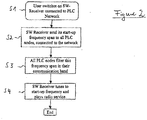
- Fig. 2 shows the working mechanism of the communication system 1 in a state when the radio receiver 2 is switched on.
- a first step S1 the user switches the radio receiver 2 (here: the SW-receiver as an example) on.
- the radio receiver 2 which is connected to the powerline communication network (in particular to the first to fifth powerline communication network nodes 3 to 7) via the powerline communication modem 9 since in a second step S2 it starts up frequency span to all powerline communication network nodes connected to the powerline communication network (i.e. here: the first to fifth powerline communication network nodes 3 to 7).
- the powerline communication network nodes 3 to 7 filter this frequency span in their communication band in a third step S3 which means that no frequencies lying within said frequency span are used during a powerline communication process.
- a fourth step S4 the radio receiver 2 tunes to a start-up frequency lying within the start-up frequency span and plays a corresponding radio service. Since this start-up frequency is not used during a powerline communication process, no distortions within radio signals can be caused by the powerline communication network.
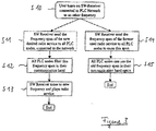
- a first step S10 the user tunes the radio receiver 2 from the start-up frequency to another frequency.
- the radio receiver 2 in response sends in a second step S 11 a frequency span containing the frequency of the new desired radio service to all powerline communication network nodes 3 to 7.
- the powerline communication network nodes 3 to 7 filter this frequency span in their communication band in a third step S12.
- the radio receiver 2 tunes to the new frequency corresponding to the new desired radio service and plays this service in a fourth step S 13.
- the radio receiver 2 informs all powerline communication network nodes 3 to 7 that the frequency span "blocked" during the time the first radio service was played can be reused in a fifth step S14.
- all powerline communication network use can then reuse the old frequency span in their communication band again in a sixth step S15.
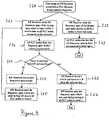
- a user scans on the radio receiver 2 to the next usable frequency in a first step S20. Then, in a second step S21, the radio receiver 2 sends a frequency span where it currently tunes within a certain time to the powerline communication network nodes 3 to 7. Then, in a third step S22, all powerline communication network nodes 3 to 7 filter this frequency span in their communication band, i.e. they do not use this frequency span when communicating between the powerline communication network nodes.
- the radio receiver judges in a fourth step S23, if already a new radio service has been found. If no new radio service has been found, the radio receiver 2 chooses a new frequency span and scans this frequency span for a new usable frequency in a fifth step S24. Then, the radio receiver 2 sends the frequency span which had been last scanned for a new usable frequency to all powerline communication network nodes 3 to 7 in order to free this frequency span. This is done in a sixth step S25. After this step, the radio receiver 2 returns to the second step S21 and executes the third and the fourth step S22, S23 as long a new usable frequency has been found.
- the radio receiver 2 tunes to the radio service corresponding to the new frequency in a seventh step S26. Then, the radio receiver 2 sends the complete frequency span which was used during the tuning process to all power line communication network nodes 3 to 7 to reuse it (except of the frequency corresponding to the new service being played). This is done in an eighth step S27. In addition to the first step S21, the radio receiver 2 sends in a ninth step S28 the frequency span of the former user radio service (radio service which was played before the tuning process) to all powerline communication network nodes 3 to 7. Then, in a tenth step S29, all powerline communication network nodes 3 to 7 can use this old frequency span in their communication band again.
- all powerline communication network nodes 3 to 7 are informed (or notify itself) that the radio receiver 2 is no more present.
- all power line communication network nodes 3 to 7 reuse the frequency span that was reserved by the radio receiver 2. This is done in a second step S31.
- powerline communication network refers to an entire network, for example all powerline communication network nodes.
- the radio receiver 2 sends via its powerline communication modem 9 to all powerline communication network nodes 3 to 7 the frequency span where the radio is actually tuning. This means if the radio is tuned to a fixed channel or to a range of channels in order to support alternative frequency switching, it sends the frequency of the channel(s) and the bandwidth of demodulation. If the radio receiver 2 is tuning or scanning the complete band to search for available radio stations, it sends the start and stop frequency of the scan to the powerline communication modem 9.
- the powerline communication modem 9 forwards the information of the frequency spectrum that has to be cleaned to all powerline communication network nodes 3 to 7. All powerline communication network nodes 3 to 7 have to filter this frequency span in their communication spectrum. So there are no unwanted distortions by powerline communication to radio reception.
- Receivers being not aware of this invention or portable receivers may not be equipped with a powerline communication modem 9. So there may be a human interface at any other device embedded with a powerline communication modem. The user may enter the frequency and the span of the channel that the receiver is tuned to and all powerline communication modems shall not use for powerline communication.
Landscapes
- Engineering & Computer Science (AREA)
- Power Engineering (AREA)
- Computer Networks & Wireless Communication (AREA)
- Signal Processing (AREA)
- Mobile Radio Communication Systems (AREA)
- Cable Transmission Systems, Equalization Of Radio And Reduction Of Echo (AREA)
Claims (10)
- Verfahren zum Betrieb eines Stromleitungs-Kommunikationsnetzes auf der Basis von Frequenzbereichen, die mit Frequenzbereichen zusammenfallen, die auch von Funkempfängern (2) verwendet werden, wobei das Stromleitungs-Kommunikationsnetz Stromleitungs-Kommunikationsnetzknoten (3 bis 7) aufweist, die über das Netz verbunden sind, wobei das Verfahren die folgenden Schritte aufweist:- Leiten von Frequenzwiederverwendungsinformationen zu den Netzknoten (3 bis 7) des Stromleitungs-Kommunikationsnetzes durch Verwendung des Stromleitungs-Kommunikationsnetzes, wobei die Frequenzwiederverwendungsinformationen einen zuvor für Verwendung durch die Funkempfänger zum Empfangen von Funksignalen reservierten Frequenzbereich definieren und wobei die Netzknoten zuvor betrieben wurden, um auf Frequenzen miteinander zu kommunizieren, die außerhalb des Frequenzbereichs der Funkempfänger liegen,- wobei die Netzknoten (3 bis 7) aktuell gemäß den Frequenzwiederverwendungsinformationen betrieben werden, um auf Frequenzen miteinander zu kommunizieren, die durch die Frequenzwiederverwendungsinformationen angegeben werden.
- Verfahren nach einem der vorhergehenden Ansprüche,
gekennzeichnet durch
Verwenden eines Stromleitungs-Kommunikationsmodems (9), um die Stromleitungs-Kommunikationsnetzknoten (3 bis 7) mit einem Funkempfänger (2) der Funkempfänger zu verbinden, um die Frequenzwiederverwendungsinformationen zu dem Stromleitungs-Kommunikationsnetzknoten (3 bis 7) zu leiten. - Verfahren nach einem der vorhergehenden Ansprüche,
dadurch gekennzeichnet, dass
die Frequenzwiederverwendungsinformationen mindestens teilweise durch einen Funkempfänger (2) der Funkempfänger erzeugt und dann zu dem Stromleitungs-Kommunikationsmodem (9) geleitet werden. - Verfahren nach einem der vorhergehenden Ansprüche,
dadurch gekennzeichnet, dass
die Frequenzwiederverwendungsinformationen mindestens teilweise durch eine Benutzereingabeschnittstelle (8) erzeugt oder empfangen und dann zu dem Stromleitungs-Kommunikationsmodem (9) geleitet werden. - Funkempfänger (2),
der Folgendes aufweist:- Mittel zum Erzeugen von Frequenzwiederverwendungsinformationen (10), die Frequenzen angeben, die in einem zuvor von Funkempfängern verwendeten Frequenzbereich liegen und für Stromleitungskommunikation wiederverwendete Frequenz sein sollen,- ein Stromleitungs-Kommunikationsmodem (9), das mit den Mitteln zum Erzeugen von Frequenzwiederverwendungsinformationen (10) verbunden ist und dafür ausgelegt ist, mit Netzknoten (3 bis 7) eines Stromleitungs-Kommunikationsnetzes verbunden zu werden,- wobei das Stromleitungs-Kommunikationsmodem (9) dafür ausgelegt ist, die Frequenzwiederverwendungsinformationen zu den Netzknoten (3 bis 7) weiterzuleiten, um mit ihnen verbunden zu werden, so dass die Netzknoten (3 bis 7) gemäß den Frequenzwiederverwendungsinformationen betrieben werden, um auf Frequenzen miteinander zu kommunizieren, die durch die Frequenzwiederverwendungsinformationen angegeben werden. - Funkempfänger (2) nach Anspruch 5,
dadurch gekennzeichnet, dass
die Mittel zum Erzeugen von Frequenzwiederverwendungsinformationen (10) eine Tuner-Verarbeitungseinheit (10) sind. - Stromleitungs-Kommunikationsnetzknoten (3 bis 7), der dafür ausgelegt ist, Teil eines Stromleitungs-Kommunikationsnetzes zu sein, das Stromleitungs-Kommunikationsnetzknoten (3 bis 7) aufweist, die über das Netz verbunden sind, wobei das Netz auf der Basis von Frequenzbereichen arbeitet, die mit auch von Funkempfängern verwendeten Frequenzbereichen zusammenfallen,
und Folgendes aufweist:- Mittel zum Empfangen von Frequenzwiederverwendungsinformationen durch Verwendung des Stromleitungs-Kommunikationsnetzes, die Frequenzen angeben, die in einem zuvor von Funkempfängern verwendeten Frequenzbereich liegen und für Stromleitungs-Kommunikation durch die Netzknoten wiederverwendet werden sollen, wobei die Frequenzwiederverwendungsinformationen einen zuvor für Verwendung durch die Funkempfänger zum Empfangen von Funksignalen reservierten Frequenzbereich definieren und wobei die Netzknoten zuvor so betrieben wurden, dass sie auf Frequenzen miteinander kommunizieren, die außerhalb des Frequenzbereichs der Funkempfänger liegen,- Mittel zum Anpassen seines Betriebs gemäß den Frequenzwiederverwendungsinformationen, um auf Frequenzen mit anderen Stromleitungs-Kommunikationsnetzknoten (3 bis 7) zu kommunizieren, die durch die Frequenzwiederverwendungsinformationen angegeben werden. - Kommunikationssystem (1),
das Folgendes aufweist:- den Funkempfänger (2) nach einem der Ansprüche 5 und 6,- mindestens einen Stromleitungs-Kommunikationsnetzknoten (3 bis 7) nach Anspruch 7,- wobei das Stromleitungs-Kommunikationsmodem (9) über ein Stromleitungs-Kommunikationsnetz mit dem mindestens einen Stromleitungs-Kommunikationsnetzknoten (3 bis 7) verbunden ist. - Computerprogrammprodukt mit Computerprogrammmitteln, die dafür ausgelegt sind, das Verfahren nach einem der Ansprüche 1 bis 4 auszuführen oder zu realisieren, wenn sie auf einem Computer ausgeführt werden.
- Computerlesbares Speichermittel, das dafür ausgelegt ist, das Computerprogrammprodukt nach Anspruch 9 zu speichern.
Priority Applications (1)
| Application Number | Priority Date | Filing Date | Title |
|---|---|---|---|
| EP17162408.3A EP3203644B1 (de) | 2002-10-11 | 2002-10-11 | Verfahren zum betrieb eines stromleitungskommunikationsnetzes |
Applications Claiming Priority (2)
| Application Number | Priority Date | Filing Date | Title |
|---|---|---|---|
| EP17162408.3A EP3203644B1 (de) | 2002-10-11 | 2002-10-11 | Verfahren zum betrieb eines stromleitungskommunikationsnetzes |
| EP02022807.8A EP1408622B1 (de) | 2002-10-11 | 2002-10-11 | Verfahren zum Betrieb eines Niederspannungnetzs |
Related Parent Applications (2)
| Application Number | Title | Priority Date | Filing Date |
|---|---|---|---|
| EP02022807.8A Division EP1408622B1 (de) | 2002-10-11 | 2002-10-11 | Verfahren zum Betrieb eines Niederspannungnetzs |
| EP02022807.8A Division-Into EP1408622B1 (de) | 2002-10-11 | 2002-10-11 | Verfahren zum Betrieb eines Niederspannungnetzs |
Publications (2)
| Publication Number | Publication Date |
|---|---|
| EP3203644A1 EP3203644A1 (de) | 2017-08-09 |
| EP3203644B1 true EP3203644B1 (de) | 2019-07-17 |
Family
ID=32010969
Family Applications (2)
| Application Number | Title | Priority Date | Filing Date |
|---|---|---|---|
| EP17162408.3A Expired - Lifetime EP3203644B1 (de) | 2002-10-11 | 2002-10-11 | Verfahren zum betrieb eines stromleitungskommunikationsnetzes |
| EP02022807.8A Expired - Lifetime EP1408622B1 (de) | 2002-10-11 | 2002-10-11 | Verfahren zum Betrieb eines Niederspannungnetzs |
Family Applications After (1)
| Application Number | Title | Priority Date | Filing Date |
|---|---|---|---|
| EP02022807.8A Expired - Lifetime EP1408622B1 (de) | 2002-10-11 | 2002-10-11 | Verfahren zum Betrieb eines Niederspannungnetzs |
Country Status (1)
| Country | Link |
|---|---|
| EP (2) | EP3203644B1 (de) |
Family Cites Families (4)
| Publication number | Priority date | Publication date | Assignee | Title |
|---|---|---|---|---|
| US4479215A (en) * | 1982-09-24 | 1984-10-23 | General Electric Company | Power-line carrier communications system with interference avoidance capability |
| JPS61101126A (ja) | 1984-10-23 | 1986-05-20 | Matsushita Electric Ind Co Ltd | 搬送波重畳通信装置 |
| GB9407934D0 (en) * | 1994-04-21 | 1994-06-15 | Norweb Plc | Transmission network and filter therefor |
| GB9828373D0 (en) | 1998-12-22 | 1999-02-17 | Northern Telecom Ltd | A power line communication system and method of operation thereof |
-
2002
- 2002-10-11 EP EP17162408.3A patent/EP3203644B1/de not_active Expired - Lifetime
- 2002-10-11 EP EP02022807.8A patent/EP1408622B1/de not_active Expired - Lifetime
Non-Patent Citations (1)
| Title |
|---|
| None * |
Also Published As
| Publication number | Publication date |
|---|---|
| EP3203644A1 (de) | 2017-08-09 |
| EP1408622A1 (de) | 2004-04-14 |
| EP1408622B1 (de) | 2017-07-26 |
Similar Documents
| Publication | Publication Date | Title |
|---|---|---|
| US6195563B1 (en) | Radio receiver and radio transmitter | |
| JP3348196B2 (ja) | 無線伝送システム | |
| EP2140555B1 (de) | Verfahren und vorrichtung für adaptive kanalverwendung | |
| US6201968B1 (en) | Method combining entries from multiple neighbor cell lists to obtain an updated list for a subscriber device | |
| CN1135687C (zh) | 一种射频收发信机和收发射频信号的方法 | |
| US20080233954A1 (en) | Method And System For Processing Results Derived From Detecting Channels Suitable For FM Transmission In An Integrated FM Transmit/Receive System | |
| KR20010033776A (ko) | 무선 통신 네트워크의 방법 및 장치 | |
| US6628927B1 (en) | Method and apparatus for transmitting and receiving signals | |
| WO1998043366A1 (en) | Dual band mobile station | |
| US20050124351A1 (en) | Method and apparatus for establishing direct mobile to mobile communication between cellular mobile terminals | |
| CN1275296A (zh) | 双模式移动电话 | |
| EP3203644B1 (de) | Verfahren zum betrieb eines stromleitungskommunikationsnetzes | |
| WO2002011297A2 (en) | Apparatus, and associated method, for receiving data at a radio device | |
| CN1128452A (zh) | 能抑制杂散干扰的电话和无绳电话 | |
| KR100302096B1 (ko) | 이동통신 단말기를 이용한 차량 원격 제어장치 | |
| JP4604433B2 (ja) | 無線通信装置および方法 | |
| JPH1168603A (ja) | マイクロ波信号を受信する回路用のコマンドプロトコル及びプロトコル実施装置 | |
| EP1240721B1 (de) | Frequenzerzeugung für cdma-endgerät mit zeitgeschlitzten empfangsmodus | |
| US20040214544A1 (en) | Apparatus and method for the avoidance of RF interference | |
| US20040121744A1 (en) | Method and apparatus for producing mobile radio signals | |
| WO2001045314A2 (en) | System and method for pulsed cable telephony | |
| JP3559138B2 (ja) | 双方向回線の通信装置 | |
| JP2011166420A (ja) | テレビ放送受信機能付き携帯電話機およびその制御方法 | |
| JP3208333B2 (ja) | 親子電話装置の空チャネル検索方式 | |
| US20020086686A1 (en) | Programmable radio receiver bandpass filter for cordless/wireless systems |
Legal Events
| Date | Code | Title | Description |
|---|---|---|---|
| PUAI | Public reference made under article 153(3) epc to a published international application that has entered the european phase |
Free format text: ORIGINAL CODE: 0009012 |
|
| 17P | Request for examination filed |
Effective date: 20170322 |
|
| AC | Divisional application: reference to earlier application |
Ref document number: 1408622 Country of ref document: EP Kind code of ref document: P |
|
| AK | Designated contracting states |
Kind code of ref document: A1 Designated state(s): DE FR GB |
|
| 17Q | First examination report despatched |
Effective date: 20180103 |
|
| GRAP | Despatch of communication of intention to grant a patent |
Free format text: ORIGINAL CODE: EPIDOSNIGR1 |
|
| INTG | Intention to grant announced |
Effective date: 20181019 |
|
| GRAJ | Information related to disapproval of communication of intention to grant by the applicant or resumption of examination proceedings by the epo deleted |
Free format text: ORIGINAL CODE: EPIDOSDIGR1 |
|
| INTC | Intention to grant announced (deleted) | ||
| GRAP | Despatch of communication of intention to grant a patent |
Free format text: ORIGINAL CODE: EPIDOSNIGR1 |
|
| INTG | Intention to grant announced |
Effective date: 20190225 |
|
| GRAS | Grant fee paid |
Free format text: ORIGINAL CODE: EPIDOSNIGR3 |
|
| GRAA | (expected) grant |
Free format text: ORIGINAL CODE: 0009210 |
|
| AC | Divisional application: reference to earlier application |
Ref document number: 1408622 Country of ref document: EP Kind code of ref document: P |
|
| AK | Designated contracting states |
Kind code of ref document: B1 Designated state(s): DE FR GB |
|
| REG | Reference to a national code |
Ref country code: GB Ref legal event code: FG4D |
|
| REG | Reference to a national code |
Ref country code: DE Ref legal event code: R096 Ref document number: 60249955 Country of ref document: DE |
|
| REG | Reference to a national code |
Ref country code: DE Ref legal event code: R097 Ref document number: 60249955 Country of ref document: DE |
|
| PLBE | No opposition filed within time limit |
Free format text: ORIGINAL CODE: 0009261 |
|
| STAA | Information on the status of an ep patent application or granted ep patent |
Free format text: STATUS: NO OPPOSITION FILED WITHIN TIME LIMIT |
|
| 26N | No opposition filed |
Effective date: 20200603 |
|
| PGFP | Annual fee paid to national office [announced via postgrant information from national office to epo] |
Ref country code: FR Payment date: 20210921 Year of fee payment: 20 |
|
| PGFP | Annual fee paid to national office [announced via postgrant information from national office to epo] |
Ref country code: GB Payment date: 20210922 Year of fee payment: 20 |
|
| PGFP | Annual fee paid to national office [announced via postgrant information from national office to epo] |
Ref country code: DE Payment date: 20210921 Year of fee payment: 20 |
|
| REG | Reference to a national code |
Ref country code: DE Ref legal event code: R071 Ref document number: 60249955 Country of ref document: DE |
|
| REG | Reference to a national code |
Ref country code: GB Ref legal event code: PE20 Expiry date: 20221010 |
|
| PG25 | Lapsed in a contracting state [announced via postgrant information from national office to epo] |
Ref country code: GB Free format text: LAPSE BECAUSE OF EXPIRATION OF PROTECTION Effective date: 20221010 |