EP3203652B1 - Basisstationsvorrichtung in mobilkommunikationssystem - Google Patents
Basisstationsvorrichtung in mobilkommunikationssystem Download PDFInfo
- Publication number
- EP3203652B1 EP3203652B1 EP14903153.6A EP14903153A EP3203652B1 EP 3203652 B1 EP3203652 B1 EP 3203652B1 EP 14903153 A EP14903153 A EP 14903153A EP 3203652 B1 EP3203652 B1 EP 3203652B1
- Authority
- EP
- European Patent Office
- Prior art keywords
- circulator
- terminal
- antenna
- duplexer
- path
- Prior art date
- Legal status (The legal status is an assumption and is not a legal conclusion. Google has not performed a legal analysis and makes no representation as to the accuracy of the status listed.)
- Active
Links
Images

Classifications
-
- H—ELECTRICITY
- H04—ELECTRIC COMMUNICATION TECHNIQUE
- H04B—TRANSMISSION
- H04B7/00—Radio transmission systems, i.e. using radiation field
- H04B7/02—Diversity systems; Multi-antenna system, i.e. transmission or reception using multiple antennas
- H04B7/04—Diversity systems; Multi-antenna system, i.e. transmission or reception using multiple antennas using two or more spaced independent antennas
- H04B7/06—Diversity systems; Multi-antenna system, i.e. transmission or reception using multiple antennas using two or more spaced independent antennas at the transmitting station
-
- H—ELECTRICITY
- H04—ELECTRIC COMMUNICATION TECHNIQUE
- H04B—TRANSMISSION
- H04B1/00—Details of transmission systems, not covered by a single one of groups H04B3/00 - H04B13/00; Details of transmission systems not characterised by the medium used for transmission
- H04B1/0003—Software-defined radio [SDR] systems, i.e. systems wherein components typically implemented in hardware, e.g. filters or modulators/demodulators, are implented using software, e.g. by involving an AD or DA conversion stage such that at least part of the signal processing is performed in the digital domain
- H04B1/0028—Software-defined radio [SDR] systems, i.e. systems wherein components typically implemented in hardware, e.g. filters or modulators/demodulators, are implented using software, e.g. by involving an AD or DA conversion stage such that at least part of the signal processing is performed in the digital domain wherein the AD/DA conversion occurs at baseband stage
- H04B1/0035—Channel filtering, i.e. selecting a frequency channel within a software radio system
-
- H—ELECTRICITY
- H04—ELECTRIC COMMUNICATION TECHNIQUE
- H04B—TRANSMISSION
- H04B1/00—Details of transmission systems, not covered by a single one of groups H04B3/00 - H04B13/00; Details of transmission systems not characterised by the medium used for transmission
- H04B1/38—Transceivers, i.e. devices in which transmitter and receiver form a structural unit and in which at least one part is used for functions of transmitting and receiving
- H04B1/40—Circuits
- H04B1/50—Circuits using different frequencies for the two directions of communication
- H04B1/52—Hybrid arrangements, i.e. arrangements for transition from single-path two-direction transmission to single-direction transmission on each of two paths or vice versa
-
- H—ELECTRICITY
- H04—ELECTRIC COMMUNICATION TECHNIQUE
- H04B—TRANSMISSION
- H04B7/00—Radio transmission systems, i.e. using radiation field
- H04B7/02—Diversity systems; Multi-antenna system, i.e. transmission or reception using multiple antennas
- H04B7/022—Site diversity; Macro-diversity
- H04B7/024—Co-operative use of antennas of several sites, e.g. in co-ordinated multipoint or co-operative multiple-input multiple-output [MIMO] systems
-
- H—ELECTRICITY
- H04—ELECTRIC COMMUNICATION TECHNIQUE
- H04B—TRANSMISSION
- H04B7/00—Radio transmission systems, i.e. using radiation field
- H04B7/02—Diversity systems; Multi-antenna system, i.e. transmission or reception using multiple antennas
- H04B7/022—Site diversity; Macro-diversity
- H04B7/026—Co-operative diversity, e.g. using fixed or mobile stations as relays
-
- H—ELECTRICITY
- H04—ELECTRIC COMMUNICATION TECHNIQUE
- H04B—TRANSMISSION
- H04B7/00—Radio transmission systems, i.e. using radiation field
- H04B7/02—Diversity systems; Multi-antenna system, i.e. transmission or reception using multiple antennas
- H04B7/04—Diversity systems; Multi-antenna system, i.e. transmission or reception using multiple antennas using two or more spaced independent antennas
- H04B7/0413—MIMO systems
-
- H—ELECTRICITY
- H04—ELECTRIC COMMUNICATION TECHNIQUE
- H04B—TRANSMISSION
- H04B7/00—Radio transmission systems, i.e. using radiation field
- H04B7/14—Relay systems
- H04B7/15—Active relay systems
- H04B7/155—Ground-based stations
-
- H—ELECTRICITY
- H04—ELECTRIC COMMUNICATION TECHNIQUE
- H04L—TRANSMISSION OF DIGITAL INFORMATION, e.g. TELEGRAPHIC COMMUNICATION
- H04L27/00—Modulated-carrier systems
- H04L27/18—Phase-modulated carrier systems, i.e. using phase-shift keying
- H04L27/22—Demodulator circuits; Receiver circuits
- H04L27/233—Demodulator circuits; Receiver circuits using non-coherent demodulation
- H04L27/2334—Demodulator circuits; Receiver circuits using non-coherent demodulation using filters
Definitions
- the present disclosure in some embodiments, relates to a base station including a repeater for a mobile communication (PCS, Cellular, CDMA, GSM, LTE, etc.) system. More particularly, the present disclosure relates to a base station device in a mobile communication system for providing enhanced isolation between a transmitted signal and a received signal which are processed using a Multiple Input Multiple Output (MIMO) scheme.
- MIMO Multiple Input Multiple Output
- An antenna used in a base station including a repeater for a wireless communication system can have various forms and structures.
- a dual polarization antenna structure of 2T2R (2Tx / 2Rx) MIMO scheme has been widely employed in wireless communication antennas by applying a polarization diversity scheme.
- the signals of the respective transmission & reception paths generally employ a structure for isolating transmitted and received signals using duplexers.
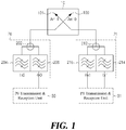
- FIG. 1 is a schematic block diagram of a prior art base station apparatus of a mobile communication system.
- FIG. 1 shows an antenna system 10 having a 2T2R MIMO structure used in a typical mobile communication base station, and first and second duplexers 20 and 21 provided to each transmission & reception path.
- the antenna system 10 includes a first antenna (Ant0) 100 for transmitting and receiving signals for a first path P0 and a second antenna (Ant1) 101 for transmitting and receiving signals for a second path P1 in a 2T2R structure.
- the first and second antennas 100 and 101 are arranged to generate polarized waves orthogonal to each other.
- first and second duplexers 20 and 21 respectively connected to the first and second antennas 100 and 101 of the antenna system 10 to separate or combine the transmitted and received signals of the first and second paths P0 and P1 are provided.
- the first duplexer 20 is connected to a first transmission & reception unit (P0 transmission & reception unit) 30, and the second duplexer 21 is connected to a second transmission & reception unit (P1 transmission & reception unit) 31.
- the first transmission & reception unit 30 processes signals transmitted and received on the first path
- the second transmission & reception unit 31 processes signals transmitted and received on the second path PI.
- the first duplexer 20 has a structure in which a transmission filter (Tx0) 204 and a reception filter (Rx0) 206, which process a transmitted signal and a received signal for the first path P0, respectively, are connected using a T-junction 202.
- the second duplexer 21 has a structure in which a transmission filter (Tx1) 214 and a reception filter (Rx1) 216, which process a transmitted signal and a received signal for the second path P1, are connected using a T-junction 212.
- isolation between the transmitted signal and the received signal on the first path P0 is determined by the first duplexer 20 including the transmission filter 204 and the reception filter 206 connected by the T-junction 202. That is, isolation between the transmitting terminal and the receiving terminal of the first duplexer 20 is the transmission and reception isolation on the first path P0. Similarly, isolation of the transmitted signal and the received signal on the second path P1 corresponds to the isolation produced in implementing the second duplexer 21 including the transmission filter 214 and the reception filter 216 connected by the T-junction 212.
- filtering characteristics for example, skirt characteristic
- a technique of increasing the number of stages of each of the transmission filter and the reception filter or increasing the number of notches at a frequency to be isolated is generally employed.
- such a solution has problems of increasing the size of filters and difficulty in manufacture and production of filters.
- US 2013/162495 A1 for example describes a base station apparatus of a mobile communication system using radio-frequency passive elements, which includes a plurality of band pass filters configured a transmission signal and a reception signal, a first circulator configured to output a first transmission signal to a second terminal and output a second reception signal input; a second circulator configured to output a second transmission signal input into the first terminal to the second terminal and output a first reception signal input into the second terminal to the third terminal; a passive directional double pole and double throw switch configured to process a route to be changed depending on directions of an input and an output; a first antenna configured to transmit the first transmission signal; and a second antenna configured to transmit the second transmission.
- a base station apparatus of a mobile communication system using radio-frequency passive elements which includes a plurality of band pass filters configured a transmission signal and a reception signal, a first circulator configured to output a first transmission signal to a second terminal and output a second reception signal input; a second circulator configured to output a second transmission signal input into the first terminal
- each base station is being evolved into a small (or micro) cell, and an antenna system and base station equipment are being developed in an integrated manner. Accordingly, there is growing demand for a more compact and lightweight duplexer including the transmission filter and the reception filter described above. It has been a very difficult challenge to increase isolation between the transmitted signal and the received signal in consideration of the size and weight of the duplexer as described above.
- the present disclosure has been made in an effort to effectively resolve the aforementioned problems, and it is an object of the present disclosure to provide a device configured to increase isolation between the transmitted signal and received signal on a transmission & reception path or maintaining or satisfying a certain required level of isolation while reducing the size and weight of a duplexer configured to process the transmitted and received signals.
- a base station apparatus of a mobile communication system includes an antenna system, a duplexer, a reception filter and a path change unit.
- the antenna system includes a first antenna configured to transmit and receive a signal for a first path among Multiple Input Multiple Output (MIMO) paths, and a second antenna configured to transmit and receive a signal for a second path among the MIMO paths.
- the duplexer includes a transmission filter configured to process the transmitted signal of the first path and a reception filter configured to process the received signal of the second path.
- the reception filter is configured to process the received signal of the first path.
- the path change unit is configured to deliver the transmitted signal provided by the duplexer to the first antenna, to deliver the received signal provided by the first antenna to the reception filter, and to deliver the received signal provided by the second antenna to the duplexer.
- an apparatus for providing isolation between a transmitted signal and a received signal may obtain not only isolation in a duplexer for processing the transmitted and received signals but also additional isolation between the transmitted and received signals ranging from 30 dB to 50 dB.
- the conventional duplexer for processing transmitted and received signals depends on the isolation characteristics of the filter structure itself, it requires a relatively large number (more than one) of resonators and notch structures to obtain a desired isolation.
- a desired isolation may be obtained with a relatively small number of resonators under the same conditions, and the number of notch structures may be reduced, which makes it possible to implement smaller and lighter filters and duplexers while satisfying desired high performance.
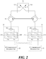
- FIG. 2 is a schematic block diagram of a base station apparatus of a mobile communication system, according to a first embodiment of the present disclosure. Similar to the prior art example shown in FIG. 1 , FIG. 2 shows an antenna system 10 of a 2T2R MIMO structure used in a typical mobile communication base station and first and second duplexers 20 and 21 provided in respective transmission & reception paths thereof.
- the antenna system 10 includes a first antenna (Ant0) 100 configured to transmit and receive signals for a first path P0 and a second antenna (Ant1) 101 configured to transmit and receive for a second path P1 in a 2T2R structure.
- the first and second antennas 100 and 101 are arranged to generate polarized waves orthogonal to each other.
- a path change unit is provided between the first and second duplexers 20 and 21.
- the path change unit changes the first and second trasnmnission & received signal paths to provide a transmitted signal from the first duplexer 20 to the first antenna 100 and a received signal from the first antenna 100 to the second duplexer 21 and to provide a transmitted signal from the second duplexer 21 to the second antenna 101 and a received signal from the second antenna 101 to the first duplexer 20.
- a pair of a first circulator 40 and a second circulator 41 may be configured.
- the first circulator 40 is connected to the first duplexer 20 through terminal 1, terminal 2 is connected to the first antenna 100, and terminal 3 is connected to terminal 3 of the second circulator 41.
- a signal input through terminal 1 is output through terminal 2
- a signal input through terminal 2 is output through terminal 3
- a signal input through terminal 3 is output through terminal 1.
- the second circulator 41 is connected to the second duplexer 21 through terminal 1, terminal 2 is connected to the second antenna 101, and terminal 3 is connected to terminal 3 of the first circulator 40.
- a signal input through terminal 1 is output through terminal 2
- a signal input through terminal 2 is output through terminal 3
- a signal input through terminal 3 is output through terminal 1.
- the first and second duplexers 20 and 21 are connected to the first and second antennas 100 and 101 of the antenna system 10, respectively, to separate or combine the transmitted and received signals of the first and second paths P0 and P1.
- the first duplexer 20 includes not only a transmission filter 204 configured to process a transmitted signal of the first transmission & reception unit (P0 transmission & reception unit) 30, but also a reception filter 206' configured to process a received signal of the second transmission & reception unit (P1 transmission & reception unit) 31.
- the hardware structure of the first duplexer 20 may be substantially the same as that of the conventional structure shown in FIG. 1 .
- the reception filter 206' is connected to the second transmission & reception unit 31 and is used to filter the received signal of the second path.
- the second duplexer 21 includes a transmission filter 214 configured to process a transmitted signal of the second transmission & reception unit (P1 transmission & reception unit) 31 and a reception filter 216' configured to process a received signal of the first transmission & reception unit 30. That is, the reception filter 216' is connected to the first transmission & reception unit 30 and the second duplexer 21 is used to filter the received signal of the first path.
- the first duplexer 20 has a structure in which the transmission filter 204 configured to process a transmitted signal for the first path and the reception filter 206' configured to process a received signal for the second path are connected using a T-junction 202
- the second duplexer 21 has a structure in which the transmission filter 214 configured to process a transmitted signal for the second path and the reception filter 216' configured to process a received signal for the first path are connected using a T-junction 212.
- a signal transmitted from the transmission filter 204 of the first path of the first duplexer 20 is provided to the first antenna 100 of the antenna system 10 via the first circulator 40 and is radiated to the air.
- a received signal of the first path in the air is received through the first antenna 101 and provided to the second circulator 41 via the first circulator 40.
- the received signal is provided to the reception filter 216' of the first path of the second duplexer 21.
- the transmitted signal and the received signal of the first path are separated by the first duplexer 20 and the second duplexer 21 and are thus perfectly isolated from each other.
- a signal transmitted from the transmission filter 214 of the second path of the second duplexer 21 is provided to the second antenna 101 of the antenna system 10 via the second circulator 41, and is then radiated to the air.
- a received signal of the second path in the air is received through the second antenna 101, provided to the second circulator 41, and then provided to the first circulator 40 from the second circulator 41. Thereafter, the received signal is provided to the reception filter 206' of the first path of the first duplexer 20.
- the transmitted signal and the received signal of the second path are separated by the first duplexer 20 and the second duplexer 21 and are thus perfectly isolated from each other.
- the apparatus according to the present disclosure structurally increases isolation between the transmitting terminal and the receiving terminal in a 2T2R (or higher) MIMO base station using the directionality of the circulators 40 and 41.
- the first and second antennas 100 and 101 are arranged such that the antennas are orthogonal to each other.
- the transmitted and received signals between the antennas 100 and 101 typically have an isolation of about 30 dB due to orthogonality between the antennas 100 and 101.
- isolation is determined by the isolation characteristics of the transmission filter 204 of the first path. Since the transmission filter 204 of the first path and the reception filter 206' of the second path are connected to the first antenna 100 and the second antenna 101, respectively, an isolation of about 30 dB is given by orthogonality between the antennas 100 and 101. Accordingly, the transmitted signal of the first path and the received signal of the second path obtain isolation of the antennas 100 and 101 in addition to isolation of the transmission & reception filters 204 and 206'. Similarly, the transmitted signal of the second path and the received signal of the first path obtain isolation of the antennas 100 and 101 in addition to isolation of the transmission & reception filters 214 and 216'.
- isolation between the transmitted signal and the received signal obtains not only inherent isolation of the duplexers but also additional isolation of about 30 dB between the transmitted and received signals, which is obtained by orthogonality of the antennas. Accordingly, when the isolation required between the transmitted signal and the received signal is, for example, 90 dB, the duplexers of the present disclosure only need to satisfy isolation of about 60 dB. In contrast, in the prior art, since the isolation of 90 dB should be satisfied using only the duplexers, there is a greater difficulty in terms of structure and size in implementing the duplexers.
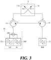
- FIG. 3 is a schematic block diagram of a base station apparatus of a mobile communication system, according to a second embodiment of the present disclosure.
- the structure according to the second embodiment shown in FIG. 3 is almost the same as the structure according to the first embodiment shown in FIG. 2 except that instead of the second duplexer 21, the reception filter 23 of the first path is connected to terminal 1 of the second circulator 41.
- the configuration and operation of the structure shown in FIG. 3 are the same as those of the structure according to the first embodiment shown in FIG. 2 except that the structure shown in FIG. 3 does not have a configuration and operation related to the processing of the transmitted signal of the second path. That is, while the structure of the first embodiment shown in FIG. 2 is employed to implement the 2T2R MIMO scheme, the structure shown in FIG. 3 is intended to implement the 1T2R MIMO scheme.
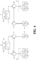
- FIG. 4 is a schematic block diagram of a base station apparatus of a mobile communication system, according to a third embodiment of the present disclosure.
- the structure according to the third embodiment shown in FIG. 4 substantially employs two of the structure of the second embodiment shown in FIG. 3 . That is, the structure shown in FIG. 4 is provided to implement a 2T4R MIMO scheme by doubling the 1T2R MIMO scheme shown in FIG. 3 .
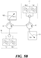
- FIGs. 5A and 5B are diagrams of modified embodiments of the present disclosure.
- the directionality of the first circulator 40 is the forward direction (clockwise direction) and the directionality of the second circulator 41 is the reverse direction (counterclockwise direction).
- the directionality of the second circulator 41 is the reverse direction (counterclockwise direction).
- a combined pair of forward circulators (a, b) has a nonreciprocal circuit topology with four signal cyclic transfer terminals.
- a first duplexer 20, a first antenna 100, a second duplexer 21, and a second antenna 101 are connected to respective terminals of the forward-circulator pair 40, 42 shown in FIG. 5B .
- a structure logically identical to the structure of the first embodiment shown in FIG. 2 may be implemented.
- An apparatus for providing isolation between the transmitted signal and the received signal according to an embodiment of the present disclosure can be configured as described above. While the present disclosure has been particularly shown and described with reference to exemplary embodiments thereof, it is to be understood that various modifications may be made without departing from the scope of the present invention.
- isolation may be secured by arranging the two antennas not orthogonal to each other but spatially spaced apart from each other by an appropriate distance.
- this structure may be doubled (or n-tuple) to implement a 4T4R (or higher) MIMO scheme.
- duplexers While the structure of the duplexers is illustrated as being implemented using a T-junction structure in the second and third embodiments shown in FIGS. 3 and 4 , the structure of the duplexers may employ a structure using the circulator shown in FIG. 3 .
Landscapes
- Engineering & Computer Science (AREA)
- Computer Networks & Wireless Communication (AREA)
- Signal Processing (AREA)
- Transceivers (AREA)
- Variable-Direction Aerials And Aerial Arrays (AREA)
- Mobile Radio Communication Systems (AREA)
Claims (6)
- Basisstationsvorrichtung eines mobilen Kommunikationssystems, wobei die Basisstationsvorrichtung umfasst:ein Antennensystem (10), umfassend eine erste Antenne (100), die konfiguriert ist, um ein Signal für einen ersten Pfad zwischen Multiple Input Multiple Output MIMO-Pfaden zu senden und zu empfangen, und eine zweite Antenne (101), die konfiguriert ist, um ein Signal für einen zweiten Pfad zwischen den MIMO-Pfaden zu senden und zu empfangen;einen ersten Duplexer (20), der einen Sendefilter (204) umfasst, der konfiguriert ist, um ein Sendesignal des ersten Pfades zu verarbeiten, und einen Empfangsfilter (206'), der konfiguriert ist, um ein empfangenes Signal des zweiten Pfades zu verarbeiten;einen zweiten Duplexer (21), umfassend einen Empfangsfilter (216'), der konfiguriert ist, um ein empfangenes Signal des ersten Pfades zu verarbeiten, und einen Sendefilter (214), der konfiguriert ist, um ein gesendetes Signal des zweiten Pfades zu verarbeiten; undeine Pfadänderungseinheit, die konfiguriert ist zumliefern des von dem ersten Duplexer (20) bereitgestellten Sendesignals an die erste Antenne (100),liefern eines von der ersten Antenne (100) bereitgestellten Empfangssignals an den zweiten Duplexer (21),liefern des von dem zweiten Duplexer (21) bereitgestellten Sendesignals an die zweite Antenne (101), undliefern eines von der zweiten Antenne (101) bereitgestellten Empfangssignals an den ersten Duplexer (20), dadurch gekennzeichnet, dass die Wegänderungseinheit einen ersten Zirkulator (40) und einen zweiten Zirkulator (40, 41) umfasst,wobei der erste Zirkulator (40) erste, zweite und dritte Anschlüsse aufweist, die mit dem ersten Duplexer (20), der ersten Antenne (100) bzw. einem dritten Anschluss des zweiten Zirkulators (41) verbunden sind, und ein über den ersten Anschluss des ersten Zirkulators (40) eingegebenes Signal über den zweiten Anschluss des ersten Zirkulators (40) ausgegeben wird, ein über den zweiten Anschluss des ersten Zirkulators (40) eingegebenes Signal über den dritten Anschluss des ersten Zirkulators (40) ausgegeben wird, und ein über den dritten Anschluss des ersten Zirkulators (40) eingegebenes Signal über den ersten Anschluss des ersten Zirkulators (40) ausgegeben wird,wobei der zweite Zirkulator (41) einen ersten und einen zweiten Anschluss aufweist und der dritte Anschluss mit dem zweiten Duplexer (21), der zweiten Antenne (101) bzw. dem dritten Anschluss des ersten Zirkulators (40) verbunden ist, und ein über den ersten Anschluss des zweiten Zirkulators (41) eingegebenes Signal über den zweiten Anschluss des zweiten Zirkulators (41) ausgegeben wird, ein über den zweiten Anschluss des zweiten Zirkulators (41) eingegebenes Signal über den dritten Anschluss des zweiten Zirkulators (41) ausgegeben wird, und ein über den dritten Anschluss des zweiten Zirkulators (41) eingegebenes Signal über den ersten Anschluss des zweiten Zirkulators (41) ausgegeben wird.
- Basisstationsvorrichtung nach Anspruch 1, wobei der erste Duplexer (20) und der zweite Duplexer (21) jeweils konfiguriert sind, um eine T-Verbindung (202, 212) zum Verbinden des Sendefilters (204, 214) und des Empfangsfilters (206', 216') zu enthalten.
- die Basisstationsvorrichtung nach einem der Ansprüche 1 oder 2, wobei die erste Antenne (100) und die zweite Antenne (101) angeordnet sind, um polarisierte Wellen orthogonal zueinander zu erzeugen.
- Basisstationsvorrichtung eines mobilen Kommunikationssystems, wobei die Basisstationsvorrichtung umfasst:ein Antennensystem (10), umfassend eine erste Antenne (100), die konfiguriert ist, um ein Signal für einen ersten Pfad zwischen MIMO-Pfaden (Multiple Input Multiple Output) zu senden und zu empfangen, und eine zweite Antenne (101), die konfiguriert ist, um ein Signal für einen zweiten Pfad zwischen den MIMO-Pfaden zu senden und zu empfangen;einen Duplexer (20), umfassend einen Sendefilter (204), der konfiguriert ist, um ein Sendesignal des ersten Pfades zu verarbeiten, und einen Empfangsfilter (206'), der konfiguriert ist, um ein Empfangssignal des zweiten Pfades zu verarbeiten;ein Empfangsfilter (216'), das konfiguriert ist, um ein Empfangssignal des ersten Pfades zu verarbeiten; undeine Pfadänderungseinheit, die konfiguriert ist umdas vom Duplexer (20) bereitgestellten Sendesignals an die erste Antenne zu liefern, ein von der ersten Antenne (100) bereitgestelltes Empfangssignal an den Empfangsfilter (206', 216') zu liefern undeines von der zweiten Antenne (101) bereitgestellten Empfangssignals an den Duplexer zu liegfern, dadurch gekennzeichnet, dass die Wegänderungseinheit einen ersten Zirkulator (40) und einen zweiten Zirkulator (41) umfasst;wobei der erste Zirkulator (40) erste, zweite und dritte Anschlüsse aufweist, die mit dem Duplexer, der ersten Antenne bzw. einem dritten Anschluss des zweiten Zirkulators (41) verbunden sind, und ein Signal, das über den ersten Anschluss des ersten Zirkulators (40) eingegeben wird, über den zweiten Anschluss des ersten Zirkulators (40) ausgegeben wird, ein über den zweiten Anschluss des ersten Zirkulators (40) eingegebenes Signal über den dritten Anschluss des ersten Zirkulators (40) ausgegeben wird, und ein über den dritten Anschluss des ersten Zirkulators (40) eingegebenes Signal über den ersten Anschluss des ersten Zirkulators (40) ausgegeben wird,wobei der zweite Zirkulator (41) einen ersten und einen zweiten Anschluss aufweist und der dritte Anschluss mit dem Empfangsfilter (206', 216'), der zweiten Antenne (101) bzw. dem dritten Anschluss des ersten Zirkulators (40) verbunden ist und ein über den ersten Anschluss des zweiten Zirkulators (41) eingegebenes Signal über den zweiten Anschluss des zweiten Zirkulators (41) ausgegeben wird, ein über den zweiten Anschluss des zweiten Zirkulators (41) eingegebenes Signal über den dritten Anschluss des zweiten Zirkulators (41) ausgegeben wird, und ein über den dritten Anschluss des zweiten Zirkulators (41) eingegebenes Signal über den ersten Anschluss des zweiten Zirkulators (41) ausgegeben wird.
- Basisstationsvorrichtung nach Anspruch 4, wobei der Duplexer konfiguriert ist, um eine T-Verbindung zum Verbinden des Sendefilters (204) und des Empfangsfilters (206', 216') zu enthalten.
- die Basisstationsvorrichtung nach einem der Ansprüche 4 oder 5, wobei die erste Antenne (100) und die zweite Antenne (101) angeordnet sind, um orthogonal zueinander polarisierte Wellen zu erzeugen.
Applications Claiming Priority (1)
| Application Number | Priority Date | Filing Date | Title |
|---|---|---|---|
| PCT/KR2014/009309 WO2016052782A1 (ko) | 2014-10-02 | 2014-10-02 | 이동통신 시스템의 기지국 장치 |
Publications (3)
| Publication Number | Publication Date |
|---|---|
| EP3203652A1 EP3203652A1 (de) | 2017-08-09 |
| EP3203652A4 EP3203652A4 (de) | 2018-05-23 |
| EP3203652B1 true EP3203652B1 (de) | 2020-01-01 |
Family
ID=55630800
Family Applications (1)
| Application Number | Title | Priority Date | Filing Date |
|---|---|---|---|
| EP14903153.6A Active EP3203652B1 (de) | 2014-10-02 | 2014-10-02 | Basisstationsvorrichtung in mobilkommunikationssystem |
Country Status (5)
| Country | Link |
|---|---|
| US (1) | US9917627B2 (de) |
| EP (1) | EP3203652B1 (de) |
| JP (1) | JP6408144B2 (de) |
| CN (1) | CN106797244B (de) |
| WO (1) | WO2016052782A1 (de) |
Families Citing this family (3)
| Publication number | Priority date | Publication date | Assignee | Title |
|---|---|---|---|---|
| CN109861715B (zh) * | 2017-11-30 | 2021-08-13 | 阿里巴巴集团控股有限公司 | 一种基站、基站系统和通信网络 |
| KR102392705B1 (ko) * | 2018-01-18 | 2022-05-03 | 삼성전자 주식회사 | 신호 경로 및 소자의 불량을 판단하는 전자 장치 및 전자 장치의 동작 방법 |
| CN109802699B (zh) * | 2019-01-24 | 2021-02-09 | 维沃移动通信有限公司 | 一种信号收发装置及终端设备 |
Family Cites Families (18)
| Publication number | Priority date | Publication date | Assignee | Title |
|---|---|---|---|---|
| JPS58188940A (ja) * | 1982-04-28 | 1983-11-04 | Nippon Telegr & Teleph Corp <Ntt> | 多分岐アンテナ装置 |
| JPH08331029A (ja) * | 1995-06-02 | 1996-12-13 | Fujitsu Ltd | 無線中継装置 |
| JPH09181660A (ja) * | 1995-12-26 | 1997-07-11 | Hitachi Ltd | 無線端末装置 |
| US6125109A (en) * | 1998-02-24 | 2000-09-26 | Repeater Technologies | Delay combiner system for CDMA repeaters and low noise amplifiers |
| ATE414998T1 (de) * | 2003-04-18 | 2008-12-15 | Nokia Siemens Networks Spa | Mikrowellen-duplexer mit dielektrischen filtern, einem t-glied, zwei koaxialen ports und einem wellenleiter-port |
| WO2005072468A2 (en) * | 2004-01-28 | 2005-08-11 | Paratek Microwave Inc. | Apparatus and method capable of utilizing a tunable antenna-duplexer combination |
| JP2006237831A (ja) * | 2005-02-23 | 2006-09-07 | Mitsubishi Electric Corp | 無線通信装置 |
| JP2007019939A (ja) * | 2005-07-08 | 2007-01-25 | Renesas Technology Corp | 無線通信装置及びそれを用いた携帯電話端末 |
| CN101009514B (zh) * | 2006-01-26 | 2011-04-06 | 中兴通讯股份有限公司 | 一种实现协同双工的系统及方法 |
| US9543661B2 (en) * | 2009-11-09 | 2017-01-10 | Tyco Electronics Services Gmbh | RF module and antenna systems |
| US8918062B2 (en) * | 2009-12-08 | 2014-12-23 | Qualcomm Incorporated | Combined intelligent receive diversity (IRD) and mobile transmit diversity (MTD) with independent antenna switching for uplink and downlink |
| CN102130697B (zh) * | 2010-01-20 | 2015-05-27 | 华为技术有限公司 | 接收机、发射机及反馈装置、收发信机和信号处理方法 |
| US8731461B2 (en) * | 2010-11-22 | 2014-05-20 | Cellular Specialties, Inc. | Repeater for MIMO signals in a network |
| KR101798046B1 (ko) * | 2011-07-28 | 2017-11-15 | 엘지전자 주식회사 | 이동 단말기 |
| JP5596863B2 (ja) * | 2011-12-09 | 2014-09-24 | 株式会社Nttドコモ | アンテナ共用器 |
| KR101840879B1 (ko) * | 2011-12-26 | 2018-03-22 | 한국전자통신연구원 | 고주파 수동 소자를 이용한 rf 송수신기의 전치단 장치 |
| KR20140077400A (ko) * | 2012-12-14 | 2014-06-24 | 한국전자통신연구원 | 복수의 다중 편파 안테나를 구비한 다중 입출력 장치 |
| KR101444661B1 (ko) * | 2014-03-26 | 2014-09-24 | 국방과학연구소 | 공용데이터링크 통신시스템의 프론트엔드 장치 |
-
2014
- 2014-10-02 CN CN201480082497.4A patent/CN106797244B/zh active Active
- 2014-10-02 WO PCT/KR2014/009309 patent/WO2016052782A1/ko not_active Ceased
- 2014-10-02 EP EP14903153.6A patent/EP3203652B1/de active Active
- 2014-10-02 JP JP2017517745A patent/JP6408144B2/ja active Active
-
2017
- 2017-04-03 US US15/477,716 patent/US9917627B2/en active Active
Non-Patent Citations (1)
| Title |
|---|
| None * |
Also Published As
| Publication number | Publication date |
|---|---|
| WO2016052782A1 (ko) | 2016-04-07 |
| CN106797244A (zh) | 2017-05-31 |
| CN106797244B (zh) | 2021-01-08 |
| US20170207836A1 (en) | 2017-07-20 |
| EP3203652A1 (de) | 2017-08-09 |
| JP2017536010A (ja) | 2017-11-30 |
| US9917627B2 (en) | 2018-03-13 |
| EP3203652A4 (de) | 2018-05-23 |
| JP6408144B2 (ja) | 2018-10-17 |
Similar Documents
| Publication | Publication Date | Title |
|---|---|---|
| US9136612B2 (en) | Front-end apparatus of wireless transceiver using RF passive elements | |
| US9014068B2 (en) | Antenna having active and passive feed networks | |
| CN104685708B (zh) | 具有用于双频带接收和传送的天线布置的无线通信节点 | |
| EP2122757B1 (de) | Antennensystem | |
| CN106229676B (zh) | 一种天线单元及其天线系统 | |
| US10484022B2 (en) | Wireless communication node with multi-band filters | |
| KR20150104608A (ko) | 복수의 주파수 대역 동작을 위한 안테나 장치 | |
| CN108768413B (zh) | 多频收发信机及基站 | |
| US9917627B2 (en) | Base station device in mobile communication system and circulator arrangement to increase isolation between co-located antennas | |
| WO2016028869A1 (en) | Multiple-input, multiple-output antenna with cross-channel isolation using magneto-dielectric material | |
| EP3203651B1 (de) | Basisstationsvorrichtung in mobilkommunikationssystem | |
| KR102128606B1 (ko) | 이동통신 시스템의 기지국 장치 | |
| US10044103B2 (en) | Wireless communication node with an antenna arrangement for triple band reception and transmission | |
| KR102128604B1 (ko) | 이동통신 시스템의 기지국 장치 |
Legal Events
| Date | Code | Title | Description |
|---|---|---|---|
| STAA | Information on the status of an ep patent application or granted ep patent |
Free format text: STATUS: THE INTERNATIONAL PUBLICATION HAS BEEN MADE |
|
| PUAI | Public reference made under article 153(3) epc to a published international application that has entered the european phase |
Free format text: ORIGINAL CODE: 0009012 |
|
| STAA | Information on the status of an ep patent application or granted ep patent |
Free format text: STATUS: REQUEST FOR EXAMINATION WAS MADE |
|
| 17P | Request for examination filed |
Effective date: 20170425 |
|
| AK | Designated contracting states |
Kind code of ref document: A1 Designated state(s): AL AT BE BG CH CY CZ DE DK EE ES FI FR GB GR HR HU IE IS IT LI LT LU LV MC MK MT NL NO PL PT RO RS SE SI SK SM TR |
|
| AX | Request for extension of the european patent |
Extension state: BA ME |
|
| DAX | Request for extension of the european patent (deleted) | ||
| A4 | Supplementary search report drawn up and despatched |
Effective date: 20180424 |
|
| RIC1 | Information provided on ipc code assigned before grant |
Ipc: H04B 7/06 20060101AFI20180418BHEP Ipc: H04B 7/155 20060101ALI20180418BHEP |
|
| GRAP | Despatch of communication of intention to grant a patent |
Free format text: ORIGINAL CODE: EPIDOSNIGR1 |
|
| STAA | Information on the status of an ep patent application or granted ep patent |
Free format text: STATUS: GRANT OF PATENT IS INTENDED |
|
| INTG | Intention to grant announced |
Effective date: 20190717 |
|
| GRAS | Grant fee paid |
Free format text: ORIGINAL CODE: EPIDOSNIGR3 |
|
| GRAA | (expected) grant |
Free format text: ORIGINAL CODE: 0009210 |
|
| STAA | Information on the status of an ep patent application or granted ep patent |
Free format text: STATUS: THE PATENT HAS BEEN GRANTED |
|
| AK | Designated contracting states |
Kind code of ref document: B1 Designated state(s): AL AT BE BG CH CY CZ DE DK EE ES FI FR GB GR HR HU IE IS IT LI LT LU LV MC MK MT NL NO PL PT RO RS SE SI SK SM TR |
|
| REG | Reference to a national code |
Ref country code: GB Ref legal event code: FG4D |
|
| REG | Reference to a national code |
Ref country code: CH Ref legal event code: EP Ref country code: AT Ref legal event code: REF Ref document number: 1221105 Country of ref document: AT Kind code of ref document: T Effective date: 20200115 |
|
| REG | Reference to a national code |
Ref country code: IE Ref legal event code: FG4D |
|
| REG | Reference to a national code |
Ref country code: DE Ref legal event code: R096 Ref document number: 602014059536 Country of ref document: DE |
|
| REG | Reference to a national code |
Ref country code: FI Ref legal event code: FGE |
|
| REG | Reference to a national code |
Ref country code: SE Ref legal event code: TRGR |
|
| REG | Reference to a national code |
Ref country code: NL Ref legal event code: MP Effective date: 20200101 |
|
| REG | Reference to a national code |
Ref country code: LT Ref legal event code: MG4D |
|
| PG25 | Lapsed in a contracting state [announced via postgrant information from national office to epo] |
Ref country code: NO Free format text: LAPSE BECAUSE OF FAILURE TO SUBMIT A TRANSLATION OF THE DESCRIPTION OR TO PAY THE FEE WITHIN THE PRESCRIBED TIME-LIMIT Effective date: 20200401 Ref country code: RS Free format text: LAPSE BECAUSE OF FAILURE TO SUBMIT A TRANSLATION OF THE DESCRIPTION OR TO PAY THE FEE WITHIN THE PRESCRIBED TIME-LIMIT Effective date: 20200101 Ref country code: CZ Free format text: LAPSE BECAUSE OF FAILURE TO SUBMIT A TRANSLATION OF THE DESCRIPTION OR TO PAY THE FEE WITHIN THE PRESCRIBED TIME-LIMIT Effective date: 20200101 Ref country code: LT Free format text: LAPSE BECAUSE OF FAILURE TO SUBMIT A TRANSLATION OF THE DESCRIPTION OR TO PAY THE FEE WITHIN THE PRESCRIBED TIME-LIMIT Effective date: 20200101 Ref country code: NL Free format text: LAPSE BECAUSE OF FAILURE TO SUBMIT A TRANSLATION OF THE DESCRIPTION OR TO PAY THE FEE WITHIN THE PRESCRIBED TIME-LIMIT Effective date: 20200101 Ref country code: PT Free format text: LAPSE BECAUSE OF FAILURE TO SUBMIT A TRANSLATION OF THE DESCRIPTION OR TO PAY THE FEE WITHIN THE PRESCRIBED TIME-LIMIT Effective date: 20200527 |
|
| PG25 | Lapsed in a contracting state [announced via postgrant information from national office to epo] |
Ref country code: GR Free format text: LAPSE BECAUSE OF FAILURE TO SUBMIT A TRANSLATION OF THE DESCRIPTION OR TO PAY THE FEE WITHIN THE PRESCRIBED TIME-LIMIT Effective date: 20200402 Ref country code: HR Free format text: LAPSE BECAUSE OF FAILURE TO SUBMIT A TRANSLATION OF THE DESCRIPTION OR TO PAY THE FEE WITHIN THE PRESCRIBED TIME-LIMIT Effective date: 20200101 Ref country code: IS Free format text: LAPSE BECAUSE OF FAILURE TO SUBMIT A TRANSLATION OF THE DESCRIPTION OR TO PAY THE FEE WITHIN THE PRESCRIBED TIME-LIMIT Effective date: 20200501 Ref country code: BG Free format text: LAPSE BECAUSE OF FAILURE TO SUBMIT A TRANSLATION OF THE DESCRIPTION OR TO PAY THE FEE WITHIN THE PRESCRIBED TIME-LIMIT Effective date: 20200401 Ref country code: LV Free format text: LAPSE BECAUSE OF FAILURE TO SUBMIT A TRANSLATION OF THE DESCRIPTION OR TO PAY THE FEE WITHIN THE PRESCRIBED TIME-LIMIT Effective date: 20200101 |
|
| REG | Reference to a national code |
Ref country code: DE Ref legal event code: R097 Ref document number: 602014059536 Country of ref document: DE |
|
| PG25 | Lapsed in a contracting state [announced via postgrant information from national office to epo] |
Ref country code: ES Free format text: LAPSE BECAUSE OF FAILURE TO SUBMIT A TRANSLATION OF THE DESCRIPTION OR TO PAY THE FEE WITHIN THE PRESCRIBED TIME-LIMIT Effective date: 20200101 Ref country code: SK Free format text: LAPSE BECAUSE OF FAILURE TO SUBMIT A TRANSLATION OF THE DESCRIPTION OR TO PAY THE FEE WITHIN THE PRESCRIBED TIME-LIMIT Effective date: 20200101 Ref country code: EE Free format text: LAPSE BECAUSE OF FAILURE TO SUBMIT A TRANSLATION OF THE DESCRIPTION OR TO PAY THE FEE WITHIN THE PRESCRIBED TIME-LIMIT Effective date: 20200101 Ref country code: SM Free format text: LAPSE BECAUSE OF FAILURE TO SUBMIT A TRANSLATION OF THE DESCRIPTION OR TO PAY THE FEE WITHIN THE PRESCRIBED TIME-LIMIT Effective date: 20200101 Ref country code: DK Free format text: LAPSE BECAUSE OF FAILURE TO SUBMIT A TRANSLATION OF THE DESCRIPTION OR TO PAY THE FEE WITHIN THE PRESCRIBED TIME-LIMIT Effective date: 20200101 Ref country code: RO Free format text: LAPSE BECAUSE OF FAILURE TO SUBMIT A TRANSLATION OF THE DESCRIPTION OR TO PAY THE FEE WITHIN THE PRESCRIBED TIME-LIMIT Effective date: 20200101 |
|
| PLBE | No opposition filed within time limit |
Free format text: ORIGINAL CODE: 0009261 |
|
| STAA | Information on the status of an ep patent application or granted ep patent |
Free format text: STATUS: NO OPPOSITION FILED WITHIN TIME LIMIT |
|
| REG | Reference to a national code |
Ref country code: AT Ref legal event code: MK05 Ref document number: 1221105 Country of ref document: AT Kind code of ref document: T Effective date: 20200101 |
|
| 26N | No opposition filed |
Effective date: 20201002 |
|
| PG25 | Lapsed in a contracting state [announced via postgrant information from national office to epo] |
Ref country code: IT Free format text: LAPSE BECAUSE OF FAILURE TO SUBMIT A TRANSLATION OF THE DESCRIPTION OR TO PAY THE FEE WITHIN THE PRESCRIBED TIME-LIMIT Effective date: 20200101 Ref country code: AT Free format text: LAPSE BECAUSE OF FAILURE TO SUBMIT A TRANSLATION OF THE DESCRIPTION OR TO PAY THE FEE WITHIN THE PRESCRIBED TIME-LIMIT Effective date: 20200101 |
|
| PG25 | Lapsed in a contracting state [announced via postgrant information from national office to epo] |
Ref country code: PL Free format text: LAPSE BECAUSE OF FAILURE TO SUBMIT A TRANSLATION OF THE DESCRIPTION OR TO PAY THE FEE WITHIN THE PRESCRIBED TIME-LIMIT Effective date: 20200101 Ref country code: SI Free format text: LAPSE BECAUSE OF FAILURE TO SUBMIT A TRANSLATION OF THE DESCRIPTION OR TO PAY THE FEE WITHIN THE PRESCRIBED TIME-LIMIT Effective date: 20200101 |
|
| REG | Reference to a national code |
Ref country code: DE Ref legal event code: R119 Ref document number: 602014059536 Country of ref document: DE |
|
| REG | Reference to a national code |
Ref country code: CH Ref legal event code: PL |
|
| GBPC | Gb: european patent ceased through non-payment of renewal fee |
Effective date: 20201002 |
|
| PG25 | Lapsed in a contracting state [announced via postgrant information from national office to epo] |
Ref country code: LU Free format text: LAPSE BECAUSE OF NON-PAYMENT OF DUE FEES Effective date: 20201002 Ref country code: MC Free format text: LAPSE BECAUSE OF FAILURE TO SUBMIT A TRANSLATION OF THE DESCRIPTION OR TO PAY THE FEE WITHIN THE PRESCRIBED TIME-LIMIT Effective date: 20200101 |
|
| REG | Reference to a national code |
Ref country code: BE Ref legal event code: MM Effective date: 20201031 |
|
| PG25 | Lapsed in a contracting state [announced via postgrant information from national office to epo] |
Ref country code: DE Free format text: LAPSE BECAUSE OF NON-PAYMENT OF DUE FEES Effective date: 20210501 Ref country code: FR Free format text: LAPSE BECAUSE OF NON-PAYMENT OF DUE FEES Effective date: 20201031 |
|
| PG25 | Lapsed in a contracting state [announced via postgrant information from national office to epo] |
Ref country code: GB Free format text: LAPSE BECAUSE OF NON-PAYMENT OF DUE FEES Effective date: 20201002 Ref country code: LI Free format text: LAPSE BECAUSE OF NON-PAYMENT OF DUE FEES Effective date: 20201031 Ref country code: CH Free format text: LAPSE BECAUSE OF NON-PAYMENT OF DUE FEES Effective date: 20201031 Ref country code: BE Free format text: LAPSE BECAUSE OF NON-PAYMENT OF DUE FEES Effective date: 20201031 |
|
| PG25 | Lapsed in a contracting state [announced via postgrant information from national office to epo] |
Ref country code: IE Free format text: LAPSE BECAUSE OF NON-PAYMENT OF DUE FEES Effective date: 20201002 |
|
| PG25 | Lapsed in a contracting state [announced via postgrant information from national office to epo] |
Ref country code: TR Free format text: LAPSE BECAUSE OF FAILURE TO SUBMIT A TRANSLATION OF THE DESCRIPTION OR TO PAY THE FEE WITHIN THE PRESCRIBED TIME-LIMIT Effective date: 20200101 Ref country code: MT Free format text: LAPSE BECAUSE OF FAILURE TO SUBMIT A TRANSLATION OF THE DESCRIPTION OR TO PAY THE FEE WITHIN THE PRESCRIBED TIME-LIMIT Effective date: 20200101 Ref country code: CY Free format text: LAPSE BECAUSE OF FAILURE TO SUBMIT A TRANSLATION OF THE DESCRIPTION OR TO PAY THE FEE WITHIN THE PRESCRIBED TIME-LIMIT Effective date: 20200101 |
|
| PG25 | Lapsed in a contracting state [announced via postgrant information from national office to epo] |
Ref country code: MK Free format text: LAPSE BECAUSE OF FAILURE TO SUBMIT A TRANSLATION OF THE DESCRIPTION OR TO PAY THE FEE WITHIN THE PRESCRIBED TIME-LIMIT Effective date: 20200101 Ref country code: AL Free format text: LAPSE BECAUSE OF FAILURE TO SUBMIT A TRANSLATION OF THE DESCRIPTION OR TO PAY THE FEE WITHIN THE PRESCRIBED TIME-LIMIT Effective date: 20200101 |
|
| PGFP | Annual fee paid to national office [announced via postgrant information from national office to epo] |
Ref country code: SE Payment date: 20250910 Year of fee payment: 12 |
|
| PGFP | Annual fee paid to national office [announced via postgrant information from national office to epo] |
Ref country code: FI Payment date: 20251014 Year of fee payment: 12 |