EP3203719B1 - Elektronische bildaufnahmevorrichtung - Google Patents
Elektronische bildaufnahmevorrichtung Download PDFInfo
- Publication number
- EP3203719B1 EP3203719B1 EP15846336.4A EP15846336A EP3203719B1 EP 3203719 B1 EP3203719 B1 EP 3203719B1 EP 15846336 A EP15846336 A EP 15846336A EP 3203719 B1 EP3203719 B1 EP 3203719B1
- Authority
- EP
- European Patent Office
- Prior art keywords
- image
- information
- imaging
- image capturing
- unit
- Prior art date
- Legal status (The legal status is an assumption and is not a legal conclusion. Google has not performed a legal analysis and makes no representation as to the accuracy of the status listed.)
- Active
Links
Images


Classifications
-
- H—ELECTRICITY
- H04—ELECTRIC COMMUNICATION TECHNIQUE
- H04N—PICTORIAL COMMUNICATION, e.g. TELEVISION
- H04N5/00—Details of television systems
- H04N5/76—Television signal recording
- H04N5/91—Television signal processing therefor
-
- H—ELECTRICITY
- H04—ELECTRIC COMMUNICATION TECHNIQUE
- H04N—PICTORIAL COMMUNICATION, e.g. TELEVISION
- H04N23/00—Cameras or camera modules comprising electronic image sensors; Control thereof
- H04N23/60—Control of cameras or camera modules
- H04N23/667—Camera operation mode switching, e.g. between still and video, sport and normal or high- and low-resolution modes
-
- H—ELECTRICITY
- H04—ELECTRIC COMMUNICATION TECHNIQUE
- H04N—PICTORIAL COMMUNICATION, e.g. TELEVISION
- H04N23/00—Cameras or camera modules comprising electronic image sensors; Control thereof
- H04N23/70—Circuitry for compensating brightness variation in the scene
- H04N23/73—Circuitry for compensating brightness variation in the scene by influencing the exposure time
-
- H—ELECTRICITY
- H04—ELECTRIC COMMUNICATION TECHNIQUE
- H04N—PICTORIAL COMMUNICATION, e.g. TELEVISION
- H04N25/00—Circuitry of solid-state image sensors [SSIS]; Control thereof
- H04N25/40—Extracting pixel data from image sensors by controlling scanning circuits, e.g. by modifying the number of pixels sampled or to be sampled
- H04N25/42—Extracting pixel data from image sensors by controlling scanning circuits, e.g. by modifying the number of pixels sampled or to be sampled by switching between different modes of operation using different resolutions or aspect ratios, e.g. switching between interlaced and non-interlaced mode
-
- H—ELECTRICITY
- H04—ELECTRIC COMMUNICATION TECHNIQUE
- H04N—PICTORIAL COMMUNICATION, e.g. TELEVISION
- H04N25/00—Circuitry of solid-state image sensors [SSIS]; Control thereof
- H04N25/50—Control of the SSIS exposure
- H04N25/53—Control of the integration time
- H04N25/533—Control of the integration time by using differing integration times for different sensor regions
- H04N25/535—Control of the integration time by using differing integration times for different sensor regions by dynamic region selection
-
- H—ELECTRICITY
- H04—ELECTRIC COMMUNICATION TECHNIQUE
- H04N—PICTORIAL COMMUNICATION, e.g. TELEVISION
- H04N5/00—Details of television systems
- H04N5/76—Television signal recording
- H04N5/765—Interface circuits between an apparatus for recording and another apparatus
- H04N5/77—Interface circuits between an apparatus for recording and another apparatus between a recording apparatus and a television camera
- H04N5/772—Interface circuits between an apparatus for recording and another apparatus between a recording apparatus and a television camera the recording apparatus and the television camera being placed in the same enclosure
-
- H—ELECTRICITY
- H04—ELECTRIC COMMUNICATION TECHNIQUE
- H04N—PICTORIAL COMMUNICATION, e.g. TELEVISION
- H04N5/00—Details of television systems
- H04N5/76—Television signal recording
- H04N5/91—Television signal processing therefor
- H04N5/93—Regeneration of the television signal or of selected parts thereof
- H04N5/937—Regeneration of the television signal or of selected parts thereof by assembling picture element blocks in an intermediate store
Definitions
- the present invention relates to an electronic apparatus.
- Patent Document #1 An electronic apparatus that is provided with an image sensor in which an image capturing chip of the backside illumination type and a signal processing chip are laminated (hereafter, referred to as a laminated type image sensor) has been proposed (refer to Patent Document #1).
- a laminated type image sensor the image capturing chip of the backside illumination type and the signal processing chip are laminated together so as to be connected together at each of predetermined regions via micro bumps.
- US Patent Publication 2013-140467 relates to a radiological image-capturing device in which image capturing conditions are selected corresponding to the imaging area such as a chest, lower abdomen, or leg. The entire image capturing unit or its part is driven depending on the set capturing conditions.
- Japanese Laid-Open Patent Publication 2014-179892 relates to imaging apparatus with imaging means that have a plurality of imaging regions and generate an image.
- This apparatus positions the imaging regions on areas of interest (i.e. the eyes) to trigger image recording at an optimum time (i.e. when the person that is to be recorded is not blinking). To detect the optimum time, different frame rates may be set for different imaging regions.
- US Patent Publication 2012-081573 relates to a digital photography apparatus to apply effects to a recorded (main) image.
- JP-A-2004/312123 relates to an image recording apparatus, and more particularly to an apparatus for recording image data from a photosensitive area obtained by dividing one pixel into a high-sensitivity photosensitive area and a low-sensitivity photosensitive area.
- US-A-2007/253699 relates to use of camera metadata to classify images into scene type classes.
- Japanese Patent Application No. 2014-201953 (filed on September 30, 2014 ) provides further background information.
- Patent Document #1 Japanese Laid-Open Patent Publication 2006-49361 .
- a laminated type image sensor 22 to be mounted on an electronic apparatus (for instance, image capturing device 10) according to the present invention.
- This laminated type image sensor 22 is described in Japanese Patent Application No. 2012-139026 which was filed earlier by the applicant of this application.
- Fig. 23 is a sectional view of the laminated type image sensor 22.
- the image sensor 22 includes a backside illumination type image capturing chip 2113 that outputs a pixel signal corresponding to incident light, a signal processing chip 2111 that processes the pixel signal, and a memory chip 2112 that stores the pixel signal.
- These image capturing chip 2113, signal processing chip 2111, and memory chip 2112 are laminated, and are electrically connected with each other via conductive bumps 2109 made of Cu and the like.
- incident light is incident mainly in the Z axis positive direction that is indicated with an outlined white arrow.
- the surface of the image capturing chip 2113 on a side on which the incident light is incident is called a backside.
- the leftward direction on the figure that is orthogonal to the Z axis is referred to as the X axis positive direction
- the front side direction in the figure that is orthogonal to the Z and X axes is referred to as the Y axis positive direction.
- the coordinate axes are displayed such that the orientation of each figure can be known on the basis of the coordinate axes in Fig. 23 .
- a PD layer 2106 is arranged on the backside of an interconnection layer 2108.
- the PD layer 2106 has a plurality of PDs (photo diodes) 2104 that are two-dimensionally arranged and accumulate electrical charges according to incident light, and transistors 2105 provided corresponding to the PDs 2104.
- color filters 2102 On the incident light incidence side of the PD layer 2106 are provided color filters 2102 via a passivation film 2103. There is a plurality of types of the color filters 2102 that allow passage of light beams of mutually different wavelength ranges, and the color filters 2102 are each arranged in a specific array corresponding to the respective PDs 2104. The arrays of the color filters 2102 are described below. A set of a color filter 2102, a PD 2104, and a transistor 2105 forms one pixel.
- micro lens 2101 On the incident light incidence side of the color filter 2102 is provided a micro lens 2101 that corresponds to each pixel.
- the micro lens 2101 condenses incident light toward the corresponding PD 2104.
- the interconnection layer 2108 has interconnections 2107 that each transmit a pixel signal from the PD layer 2106 to the signal processing chip 2111.
- the interconnection 2107 may be a multilayer, and may be provided with a passive element and an active element.
- These bumps 2109 are aligned with a plurality of bumps 2109 that are provided on the opposing surface of the signal processing chip 2111, and the image capturing chip 2113 and the signal processing chip 2111 are pressed against each other; thereby, the aligned bumps 2109 are bonded and electrically connected with each other.
- a plurality of bumps 2109 are arranged on the mutually opposing surfaces of the signal processing chip 2111 and the memory chip 2112. These bumps 2109 are aligned with each other, and, for example, the signal processing chip 2111 and the memory chip 2112 are pressed against each other; thereby, the aligned bumps 2109 are bonded and electrically connected with each other.
- the bonding between the bumps 2109 is not limited to Cu bump bonding by solid phase diffusion, but micro bump joining by solder melting may be adopted. Also, approximately one bump 2109 may be provided, for example, for each block described below. Accordingly, the size of the bump 2109 may be larger than the pitch of the PDs 2104. Also, in a peripheral region other than a pixel region where pixels are arrayed, a bump that is larger than the bumps 2109 that correspond to the pixel region may also be provided.
- the signal processing chip 2111 has a TSV (through-silicon via) 2110 through which circuits provided on the front side and backside, respectively, of the chip are connected.
- the TSV 2110 is preferably provided in the peripheral region. Also, the TSV 2110 may be provided also in the peripheral region of the image capturing chip 2113 and of the memory chip 2112.
- Fig. 24 is a figure for explaining the arrangement of pixels of the image capturing chip 113.
- the figure shows a situation in which the image capturing chip 2113 is observed from its backside surface.
- eight million pixels or more pixels are arranged in the form of a matrix in the pixel region.
- four adjacent pixels in a 2 X 2 configuration constitute a single block 2131.
- Four adjacent blocks in a 2 X 2 configuration constitute a single unit group 32.
- Grid lines in the figure conceptually show the way in which adjacent pixels are grouped to form the block 2131 and the unit group 32.
- the number of pixels that constitute each block 2131 and the number of blocks that constitute each unit group 32 are not limited to the example described above; each of them may be greater or smaller than it.
- a block 2131 includes, within its upper left, upper right, lower left, and lower right portions, four so-called Bayer arrays each consisting of green pixels Gb, Gr, a blue pixel B, and a red pixel R.
- the green pixels are pixels that have green filters as their color filters 2102, and receive light of the green wavelength range in the incident light.
- the blue pixels are pixels that have blue filters as their color filters 2102, and receive light of the blue wavelength range in the incident light
- the red pixels are pixels that have red filters as their color filters 2102, and receive light of the red wavelength range in the incident light.
- a plurality of blocks 2131 is defined so that at least one group of four pixels Gb, Gr, B, and R is included in one block 2131.
- Each of the blocks 2131 can be individually controlled with control parameters that are determined separately for the four pixels in that block 2131.
- image signals whose imaging conditions (or image capturing conditions) are different from each other can be respectively acquired.
- control parameters include frame rate, gain, sub-sampling ratio, number of rows or number of columns to be added together, charge accumulation time, number of bits for digitization, and so on.
- a control parameter may be a parameter for image processing after acquiring image signals from the pixels.
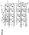
- Fig. 25 is a circuit diagram corresponding to a single unit group 32 upon the image capturing chip 2113.
- the representative rectangle surrounded by the dotted line shows the circuit that corresponds to a single pixel.
- each of the rectangles surrounded by a single dotted broken line corresponds to a single block 2131. It should be understood that at least some of the transistors explained in the following description correspond to the transistors 2105 of Fig. 23 .
- each of the unit groups 32 is formed from four of the blocks 2131.
- Reset transistors 2303 of the pixels included in the unit group 32 are turned ON and OFF by units of the blocks 2131.
- transfer transistors 2302 of the pixels included in the unit group 32 are also turned ON and OFF by units of the blocks 2131.
- reset wiring 2300-1 is provided for turning the four reset transistors 2303 corresponding to the upper left block 2131-1 ON and OFF, and also TX wiring 2307-1 is provided for supplying transfer pulses to the four transfer transistors 2302 corresponding to that same block 2131-1.
- reset wiring 2300-3 which is provided separately from the reset wiring 2300-1 described above, is provided for turning the four reset transistors 2303 corresponding to the lower left block 2131-3 ON and OFF.
- TX wiring 2307-3 which is provided separately from the TX wiring 2307-1 described above, is provided for supplying transfer pulses to turn the four transfer transistors 2302 corresponding to that same block 2131-3 ON and OFF.
- the sixteen PDs 2104 corresponding to each pixel are connected to the respectively corresponding transfer transistors 2302. And transfer pulses are supplied via the TX wiring for each of the blocks 2131 described above to the gates of the transfer transistors 2302.
- the drain of each transfer transistor 2302 is connected with the source of each corresponding reset transistor 2303, and also a so-called floating diffusion FD between the drain of the transfer transistor 2302 and the source of the reset transistor 2303 is connected with the gate of an amplifying transistor 2304.
- the drains of the reset transistors 2303 are connected in common to Vdd wiring 2310 to which power supply voltage is supplied. And reset pulses are supplied via reset wiring to the gates of the reset transistors 2303 of each of the blocks 2131 described above.
- the drains of the amplification transistors 2304 are connected in common to the Vdd wiring 2310, to which power supply voltage is supplied. Furthermore, the source of each of the amplification transistors 2304 is connected to the drain of the corresponding selection transistor 2305. And decoder wiring 2308, to which selection pulses are supplied, is connected to the gate of each of the selection transistors 2305. In this embodiment, such decoder wiring 2308 is provided independently for each of the sixteen selection transistors 2305. And the source of each of the selection transistors 2305 is connected to common output wiring 2309. A load current source 2311 supplies current to the output wiring 2309. In other words, the output wiring 2309 for the selection transistors 2305 is configured according to the source follower. It should be understood that the load current source 2311 could be provided upon the side of the image capturing chip 2113, or could be provided on the side of the signal processing chip 2111.
- reset wiring and TX wiring are provided in common for each of the four pixels that make up each of the blocks 2131.
- each reset pulse and each transfer pulse is applied simultaneously to all of the four pixels within the same block 2131. Accordingly, all of the pixels that make up one of the blocks 2131 start accumulation of electric charge at the same timing, and end accumulation of electric charge at the same timing.
- selection pulses being applied in sequence to the respective selection transistors 2305, the pixel signals corresponding to the accumulated electric charges are selectively outputted from the output wiring 2309.
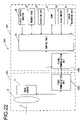
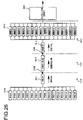
- Fig. 26 is a block diagram showing the functional structure of the image sensor 22.
- An analog multiplexer 2411 selects the sixteen PDs 2104 that make up a unit group 32 in order, and outputs the respective pixel signals to the output wiring 2309 that is provided to correspond to that unit group 32.
- This multiplexer 2411 is formed upon the image capturing chip 2113, along with the PDs 2104.
- the pixel signals outputted via the multiplexer 2411 are subjected to correlated double sampling (CDS) and analog/digital (A/D) conversion by a signal processing circuit 2412 that is formed upon the signal processing chip 2111, and that performs correlated double sampling (CDS) and analog/digital (A/D) conversion.
- CDS correlated double sampling
- A/D analog/digital
- the pixel signals that have thus been A/D converted are transferred to a demultiplexer 2413, and are stored in pixel memories 2414 corresponding to the respective pixels.
- the demultiplexer 2413 and the pixel memories 2414 are formed upon the memory chip 2112.
- the calculation circuit 2415 processes the pixel signals stored in the pixel memories 2414, it transfers them to a subsequent stage image processing unit.
- the calculation circuit 2415 may be provided upon the signal processing chip 2111, or may be provided upon the memory chip 2112. It should be understood that while, in Fig. 26 , the connections for a single unit group 32 are shown, actually these are provided for each of the unit groups 32, and operate in parallel. However, it will be acceptable for an individual calculation circuit 2415 not to be provided for each unit group 32; for example, it would also be acceptable to arrange for a single calculation circuit 2415 to perform sequential processing while referring to the values in the pixel memories 2414 corresponding to each unit group 32 in order.
- output wiring 2309 is provided corresponding to each of the unit groups 32. Since, in the image sensor 22, the image capturing chip 2113, the signal processing chip 2111, and the memory chip 2112 are laminated together, accordingly, by electrically connecting between the chips by using the bumps 2109 in this output wiring 2309, it is possible to route the wiring without making the chips larger in the surface direction.
- FIG. 1 is a block diagram showing the configuration of an image capturing device according to a first embodiment of the present invention.
- An image capturing device 10 is a lens-integrated type camera.
- the image capturing device 10 includes an image capturing optical system 21, an image sensor 22, a control unit 23, a liquid crystal monitor 24, a memory card 25, an actuation unit 26, a DRAM 27, a flash memory 28, and a recording unit 29.
- the image capturing optical system 21 is constituted by a plurality of lenses and forms a subject image upon an imaging surface of the image sensor 22. Note that in FIG. 1 , the image capturing optical system 21 is shown as a single lens.
- the image sensor 22 is an image sensor such as, for instance, CMOS or CCD, which picks up a subject image that is formed by the image capturing optical system 21 and outputs an imaging signal.
- the control unit 23 reads the control program from the flash memory 28 and executes it to thereby control each unit.
- This control program uses the DRAM 27, which is a volatile recording medium, as a workspace.
- the liquid crystal monitor 24 is a display device that has a liquid crystal panel.
- the control unit 23 allows the image sensor 22 to pick up a subject image repeatedly at a predetermined cycle (for instance, 1/60 second). Then, the image signal outputted from the image sensor 22 is subjected to various types of image processing to generate a so-called through-image or live view image, which is displayed on the liquid crystal monitor 24.
- On the liquid crystal monitor 24 is displayed, for instance, a setting screen, on which imaging parameters (imaging conditions) are to be set, as well as the through-image.
- the control unit 23 generates an image file as described below based on an imaging signal that is outputted from the image sensor 22 and records the image file in the memory card 25, which is a portable recording medium.
- the actuation unit 26 has various types of actuation members, such as push buttons, and outputs actuation signals to the control unit 23 in response to the actuation of the actuation members.
- the recording unit 29, which is constituted by, for instance, a microphone, converts environmental sound into audio signal and inputs the audio signal into the control unit 23. Note that the image file 40 does not have to be recorded in the memory card 25 which is a portable recording medium, but may be recorded in a hard disk drive which is a recording medium, not shown in the figures, built-in in the image capturing device 10.
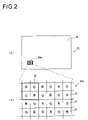
- FIG. 2(a) is a plan view schematically showing an imaging surface 30 of the image sensor 22.
- FIG. 2(b) is a plan view showing a partial region 30a of the imaging surface 30 in an enlarged scale.
- a large number of imaging pixels 31 are arranged two-dimensionally on the imaging surface 30.
- the imaging pixels 31 have each a color filter, not shown in the figures.
- the color filters are of the three types, red (R), green (G), and blue (B) filters.
- notations "R", "G", and "B” represent the types of the color filters that the imaging pixels 31 have.
- the imaging pixels 31 that have color filters of these types are arranged on the imaging surface 30 of the image sensor 22 according to a so-called Bayer array.
- the image sensor 22 is configured so as to enable its control for each of the unit group 32 made up from the four adjacent imaging pixels 31 in a 2 ⁇ 2 configuration, individually.
- This configuration it is possible to perform, when charge accumulation has started in, for instance, two mutually different unit groups 32, simultaneously, for one unit group 32, reading out of the charge, i.e., reading out of the light reception signals after 1/30 second from the start of the charge accumulation, while for the other unit group 32, reading out of the charge after 1/15 second after the start of the charge accumulation.
- the image sensor 22 can change timing at which charge accumulation is started and timing at which a light reception signal is read out for each unit group 32. That is, the image sensor 22 can change the frame rate upon image capturing a motion-image for each unit group 32.
- the image sensor 22 is configured to set exposure times, amplification factors, frame rates, and so on that are different for different unit groups 32, respectively. For instance, if a configuration is adopted in which a read out line, not shown in the figures, for reading out an imaging signal from a photoelectric conversion unit, not shown in the figures, of an imaging pixel 31 is provided at each unit group 32 such that an imaging signal can be read out from each unit group 32 independently of each other, different exposure times (shutter speeds) can be set for different unit groups 32, respectively.
- an amplification circuit not shown in the figures, for amplifying an imaging signal generated with a photoelectrically converted charge is provided at each unit group 32 independently of each other such that the amplification factors of amplification circuits can be controlled for each amplification circuit, the amplification factors (ISO sensitivity) can be changed for each unit group 32, separately.
- the number of the imaging pixels 31 that constitute the unit group 32 is not limited to the above-mentioned four pixels in a 2 ⁇ 2 configuration.
- the unit group 32 may have at least one imaging pixel 31 and conversely may have more than four imaging pixels 31.
- the imaging conditions that can be set separately for different unit groups 32 may be those conditions other than the above-described ones. For instance, if a configuration is adopted in which the image sensor 22 is provided with a liquid crystal panel that has sections (of which one section corresponds to one unit group 32) such that they can be controlled for each unit group 32 independently of each other and such configuration is used as a neutral density filter that can be turned on/off, it is possible to control brightness (i.e., aperture value) for each unit group 32.
- FIG. 3 is a schematic diagram showing a configuration of the image file according to the embodiment of the present invention.
- the image file 40 is constituted by two blocks, i.e., a header section 41 and a data section 42.
- the header section 41 is a block that is arranged on the head of the image file 40, in which file basic information section 43, a mask section 44, and an imaging information section 45 are stored in the order as described above.
- file basic information section 43 for instance, size and offset of each of the sections in the image file 40 (i.e., the header section 41, the data section 42, the mask section 44, the imaging information section 45 and so on) are recorded.
- mask section 44 imaging condition information, mask information and so on, which are described later, will be recorded.
- the imaging information section 45 for instance, information about image capturing, such as model name of the image capturing device 10 and information about the image capturing optical system 21 (for instance, information about the optical property, such as aberration) will be recorded.
- data section 42 which is a block placed behind the header section 41, is recorded image information, audio information, and the like.
- a still-image image capturing function A is a function to divide an image capture screen into a plurality of partial regions and set respective imaging conditions for the plurality of partial regions separately to allow image capturing of a still-image.
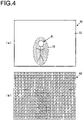
- FIG. 4(a) schematically shows an image capture screen 50 (an imaging range of the image sensor 22) and a subject 51.
- a procedure via which an image of the subject 51 that is shown in FIG. 4(a) is captured is explained.
- the control unit 23 takes an image of the subject 51 before main image capturing is performed.
- image capturing that is performed prior to main image capturing is referred to as preliminary image capturing.
- the preliminary image capturing may also be performed as image capturing for generating a live view image (so-called through-image).
- the control unit 23 executes predetermined image analysis processing on the image of the subject 51 acquired by preliminary image capturing (i.e., image in which the subject 51 comes out).
- the image analysis processing is a processing that detects a main subject part and a background part by using, for instance, a known subject detection technology (which is a technology that detects a range in which a predetermined subject is present by calculating an amount of characteristic).
- the image analysis processing achieves division of the image capture screen 50 into a main subject region 52 in which a main subject part is present and a background region 53 in which a background part is present.
- the main subject region 52 may have a shape along an outline of the subject 51. That is, the main subject region 52 may be set so as to exclude things other than the subject 51 as much as possible.
- the control unit 23 sets different imaging conditions for the unit groups 32 in the main subject region 52 and for the unit groups 32 in the background region 53. For instance, the control unit 23 may set a faster shutter speed for the former unit groups 32 than for the latter unit groups 32. With this setting, image blurring becomes difficult to occur in the main subject region 52 upon the main image capturing.
- the control unit 23 may set a relatively high ISO sensitivity or a relatively low shutter speed for the former unit groups 32. Also, the control unit 23 may set a relatively low ISO sensitivity or a relatively high shutter speed for the latter unit groups 32. With this setting, blocked up shadows in the main subject region 52 in a backlight state and blown out highlights of the background region 53 that receives a large amount of light can be prevented upon the main image capturing.
- the image analysis processing may be different from the processing that detects the above-mentioned main subject part and background part. For instance, it may be a processing that detects, among the whole image capture screen 50, a part having brightness equal to or higher than a predetermined value (too bright a part) and a part having brightness below a predetermined value (too dark a part). If the image analysis processing is such a processing, the control unit 23 may set a shutter speed and ISO sensitivity such that the unit groups 32 included in the former region can have an exposure value (Ev value) lower than that of the unit groups 32 in any other regions.
- Ev value exposure value
- control unit 23 sets a shutter speed and ISO sensitivity such that the unit groups 32 included in the latter region can have an exposure value (Ev value) higher than those for the unit groups 32 included in any other regions.
- Ev value exposure value
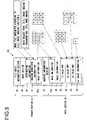
- FIG. 5 is a diagram schematically showing a configuration of the image file 40 that is generated in case image capturing is performed by using the still-image image capturing function A.
- the mask section 44 are recorded distinction information 60, imaging condition information 61 and mask information 62a in the above-described order.
- the distinction information 60 is information that indicates to the effect that this image file 40 is generated by using the still-image image capturing function A.
- the imaging condition information 61 is information that indicates what uses (objects, roles) the unit groups 32 have. For instance, in case that the image capture screen 50 ( FIG. 4(a) ) is divided into the main subject region 52 and the background region 53 as described above, each of the unit groups 32 belongs to either the main subject region 52 or the background region 53. That is, each unit group 32 have either a use of performing "still-image image capturing of a main subject part" or a use of performing "still-image image capturing of a background part".
- the imaging condition information 61 is information that indicates that upon generation of this image file 40, the unit groups 32 have two types of uses, one for "still-image image capturing of a main subject part" and the other for “still-image image capturing of a background part” and that represents respective unique numbers allotted to these uses. For instance, the number 1 is allotted to the use of "still-image image capturing of a main subject part” and the number 2 is allotted to the use of "still-image image capturing of a background part".
- the mask information 62a is information that represents uses (objects, roles) of the respective unit groups 32.
- the mask information 62a is defined as information "expressed in the form of a two-dimensional map in which numbers allotted to the imaging condition information 61 are plotted in accordance with the positions of the unit groups 32". That is, when the unit groups 32 that are arranged two-dimensionally are identified by a two-dimensional coordinate ((x, y)) with two integers x and y, the unit group 32 that is present at the position of ((x, y)) has a use that is expressed by the number that is present at the position of ((x, y)) of the mask information 62a.
- the unit group 32 arranged at the coordinate (3, 5) is given a use of "still-image image capturing of a main subject part". In other words, it is found that the unit group 32 arranged at the coordinate (3, 5) belongs to the main subject region 52.
- FIG. 4(b) An example of the mask information 62a that corresponds to the image capture screen 50 as shown in FIG. 4(a) is shown in FIG. 4(b) .
- "1" is stored at the positions of the unit groups 32 that belong to the main subject region 52.
- "2" is stored at the positions of the unit groups 32 that belong to the background region 53.
- the mask information 62b is the same information as the mask information 62a that is stored in the mask section 44.
- the reason that the same mask information 62a, 62b is stored in both the mask section 44 and the data section 42 is to make it easy to handle the image file 40.
- pieces of mask information 62a, 62b that are different from each other may be stored in the mask section 44 and in the data section 42, respectively, in the case of the image file 40 that is generated by another function. If, for instance, the mask information 62b is stored in the data section 42 and no mask information 62a is stored in the mask section 44 in the still-image image capturing function A, the structure of the image file 40 changes depending on the functions. This configuration makes it cumbersome and complicated to handle the image file 40. Accordingly, in this embodiment, the same pieces of mask information 62a, 62b are stored in both the mask section 44 and the data section 42 purposely to minimize a difference in structure of the image file 40 for each of the functions.
- either one of pieces of the mask information 62a, 62b may be omitted. If omitted, the size of the storage region occupied by the image file 40 can be reduced. Even if both the pieces of mask information 62a, 62b are recorded, it can be determined whether it is necessary to read in both the pieces of mask information 62a, 62b based on distinction information. Thus, if it is determined that one of them is unnecessary for a reproduction process and so on, then reading in of such one may be skipped to shorten file read-in time.
- the mask information 62a that is stored in the mask section 44 and the mask information 62b that is stored in the data section 42 are collectively called mask information 62.
- the image information 64 is information that is generated by recording imaging signals that are output from the image sensor 22 upon main image capturing before they are subjected to various types of image processing. This information is so-called RAW image data.
- the Tv value map 65 is information that is expressed in the form of a two-dimensional map generated by plotting Tv values representing shutter speeds that are set for respective unit groups 32 in accordance with the positions of the unit groups 32. For instance, the shutter speed that is set for the unit group 32 arranged at the coordinate (x, y) can be determined by checking the Tv value stored at the coordinate (x, y) in the Tv value map 65.
- the Sv value map 66 is information that is expressed in the form of a two-dimensional map generated by plotting Sv value representing ISO sensitivity that is set for each of the unit groups 32 in the same manner as that in the case of the Tv value map 65.
- the Bv value map 67 is information that is expressed in the form of a two-dimensional map generated by plotting luminance of the subject that is measured for each of the unit groups 32 upon main image capturing. That is, it is information that is expressed in the same form as the Tv value map 65 by plotting Bv values representing luminance of subject light incident in each of the unit groups 32.
- the Av value information 68 is information that represents aperture value upon main image capturing.
- Av values which are different from the Tv values, the Sv values, and the Bv values, are not present for each of the unit groups 32 separately. Therefore, unlike the Tv value, Sv value, and Bv value, only a single value is stored for the Av value, so that it is different from the information that is formed by two-dimensionally mapping a plurality of values.
- control unit 23 performs image capturing by using the still-image image capturing function A and thereby records in the memory card 25 the image file 40 in which the image information 64 that is generated by the image sensor 22 capable of setting respective imaging conditions for the unit groups 32 are correlated with data relating to the respective imaging conditions for the unit groups 32 (i.e., the imaging condition information 61, the mask information 62, the Tv value map 65, the Sv value map 66, and the Bv value map 67 and so on).
- the image information 64 is explained as being RAW image data. However, it need not be RAW image data but may be compressed (developed) image data.
- the motion-image image capturing function A is a function according to which the image capture screen is separated into a plurality of partial regions and imaging conditions are set therefor individually to perform imaging of a motion-image.
- the motion-image image capturing function A differs from the still-image image capturing function A in that the former performs image capturing of a motion-image but not a still-image.
- To perform image capturing of a motion-image instead of a still-image there is the possibility that "uses of respective unit groups 32" described regarding the still-image image capturing function A may be changed frame by frame.
- FIG. 6(a) schematically shows the image capture screen 50 (imaging range) of the image sensor 22 and the subject 51.
- the control unit 23 performs preliminary image capturing prior to main image capturing. Then, the control unit 23 executes predetermined image analysis processes on the image of the subject 51 (image in which the subject 51 comes out) acquired by the preliminary image capturing. By the image analysis processes, the image capture screen 50 is divided into a main subject region 52 in which a main subject part is present and a background region 53 in which a background part is present.
- the control unit 23 sets imaging conditions different from each other for the unit groups 32 in the main subject region 52 and for the unit groups 32 in the background region 53 and performs main image capturing for a first frame to generate image data.
- FIG. 6(b) An example of mask information 62 in this case is shown in FIG. 6(b) .
- the number "1" is allotted to the unit groups 32 belonging to the main subject region 52 and the number "2" is allotted to the unit groups 32 belonging to the background region 53.
- the control unit 23 performs image analysis processes on the first frame image data to detect a main subject part and a background part.
- the first frame image data is divided into the main subject region 52 and the background region 53 as shown in FIG. 6(c) .
- the control unit 23 sets imaging conditions that are different from each other for the unit groups 32 in the main subject region 52 and for the unit groups 32 in the background region 53 and performs a second frame main image capturing to generate image data.
- An example of the mask information 62 in this case is shown in FIG. 6(d) .
- these two pieces of mask information 62 may sometimes have contents different from each other in case, for instance, the subject 51 is moving or the user moves the image capturing device 10 because imaging is performed at different times (i.e., because of presence of time lag).
- the mask information 62 is dynamic information that varies with lapse of time. Therefore, in some of the unit groups 32, imaging conditions that are different from each other will be set at the times of the first frame main image capturing and the second frame main image capturing.
- the control unit 23 records, in the image file 40, the mask information 62b, the Tv value map 65, the Sv value map 66, the Bv value map 67, and the Av value information 68 for each frame as well as the image information 64 for each frame. Therefore, after image capturing, all the information upon image capturing can be acquired from the image file 40 and utilized effectively in reproduction of motion-images.
- control unit 23 repeatedly perform the above-mentioned processes until image capturing is completed (for instance, until a predetermined time is elapsed or until the user performs a predetermined imaging termination actuation).
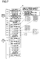
- FIG. 7 is a diagram schematically showing a configuration of the image file 40 that is generated when image capturing is performed by using the motion-image image capturing function A.
- FIG. 7 differences from image capturing by using the still-image image capturing function A as shown in FIG. 5 will be described in detail.
- the distinction information 60 indicates that the image file 40 is generated by using the motion-image image capturing function A.
- the imaging condition information 61 corresponds to the imaging condition information 61 upon imaging by using the still-image image capturing function A plus a frame rate. That is, the imaging condition information 61 is information that indicates that upon generation of the image file 40, the unit groups 32 have two types of uses, for instance, one for performing "motion-image image capturing of a main subject part at 60fps" and the other for performing "motion-image image capturing of a background part at 30fps" and that represents unique numbers allotted to the respective uses.
- the number "1” is allotted to the use of performing "motion-image image capturing of a main subject part at 60fps” and the number “2" is allotted to the use of performing "motion-image image capturing of a background part at 30fps”.
- the mask information 62a is information similar to that upon image capturing by using the above-mentioned still-image image capturing function A. However, upon the motion-image image capturing, the mask information 62, which is dynamic information that varies frame by frame, need be determined as to which frame is to be selected for recording its mask information 62 in the header section 41. In this embodiment, the mask information 62a representing respective imaging conditions that are set for the unit groups 32 at the first frame image capturing, that is, the mask information 62 that is shown as an example in FIG. 6(b) are recorded in the header section 41. This configuration is adopted to prevent handling of the image file 40 from becoming cumbersome and complicated as described in the explanation of the still-image image capturing function A.
- a block 70 for one frame quota is stored for each frame in the order of image capturing.
- a single block 70 includes the mask information 62, the image information 64, the Tv value map 65, the Sv value map 66, the Bv value map 67, and the Av value information 68.
- audio information 71 is stored together with the respective blocks 70 for the frames. To enable easy motion-image reproduction, the audio information 71 is divided into a plurality of pieces of information each containing information for one frame quota, each of which pieces is multiplexed with a corresponding block 70 before the divided and multiplexed pieces of information can be stored in the data section 42.
- multiplexing of the audio information 71 may be performed for every predetermined number of frame quotas instead of one frame quota.
- Each of the pieces of information in the block 70 is recorded frame by frame. Except for this, the image capturing by using the motion-image image capturing A is the same as the image capturing by using the still-image image capturing function A and further explanation is omitted.
- control unit 23 performs image capturing by using the motion-image image capturing function A to thereby record, in the memory card 25, the image file 40 in which the image information 64 that is generated by the image sensor 22 for which imaging conditions for each of the unit groups 32 can be set and data relating to imaging conditions (imaging condition information 61, mask information 62, Tv value map 65, Sv value map 66, and Bv value map 67 and so on) for each of the unit groups 32 are correlated with each other.
- Still-image image capturing function B (a plurality of still-images)
- the still-image image capturing function B is a function of simultaneously image capturing a plurality of still-images relating to the same subject under imaging conditions differing from each other by single image capturing operation.
- FIG. 8(a) schematically shows an imaging surface 30 of the image sensor 22.
- FIG. 8(b) is a schematic diagram showing a partial region 30b of the imaging surface 30 in an enlarged view.
- a plurality of unit groups 32 arranged in a two-dimensional array are further classified into a plurality of large groups 81.
- the unit groups 32 are classified such that unit groups 32 that belong to any one of the large groups 81 are arranged uniformly over all the imaging surface 80. For instance, in FIG.
- all the unit groups 32 are divided into blocks 82, each of which includes4 unit groups 32 arranged in a 2 ⁇ 2 configuration; in each block 82, the upper left unit group 32 is classified into a first large group 811, the lower left unit group 32 is classified into a second large group 812, the upper right unit group 32 is classified into a third large group 813, and the lower right unit group 32 is classified into a fourth large group 814.
- one schematically shown square represents a single unit group 32. The number described in the square represents the kind of the large group 81 to which that unit group 32 belongs.
- the control unit 23 Upon main image capturing, the control unit 23 sets respective imaging conditions that differ from each other for the unit groups 32 that belong to the first large group 811, the unit groups 32 that belong to the second large group 812, the unit groups 32 that belong to the third large group 813, and the unit groups 32 that belong to the fourth large group 814. For instance, the control unit 23 performs main image capturing with the shutter speed and ISO sensitivity set to values differing from each other. The control unit 23 records the image information acquired by performing image capturing in this manner in the image file 40. Here, the recorded image information is intended such that each pixel value is aggregated for each of the large groups 81 for further use as schematically shown in FIG. 8(c) .
- first image information 641 consisting of a number of pixel values, which number is 1/4 times the number of pixels of the image sensor 22, is obtained.
- second image information 642 is obtained, which consists of a number of pixel values, which number is 1/4 times the number of pixels of the image sensor 22 and in which the same subject 51 as that in the first image information 641 whose image has been captured under imaging conditions different from the above-mentioned first image information 641 comes out.
- third image information 643 and fourth image information 644 are obtained.
- the image information 64 in the image file 40 is an image obtained by arranging pixels output from respective imaging pixels 31 just according to the positions of the imaging pixels 31. That is, the processes for generating the above-mentioned four pieces of image information 641, 642, 643, and 644 are performed upon reproduction in which the image file 40 is read out from the memory card 25 or upon development. Furthermore, the image information 64 is not necessarily intended to be used only for generating the four pieces of image information 641, 642, 643, and 644. If the image information 64 is used (reproduced, etc.) as it is, without generation of a plurality of pieces of divided information, then, for instance, a checkerboard pattern comes out in the resultant image to make the image unnatural due to imaging conditions that differ from each of the adjacent unit groups 32, respectively.
- the way of classifying the unit groups 32 is not limited to four large groups but the unit groups 32 may be classified into any desired number of large groups 81 to enable simultaneous image capturing of any desired number of still-images.
- the layout of large groups 81 is not limited to classifying the unit groups 32 in a 2 ⁇ 2 configuration into different large groups 81, respectively, one by one.
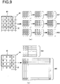
- FIGS. 9(a), and 9(b) some examples are shown in FIGS. 9(a), and 9(b) .
- all the unit groups 32 are separated into any of sets including nine unit groups in a 3 ⁇ 3 configuration and nine unit groups 32 included in each of the sets are allotted to first to ninth large groups 81, respectively.
- simultaneous image capturing of nine images 641 to 649 under mutually different imaging conditions can be achieved by a single imaging operation.
- FIG. 9(a) all the unit groups 32 are separated into any of sets including nine unit groups in a 3 ⁇ 3 configuration and nine unit groups 32 included in each of the sets are allotted to first to ninth large groups 81, respectively.
- all the unit groups 32 are separated any of sets including nine unit groups in a 3 ⁇ 3 configuration and in each of the sets, the unit group 32 at the upper left corner is allotted to the first large group 81, and four unit groups 32 in a 2 ⁇ 2 configuration at the lower right are allotted to the second large group 81.
- the rest four unit groups 32 are not used in image capturing.
- a single image capturing operation enables simultaneous imaging of two images 641, 642 under different imaging conditions, with the image 642 corresponding to the second large group 81 having a pixel number that is 4 times as large as the image 641 corresponding to the first large group 81. That is, a single imaging operation enables simultaneous imaging of two images 641, 642 under different imaging conditions, with the two images 641, 642 having mutually different pixel numbers.
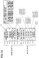
- FIG. 10 is a diagram schematically showing a configuration of the image file 40 that is generated upon imaging by using the still-image image capturing function B.
- the still-image image capturing function B differences of the still-image image capturing function B from the still-image image capturing function A will be described in detail.
- the distinction information 60 indicates that the image file 40 is generated by using the still-image image capturing function B.
- the imaging condition information 61 is information that indicates which use the unit group 32 has. In the case of the still-image image capturing function B, each unit group 32 has any one of uses, for instance, a use of "configuring the first image information 641", a use of "configuring the second image information 642", a use of "configuring the third image information 643", and a use of "configuring the fourth image information 644".
- the imaging condition information 61 is information that indicates that upon generating this image file 40, these four kinds of uses are present in the unit groups 32 and that represents unique numbers allotted to the respective uses. For instance, numbers 1 to 4 are allotted to uses of "configuring first to fourth image information 641 to 644", respectively.
- the mask information 62a is information represents a use of each of the unit groups 32 in the same manner as that in the case of the still-image image capturing function A. That is, the mask information 62a is "information expressed in the form of a two-dimensional map that is generated by plotting the numbers allotted to the imaging condition information 61 in accordance with the position of each unit group 32". For instance, when the number "1" is present at the coordinate (3, 5) of the mask information 62a, the unit group 32 at the coordinate (3, 5) belongs to the first large group 811, that is, constitutes the first image information 641.
- the large group 81 that has a number of "0" is a special large group 81 that represents a unit group 32 that is not used in image capturing. That is, in the mask information 62a the unit groups 32 to which the number "0" is allotted are not used in image capturing (i.e., no imaging signal is read out upon main image capturing) and no information about the unit groups 32 is included in the image information 64 that is recorded in the data section 42 (or dummy information which is ineffective is recorded as information about the unit groups 32).
- the number "0" will be allotted to the mask information 62a of the unit groups 32 to which "4" is allotted among the unit groups 32 shown in FIG. 8(b) .
- the structure of the data section 42 is the same as that of the data section 42 in image capturing by using the still-image image capturing function A. That is, in the data section 42 are stored the mask information 62b, the image information 64, the Tv value map 65, the Sv value map 66, the Bv value map 67, and the Av value information 68.
- the mask information 62b is the same information as the mask information 62a that is stored in the mask section 44.
- information that represents validity/invalidity of each of the unit groups 32 may be stored as the mask information 62b instead of the information that is the same as the mask information 62a of the mask section 44.
- a map generated by allotting a numerical value of "0" to the unit groups 32 that are not used in image capturing (i.e., from which no imaging signal is read out upon image capturing) and a numerical value of "1 " to the unit groups 32 that are used in image capturing (i.e., from which an imaging signal is read out upon image capturing) and arranging these numerical values in the form of a two-dimensional array may be stored in the data section 42 as the mask information 62b.
- image capturing by using a motion-image image capturing function B or a mixed image capturing function as described later.
- control unit 23 performs imaging by using the still-image image capturing function B to record, in the memory card 25, the image file 40 in which the image information 64 generated by the image sensor 22 for which imaging conditions can be set for each of the unit groups 32 separately is correlated with data relating to the imaging conditions (the imaging condition information 61, the mask information 62, the Tv value map 65, the Sv value map 66, the Bv value map 67, etc.) for each of the unit groups 32.
- Motion-image image capturing function B (a plurality of motion-images)
- the motion-image image capturing function B is a function that performs simultaneous imaging of motion-images relating to the same subject by a single imaging operation under mutually different imaging conditions.
- the motion-image image capturing function B differs from the still-image image capturing function B in that according to the former, motion-images are captured instead of still-images.
- the motion-image image capturing function B is a function of capturing motion-images, some unit groups 32 that are classified into a certain large group 81 are not classified into different large groups 81 frame by frame as in the motion-image image capturing function A.
- the motion-image image capturing function B will be explained based on the setting of frame rate.
- FIG. 11 is an illustrative diagram of the motion-image image capturing function B when frame rates are the same in all the large groups 81.
- the imaging conditions that differ for each of the large groups 81 means imaging conditions other than frame rate (for instance, shutter speed, ISO sensitivity, etc.). Even if the exposure time is different for each of the large groups 81, the frame rate, i.e., the period at which signals are read out, is the same. Hence in all the large groups 81, reading out of imaging signals is performed at a predetermined cycle T1 that corresponds to the frame rate.
- first image information 64 is generated at time t1, which is by a predetermined period T1 later than an image capturing start time t0.
- the image information 64 includes an image of a first frame in the first large group 81 (i.e., the frame indicated with #1 in FIG.
- FIG. 12 is an illustrative diagram of the motion-image image capturing function B when mutually different frame rates are set in all the large groups 81.
- a frame rate of 60fps is set for the first large group 811
- a frame rate of 50fps is set for the second large group 812
- a frame rate of 24fps is set for the third large group 813
- a frame rate of 25fps is set for the fourth large group 814.
- the control unit 23 records each frame based on the fastest frame rate as a standard. That is, the image information 64 is recorded at a predetermined cycle T2 (16.7 milliseconds) corresponding to 60fps. For instance, at time t11, which is by a predetermined period T2 later than the imaging start time t0, the image information 64 is generated based on imaging signals that are read out from the unit groups 32 belonging to the first large group 811 and stored in the image file 40. At time t11, no imaging signal is read out from the first frames in other large groups 812, 813, and 814, so that the image information 64 does not include such imaging signals. Note that in FIG. 12 , a symbol "X" indicates that no imaging signal is read out from a specified unit group 32 and the image information 64 does not include such an imaging signal.
- the control unit 23 reads out imaging signals from the unit groups 32 belonging to the first large group 811 and imaging signals from the unit groups 32 belonging to the second large group 812 and records the read out imaging signals in the image file 40. It reads out no imaging signal from the unit groups 32 belonging to the third large group 813 and the unit groups 32 belonging to the fourth large group 814, so that it records no imaging signal in the image file 40.
- the control unit 23 indicates that no imaging signal that corresponds to the specified unit group 32 is included in the image information 64 based on the mask information 62b that is recorded for each frame. Specific structure of the mask information 62b will be described hereinbelow.
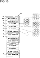
- FIG. 13 is a diagram schematically showing the structure of the image file 40 that is generated upon image capturing by using the motion-image image capturing function B.
- differences of the motion-image image capturing function B from the motion-image image capturing function A as shown in FIG. 7 and the still-image image capturing function B as shown in FIG. 10 are described in detail.
- the distinction information 60 indicates that the image file 40 is generated by using the motion-image image capturing function B.
- the imaging condition information 61 is information as to which uses the unit groups 32 have.
- the imaging condition information 61 in the motion-image image capturing function B corresponds to information obtained by adding frame rate to the imaging condition information 61 in the still-image image capturing function B.
- the imaging condition information 61 is information that indicates that upon generating the image file 40, the unit groups 32 have, for instance, four kinds of uses, i.e., a use of "configuring the first image information 641 which is a motion-image at 60fps", a use of “configuring the second image information 642, which is a motion-image at 50fps", a use of “configuring the third image information 643, which is a motion-image at 24fps", and a use of "configuring the fourth image information 644, which is a motion-image at 25fps" and that represents unique numbers allotted to these uses. For instance, the numbers 1 to 4 are allotted to the uses of "configuring the first to the fourth pieces of image information 641 to 644", respectively.
- the mask information 62a in the motion-image image capturing function B is information that represents respective uses of the unit groups 32 in the same manner as that in the still-image image capturing function B. That is, the mask information 62a is "information expressed in the form of a two-dimensional map generated by plotting numbers allotted to the imaging condition information 61 in accordance with the positions of the respective unit groups 32". For instance, when the number "1" is present at the coordinate (3, 5) of the mask information 62a, it is determined that the unit group 32 at the coordinate (3, 5) belongs to the first large group 811, that is, it constitutes the first image information 641.
- the configuration of the data section 42 is the same as the motion-image image capturing function A. That is, in the data section 42, the block 70 of one frame quota is stored for each frame.
- One block 70 includes mask information 62b, image information 64, a Tv value map 65, a Sv value map 66, a Bv value map 67, and Av value information 68.
- audio information 71 together with the block 70 for each frame is stored.
- the control unit 23 sets the numerical value of the mask information 62 that corresponds to the specific unit group 32 to "0".
- the numerical value of the mask information 62b is set to "0"
- no valid values are recorded for information other than the image information 64, i.e., the Tv value in the Tv value map 65, the Sv value in the Sv value map 66, and the Sv value in the Bv value map 67.
- a configuration may be adopted in which the imaging signal in a preceding frame of the unit group 32 is recorded in the image information 64. Also, the values of a preceding frame may be recorded regarding the Tv value in the Tv value map 65, the Sv value in the Sv value map 66, and the Sv value in the Bv value map 67.
- control unit 23 records in the memory card 25 the image file 40 in which the image information 64 generated by the image sensor 22 for which imaging conditions can be set for each of the unit groups 32 is correlated with data regarding the imaging conditions for each of the unit groups 32 (the imaging condition information 61, the mask information 62, the Tv value map 65, the Sv value map 66, and the Bv value map 67, etc.) by performing image capturing by using the motion-image image capturing function B.
- Mixed image capturing function is a function obtained by combining the still-image image capturing function B and the motion-image image capturing function B, which allows simultaneous image capturing of a still-image and a motion-image relating to the same subject under mutually different imaging conditions by a single imaging operation.
- the control unit 23 further classifies a plurality of unit groups 32 that is arranged in a two-dimensional array into a plurality of large groups 81 in a manner similar to those of the still-image image capturing function B and the motion-image image capturing function B.
- the control unit 23 performs motion-image image capturing for some of the large groups 81 in the same manner as that of the motion-image image capturing function B.
- the control unit 23 performs still-image image capturing in the same manner as that of the still-image image capturing function B during its motion-image image capturing by using the other large groups 81.
- This still-image image capturing may be performed, for instance, at a constant cycle repeatedly (automatic image capturing) or may be performed in response to a specified actuation by the user (manual image capturing).
- FIG. 14 is an illustrative diagram for illustrating the mixed image capturing function.
- four large groups 811 to 814 are assumed to be present. Among them, 60fps motion-image image capturing is performed for the first large group 811, 50fps motion-image image capturing is performed for the second large group 812, and still-image image capturing is performed in the third and fourth large groups 813, 814.
- the control unit 23 records each frame based on the fastest frame rate (for instance, 60fps) as a standard similarly to the motion-image image capturing function B. While the still-image image capturing is not performed, always no imaging signal is read out from the unit groups 32 belonging to the third and fourth large groups 813, 814. That is, the image information 64 that is recorded frame by frame does not contain imaging signals of the unit groups 32 belonging to the third and fourth large groups 813, 814 that correspond to still-images.
- the fastest frame rate for instance, 60fps
- control unit 23 When the control unit 23 performs still-image image capturing, it causes, at timing at which still-image image capturing is completed (i.e., at timing at which imaging signals are read out from the unit groups 32 that belong to the third and fourth large groups 813, 814), the image information 64 that corresponds to a frame immediately after the completion of the still-image image capturing to contain the imaging signals that have been read out as a result of that still-image image capturing.
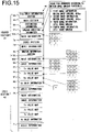
- FIG. 15 is a diagram schematically showing the structure of the image file 40 that is generated when imaging is performed by using a mixed image capturing function.
- the mixed image capturing function from the motion-image image capturing function B as shown in FIG. 13 are described in detail.
- the distinction information 60 indicates that the image file 40 is generated by using the mixed image capturing function.
- the imaging condition information 61 is information that indicates what uses the unit groups 32 have. In the case of the mixed image capturing function, the imaging condition information 61 is information that indicates that, for instance, upon generating the image file 40, the unit groups 32 have four kinds of uses, i.e., a use of "configuring first image information 641, which is a motion-image of 60fps", a use of "configuring second image information 642, which is a motion-image of 30fps", a use of "configuring third image information 643, which is a still-image", and a use of "configuring fourth image information 644, which is a still-image” and that represents unique numbers allotted to these uses, respectively. For instance, numbers 1 to 4 are allotted to the uses of "configuring the first to fourth pieces of image information 641 to 644".
- the mask information 62a in the case of the mixed image capturing function is information that indicates respective uses of the unit groups 32 similarly to the case of the motion-image image capturing function B. That is, the mask information 62a is "information expressed in the form of a two-dimensional map obtained by plotting the numbers allotted to the imaging condition information 61 in accordance with the positions of the unit groups 32". For instance, when the number of "1" is present at the coordinate (3, 5) of the mask information 62a, the unit group 32 at the coordinate (3, 5) belongs to the first large group 811, that is, constitutes the first image information 641.
- the header section 41 additionally contains an index section 73.
- index information 74 that indicates which block 70 among a plurality of blocks 70 (corresponding to a plurality of frames, respectively) has stored therein a still-image.
- the index information 74 includes, for instance, one or a plurality of pieces of information (corresponding to the number of times of still-image image capturing) such as information "third image information 643 contained in the fifth frame image information 64 includes a still-image".
- the index section 73 is provided so that a still-image can be quickly searched from a plurality of blocks 70.
- the index information 74 may be information other than that identifies the recording position of the still-image based on the number of frames. For instance, the recording position of the still-image can be identified based on the reproduction time of the motion-image. In this case, the index information 74 is, for instance, information indicating that "the third image information 643 in the image information 64 at time of 3 minutes 15 seconds contains a still-image".
- the control unit 23 adds the frame number or the time of still-image image capturing to the index section 73 as the index information 74 each time the still-image image capturing is performed while image capturing is being performed by using the mixed image capturing function.
- the control unit 23 may be configured to store the index section 73 in the DRAM 27 temporarily and transfer the information in the DRAM 27 to the index section 73 of the image file 40 in the memory card 25 when the mixed image capturing function is terminated instead of directly adding the index information 74 to the index section 73 of the image file 40 within the memory card 25.
- the configuration of the data section 42 is the same as that in the case of the motion-image image capturing function B. That is, in the data section 42, a block 70 for one frame quota is stored for each frame in the order of image capturing.
- a single block 70 is constituted by the mask information 62, the image information 64, the Sv value map 66, the Tv value map 65, the Bv value map 67, and the Av value information 68.
- the audio information 71 together with the block 70 for each frame is stored.
- control unit 23 performs image capturing by using the mixed image capturing function to record in the memory card 25 the image file 40 in which the image information 64 that is generated by the image sensor 22 for which imaging conditions can be set separately for each of the unit groups 32 is correlated with data (the imaging condition information 61, the mask information 62, the Tv value map 65, the Sv value map 66, and the Bv value map 67, etc.) relating to the imaging conditions for each of the unit groups 32.
- data the imaging condition information 61, the mask information 62, the Tv value map 65, the Sv value map 66, and the Bv value map 67, etc.
- the reproduction process of an image is a process for generating an image of a subject from the image files 40 that are recorded in the memory card 25 by using the above-described various types of image capturing functions.
- the control unit 23 may for instance, display the generated image on the liquid crystal monitor 24 or may record the generated image in the memory card 25 as a file separate from the image file 40.
- the control unit 23 opens the image file 40 ( FIG. 5 , FIG. 7 , FIG. 10 , FIG. 13 , and FIG. 15 ) and reads out at first the file basic information section 43. This enables the offset and size of the mask section 44, the data section 42, etc. of the image file 40 to be found. Then, the control unit 23 reads out the distinction information 60 from the mask section 44 of the image file 40. As a result, the control unit 23 can recognize which image capturing function is used for generating the image file 40. Subsequent processing may differ for different image capturing functions. Accordingly, reproduction process of an image is explained for each of the above-mentioned image capturing functions.
- the control unit 23 When the control unit 23 recognizes that the image file 40 is a file that is generated by using the still-image image capturing function A as shown in FIG. 5 , it reads out the imaging condition information 61 and the mask information 62a from the mask section 44. As a result, the control unit 23 can recognize which range (which unit groups 32) among the whole image capture screen is a main subject part or a background part and change the construction of the image based on the main subject part and the background part. For instance, the main subject part is subjected to an edge enhancement process to make the image sharper and the background part is subjected to an airbrushing or blurring process to enhance the main subject part.
- the control unit 23 reads out the image information 64, the Tv value map 65, the Sv value map 66, the Bv value map 67, and the Av value information 68 from the data section 42. Then, the control unit 23 executes a so-called development process on the image information 64 based on the Tv value map 65, the Sv value map 66, the Bv value map 67, and the Av value information 68 that are thus read out.
- the image processing section 23 executes, for instance, a well-known demosaicing process on the image information 64 having no color information to generate an image having color information. Also, the control unit 23 performs image processing such as adjustment of color, brightness, etc., noise reduction, etc.
- control unit 23 reduces noises more intensely when Sv values are larger.
- the control unit 23 can, for instance, display the image thus generated on the liquid crystal monitor 24 or record it in the memory card 25.
- the control unit 23 reads out the imaging condition information 61 and the mask information 62a recorded in the mask section 44 prior to reading out the information recorded in the data section 42, such as image information 64, etc. This can minimize the seek time that will be generated upon reproduction process since the mask section 44 is recorded before the data section 42.
- control unit 23 may be configured to read out the mask information 62b instead of the mask information 62a from the data section 42.
- control unit 23 When the control unit 23 recognizes that the image file 40 is a file generated by using the motion-image image capturing function A as shown in FIG. 7 , it reads out the mask information 62a from the mask section 44. The control unit 23 determines which range (which unit groups 32) among the whole image capture screen is a main subject part or a background part. Then, the control unit 23 reads out the imaging condition information 61 from the mask section 44. As a result, the control unit 23 can recognize frame rates of the main subject part and background part.
- control unit 23 reads out the image information 64, the data section 42, the Tv value map 65, the Sv value map 66, the Bv value map 67, and the Av value information 68 from a head or first block 70 of the data section 42 and subsequent blocks 70 in order and generates each frame that constitutes a motion-image based thereon.
- the control unit 23 Upon generating each of the frames, the control unit 23 reads out from the block 70 at first the mask information 62b. Then, it determines which range (which unit groups 32) in the frame is a main subject part or a background part. Thereafter, the control unit 23 executes different image processes on the main subject part and on the background part as explained with respect to the still-image image capturing function A.
- the control unit 23 reads out the mask information 62b prior to the information recorded in the block 70, such as image information 64, etc. Since the mask information 62b is recorded before the image information 64, etc., the seek time that will occur upon reproduction process can be minimized.
- control unit 23 may be configured so as not to read out the mask information 62a from the mask section 44.
- Still-image image capturing function B (a plurality of still-images)
- control unit 23 When the control unit 23 recognizes that the image file 40 is a file that is generated by using the still-image image capturing function B as shown in FIG. 10 , it reads out the imaging condition information 61 and the mask information 62a from the mask section 44. This allows the control unit 23 to determine how many kinds of still-images are captured simultaneously and which unit groups 32 constitutes any one of still-images. That is, it determines how many large groups 81 are present and to which large group each of the unit groups 32 belongs.
- the control unit 23 reads out the image information 64, the Tv value map 65, the Sv value map 66, the Bv value map 67, and the Av value information 68 from the data section 42. Then, the control unit 23 executes a so-called development process on the image information 64 for each large group 81 separately based on the Tv value map 65, the Sv value map 66, the Bv value map 67, and the Av value information 68 to generate a still-image. As a result, a plurality of still-images (for instance, four still-images) is generated.
- the control unit 23, for instance, displays the images generated as described above on the liquid crystal monitor 24 or records them in the memory card 25.
- the control unit 23 reads out the imaging condition information 61 and the mask information 62a recorded in the mask section 44 prior to the information recorded in the data section 42, such as the image information 64, etc. Since the mask section 44 is recorded before the data section 42, the seek time that will occur upon reproduction process can be minimized.
- the mask information 62b which is the same information as the mask information 62a stored in the header section 41 is stored in the data section 42. Accordingly, the mask information 62b may be read out from the data section 42 instead of the mask information 62a.
- Motion-image image capturing function B (a plurality of motion-images)
- control unit 23 When the control unit 23 recognizes that the image file 40 is a file that is generated by using the motion-image image capturing function B as shown in FIG. 13 , it reads out the mask information 62a and the imaging condition information 61 from the mask section 44. This allows the control unit 23 to determine how many kinds of motion-images are captured simultaneously, which unit groups 32 constitute any one of motion-images, and the frame rate of each motion-image. That is, it determines how many large groups 81 are present, which large group 81 each of the unit groups 32 belongs to, and the frame rate at which each of the large groups 81 is imaged.
- control unit 23 reads out the image information 64, the Tv value map 65, the Sv value map 66, the Bv value map 67, and the Av value information 68 from the head and subsequent blocks 70 in the data section 42 in order and generates each of the frame that constitute each of the motion-images based thereon.
- the control unit 23 For generating each of the frames, the control unit 23 at first reads out the mask information 62b from the block 70. Then the control unit 23 determines which large group 81 the pixel signal contained in the image information 64 in the block 70 corresponds to. Thereafter, the control unit 23 generates a frame that corresponds to each of the large groups 81. However, it generates no frame for a large group 81 if no pixel signal corresponding to this large group 81 is contained in the image information 64 in the block 70. The control unit 23, for instance, displays the motion-image constituted by the frames that are generated as described above on the liquid crystal monitor 24 or records it in the memory card 25.
- the control unit 23 reads out the mask information 62a, 62b prior to the information recorded in the block 70, such as the image information 64, etc. Since the mask information 62a, 62b is recorded before the image information 64, etc, the seek time that will occur upon the reproduction process can be minimized.
- control unit 23 may be configured so as not to read out mask the information 62a from the mask section 44.
- control unit 23 When the control unit 23 recognizes that the image file 40 is a file that is generated by using the mixed image capturing function as shown in FIG. 15 , it reads out the mask information 62a and the imaging condition information 61 from the mask section 44. This allows the control unit 23 to determine how many kinds of motion-images and how many kinds of still-images are captured simultaneously, which unit groups 32 constitutes any one of still-images and any one of motion-images, and the frame rate of each motion-image.
- control unit 23 determines how many large groups 81 are present, whether each of the large groups 81 is a still-image or a motion-image, the frame rate of each of the unit groups 32 if the large group 81 is a motion-image, and which large group 81 any one of the unit groups 32 belongs to. Then, the control unit 23 reads the image information 64, the Tv value map 65, the Sv value map 66, the Bv value map 67, and the Av value information 68 from the head and subsequent blocks 70 in the data section 42 in order and generates, based thereon, each of the frames that constitute each of the motion-images and each of the still-images.
- the control unit 23 For generating each of the frames of a motion-image or a still-image, the control unit 23 at first reads out the mask information 62b from the block 70. Then, it determines which large group 81 the pixel signal contained in the image information 64 in the block 70 corresponds to. Thereafter, the control unit 23 generates a frame or a still-image that corresponds to each of the large groups 81. However, it generates neither frame nor still-image for a large group 81 if no pixel signal corresponding to this large group 81 is contained in their image information 64 in the block 70.
- the control unit 23 reads out the mask information 62a, 62b prior to the information recorded in the block 70, such as the image information 64, etc. Since the mask information 62a, 62b is recorded before the image information 64, etc, the seek time that will occur upon the reproduction process can be minimized.
- control unit 23 may be configured to read out no mask information 62a from the mask section 44.
- the reproduction process of images is a process by which an image of a subject is generated based on the image file 40 that is recorded in the memory card 25 by one of the above-mentioned various types of image capturing functions. However, it may be a process by which a still-image and/or a motion-image is generated based on the image file 40 before it can be recorded in the memory card 25.
- the control unit 23 may be configured to perform a compression process after the still-image and/or motion-image is generated.
- a configuration may be adopted in which an electronic apparatus that is different from the image capturing device 10 (hereafter, referred to as a reproduction device) executes the above-mentioned reproduction process.
- a configuration may be adopted in which when the memory card 25 is removed from the image capturing device 10 and attached to a reproduction device in a personal computer (PC), the reproduction device reads out the image file 40 from the memory card 25 and executes the above-mentioned reproduction process to reproduce an image.
- data communication such as wireless communication
- the image capturing device according to the above-mentioned first embodiment provides the following operations and advantageous effects.
- An image capturing device has a configuration similar to that of the image capturing device 10 according to the first embodiment.
- the methods for recording the image file 40 according to the still-image image capturing function B, the motion-image image capturing function B, and the mixed image capturing function are different from those in the first embodiment.
- this feature is described in detail.
- the still-image image capturing function B, the motion-image image capturing function B, and the mixed image capturing function are each a function by which a plurality of still-images and/or a plurality of motion-images relating to the same subject are captured simultaneously by a single image capturing operation.
- the control unit 23 is configured so as to divide the plurality of still-images and/or the plurality of motion-images thus captured into a plurality of image files 40 and record them separately instead of recording them into a single image file 40. On this occasion, the control unit 23 records the separately recorded image files 40 in correlation with each other.
- the divided files are recorded separately for convenience's sake, the information indicating that the plurality of image files 40 have been acquired by a single imaging operation is not impaired, similarly to the first embodiment.
- the plurality of image files 40 can be handled later under recognition that they have been acquired by a single image capturing operation similarly to the case in the first embodiment.
- FIG. 16 is a diagram schematically showing a directory structure of the memory card 25.
- a root directory 90 of the memory card 25 has a DCIM directory 91a.
- the DCIM directory 91a has therein a subdirectory 91b for storing images.
- the control unit 23 For each single image capturing operation by using the still-image image capturing function B, the motion-image image capturing function B, or the mixed image capturing function, the control unit 23 generates a single imaging set directory 92 in this subdirectory 91b. That is, one imaging set directory 92 corresponds to one image capturing operation.
- one administration data file 93 and subdirectories 94 for respective uses of the unit group 32 are generated. For instance, if a unit groups 32 have four uses, four subdirectories 94 are generated. For each of the subdirectories 94, at least one image file 40 corresponding to a use of the unit group 32 is generated. For instance, if the use of the unit group 32 is the motion-image image capturing, only one motion-image file 401 is recorded in the subdirectory 94 corresponding to this use. On the other hand, if the use of the unit group 32 is the still-image image capturing, a still-image file 402 is recorded in the subdirectory 94 a number of times that corresponds to the number of times of image capturing operation. Note that in the case of the still-image image capturing function B, only one still-image file 402 is recorded for each of the uses by a single image capturing operation, so that one still-image file 402 is recorded in each subdirectory 94.
- FIG. 17(a) is a diagram schematically showing the structure of the administration data file 93.
- the administration data file 93 is a file in which information that correlates the image files 40 recorded in the subdirectories 94 with each other and includes a file basic information section 43, a mask section 44, an index section 73, and an imaging information section 45.
- the file basic information section 43, the mask section 44, and the imaging information section 45 are the same as those sections having the same names in the image file 40 that are explained in FIG. 15 , etc.
- layout information 96 that indicates which use of the unit group 32 each of the subdirectories 94 corresponds to, is recorded.
- FIG. 17(b) is a diagram schematically showing the structure of the still-image file 402 that is recorded in the subdirectory 94.
- the still-image file 402 are recorded mask information 62b, image information 64, a Tv value map 65, a Sv value map 66, a Bv value map 67, and Av value information 68. Since the Av value information 68 is similar to that explained in FIG. 10 and explanation thereof is omitted.
- the mask information 62b, the image information 64, the Tv value map 65, the Sv value map 66, and the Bv value map 67 are each information that is obtained by extracting only values corresponding to one of the large groups 81 from the information having the same name as explained in FIG. 10 and arranging the extracted values in a two-dimensional array.
- the mask information 62b is "information that contains numbers allotted to imaging condition information 61 expressed in the form of a two-dimensional map in accordance with the positions of the unit groups 32".
- the number of values contained in the mask information 62b is the same as the number of the unit groups 32.
- the mask information 62b in the still-image file 402 is information that is prepared by extracting from all the values only those values that correspond to the large group 81, which in turn corresponds to this subdirectory 94, and expressing the extracted values in the form of a two-dimensional map.
- the image information 64, the Tv value map 65, the Sv value map 66, and the Bv value map 67 are similarly prepared and one still-image file 402 contains only those values corresponding to one large group 81.
- FIG. 18 is a diagram schematically showing the structure of the motion-image file 401 that is recorded in the subdirectory 94.
- the motion-image file 401 is stored one frame quota block 70 for each of the frames in order of image capturing.
- a single block 70 includes mask information 62b, image information 64, ae Tv value map 65, a Sv value map 66, a Bv value map 67, and Av value information 68.
- the motion-image file 401 has stored therein the block 70 for each frame together with audio information 71. Since the Av value information 68 is similar to that explained in FIG. 13 and explanation thereof is omitted.
- the mask information 62b, the image information 64, the Tv value map 65, the Sv value map 66, and the Bv value map 67 are each information that is obtained by extracting only values corresponding to one large group 81 from the information having the same name as explained in FIG. 13 and arranging the extracted values in a two-dimensional array. This is the same as in the case of the above-mentioned still image file 402 and explanation thereof is omitted.
- the control unit 23 records, in the memory card 25, the image information 64 that is generated by the image sensor 22 for which imaging conditions can be set for each of the unit groups 32 separately in correlation with data relating to the imaging conditions (the imaging condition information 61, the mask information 62, the Tv value map 65, the Sv value map 66, the Bv value map 67, etc.) for each of the unit groups 32.
- the administration data file 93, the motion image file 401, and the still image file 402 are correlated with each other via the layout information 96 in the administration data file 93 although they do not form a single image file 40.
- the image capturing device according to the second embodiment provides the similar operation and advantageous effects as those of the image capturing device according to the first embodiment.
- the first image information 641 and the second image information 642 have been explained that they are generated when reproducing the image file 40. However, they may be recorded in the image file 40 in advance. In other words, the motion-image and the still-image, which are recorded in different subdirectories 94 as different files for each of the large groups 81 separately in the second embodiment, may be recorded in a single image file 40. In this case, data for one frame quota that is recorded in the image file 40 corresponds to one large group 81.
- first motion-image and second motion-image that are recorded in two files, separately, according to the second embodiment are recorded in a single image file 40.
- first motion-image and second motion-image that are recorded in two files, separately, according to the second embodiment are recorded in a single image file 40.
- data relating to the first frame, second frame, third frame, ... , respectively, of the first motion-image are recorded in chronological order, and subsequently data relating to the first frame, second frame, third frame, ..., respectively, of the second motion-image are recorded in chronological order.
- the load of the reproduction process can be reduced.
- a recording method may be adopted in which data relating to each frame of the first motion-image and data relating to each frame of the second motion-image are recorded in chronological order with respect to each of the frames. That is, each of the frames of each of two motion-images may be recorded in the form of an array in chronological order of image capturing, such as an array of "the first frame of the first motion-image, the first frame of the second motion-image, the second frame of the first motion-image ". This enables the recording process to be performed at a reduced load.
- FIG. 19 is an illustrative diagram for illustrating Variation Example 2.
- the unit groups 32 are classified into four large groups 81 in the same manner as in FIG. 8(b) .
- the image information 64 that will be generated by the control unit 23 afterward is not formed by arranging imaging signals according to the array of the unit groups 32.
- the image information 64 is generated by aggregating imaging signals for each large group 81 and then interlinks them. For instance, when the image information 64 is separated into four regions in a 2x2 construction, imaging signals from the unit groups 32 belonging to the first large group 81 are aggregated in the upper left region. In the lower left region, imaging signals from the unit groups 32 belonging to the second large group 81 are aggregated. Further, in the upper right region, imaging signals from the unit groups 32 belonging to the third large group 81 are aggregated. In the lower right region, imaging signals from the unit groups 32 belonging to the fourth large group 81 are aggregated.
- the array of the image information 64 may be changed by a method other than this. That is, as long as the array in the image information 64 and the array in other information relating to other imaging conditions (mask information 62, etc.) correspond to each other in the image file 40, any types of arrays may be employed.
- the use of the unit group 32 may be changed frame by frame. For instance, it is configured such that as shown in FIG. 20 , the unit groups 32 are classified into the first to fourth large groups 81 for odd number frames so that the image information 64 containing four pieces of the image information 641, 642, 643, 644 with different imaging conditions can be obtained. For even number frames, the unit groups 32 are classified into the fifth large group 81 only so that only the single image information 64 can be obtained. That is, a configuration may be adopted in which a plurality of images having different imaging conditions with a relatively small number of pixels and a single image with a relatively large number of pixels are captured in a time shared fashion. Variation Example 3 may be applied to Variation Example 1 or to Variation Example 2 described above.
- a configuration may be adopted in which a single unit group 32 has a plurality of uses.
- a configuration may be adopted in which as shown in FIG. 21 , the unit groups 32 are classified into the first to fourth large groups 81, respectively and also all the unit groups 32 are classified into the fifth large group 81.
- reproduction (development, etc.) of the image file 40 is performed according to the former classification, the image information 64 that contain the four pieces of the image information 641, 642, 643, 644 can be obtained.
- reproduction (development, etc.) of the image file 40 is performed according to the latter classification, the single image information 64 with a larger number of pixels can be obtained.
- the unit group 32 for which the number "0" is allotted on the mask information 62, is not used in imaging and the image information 64 recorded in the data section 42 contains no information relating to that unit group 32.
- the image information 64 recorded in the data section 42 contains no information relating to that unit group 32.
- a configuration may be adopted in which the number "0" has the same meaning as that in the case of the still-image image capturing function B.
- a configuration may be adopted in which the number "0" in the mask information 62 in the header section 41 indicates that the unit group 32, for which the number "0" is allotted, is not used in image capturing. For instance, when, in the case of the still-image image capturing function B and the motion-image image capturing function B, the whole image capture screen is separated into sets of four unit groups 32 in a 2 ⁇ 2 configuration, different uses are allotted to different unit groups 32, respectively, and if the number of the unit groups 32 in the vertical direction (row number) is odd, one row is left as the balance. In such a case, a configuration may be adopted in which the one row left as the balance is not used in imaging and the number of "0" is allotted to the one row in the mask information 62 that is recorded in the header section 41.
- the structure of the image file 40 may be different from those of the above-mentioned embodiments.
- the information relating to the imaging conditions that is recorded in the image file 40 may be different from the information that is explained in the first embodiment, etc. For instance, recording of some information such as the Sv value map 66 or the like may be omitted. On the contrary, information other than the above-mentioned one may further be added. Furthermore, the mode of recording may be different from those in the above-mentioned embodiments.
- the Av value information 68 may be recorded as an Av value map generated by arranging Av values in a two-dimensional array for each of the unit groups 32 in the same manner as that in Tv values, Sv values, etc.
- the image capturing device which is a single electronic apparatus that includes the image sensor 22 and the control unit 23, has been explained.
- the present invention is not limited to these embodiments.
- the present invention may be applied to an electronic apparatus that controls the image sensor 22 provided as an external device.
- a mode in which an image capturing unit 1001 provided with the image sensor 22 is controlled through an external apparatus, is explained in detail.
- FIG. 22 is a block diagram schematically showing a configuration of an image capturing system according to Variation Example 7.
- the image capturing system 1000 shown in FIG. 22 includes the image capturing unit 1001 and an electronic apparatus 1002.
- the image capturing unit 1001 includes the image capturing optical system 21 and the image sensor 22 that are explained in the first embodiment and further a first communication unit 1003.
- the electronic apparatus 1002 includes the control unit 23, the liquid crystal monitor 24, the memory card 25, the actuation unit 26, the DRAM 27, the flash memory 28, and the recording unit 29 that have been explained in the first embodiment and further a second communication unit 1004.
- the first communication unit 1003 and the second communication unit 1004 are capable of performing bidirectional data communication by using, for instance, a well-known wireless communication technology and an optical communication technology, etc.
- a configuration may be adopted in which the image capturing unit 1001 and the electronic apparatus 1002 perform bidirectional data communication via wire-line connection such as cable, etc. to enable bidirectional data communication between the first communication unit 1003 and the second communication unit 1004.
- control unit 23 controls the image sensor 22 by data communication through the second communication unit 1004 and the first communication unit 1003. For instance, by transmitting and receiving predetermined control data to and from the image capturing unit 1001, the control unit 23 sets imaging conditions that differ for each of the unit groups 32 or reads out an imaging signal from each of the unit groups 32.
- control on each of the unit groups 32 is performed by the control unit 23.
- the electronic apparatus 1002 is provided with no image sensor 22.
- the image sensor 22 image capturing unit 1001 that is provided outside of the electronic apparatus 1002
- the same control as that in the first embodiment can be obtained. That is, the present invention can be applied to an electronic apparatus that has no image sensor 22.
- the image information 64 may be compressed by a well-known reversible compression technology before it is recorded.
- the image information 64 may be recorded in the form of difference values with respect to adjacent pixels. For instance, a configuration may be adopted in which at a position, at which the pixel value (imaging signal) of a specified pixel is recorded, is recorded a difference value between the specified pixel and its left adjacent pixel. Alternatively, a difference value from an average pixel value of all the pixels in a predetermined region may be recorded or a difference value from an average pixel value of all the pixels may be recorded.
- a configuration in which a difference value from the pixel value at the same position as that of a previous frame is recorded enables a further reduction of data amount.
- a configuration may be adopted in which a pixel value is recorded only when the pixel value differs from a pixel value of the previous frame at the same position and no pixel value is recorded when the pixel value is the same as that of the previous frame.
- This configuration may be applied to the imaging conditions (Sv value, Tv value, etc.). For instance, a configuration may be adopted in which when one frame has the same Sv value as that of a previous frame for a unit group 32, that Sv value is not recorded.
- the present invention has been explained as has been adopted in an example of a lens integrated type camera.
- the present invention may be adopted in, for instance, an interchangeable lens camera.
- the present invention may be adopted in not only cameras but also electronic apparatuses with a camera, such as a PC, a cellular phone, a smart phone, a tablet, etc.
- programs that relate to the above-mentioned embodiments can be provided as computer readable program products of various forms, e.g., in the form of recording media or data signals (carrier waves).
- the above-mentioned types of programs can be provided through recording media such as CD-ROM or data signals such as the Internet.
Landscapes
- Engineering & Computer Science (AREA)
- Multimedia (AREA)
- Signal Processing (AREA)
- Studio Devices (AREA)
- Solid State Image Pick-Up Elements (AREA)
- Transforming Light Signals Into Electric Signals (AREA)
- Television Signal Processing For Recording (AREA)
Claims (9)
- Elektronische Vorrichtung (1002), umfassend:eine Eingabeeinheit (1004), die Bilddaten eingibt, die von einer Bilderfassungseinheit (1001) erzeugt werden, die Folgendes aufweist:erste Bildgebungsregionen (32, 811), die ein Bild unter einer ersten Bildgebungsbedingung erfassen und die jeweils eine Vielzahl von aneinander angrenzenden Pixeln umfassen, undzweite Bildgebungsregionen (32, 812, 813, 814), die ein Bild unter einer zweiten Bildgebungsbedingung einfangen, die sich von der ersten Bildgebungsbedingung unterscheidet, und die jeweils eine Vielzahl von Pixeln umfassen, die einander benachbart sind, wobei die ersten Bildgebungsregionen und die zweiten Bildgebungsregionen abwechselnd in einer ersten Richtung und in einer zweiten Richtung, die die erste Richtung schneidet, angeordnet sind, um ein Bilddatenfeld zu bilden, wobei die Bildgebungsbedingung jeder der ersten und zweiten Bildgebungsregionen einstellbar ist, so dass sie sich zwischen den ersten und zweiten Bildgebungsregionen unterscheiden; undeine Aufzeichnungsregeleinheit (23), die das Bilddatenfeld ändert, um erste Bilddaten (641) zu sammeln, die von den ersten Bildgebungsregionen (811) erzeugt werden, und die gesammelten ersten Bilddaten (641) in einer ersten Bilddatei (40) aufzeichnet, und das Bilddatenfeld ändert, um zweite Bilddaten (642, 643, 644) zu sammeln, die von den zweiten Bildgebungsregionen (812, 813, 814) erzeugt werden, und die gesammelten zweiten Bilddaten (642, 643, 644) in der ersten Bilddatei (40) oder einer zweiten Bilddatei aufzeichnet, wobeidie Aufzeichnungsregeleinheit (23) ein Feld von Bildgebungsbedingungen der ersten und zweiten Bildgebungsregionen in der gleichen Weise ändert, wie das Feld von Bilddaten geändert wird, und die aggregierte erste Bildgebungsbedingung mit den aggregierten ersten Bilddaten in der ersten Datei sammelt, und die aggregierten zweiten Bildgebungsbedingungen mit den aggregierten zweiten Bilddaten in der ersten Bilddatei (40) oder in der zweiten Bilddatei aufzeichnet.
- Elektronische Vorrichtung nach Anspruch 1, wobei
die ersten Bilddaten und die zweiten Bilddaten jeweils Bilddaten eines Standbildes sind, und die erste Bildgebungsbedingung und die zweite Bildgebungsbedingung jeweils eine Bildgebungsbedingung für ein Standbild sind. - Elektronische Vorrichtung nach Anspruch 1, wobei
die ersten Bilddaten und die zweiten Bilddaten jeweils Bilddaten eines Bewegungsbildes sind, und die erste Bildgebungsbedingung und die zweite Bildgebungsbedingung jeweils eine Bildgebungsbedingung für ein Bewegungsbild sind. - Elektronische Vorrichtung nach Anspruch 1, wobeidie ersten Bilddaten Bilddaten eines Standbildes sind und die erste Bildgebungsbedingung eine Bildgebungsbedingung für ein Standbild ist; unddie zweiten Bilddaten Bilddaten eines bewegten Bildes sind und die zweite Bildgebungsbedingung eine Bildgebungsbedingung für ein bewegtes Bild ist.
- Elektronische Vorrichtung nach einem der Ansprüche 1 bis 4, wobei
die erste Bildgebungsbedingung und die zweite Bildgebungsbedingung jeweils Informationen enthalten, die sich auf die Belichtung zum Erfassen eines Bildes durch die Bilderfassungseinheit beziehen. - Elektronische Vorrichtung nach einem der Ansprüche 1 bis 4, wobei
die erste Bildgebungsbedingung und die zweite Bildgebungsbedingung jeweils Informationen enthalten, die eine Bildgebungsoperation der Bildgebungseinheit betreffen. - Elektronische Vorrichtung nach einem der Ansprüche 1 bis 6, wobei
die erste Bildgebungsbedingung und die zweite Bildgebungsbedingung jeweils Informationen enthalten, die die Leuchtdichte betreffen. - Elektronische Vorrichtung nach einem der Ansprüche 1 bis 7, wobei:die ersten Bildgebungsregionen (811) und die zweiten Bildgebungsregionen (812, 813, 814) jeweils photoelektrische Umwandlungseinheiten aufweisen, die einfallendes Licht photoelektrisch in eine Ladung umwandeln; unddie erste Bildgebungsbedingung und die zweite Bildgebungsbedingung jeweils eine Zeitspanne der Akkumulation von Ladung durch die fotoelektrischen Umwandlungseinheiten enthalten.
- Elektronische Vorrichtung nach einem der Ansprüche 1 bis 8, wobei:die ersten Bildgebungsregionen (811) und die zweiten Bildgebungsregionen (812, 813, 814) jeweils Verstärkungseinheiten aufweisen, die ein aus einer fotoelektrisch umgewandelten Ladung erzeugtes Signal verstärken; unddie erste Bildgebungsbedingung und die zweite Bildgebungsbedingung jeweils einen Verstärkungsfaktor der Verstärkungseinheiten enthalten.
Applications Claiming Priority (2)
| Application Number | Priority Date | Filing Date | Title |
|---|---|---|---|
| JP2014201953A JP6520035B2 (ja) | 2014-09-30 | 2014-09-30 | 電子機器 |
| PCT/JP2015/077382 WO2016052435A1 (ja) | 2014-09-30 | 2015-09-28 | 電子機器 |
Publications (3)
| Publication Number | Publication Date |
|---|---|
| EP3203719A1 EP3203719A1 (de) | 2017-08-09 |
| EP3203719A4 EP3203719A4 (de) | 2018-03-07 |
| EP3203719B1 true EP3203719B1 (de) | 2022-04-13 |
Family
ID=55630465
Family Applications (1)
| Application Number | Title | Priority Date | Filing Date |
|---|---|---|---|
| EP15846336.4A Active EP3203719B1 (de) | 2014-09-30 | 2015-09-28 | Elektronische bildaufnahmevorrichtung |
Country Status (5)
| Country | Link |
|---|---|
| US (1) | US10686987B2 (de) |
| EP (1) | EP3203719B1 (de) |
| JP (1) | JP6520035B2 (de) |
| CN (1) | CN107005632B (de) |
| WO (1) | WO2016052435A1 (de) |
Families Citing this family (3)
| Publication number | Priority date | Publication date | Assignee | Title |
|---|---|---|---|---|
| US10104292B2 (en) * | 2016-08-04 | 2018-10-16 | Microsoft Technology Licensing, Llc | Multishot tilt optical image stabilization for shallow depth of field |
| US11064108B2 (en) * | 2019-08-21 | 2021-07-13 | Sony Corporation | Frame rate control for media capture based on rendered object speed |
| US12132986B2 (en) * | 2021-12-12 | 2024-10-29 | Avanti R&D, Inc. | Computer vision system used in vehicles |
Citations (2)
| Publication number | Priority date | Publication date | Assignee | Title |
|---|---|---|---|---|
| JP2004312123A (ja) * | 2003-04-03 | 2004-11-04 | Fuji Photo Film Co Ltd | 画像記録装置 |
| US20070253699A1 (en) * | 2006-04-26 | 2007-11-01 | Jonathan Yen | Using camera metadata to classify images into scene type classes |
Family Cites Families (24)
| Publication number | Priority date | Publication date | Assignee | Title |
|---|---|---|---|---|
| US7110025B1 (en) * | 1997-05-28 | 2006-09-19 | Eastman Kodak Company | Digital camera for capturing a sequence of full and reduced resolution digital images and storing motion and still digital image data |
| JP4349232B2 (ja) | 2004-07-30 | 2009-10-21 | ソニー株式会社 | 半導体モジュール及びmos型固体撮像装置 |
| JP2006319529A (ja) * | 2005-05-11 | 2006-11-24 | Canon Inc | 撮像装置、それを用いた撮像システム及び撮像方法 |
| JP2008139487A (ja) * | 2006-11-30 | 2008-06-19 | Nikon Corp | 顕微鏡装置 |
| JP2010263305A (ja) * | 2009-04-30 | 2010-11-18 | Fujifilm Corp | 撮像装置及びその駆動方法 |
| CN103109526B (zh) | 2010-07-16 | 2016-08-03 | 富士胶片株式会社 | 放射线图像捕捉设备、放射线图像捕捉系统、放射线图像捕捉方法、以及程序 |
| KR101700366B1 (ko) | 2010-10-01 | 2017-02-13 | 삼성전자주식회사 | 디지털 촬영 장치 및 이의 제어 방법 |
| JP5653207B2 (ja) | 2010-12-27 | 2015-01-14 | アルパイン株式会社 | 消費電力制御システム |
| JP2012175234A (ja) * | 2011-02-18 | 2012-09-10 | Sony Corp | 撮像装置、撮像素子、および撮像制御方法、並びにプログラム |
| US9861941B2 (en) * | 2011-07-12 | 2018-01-09 | Kraton Polymers U.S. Llc | Modified sulfonated block copolymers and the preparation thereof |
| JP2013143729A (ja) * | 2012-01-12 | 2013-07-22 | Sony Corp | 撮像素子、撮像装置、電子機器および撮像方法 |
| JP5951367B2 (ja) * | 2012-01-17 | 2016-07-13 | シャープ株式会社 | 撮像装置、撮像画像処理システム、プログラムおよび記録媒体 |
| CN108833811B (zh) * | 2012-02-24 | 2020-12-01 | 株式会社尼康 | 摄像单元和摄像装置 |
| JP5896788B2 (ja) * | 2012-03-07 | 2016-03-30 | キヤノン株式会社 | 画像合成装置及び画像合成方法 |
| BR112014027066A2 (pt) | 2012-05-02 | 2017-06-27 | Nikon Corp | dispositivo de formação de imagem |
| KR102033674B1 (ko) * | 2012-06-29 | 2019-10-17 | 삼성전자주식회사 | 전자 장치를 위한 인터넷 기반 ars 시스템 및 방법 |
| JP2014179892A (ja) * | 2013-03-15 | 2014-09-25 | Nikon Corp | 撮像装置 |
| US9955084B1 (en) * | 2013-05-23 | 2018-04-24 | Oliver Markus Haynold | HDR video camera |
| JP6375607B2 (ja) * | 2013-09-30 | 2018-08-22 | 株式会社ニコン | 電子機器、電子機器の制御方法、及び制御プログラム |
| EP3054667A4 (de) * | 2013-10-01 | 2017-11-15 | Nikon Corporation | Elektronische vorrichtung |
| US20150130967A1 (en) * | 2013-11-13 | 2015-05-14 | Nvidia Corporation | Adaptive dynamic range imaging |
| KR102149187B1 (ko) * | 2014-02-21 | 2020-08-28 | 삼성전자주식회사 | 전자 장치와, 그의 제어 방법 |
| KR20150102209A (ko) * | 2014-02-28 | 2015-09-07 | 삼성전자주식회사 | 이미지 처리 장치 및 이미지 처리 방법 |
| CN112866566B (zh) * | 2014-05-29 | 2023-05-09 | 株式会社尼康 | 驾驶辅助装置及驾驶辅助装置搭载车辆 |
-
2014
- 2014-09-30 JP JP2014201953A patent/JP6520035B2/ja active Active
-
2015
- 2015-09-28 WO PCT/JP2015/077382 patent/WO2016052435A1/ja not_active Ceased
- 2015-09-28 CN CN201580064701.4A patent/CN107005632B/zh active Active
- 2015-09-28 EP EP15846336.4A patent/EP3203719B1/de active Active
- 2015-09-28 US US15/509,591 patent/US10686987B2/en active Active
Patent Citations (2)
| Publication number | Priority date | Publication date | Assignee | Title |
|---|---|---|---|---|
| JP2004312123A (ja) * | 2003-04-03 | 2004-11-04 | Fuji Photo Film Co Ltd | 画像記録装置 |
| US20070253699A1 (en) * | 2006-04-26 | 2007-11-01 | Jonathan Yen | Using camera metadata to classify images into scene type classes |
Also Published As
| Publication number | Publication date |
|---|---|
| JP6520035B2 (ja) | 2019-05-29 |
| CN107005632B (zh) | 2021-07-27 |
| CN107005632A (zh) | 2017-08-01 |
| EP3203719A4 (de) | 2018-03-07 |
| US10686987B2 (en) | 2020-06-16 |
| EP3203719A1 (de) | 2017-08-09 |
| JP2016072865A (ja) | 2016-05-09 |
| WO2016052435A1 (ja) | 2016-04-07 |
| US20170332016A1 (en) | 2017-11-16 |
Similar Documents
| Publication | Publication Date | Title |
|---|---|---|
| US20250274562A1 (en) | Electronic apparatus, reproduction device, reproduction method, recording medium, and recording method | |
| US10142563B2 (en) | Electronic apparatus, method for controlling electronic apparatus, and control program | |
| JP2016192605A (ja) | 電子機器、記録媒体およびプログラム | |
| JP6613554B2 (ja) | 画像処理装置およびプログラム | |
| EP3442215A1 (de) | Bildverarbeitungsvorrichtung, elektronische vorrichtung, wiedergabevorrichtung, wiedergabeprogramm und wiedergabeverfahren | |
| EP3203719B1 (de) | Elektronische bildaufnahmevorrichtung | |
| EP3203718A1 (de) | Elektronische vorrichtung, wiedergabevorrichtung, wiedergabeverfahren, aufzeichnungsmedium und aufzeichnungsverfahren | |
| JP6520036B2 (ja) | 電子機器 | |
| EP3203717A1 (de) | Elektronische vorrichtung, wiedergabevorrichtung, wiedergabeverfahren, aufzeichnungsmedium und aufzeichnungsverfahren | |
| JP2024177303A (ja) | 撮像素子 | |
| JP2021040325A (ja) | 電子機器およびプログラム | |
| JP2020057877A (ja) | 電子機器および設定プログラム | |
| JP2019169988A (ja) | データ構造 |
Legal Events
| Date | Code | Title | Description |
|---|---|---|---|
| STAA | Information on the status of an ep patent application or granted ep patent |
Free format text: STATUS: THE INTERNATIONAL PUBLICATION HAS BEEN MADE |
|
| PUAI | Public reference made under article 153(3) epc to a published international application that has entered the european phase |
Free format text: ORIGINAL CODE: 0009012 |
|
| STAA | Information on the status of an ep patent application or granted ep patent |
Free format text: STATUS: REQUEST FOR EXAMINATION WAS MADE |
|
| 17P | Request for examination filed |
Effective date: 20170428 |
|
| AK | Designated contracting states |
Kind code of ref document: A1 Designated state(s): AL AT BE BG CH CY CZ DE DK EE ES FI FR GB GR HR HU IE IS IT LI LT LU LV MC MK MT NL NO PL PT RO RS SE SI SK SM TR |
|
| AX | Request for extension of the european patent |
Extension state: BA ME |
|
| DAV | Request for validation of the european patent (deleted) | ||
| DAX | Request for extension of the european patent (deleted) | ||
| A4 | Supplementary search report drawn up and despatched |
Effective date: 20180205 |
|
| RIC1 | Information provided on ipc code assigned before grant |
Ipc: H04N 5/91 20060101ALI20180130BHEP Ipc: H04N 5/341 20110101ALI20180130BHEP Ipc: H04N 5/225 20060101AFI20180130BHEP |
|
| STAA | Information on the status of an ep patent application or granted ep patent |
Free format text: STATUS: EXAMINATION IS IN PROGRESS |
|
| 17Q | First examination report despatched |
Effective date: 20190626 |
|
| GRAP | Despatch of communication of intention to grant a patent |
Free format text: ORIGINAL CODE: EPIDOSNIGR1 |
|
| STAA | Information on the status of an ep patent application or granted ep patent |
Free format text: STATUS: GRANT OF PATENT IS INTENDED |
|
| INTG | Intention to grant announced |
Effective date: 20211110 |
|
| GRAS | Grant fee paid |
Free format text: ORIGINAL CODE: EPIDOSNIGR3 |
|
| GRAA | (expected) grant |
Free format text: ORIGINAL CODE: 0009210 |
|
| STAA | Information on the status of an ep patent application or granted ep patent |
Free format text: STATUS: THE PATENT HAS BEEN GRANTED |
|
| AK | Designated contracting states |
Kind code of ref document: B1 Designated state(s): AL AT BE BG CH CY CZ DE DK EE ES FI FR GB GR HR HU IE IS IT LI LT LU LV MC MK MT NL NO PL PT RO RS SE SI SK SM TR |
|
| REG | Reference to a national code |
Ref country code: GB Ref legal event code: FG4D |
|
| REG | Reference to a national code |
Ref country code: CH Ref legal event code: EP |
|
| REG | Reference to a national code |
Ref country code: DE Ref legal event code: R096 Ref document number: 602015078256 Country of ref document: DE |
|
| REG | Reference to a national code |
Ref country code: IE Ref legal event code: FG4D |
|
| REG | Reference to a national code |
Ref country code: AT Ref legal event code: REF Ref document number: 1484290 Country of ref document: AT Kind code of ref document: T Effective date: 20220515 |
|
| REG | Reference to a national code |
Ref country code: LT Ref legal event code: MG9D |
|
| REG | Reference to a national code |
Ref country code: NL Ref legal event code: MP Effective date: 20220413 |
|
| REG | Reference to a national code |
Ref country code: AT Ref legal event code: MK05 Ref document number: 1484290 Country of ref document: AT Kind code of ref document: T Effective date: 20220413 |
|
| PG25 | Lapsed in a contracting state [announced via postgrant information from national office to epo] |
Ref country code: NL Free format text: LAPSE BECAUSE OF FAILURE TO SUBMIT A TRANSLATION OF THE DESCRIPTION OR TO PAY THE FEE WITHIN THE PRESCRIBED TIME-LIMIT Effective date: 20220413 |
|
| PG25 | Lapsed in a contracting state [announced via postgrant information from national office to epo] |
Ref country code: SE Free format text: LAPSE BECAUSE OF FAILURE TO SUBMIT A TRANSLATION OF THE DESCRIPTION OR TO PAY THE FEE WITHIN THE PRESCRIBED TIME-LIMIT Effective date: 20220413 Ref country code: PT Free format text: LAPSE BECAUSE OF FAILURE TO SUBMIT A TRANSLATION OF THE DESCRIPTION OR TO PAY THE FEE WITHIN THE PRESCRIBED TIME-LIMIT Effective date: 20220816 Ref country code: NO Free format text: LAPSE BECAUSE OF FAILURE TO SUBMIT A TRANSLATION OF THE DESCRIPTION OR TO PAY THE FEE WITHIN THE PRESCRIBED TIME-LIMIT Effective date: 20220713 Ref country code: LT Free format text: LAPSE BECAUSE OF FAILURE TO SUBMIT A TRANSLATION OF THE DESCRIPTION OR TO PAY THE FEE WITHIN THE PRESCRIBED TIME-LIMIT Effective date: 20220413 Ref country code: HR Free format text: LAPSE BECAUSE OF FAILURE TO SUBMIT A TRANSLATION OF THE DESCRIPTION OR TO PAY THE FEE WITHIN THE PRESCRIBED TIME-LIMIT Effective date: 20220413 Ref country code: GR Free format text: LAPSE BECAUSE OF FAILURE TO SUBMIT A TRANSLATION OF THE DESCRIPTION OR TO PAY THE FEE WITHIN THE PRESCRIBED TIME-LIMIT Effective date: 20220714 Ref country code: FI Free format text: LAPSE BECAUSE OF FAILURE TO SUBMIT A TRANSLATION OF THE DESCRIPTION OR TO PAY THE FEE WITHIN THE PRESCRIBED TIME-LIMIT Effective date: 20220413 Ref country code: ES Free format text: LAPSE BECAUSE OF FAILURE TO SUBMIT A TRANSLATION OF THE DESCRIPTION OR TO PAY THE FEE WITHIN THE PRESCRIBED TIME-LIMIT Effective date: 20220413 Ref country code: BG Free format text: LAPSE BECAUSE OF FAILURE TO SUBMIT A TRANSLATION OF THE DESCRIPTION OR TO PAY THE FEE WITHIN THE PRESCRIBED TIME-LIMIT Effective date: 20220713 Ref country code: AT Free format text: LAPSE BECAUSE OF FAILURE TO SUBMIT A TRANSLATION OF THE DESCRIPTION OR TO PAY THE FEE WITHIN THE PRESCRIBED TIME-LIMIT Effective date: 20220413 |
|
| REG | Reference to a national code |
Ref country code: DE Ref legal event code: R079 Ref document number: 602015078256 Country of ref document: DE Free format text: PREVIOUS MAIN CLASS: H04N0005225000 Ipc: H04N0023000000 |
|
| PG25 | Lapsed in a contracting state [announced via postgrant information from national office to epo] |
Ref country code: RS Free format text: LAPSE BECAUSE OF FAILURE TO SUBMIT A TRANSLATION OF THE DESCRIPTION OR TO PAY THE FEE WITHIN THE PRESCRIBED TIME-LIMIT Effective date: 20220413 Ref country code: PL Free format text: LAPSE BECAUSE OF FAILURE TO SUBMIT A TRANSLATION OF THE DESCRIPTION OR TO PAY THE FEE WITHIN THE PRESCRIBED TIME-LIMIT Effective date: 20220413 Ref country code: LV Free format text: LAPSE BECAUSE OF FAILURE TO SUBMIT A TRANSLATION OF THE DESCRIPTION OR TO PAY THE FEE WITHIN THE PRESCRIBED TIME-LIMIT Effective date: 20220413 Ref country code: IS Free format text: LAPSE BECAUSE OF FAILURE TO SUBMIT A TRANSLATION OF THE DESCRIPTION OR TO PAY THE FEE WITHIN THE PRESCRIBED TIME-LIMIT Effective date: 20220813 |
|
| REG | Reference to a national code |
Ref country code: DE Ref legal event code: R097 Ref document number: 602015078256 Country of ref document: DE |
|
| PG25 | Lapsed in a contracting state [announced via postgrant information from national office to epo] |
Ref country code: SM Free format text: LAPSE BECAUSE OF FAILURE TO SUBMIT A TRANSLATION OF THE DESCRIPTION OR TO PAY THE FEE WITHIN THE PRESCRIBED TIME-LIMIT Effective date: 20220413 Ref country code: SK Free format text: LAPSE BECAUSE OF FAILURE TO SUBMIT A TRANSLATION OF THE DESCRIPTION OR TO PAY THE FEE WITHIN THE PRESCRIBED TIME-LIMIT Effective date: 20220413 Ref country code: RO Free format text: LAPSE BECAUSE OF FAILURE TO SUBMIT A TRANSLATION OF THE DESCRIPTION OR TO PAY THE FEE WITHIN THE PRESCRIBED TIME-LIMIT Effective date: 20220413 Ref country code: EE Free format text: LAPSE BECAUSE OF FAILURE TO SUBMIT A TRANSLATION OF THE DESCRIPTION OR TO PAY THE FEE WITHIN THE PRESCRIBED TIME-LIMIT Effective date: 20220413 Ref country code: DK Free format text: LAPSE BECAUSE OF FAILURE TO SUBMIT A TRANSLATION OF THE DESCRIPTION OR TO PAY THE FEE WITHIN THE PRESCRIBED TIME-LIMIT Effective date: 20220413 Ref country code: CZ Free format text: LAPSE BECAUSE OF FAILURE TO SUBMIT A TRANSLATION OF THE DESCRIPTION OR TO PAY THE FEE WITHIN THE PRESCRIBED TIME-LIMIT Effective date: 20220413 |
|
| PLBE | No opposition filed within time limit |
Free format text: ORIGINAL CODE: 0009261 |
|
| STAA | Information on the status of an ep patent application or granted ep patent |
Free format text: STATUS: NO OPPOSITION FILED WITHIN TIME LIMIT |
|
| 26N | No opposition filed |
Effective date: 20230116 |
|
| PG25 | Lapsed in a contracting state [announced via postgrant information from national office to epo] |
Ref country code: AL Free format text: LAPSE BECAUSE OF FAILURE TO SUBMIT A TRANSLATION OF THE DESCRIPTION OR TO PAY THE FEE WITHIN THE PRESCRIBED TIME-LIMIT Effective date: 20220413 |
|
| PG25 | Lapsed in a contracting state [announced via postgrant information from national office to epo] |
Ref country code: MC Free format text: LAPSE BECAUSE OF FAILURE TO SUBMIT A TRANSLATION OF THE DESCRIPTION OR TO PAY THE FEE WITHIN THE PRESCRIBED TIME-LIMIT Effective date: 20220413 |
|
| REG | Reference to a national code |
Ref country code: CH Ref legal event code: PL |
|
| REG | Reference to a national code |
Ref country code: BE Ref legal event code: MM Effective date: 20220930 |
|
| PG25 | Lapsed in a contracting state [announced via postgrant information from national office to epo] |
Ref country code: SI Free format text: LAPSE BECAUSE OF FAILURE TO SUBMIT A TRANSLATION OF THE DESCRIPTION OR TO PAY THE FEE WITHIN THE PRESCRIBED TIME-LIMIT Effective date: 20220413 |
|
| P01 | Opt-out of the competence of the unified patent court (upc) registered |
Effective date: 20230517 |
|
| PG25 | Lapsed in a contracting state [announced via postgrant information from national office to epo] |
Ref country code: LU Free format text: LAPSE BECAUSE OF NON-PAYMENT OF DUE FEES Effective date: 20220928 |
|
| PG25 | Lapsed in a contracting state [announced via postgrant information from national office to epo] |
Ref country code: LI Free format text: LAPSE BECAUSE OF NON-PAYMENT OF DUE FEES Effective date: 20220930 Ref country code: IE Free format text: LAPSE BECAUSE OF NON-PAYMENT OF DUE FEES Effective date: 20220928 Ref country code: CH Free format text: LAPSE BECAUSE OF NON-PAYMENT OF DUE FEES Effective date: 20220930 |
|
| PG25 | Lapsed in a contracting state [announced via postgrant information from national office to epo] |
Ref country code: BE Free format text: LAPSE BECAUSE OF NON-PAYMENT OF DUE FEES Effective date: 20220930 |
|
| PG25 | Lapsed in a contracting state [announced via postgrant information from national office to epo] |
Ref country code: IT Free format text: LAPSE BECAUSE OF FAILURE TO SUBMIT A TRANSLATION OF THE DESCRIPTION OR TO PAY THE FEE WITHIN THE PRESCRIBED TIME-LIMIT Effective date: 20220413 |
|
| PG25 | Lapsed in a contracting state [announced via postgrant information from national office to epo] |
Ref country code: HU Free format text: LAPSE BECAUSE OF FAILURE TO SUBMIT A TRANSLATION OF THE DESCRIPTION OR TO PAY THE FEE WITHIN THE PRESCRIBED TIME-LIMIT; INVALID AB INITIO Effective date: 20150928 |
|
| PG25 | Lapsed in a contracting state [announced via postgrant information from national office to epo] |
Ref country code: CY Free format text: LAPSE BECAUSE OF FAILURE TO SUBMIT A TRANSLATION OF THE DESCRIPTION OR TO PAY THE FEE WITHIN THE PRESCRIBED TIME-LIMIT Effective date: 20220413 |
|
| PG25 | Lapsed in a contracting state [announced via postgrant information from national office to epo] |
Ref country code: MK Free format text: LAPSE BECAUSE OF FAILURE TO SUBMIT A TRANSLATION OF THE DESCRIPTION OR TO PAY THE FEE WITHIN THE PRESCRIBED TIME-LIMIT Effective date: 20220413 |
|
| PG25 | Lapsed in a contracting state [announced via postgrant information from national office to epo] |
Ref country code: MT Free format text: LAPSE BECAUSE OF FAILURE TO SUBMIT A TRANSLATION OF THE DESCRIPTION OR TO PAY THE FEE WITHIN THE PRESCRIBED TIME-LIMIT Effective date: 20220413 |
|
| PG25 | Lapsed in a contracting state [announced via postgrant information from national office to epo] |
Ref country code: BG Free format text: LAPSE BECAUSE OF FAILURE TO SUBMIT A TRANSLATION OF THE DESCRIPTION OR TO PAY THE FEE WITHIN THE PRESCRIBED TIME-LIMIT Effective date: 20220413 |
|
| PG25 | Lapsed in a contracting state [announced via postgrant information from national office to epo] |
Ref country code: BG Free format text: LAPSE BECAUSE OF FAILURE TO SUBMIT A TRANSLATION OF THE DESCRIPTION OR TO PAY THE FEE WITHIN THE PRESCRIBED TIME-LIMIT Effective date: 20220413 |
|
| PGFP | Annual fee paid to national office [announced via postgrant information from national office to epo] |
Ref country code: DE Payment date: 20250805 Year of fee payment: 11 |
|
| PGFP | Annual fee paid to national office [announced via postgrant information from national office to epo] |
Ref country code: GB Payment date: 20250807 Year of fee payment: 11 |
|
| PGFP | Annual fee paid to national office [announced via postgrant information from national office to epo] |
Ref country code: FR Payment date: 20250808 Year of fee payment: 11 |
|
| PG25 | Lapsed in a contracting state [announced via postgrant information from national office to epo] |
Ref country code: TR Free format text: LAPSE BECAUSE OF FAILURE TO SUBMIT A TRANSLATION OF THE DESCRIPTION OR TO PAY THE FEE WITHIN THE PRESCRIBED TIME-LIMIT Effective date: 20220413 |