EP3203746A1 - Dispositif de codage d'image animée, dispositif de décodage d'image animée, système de compression et de transmission d'image animée, procédé de codage d'image animée, procédé de décodage d'image animée, et programme - Google Patents
Dispositif de codage d'image animée, dispositif de décodage d'image animée, système de compression et de transmission d'image animée, procédé de codage d'image animée, procédé de décodage d'image animée, et programme Download PDFInfo
- Publication number
- EP3203746A1 EP3203746A1 EP15845627.7A EP15845627A EP3203746A1 EP 3203746 A1 EP3203746 A1 EP 3203746A1 EP 15845627 A EP15845627 A EP 15845627A EP 3203746 A1 EP3203746 A1 EP 3203746A1
- Authority
- EP
- European Patent Office
- Prior art keywords
- prediction
- color component
- intra
- pixels
- prediction target
- Prior art date
- Legal status (The legal status is an assumption and is not a legal conclusion. Google has not performed a legal analysis and makes no representation as to the accuracy of the status listed.)
- Granted
Links
Images





Classifications
-
- H—ELECTRICITY
- H04—ELECTRIC COMMUNICATION TECHNIQUE
- H04N—PICTORIAL COMMUNICATION, e.g. TELEVISION
- H04N19/00—Methods or arrangements for coding, decoding, compressing or decompressing digital video signals
- H04N19/50—Methods or arrangements for coding, decoding, compressing or decompressing digital video signals using predictive coding
-
- H—ELECTRICITY
- H04—ELECTRIC COMMUNICATION TECHNIQUE
- H04N—PICTORIAL COMMUNICATION, e.g. TELEVISION
- H04N19/00—Methods or arrangements for coding, decoding, compressing or decompressing digital video signals
- H04N19/10—Methods or arrangements for coding, decoding, compressing or decompressing digital video signals using adaptive coding
- H04N19/102—Methods or arrangements for coding, decoding, compressing or decompressing digital video signals using adaptive coding characterised by the element, parameter or selection affected or controlled by the adaptive coding
- H04N19/103—Selection of coding mode or of prediction mode
- H04N19/105—Selection of the reference unit for prediction within a chosen coding or prediction mode, e.g. adaptive choice of position and number of pixels used for prediction
-
- H—ELECTRICITY
- H04—ELECTRIC COMMUNICATION TECHNIQUE
- H04N—PICTORIAL COMMUNICATION, e.g. TELEVISION
- H04N19/00—Methods or arrangements for coding, decoding, compressing or decompressing digital video signals
- H04N19/10—Methods or arrangements for coding, decoding, compressing or decompressing digital video signals using adaptive coding
- H04N19/102—Methods or arrangements for coding, decoding, compressing or decompressing digital video signals using adaptive coding characterised by the element, parameter or selection affected or controlled by the adaptive coding
- H04N19/103—Selection of coding mode or of prediction mode
- H04N19/11—Selection of coding mode or of prediction mode among a plurality of spatial predictive coding modes
-
- H—ELECTRICITY
- H04—ELECTRIC COMMUNICATION TECHNIQUE
- H04N—PICTORIAL COMMUNICATION, e.g. TELEVISION
- H04N19/00—Methods or arrangements for coding, decoding, compressing or decompressing digital video signals
- H04N19/10—Methods or arrangements for coding, decoding, compressing or decompressing digital video signals using adaptive coding
- H04N19/134—Methods or arrangements for coding, decoding, compressing or decompressing digital video signals using adaptive coding characterised by the element, parameter or criterion affecting or controlling the adaptive coding
- H04N19/136—Incoming video signal characteristics or properties
-
- H—ELECTRICITY
- H04—ELECTRIC COMMUNICATION TECHNIQUE
- H04N—PICTORIAL COMMUNICATION, e.g. TELEVISION
- H04N19/00—Methods or arrangements for coding, decoding, compressing or decompressing digital video signals
- H04N19/10—Methods or arrangements for coding, decoding, compressing or decompressing digital video signals using adaptive coding
- H04N19/134—Methods or arrangements for coding, decoding, compressing or decompressing digital video signals using adaptive coding characterised by the element, parameter or criterion affecting or controlling the adaptive coding
- H04N19/157—Assigned coding mode, i.e. the coding mode being predefined or preselected to be further used for selection of another element or parameter
- H04N19/159—Prediction type, e.g. intra-frame, inter-frame or bidirectional frame prediction
-
- H—ELECTRICITY
- H04—ELECTRIC COMMUNICATION TECHNIQUE
- H04N—PICTORIAL COMMUNICATION, e.g. TELEVISION
- H04N19/00—Methods or arrangements for coding, decoding, compressing or decompressing digital video signals
- H04N19/10—Methods or arrangements for coding, decoding, compressing or decompressing digital video signals using adaptive coding
- H04N19/169—Methods or arrangements for coding, decoding, compressing or decompressing digital video signals using adaptive coding characterised by the coding unit, i.e. the structural portion or semantic portion of the video signal being the object or the subject of the adaptive coding
- H04N19/17—Methods or arrangements for coding, decoding, compressing or decompressing digital video signals using adaptive coding characterised by the coding unit, i.e. the structural portion or semantic portion of the video signal being the object or the subject of the adaptive coding the unit being an image region, e.g. an object
- H04N19/176—Methods or arrangements for coding, decoding, compressing or decompressing digital video signals using adaptive coding characterised by the coding unit, i.e. the structural portion or semantic portion of the video signal being the object or the subject of the adaptive coding the unit being an image region, e.g. an object the region being a block, e.g. a macroblock
-
- H—ELECTRICITY
- H04—ELECTRIC COMMUNICATION TECHNIQUE
- H04N—PICTORIAL COMMUNICATION, e.g. TELEVISION
- H04N19/00—Methods or arrangements for coding, decoding, compressing or decompressing digital video signals
- H04N19/10—Methods or arrangements for coding, decoding, compressing or decompressing digital video signals using adaptive coding
- H04N19/169—Methods or arrangements for coding, decoding, compressing or decompressing digital video signals using adaptive coding characterised by the coding unit, i.e. the structural portion or semantic portion of the video signal being the object or the subject of the adaptive coding
- H04N19/186—Methods or arrangements for coding, decoding, compressing or decompressing digital video signals using adaptive coding characterised by the coding unit, i.e. the structural portion or semantic portion of the video signal being the object or the subject of the adaptive coding the unit being a colour or a chrominance component
-
- H—ELECTRICITY
- H04—ELECTRIC COMMUNICATION TECHNIQUE
- H04N—PICTORIAL COMMUNICATION, e.g. TELEVISION
- H04N19/00—Methods or arrangements for coding, decoding, compressing or decompressing digital video signals
- H04N19/50—Methods or arrangements for coding, decoding, compressing or decompressing digital video signals using predictive coding
- H04N19/593—Methods or arrangements for coding, decoding, compressing or decompressing digital video signals using predictive coding involving spatial prediction techniques
-
- H—ELECTRICITY
- H04—ELECTRIC COMMUNICATION TECHNIQUE
- H04N—PICTORIAL COMMUNICATION, e.g. TELEVISION
- H04N19/00—Methods or arrangements for coding, decoding, compressing or decompressing digital video signals
- H04N19/10—Methods or arrangements for coding, decoding, compressing or decompressing digital video signals using adaptive coding
- H04N19/169—Methods or arrangements for coding, decoding, compressing or decompressing digital video signals using adaptive coding characterised by the coding unit, i.e. the structural portion or semantic portion of the video signal being the object or the subject of the adaptive coding
- H04N19/182—Methods or arrangements for coding, decoding, compressing or decompressing digital video signals using adaptive coding characterised by the coding unit, i.e. the structural portion or semantic portion of the video signal being the object or the subject of the adaptive coding the unit being a pixel
-
- H—ELECTRICITY
- H04—ELECTRIC COMMUNICATION TECHNIQUE
- H04N—PICTORIAL COMMUNICATION, e.g. TELEVISION
- H04N19/00—Methods or arrangements for coding, decoding, compressing or decompressing digital video signals
- H04N19/80—Details of filtering operations specially adapted for video compression, e.g. for pixel interpolation
- H04N19/82—Details of filtering operations specially adapted for video compression, e.g. for pixel interpolation involving filtering within a prediction loop
Definitions
- the present invention relates to a video encoding apparatus, a video decoding apparatus, a video compression/transmission system, a video encoding method, a video decoding method, and a program.
- the video encoding apparatus divides an input image into a plurality of blocks.
- a quantized coefficient level is generated by transforming and quantizing an error (residual) signal obtained from the input image and an intra- or inter-predicted image in units of divided blocks.
- a bitstream is generated through entropy encoding of the generated quantized coefficient level together with side information (relevant information - e.g., a prediction mode and a motion vector-necessary for reconstruction of pixel values).
- a video decoding apparatus obtains an output image from a bitstream through a procedure that is the reverse of the procedure performed in the aforementioned video encoding apparatus according to the conventional example. Specifically, a residual signal is generated by inversely quantizing and inversely transforming a quantized coefficient level obtained from the bitstream, and an unfiltered local-decoded image is generated by combining the generated residual signal and an intra- or inter-predicted image. This unfiltered local-decoded image is used in intra prediction.
- filtered local-decoded images are generated by applying in-loop filtering (e.g., deblocking filtering) to unfiltered local-decoded images, and accumulated in a frame buffer. These filtered local-decoded images are used in inter prediction. Note that processing for obtaining side information and a quantized coefficient level from a bitstream is called parse processing, and reconstruction of pixel values using these side information and quantized coefficient level is called decoding processing.
- in-loop filtering e.g., deblocking filtering
- intra prediction according to the conventional example performed by the aforementioned video encoding apparatus and video decoding apparatus according to the conventional example.
- intra reference pixels and intra-predicted pixels are generated for luminance and chrominance.
- luminance local-decoded pixels of a block i that was decoded before a target block m (note, i ⁇ m), which are output from a local decode buffer, are received as input, reference possibility verification is performed to confirm the decoded state of pixels corresponding to reference pixel positions, and when reference is impossible, padding processing for generating reference pixels by way of copy from other positions is executed.
- smoothing processing is applied to the reference pixels using a 3-tap filter, and luminance intra reference pixels are output.
- luminance intra reference pixels are output.
- chrominance intra reference pixels are generated and output.
- intra-predicted pixels for luminance for example, horizontal, vertical, DC, planar, or directional prediction is performed in accordance with an unspecified prediction mode, and luminance intra-predicted pixels are output.
- luminance intra-predicted pixels are output.
- chrominance intra-predicted pixels are generated and output.
- decoding processing for luminance and decoding processing for chrominance can be executed independently.
- NPL 2 describes luminance/chrominance prediction in which encoding efficiency is improved because linear prediction of a chrominance signal is performed using a luminance reconstruction signal as a reference signal.
- a reconstruction signal for a luminance signal and a locally decoded signal for a chrominance signal are received as input, and a chrominance predicted signal is output by performing linear prediction, which is one of intra prediction modes.
- Pred c denotes a predicted signal of a chrominance block
- Rec L denotes a reconstruction signal of a luminance block
- ⁇ and ⁇ denote prediction coefficients.
- M(X) is defined as an average vector X
- R(A,B) is defined as shown in the following mathematical expression (2)
- the prediction coefficients ⁇ and ⁇ can be calculated using the following mathematical expressions (3) and (4), respectively.
- NPL 1 JCTVC-R1013_v2, Draft high efficiency video coding (HEVC) version 2, combined format range extensions (RExt), scalability (SHVC), and multi-view (MV-HEVC) extensions.
- NPL 2 JCTVC-R0072, SCCE5 3.1.2: Extended inter-component prediction (JCTVC-Q0036).
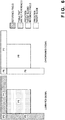
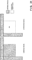
- FIG. 21 shows reference pixels that are necessary for performing luminance/chrominance prediction based on the aforementioned linear prediction according to the conventional example.
- a chrominance signal requires intra-predicted reference pixels P5 that are adjacently to the left of a prediction target block P0, intra-predicted reference pixels P6 that are adjacently to the left of and above the prediction target block P0, and intra-predicted reference pixels P7 that are adjacently above the prediction target block P0.
- a luminance signal requires a reference block P1 that corresponds to the prediction target block and that is used in luminance/chrominance prediction for the luminance signal, intra-predicted reference pixels P2 that are adjacently to the left of the reference block P1, intra-predicted reference pixels P3 that are adjacently to the left of and above the reference block P1, and intra-predicted reference pixels P4 that are adjacently above the reference block P1.
- the reference block P1 of the luminance signal is necessary for predicting the prediction target block P0 of the chrominance signal.
- prediction of a chrominance block m requires local decoding (reconstruction) of a luminance block m to be completed; this gives rise to the problem that the degree of freedom in hardware installation is lowered due to the restraints of processing timings.
- the present invention has been made in view of the above problem, and aims to reduce the restraints of processing timings in intra prediction based on linear prediction.
- the foregoing invention can achieve an advantageous effect similar to the aforementioned advantageous effect.
- the present invention can reduce the restrains of processing timings in linear prediction.
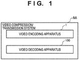
- FIG. 1 is a block diagram of a video compression/transmission system AA according to a first embodiment of the present invention.
- the video compression/transmission system AA includes a video encoding apparatus 1 that generates encoded data (see a bitstream SIG2 in FIGS. 2 and 4 ) by encoding a video, and a video decoding apparatus 100 that decodes the encoded data generated by the video encoding apparatus 1.
- These video encoding apparatus 1 and video decoding apparatus 100 transmit the foregoing encoded data via, for example, a transmission channel.
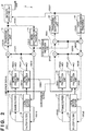
- FIG. 2 is a block diagram of the video encoding apparatus 1.
- the video encoding apparatus 1 includes inter prediction units 11, 21, intra prediction units 12, 22, transform/quantization units 13, 23, inverse quantization/inverse transform units 14, 24, local decode buffers 15, 25, in-loop filters 16, 26, frame buffers 17, 27, an inter-component prediction unit 31, and an entropy encoding unit 32.
- the inter prediction unit 11 receives, as input, a later-described filtered luminance local-decoded image SIG11 fed from the frame buffer 17.
- the inter prediction unit 11 generates luminance inter-predicted pixels SIG13 by performing inter prediction using the filtered luminance local-decoded image SIG11, and outputs the generated pixels.
- the intra prediction unit 12 receives, as input, a later-described unfiltered luminance local-decoded image SIG12 fed from the local decode buffer 15.
- the intra prediction unit 12 generates luminance intra-predicted pixels SIG 14 by performing intra prediction using the unfiltered luminance local-decoded image SIG 12, and outputs the generated pixels.
- the intra prediction unit 12 also generates and outputs luminance intra reference pixels SIG34.
- the intra prediction unit 12 will be described later in detail using FIG. 3 .
- the transform/quantization unit 13 receives a luminance residual signal SIG16 as input.
- the transform/quantization unit 13 generates a luminance quantized coefficient SIG17 by transforming and quantizing the luminance residual signal SIG16, and outputs the generated coefficient.
- the luminance residual signal SIG16 indicates an error (residual) between a luminance signal of an input image SIG 1 and luminance predicted pixels SIG15, and the luminance predicted pixels SIG15 are the luminance inter-predicted pixels SIG13 or the luminance intra-predicted pixels SIG14.
- the inverse quantization/inverse transform unit 14 receives the luminance quantized coefficient SIG17 as input.
- the inverse quantization/inverse transform unit 14 generates an inversely-transformed luminance residual signal SIG18 by inversely quantizing and inversely transforming the luminance quantized coefficient SIG17, and outputs the generated signal.
- the local decode buffer 15 accumulates unfiltered luminance local-decoded images SIG12, and feeds them to the intra prediction unit 12 and the in-loop filter 16 as appropriate.
- an unfiltered luminance local-decoded image SIG12 is a signal obtained by combining luminance predicted pixels SIG15 and an inversely-transformed luminance residual signal SIG18.
- the in-loop filter 16 receives the unfiltered luminance local-decoded image SIG12 as input.
- the in-loop filter 16 generates the filtered luminance local-decoded image SIG11 by applying in-loop filtering, such as deblocking filtering, to the unfiltered luminance local-decoded image SIG12, and outputs the generated image.
- in-loop filtering such as deblocking filtering
- the frame buffer 17 accumulates filtered luminance local-decoded images SIG11, and feeds them to the inter prediction unit 11 as appropriate.
- the inter prediction unit 21 receives, as input, a later-described filtered chrominance local-decoded image SIG21 fed from the frame buffer 27.
- the inter prediction unit 21 generates chrominance inter-predicted pixels SIG23 by performing inter prediction using the filtered chrominance local-decoded image SIG21, and outputs the generated pixels.
- the intra prediction unit 22 receives, as input, a later-described unfiltered chrominance local-decoded image SIG22 fed from the local decode buffer 25, and the aforementioned luminance intra reference pixels SIG34 fed from the intra prediction unit 12.
- the intra prediction unit 22 generates chrominance intra-predicted pixels SIG24 by performing intra prediction using the unfiltered chrominance local-decoded image SIG22 and the luminance intra reference pixels SIG34, and outputs the generated pixels.
- the intra prediction unit 22 will be described later in detail using FIG. 3 .
- the transform/quantization unit 23 receives a chrominance residual signal SIG32 as input.
- the transform/quantization unit 23 generates a chrominance quantized coefficient SIG27 by transforming and quantizing the chrominance residual signal SIG32, and outputs the generated coefficient.
- the chrominance residual signal SIG32 indicates an error (residual) between a chrominance residual signal SIG26 and a later-described chrominance residual correction signal SIG31 fed from the inter-component prediction unit 31.
- the chrominance residual signal SIG26 indicates an error (residual) between a chrominance signal of the input image SIG1 and chrominance predicted pixels SIG25, and the chrominance predicted pixels SIG25 are the chrominance inter-predicted pixels SIG23 or the chrominance intra-predicted pixels SIG24.
- the inverse quantization/inverse transform unit 24 receives the chrominance quantized coefficient SIG27 as input.
- the inverse quantization/inverse transform unit 24 generates an inversely-transformed chrominance residual signal SIG33 by inversely quantizing and inversely transforming the chrominance quantized coefficient SIG27, and outputs the generated signal.
- the local decode buffer 25 accumulates unfiltered chrominance local-decoded images SIG22, and feeds them to the intra prediction unit 22 and the in-loop filter 26 as appropriate.
- an unfiltered chrominance local-decoded image SIG22 is a signal obtained by combining chrominance predicted pixels SIG25 and a chrominance residual signal SIG28
- the chrominance residual signal SIG28 is obtained by combining a chrominance residual correction signal SIG31 and an inversely-transformed chrominance residual signal SIG33.
- the unfiltered chrominance local-decoded image SIG22 can be calculated using the following mathematical expression (5). [Math.
- the in-loop filter 26 receives the unfiltered chrominance local-decoded image SIG22 as input.
- the in-loop filter 26 generates the filtered chrominance local-decoded image SIG21 by applying in-loop filtering, such as deblocking filtering, to the unfiltered chrominance local-decoded image SIG22, and outputs the generated image.
- in-loop filtering such as deblocking filtering
- the frame buffer 27 accumulates filtered chrominance local-decoded images SIG21, and feeds them to the inter prediction unit 21 as appropriate.
- the inter-component prediction unit 31 receives, as input, the inversely-transformed luminance residual signal SIG18 and a prediction coefficient (not shown) that serves as side information.
- the inter-component prediction unit 31 generates the chrominance residual correction signal SIG31 using the following mathematical expression (6), and outputs the generated signal.
- ResScaleVal denotes the prediction coefficient input to the inter-component prediction unit 31.
- the entropy encoding unit 32 receives the luminance quantized coefficient SIG17, the chrominance quantized coefficient SIG27, and non-illustrated side information as input.
- the entropy encoding unit 32 applies entropy encoding to input signals, and outputs the result of entropy encoding as the bitstream SIG2.
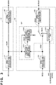
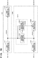
- FIG. 3 is a block diagram of the intra prediction units 12, 22.
- the intra prediction unit 12 includes an intra reference pixel generation unit 121 and an intra-predicted pixel generation unit 122.
- the intra reference pixel generation unit 121 receives, as input, an unfiltered luminance local-decoded image SIG12 of a block i that was decoded before a target block m (note, i ⁇ m).
- the intra reference pixel generation unit 121 first performs reference possibility verification to confirm the local-decoded state of pixels corresponding to reference pixel positions, and when reference is impossible, executes padding processing for generating reference pixels by way of copy from other positions. Then, it applies smoothing processing to the reference pixels using a 3-tap filter, and outputs luminance intra reference pixels SIG34 of the block i.
- the intra-predicted pixel generation unit 122 receives the luminance intra reference pixels SIG34 as input.
- the intra-predicted pixel generation unit 122 generates luminance intra-predicted pixels SIG14 by performing, for example, horizontal, vertical, DC, planar, or directional prediction in accordance with a prediction mode using the luminance intra reference pixels SIG34, and outputs the generated pixels.
- the intra prediction unit 22 includes an inter-channel prediction unit 221, an intra reference pixel generation unit 222, and an intra-predicted pixel generation unit 223.
- the inter-channel prediction unit 221 includes a prediction coefficient deriving unit 2211, an inter-channel reference pixel generation unit 2212, and a determination unit 2213.
- the intra reference pixel generation unit 222 receives, as input, an unfiltered chrominance local-decoded image SIG22 of a block j that was decoded before a target block n (note, j ⁇ n ⁇ m).
- the intra reference pixel generation unit 222 first performs reference possibility verification to confirm the local-decoded state of pixels corresponding to reference pixel positions, and when reference is impossible, executes padding processing for generating reference pixels by way of copy from other positions. Then, it applies smoothing processing to the reference pixels using a 3-tap filter, and outputs chrominance intra reference pixels SIG41 of the block j.
- the intra-predicted pixel generation unit 223 receives chrominance intra reference pixels SIG44 as input.
- the intra-predicted pixel generation unit 223 generates chrominance intra-predicted pixels SIG24 by performing, for example, horizontal, vertical, DC, planar, or directional prediction in accordance with a prediction mode using the chrominance intra reference pixels SIG44, and outputs the generated pixels.
- the chrominance intra reference pixels SIG44 are one of the chrominance intra reference pixels SIG41 and later-described chrominance intra-predicted reference pixels SIG43 fed from the inter-channel reference pixel generation unit 2212.
- the prediction coefficient deriving unit 2211 receives the luminance intra reference pixels SIG34 of the block i and the chrominance intra reference pixels SIG41 of the block j as input.
- the prediction coefficient deriving unit 2211 derives a prediction coefficient SIG42 using the luminance intra reference pixels SIG34 of the block i and the chrominance intra reference pixels SIG41 of the block j in accordance with, for example, a least squares method or a method described in NPL 2, and outputs the derived coefficient.
- the inter-channel reference pixel generation unit 2212 receives the luminance intra reference pixels SIG34 of the block i and the prediction coefficient SIG42 as input.
- the inter-channel reference pixel generation unit 2212 generates the chrominance intra-predicted reference pixels SIG43 using the following mathematical expression (7), and outputs the generated pixels.
- the determination unit 2213 receives the chrominance signal of the input image SIG1 and the chrominance intra-predicted pixels SIG24 as input.
- the determination unit 2213 generates a control signal SIG45 based on the chrominance signal of the input image SIG1 and the chrominance intra-predicted pixels SIG24 so as to select the chrominance intra reference pixels SIG41 or the chrominance intra-predicted reference pixels SIG43 as the chrominance intra reference pixels SIG44 to be fed to the intra-predicted pixel generation unit 223.
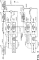
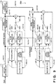
- FIG. 4 is a block diagram of the video decoding apparatus 100.
- the video decoding apparatus 100 includes an entropy decoding unit 101, an inter-component prediction unit 102, inter prediction units 111, 127, intra prediction units 112, 128, inverse quantization/inverse transform units 113, 123, local decode buffers 114, 124, in-loop filters 115, 125, and frame buffers 116, 126.
- the entropy decoding unit 101 receives the bitstream SIG2 as input.
- the entropy decoding unit 101 derives a quantized coefficient level SIG101, as well as relevant information (side information) - e.g., a prediction mode and a motion vector-necessary for reconstructing pixel values, by applying entropy decoding to the bitstream SIG2, and outputs the derived quantized coefficient level and relevant information.
- relevant information e.g., a prediction mode and a motion vector-necessary for reconstructing pixel values
- the inter prediction unit 11 receives, as input, a later-described filtered luminance local-decoded image SIG111 fed from the frame buffer 116.
- the inter prediction unit 111 generates luminance inter-predicted pixels SIG113 by performing inter prediction using the filtered luminance local-decoded image SIG111, and outputs the generated pixels.
- the intra prediction unit 112 receives, as input, a later-described unfiltered luminance local-decoded image SIG112 fed from the local decode buffer 114.
- the intra prediction unit 112 generates luminance intra-predicted pixels SIG114 by performing intra prediction using the unfiltered luminance local-decoded image SIG112, and outputs the generated pixels.
- the intra prediction unit 112 also generates and outputs luminance intra reference pixels SIG104.
- the intra prediction unit 112 will be described later in detail using FIG. 5 .
- the inverse quantization/inverse transform unit 113 receives a luminance signal of the quantized coefficient level SIG101 as input.
- the inverse quantization/inverse transform unit 113 generates an inversely-transformed luminance residual signal SIG115 by inversely quantizing and inversely transforming the luminance signal of the quantized coefficient level SIG101, and outputs the generated signal.
- the local decode buffer 114 accumulates unfiltered luminance local-decoded images SIG112, and feeds them to the intra prediction unit 112 and the in-loop filter 115 as appropriate.
- an unfiltered luminance local-decoded image SIG112 is a signal obtained by combining luminance predicted pixels SIG116 and an inversely-transformed luminance residual signal SIG115, and the luminance predicted pixels SIG116 are the luminance inter-predicted pixels SIG113 or the luminance intra-predicted pixels SIG114.
- the in-loop filter 115 receives the unfiltered luminance local-decoded image SIG112 as input.
- the in-loop filter 115 generates the filtered luminance local-decoded image SIG111 by applying in-loop filtering, such as deblocking filtering, to the unfiltered luminance local-decoded image SIG112, and outputs the generated image.
- in-loop filtering such as deblocking filtering
- the frame buffer 116 accumulates filtered luminance local-decoded images SIG111, and feeds them to the inter prediction unit 111 as appropriate.
- the inter-component prediction unit 102 receives, as input, the inversely-transformed luminance residual signal SIG115 and a prediction coefficient (not shown) that serves as side information.
- the inter-component prediction unit 102 generates a chrominance residual correction signal SIG102 using the following mathematical expression (8), and outputs the generated signal.
- ResScaleVal denotes the prediction coefficient input to the inter-component prediction unit 102.
- the inter prediction unit 127 receives, as input, a later-described filtered chrominance local-decoded image SIG121 fed from the frame buffer 126.
- the inter prediction unit 127 generates chrominance inter-predicted pixels SIG123 by performing inter prediction using the filtered chrominance local-decoded image SIG121, and outputs the generated pixels.
- the intra prediction unit 128 receives, as input, a later-described unfiltered chrominance local-decoded image SIG122 fed from the local decode buffer 124, and the aforementioned luminance intra reference pixels SIG104 fed from the intra prediction unit 112.
- the intra prediction unit 128 generates chrominance intra-predicted pixels SIG124 by performing intra prediction using the unfiltered chrominance local-decoded image SIG122 and the luminance intra reference pixels SIG104, and outputs the generated pixels.
- the intra prediction unit 128 will be described later in detail using FIG. 5 .
- the inverse quantization/inverse transform unit 123 receives a chrominance signal of the quantized coefficient level SIG101 as input.
- the inverse quantization/inverse transform unit 123 generates an inversely-transformed chrominance residual signal SIG125 by inversely quantizing and inversely transforming the chrominance signal of the quantized coefficient level SIG101, and outputs the generated signal.
- the local decode buffer 124 accumulates unfiltered chrominance local-decoded images SIG122, and feeds them to the intra prediction unit 128 and the in-loop filter 125 as appropriate.
- an unfiltered chrominance local-decoded image SIG122 is a signal obtained by combining chrominance predicted pixels SIG126 and a chrominance residual signal SIG103
- the chrominance residual signal SIG103 is obtained by combining an inversely-transformed chrominance residual signal SIG125 and a chrominance residual correction signal SIG102.
- the unfiltered chrominance local-decoded image SIG122 can be calculated using the following mathematical expression (9).
- the chrominance predicted pixels SIG126 are the chrominance inter-predicted pixels SIG123 or the chrominance intra-predicted pixels SIG124.
- the in-loop filter 125 receives the unfiltered chrominance local-decoded image SIG122 as input.
- the in-loop filter 125 generates the filtered chrominance local-decoded image SIG121 by applying in-loop filtering, such as deblocking filtering, to the unfiltered chrominance local-decoded image SIG122, and outputs the generated image.
- in-loop filtering such as deblocking filtering
- the frame buffer 126 accumulates filtered chrominance local-decoded images SIG121, and feeds them to the inter prediction unit 127 as appropriate.
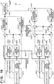
- FIG. 5 is a block diagram of the intra prediction units 112, 128.
- the intra prediction unit 112 includes an intra reference pixel generation unit 1121 and an intra-predicted pixel generation unit 1122.
- the intra reference pixel generation unit 1121 receives, as input, an unfiltered luminance local-decoded image SIG112 of a block i that was decoded before a target block m (note, i ⁇ m).
- the intra reference pixel generation unit 1121 first performs reference possibility verification to confirm the local-decoded state of pixels corresponding to reference pixel positions, and when reference is impossible, executes padding processing for generating reference pixels by way of copy from other positions. Then, it applies smoothing processing to the reference pixels using a 3-tap filter, and outputs luminance intra reference pixels SIG104 of the block i.
- the intra-predicted pixel generation unit 1122 receives the luminance intra reference pixels SIG104 as input.
- the intra-predicted pixel generation unit 1122 generates luminance intra-predicted pixels SIG114 by performing, for example, horizontal, vertical, DC, planar, or directional prediction in accordance with a prediction mode using the luminance intra reference pixels SIG104, and outputs the generated pixels.
- the intra prediction unit 128 includes an inter-channel prediction unit 1281, an intra reference pixel generation unit 1282, and an intra-predicted pixel generation unit 1283.
- the inter-channel prediction unit 1281 includes a prediction coefficient deriving unit 12811, an inter-channel reference pixel generation unit 12812, and a determination unit 12813.
- the intra reference pixel generation unit 1282 receives, as input, an unfiltered chrominance local-decoded image SIG122 of a block j that was decoded before a target block n (note, j ⁇ n ⁇ m).
- the intra reference pixel generation unit 1282 first performs reference possibility verification to confirm the local-decoded state of pixels corresponding to reference pixel positions, and when reference is impossible, executes padding processing for generating reference pixels by way of copy from other positions. Then, it applies smoothing processing to the reference pixels using a 3-tap filter, and outputs chrominance intra reference pixels SIG131 of the block j.
- the intra-predicted pixel generation unit 1283 receives chrominance intra reference pixels SIG134 as input.
- the intra-predicted pixel generation unit 1283 generates chrominance intra-predicted pixels SIG124 by performing, for example, horizontal, vertical, DC, planar, or directional prediction in accordance with a prediction mode using the chrominance intra reference pixels SIG134, and outputs the generated pixels.
- the chrominance intra reference pixels SIG134 are one of the chrominance intra reference pixels SIG131 and later-described chrominance intra-predicted reference pixels SIG133 fed from the inter-channel reference pixel generation unit 12812.
- the prediction coefficient deriving unit 12811 receives the luminance intra reference pixels SIG104 of the block i and the chrominance intra reference pixels SIG131 of the block j as input.
- the prediction coefficient deriving unit 12811 derives a prediction coefficient SIG132 using the luminance intra reference pixels SIG104 of the block i and the chrominance intra reference pixels SIG131 of the block j in accordance with, for example, a least squares method or a method described in NPL 2, and outputs the derived coefficient.
- the inter-channel reference pixel generation unit 12812 receives the luminance intra reference pixels SIG104 of the block i and the prediction coefficient SIG132 as input.
- the inter-channel reference pixel generation unit 12812 generates the chrominance intra-predicted reference pixels SIG133 by performing linear prediction using the following mathematical expression (10), and outputs the generated pixels.
- the determination unit 12813 receives, as input, a non-illustrated signal determined on the encoding side.
- the determination unit 12813 generates a control signal SIG135 based on this signal so as to select the chrominance intra reference pixels SIG131 or the chrominance intra-predicted reference pixels SIG133 as the chrominance intra reference pixels SIG134 to be fed to the intra-predicted pixel generation unit 1283.
- FIG. 6 shows reference pixels that are necessary for performing luminance/chrominance prediction based on linear prediction in the video encoding apparatus 1 and the video decoding apparatus 100.
- the prediction coefficient deriving unit 2211 and the inter-channel reference pixel generation unit 2212 first perform linear prediction of prediction target blocks P5, P6, P7 (the chrominance intra-predicted reference pixels SIG43 of the block i in FIG. 3 ) of the chrominance signal by using intra-predicted reference pixels P2, P3, P4 (the luminance intra reference pixels SIG34 of the block i in FIG. 3 ) of a luminance signal. Then, the intra-predicted pixel generation unit 223 performs intra prediction of the prediction target block P0 (the chrominance intra-predicted pixels SIG24 in FIG. 3 ) of the chrominance signal by using the prediction target blocks P5 to P7 of the chrominance signal as reference pixels.
- the prediction coefficient deriving unit 12811 and the inter-channel reference pixel generation unit 12812 first perform linear prediction of the prediction target blocks P5, P6, P7 (the chrominance intra-predicted reference pixels SIG133 in FIG. 5 ) of the chrominance signal by using the intra-predicted reference pixels P2, P3, P4 (the luminance intra reference pixels SIG104 of the block i in FIG. 5 ) of the luminance signal. Then, the intra-predicted pixel generation unit 1283 performs intra prediction of the prediction target block P0 (the chrominance intra-predicted pixels SIG124 in FIG. 5 ) of the chrominance signal by using the prediction target blocks P5 to P7 of the chrominance signal as reference pixels.
- the video encoding apparatus 1 and the video decoding apparatus 100 do not need a reference block P1 of the luminance signal to predict the prediction target block P0 of the chrominance signal in luminance/chrominance prediction based on linear prediction. For this reason, prediction of the chrominance block m does not require local decoding (reconstruction) of the luminance block m to be completed.
- the foregoing video encoding apparatus 1 can achieve the following advantageous effects.
- the prediction coefficient deriving unit 2211 and the inter-channel reference pixel generation unit 2212 perform linear prediction of the reference pixels P5 to P7 of a chrominance component by using the reference pixels P2 to P4 that are used in intra prediction for a luminance component.
- the intra-predicted pixel generation unit 223 performs intra prediction of the prediction target block P0 of the chrominance component by using the reference pixels P5 to P7 of the chrominance component that have been obtained through linear prediction performed by the prediction coefficient deriving unit 2211 and the inter-channel reference pixel generation unit 2212. Therefore, the reference block P1 of the luminance signal is not necessary in performing intra prediction based on linear prediction with respect to the prediction target block P0 of the chrominance component.
- the intra reference pixel generation unit 121 executes reference possibility verification processing for confirming the local-decoded state of pixels corresponding to reference pixel positions, padding processing for generating reference pixels from positions different from the reference pixel positions when reference has been determined to be impossible in the reference possibility verification processing, and smoothing processing with respect to the reference pixels. Therefore, intra reference pixels can be generated.
- the prediction coefficient deriving unit 2211 derives the prediction coefficient using reference pixels of a prediction target color component and reference pixels of a color component other than the prediction target color component among a plurality of color components. Therefore, the prediction coefficient can be obtained.
- the foregoing video decoding apparatus 100 can achieve the following advantageous effects.
- the prediction coefficient deriving unit 12811 and the inter-channel reference pixel generation unit 12812 perform linear prediction of the reference pixels P5 to P7 of the chrominance component by using the reference pixels P2 to P4 that are used in intra prediction for the luminance component.
- the intra-predicted pixel generation unit 1283 performs intra prediction of the prediction target block P0 of the chrominance component by using the reference pixels P5 to P7 of the chrominance component that have been obtained through linear prediction performed by the prediction coefficient deriving unit 12811 and the inter-channel reference pixel generation unit 12812. Therefore, the reference block P1 of the luminance signal is not necessary in performing intra prediction based on linear prediction with respect to the prediction target block P0 of the chrominance component.
- the intra reference pixel generation unit 1121 executes reference possibility verification processing for confirming the local-decoded state of pixels corresponding to reference pixel positions, padding processing for generating reference pixels from positions different from the reference pixel positions when reference has been determined to be impossible in the reference possibility verification processing, and smoothing processing with respect to the reference pixels. Therefore, intra reference pixels can be generated.
- the prediction coefficient deriving unit 12811 derives the prediction coefficient using reference pixels of a prediction target color component and reference pixels of a color component other than the prediction target color component among a plurality of color components. Therefore, the prediction coefficient can be obtained.
- FIG. 7 is a block diagram of a video encoding apparatus 1A according to a second embodiment of the present invention.
- the video encoding apparatus 1A differs from the video encoding apparatus 1 according to the first embodiment of the present invention shown in FIG. 2 in including an intra prediction unit 22A in place of the intra prediction unit 22. Note that constituents of the video encoding apparatus 1A that are the same as constituents of the video encoding apparatus 1 will be given the same reference signs thereas, and a description thereof will be omitted.
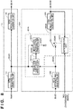
- FIG. 8 is a block diagram of intra prediction units 12, 22A.
- the intra prediction unit 22A includes an inter-channel prediction unit 221A, an intra reference pixel generation unit 222, and an intra-predicted pixel generation unit 223.
- the inter-channel prediction unit 221A includes a prediction coefficient deriving unit 2211A, an inter-channel reference pixel generation unit 2212, and a determination unit 2213.
- the prediction coefficient deriving unit 2211A receives luminance intra reference pixels SIG34 of a block i and chrominance intra reference pixels SIG41 of a block j as input.
- the prediction coefficient deriving unit 2211A selects a prediction coefficient from among a plurality of preset prediction coefficients, and outputs the selected prediction coefficient as a prediction coefficient SIG42.
- the prediction coefficient deriving unit 2211A also transforms indices of the selected prediction coefficient into binary values, and sends a signal indicating the binary values as side information.
- FIG. 9 is a block diagram of a video decoding apparatus 100A according to the second embodiment of the present invention.
- the video decoding apparatus 100A differs from the video decoding apparatus 100 according to the first embodiment of the present invention shown in FIG. 4 in including an intra prediction unit 128A in place of the intra prediction unit 128. Note that constituents of the video decoding apparatus 100A that are the same as constituents of the video decoding apparatus 100 will be given the same reference signs thereas, and a description thereof will be omitted.
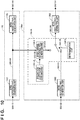
- FIG. 10 is a block diagram of intra prediction units 112, 128A.
- the intra prediction unit 128A includes an inter-channel prediction unit 1281A, an intra reference pixel generation unit 1282, and an intra-predicted pixel generation unit 1283.
- the inter-channel prediction unit 1281A includes a prediction coefficient deriving unit 12811A and an inter-channel reference pixel generation unit 12812.
- the prediction coefficient deriving unit 12811A receives a non-illustrated prediction coefficient signal as input.
- the prediction coefficient deriving unit 12811A selects a prediction coefficient designated by the input prediction coefficient signal from among a plurality of preset prediction coefficients, and outputs the selected prediction coefficient as a prediction coefficient SIG132.
- the foregoing prediction coefficient signal denotes the side information indicated by the signal from the prediction coefficient deriving unit 2211A of the video encoding apparatus 1A.
- the foregoing video encoding apparatus 1A can achieve the following advantageous effect in addition to the aforementioned advantageous effects achieved by the video encoding apparatus 1.
- the prediction coefficient deriving unit 2211A selects a prediction coefficient from among a plurality of preset prediction coefficients. Therefore, the prediction coefficient can be obtained.
- the foregoing video decoding apparatus 100A can achieve the following advantageous effect in addition to the aforementioned advantageous effects achieved by the video decoding apparatus 100.
- the prediction coefficient deriving unit 12811A selects a prediction coefficient corresponding to a signal from the video encoding apparatus 1A from among a plurality of preset prediction coefficients. Therefore, the prediction coefficient can be obtained.
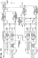
- FIG. 11 is a block diagram of a video encoding apparatus 1B according to a third embodiment of the present invention.
- the video encoding apparatus 1B differs from the video encoding apparatus 1 according to the first embodiment of the present invention shown in FIG. 2 in including an intra prediction unit 22B in place of the intra prediction unit 22. Note that constituents of the video encoding apparatus 1B that are the same as constituents of the video encoding apparatus 1 will be given the same reference signs thereas, and a description thereof will be omitted.
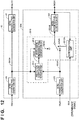
- FIG. 12 is a block diagram of intra prediction units 12, 22B.
- the intra prediction unit 22B includes an inter-channel prediction unit 221B, an intra reference pixel generation unit 222, and an intra-predicted pixel generation unit 223.
- the inter-channel prediction unit 221B includes a prediction coefficient deriving unit 2211, an inter-channel reference pixel generation unit 2212, and a determination unit 2213A.
- the determination unit 2213A receives a chrominance signal of an input image SIG1 and chrominance intra-predicted pixels SIG24 as input.
- the determination unit 2213A generates a control signal SIG45 based on the chrominance signal of the input image SIG1 and the chrominance intra-predicted pixels SIG24 so as to select chrominance intra reference pixels SIG41 or chrominance intra-predicted reference pixels SIG43 as chrominance intra reference pixels SIG44 to be fed to the intra-predicted pixel generation unit 223.
- the determination unit 2213A also determines whether linear prediction is to be performed by a prediction coefficient deriving unit 12811 and an inter-channel reference pixel generation unit 12812 of a video decoding apparatus 100B (see later-described FIG. 14 ) based on the chrominance signal of the input image SIG1 and the chrominance intra-predicted pixels SIG24, and sends a signal indicating the result of determination as one of chrominance intra prediction modes. Accordingly, the number of the chrominance intra prediction mode is added.
- the determination unit 2213A when the determination unit 2213A has determined that linear prediction is to be performed, it makes an arrangement so that a chrominance intra prediction mode is the same as a luminance intra prediction mode.
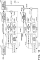
- FIG. 13 is a block diagram of the video decoding apparatus 100B according to the third embodiment of the present invention.
- the video decoding apparatus 100B differs from the video decoding apparatus 100 according to the first embodiment of the present invention shown in FIG. 4 in including an intra prediction unit 128B in place of the intra prediction unit 128. Note that constituents of the video decoding apparatus 100B that are the same as constituents of the video decoding apparatus 100 will be given the same reference signs thereas, and a description thereof will be omitted.
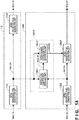
- FIG. 14 is a block diagram of intra prediction units 112, 128B.
- the intra prediction unit 128B includes an inter-channel prediction unit 1281B, an intra reference pixel generation unit 1282, and an intra-predicted pixel generation unit 1283A.
- the inter-channel prediction unit 1281B includes a prediction coefficient deriving unit 12811 and an inter-channel reference pixel generation unit 12812.
- the intra-predicted pixel generation unit 1283A receives chrominance intra reference pixels SIG131, chrominance intra-predicted reference pixels SIG133, and a non-illustrated prediction mode signal as input.
- the intra-predicted pixel generation unit 1283A generates chrominance intra-predicted pixels SIG124 using the chrominance intra-predicted reference pixels SIG133, and outputs the generated pixels.
- the intra-predicted pixel generation unit 1283A when the input prediction mode signal indicates that the chrominance intra reference pixels SIG131 are to be used, the intra-predicted pixel generation unit 1283A generates the chrominance intra-predicted pixels SIG124 using the chrominance intra reference pixels SIG131, and outputs the generated pixels.
- the foregoing input prediction mode signal is the chrominance intra prediction mode indicated by the signal from the determination unit 2213A of the video encoding apparatus 1B.
- the intra-predicted pixel generation unit 1283A makes an arrangement so that a chrominance intra prediction mode is the same as a luminance intra prediction mode.
- the foregoing video encoding apparatus 1B can achieve the following advantageous effect in addition to the aforementioned advantageous effects achieved by the video encoding apparatus 1.
- the determination unit 2213A determines whether linear prediction of a prediction target block is to be performed in the video decoding apparatus 100B, and sends a signal indicating the result of determination as one of chrominance intra prediction modes to the video decoding apparatus 100B.
- the determination unit 2213A has determined that linear prediction of the prediction target block is to be performed in the video decoding apparatus 100B, it makes an arrangement so that a prediction mode for a prediction target color component is the same as a prediction mode for the prediction target color component among a plurality of color components. Therefore, whether linear prediction of the prediction target block is to be performed in the video decoding apparatus 100B can be communicated as one of chrominance intra prediction modes to the video decoding apparatus 100B.
- the foregoing video decoding apparatus 100B can achieve the following advantageous effect in addition to the aforementioned advantageous effects achieved by the video decoding apparatus 100.
- the video decoding apparatus 100B can perform linear prediction in accordance with a signal from the video encoding apparatus 1B.
- FIG. 15 is a block diagram of a video encoding apparatus 1C according to a fourth embodiment of the present invention.
- the video encoding apparatus 1C differs from the video encoding apparatus 1 according to the first embodiment of the present invention shown in FIG. 2 in including an intra prediction unit 22C in place of the intra prediction unit 22. Note that constituents of the video encoding apparatus 1C that are the same as constituents of the video encoding apparatus 1 will be given the same reference signs thereas, and a description thereof will be omitted.
- FIG. 16 is a block diagram of intra prediction units 12, 22C.
- the intra prediction unit 22C includes an inter-channel prediction unit 221C, an intra reference pixel generation unit 222, and an intra-predicted pixel generation unit 223.
- the inter-channel prediction unit 221C includes a prediction coefficient deriving unit 2211, an inter-channel reference pixel generation unit 2212, and a determination unit 2213B.
- the determination unit 2213B receives a chrominance signal of an input image SIG1 and chrominance intra-predicted pixels SIG24 as input.
- the determination unit 2213B generates a control signal SIG45 based on the chrominance signal of the input image SIG1 and the chrominance intra-predicted pixels SIG24 so as to select chrominance intra reference pixels SIG41 or chrominance intra-predicted reference pixels SIG43 as chrominance intra reference pixels SIG44 to be fed to the intra-predicted pixel generation unit 223.
- the determination unit 2213B determines whether linear prediction is to be performed by a prediction coefficient deriving unit 12811 and an inter-channel reference pixel generation unit 12812 of a video decoding apparatus 100C (see later-described FIG. 18 ) based on the chrominance signal of the input image SIG1 and the chrominance intra-predicted pixels SIG24, and sends a signal indicating the result of determination.
- This signaling can be performed using, for example, a flag indicated by a single-digit binary value.
- FIG. 17 is a block diagram of the video decoding apparatus 100C according to the fourth embodiment of the present invention.
- the video decoding apparatus 100C differs from the video decoding apparatus 100 according to the first embodiment of the present invention shown in FIG. 4 in including an intra prediction unit 128C in place of the intra prediction unit 128. Note that constituents of the video decoding apparatus 100C that are the same as constituents of the video decoding apparatus 100 will be given the same reference signs thereas, and a description thereof will be omitted.
- FIG. 18 is a block diagram of intra prediction units 112, 128C.
- the intra prediction unit 128C includes an inter-channel prediction unit 1281B, an intra reference pixel generation unit 1282, and an intra-predicted pixel generation unit 1283B.
- the inter-channel prediction unit 1281B includes a prediction coefficient deriving unit 12811 and an inter-channel reference pixel generation unit 12812.
- the intra-predicted pixel generation unit 1283B receives chrominance intra reference pixels SIG131, chrominance intra-predicted reference pixels SIG133, and a non-illustrated signal as input. When the input signal indicates that the chrominance intra-predicted reference pixels SIG133 are to be used, the intra-predicted pixel generation unit 1283B generates chrominance intra-predicted pixels SIG124 using the chrominance intra-predicted reference pixels SIG133, and outputs the generated pixels.
- the intra-predicted pixel generation unit 1283B when the input signal indicates that the chrominance intra reference pixels SIG131 are to be used, the intra-predicted pixel generation unit 1283B generates the chrominance intra-predicted pixels SIG124 using the chrominance intra reference pixels SIG131, and outputs the generated pixels.
- the foregoing input signal is the signal from the determination unit 2213B of the video encoding apparatus 1C.
- the foregoing video encoding apparatus 1C can achieve the following advantageous effect in addition to the aforementioned advantageous effects achieved by the video encoding apparatus 1.
- the determination unit 2213B determines whether linear prediction of a prediction target block is to be performed in the video decoding apparatus 100C, and sends a signal indicating the result of determination to the video decoding apparatus 100C. Therefore, when the prediction mode for the chrominance component is the same as the prediction mode for the luminance component, whether linear prediction of the prediction target block is to be performed in the video decoding apparatus 100C can be communicated to the video decoding apparatus 100C.
- the foregoing video decoding apparatus 100C can achieve the following advantageous effect in addition to the aforementioned advantageous effects achieved by the video decoding apparatus 100.
- the video decoding apparatus 100C can perform linear prediction in accordance with a signal from the video encoding apparatus 1C.
- FIG. 19 is a block diagram of a video encoding apparatus 1D according to a fifth embodiment of the present invention.
- the video encoding apparatus 1D differs from the video encoding apparatus 1 according to the first embodiment of the present invention shown in FIG. 2 in including an intra prediction unit 22D in place of the intra prediction unit 22. Note that constituents of the video encoding apparatus 1D that are the same as constituents of the video encoding apparatus 1 will be given the same reference signs thereas, and a description thereof will be omitted.
- FIG. 20 is a block diagram of intra prediction units 12, 22D.
- the intra prediction unit 22D includes an inter-channel reference pixel generation unit 2212, an intra reference pixel generation unit 222, an intra-predicted pixel generation unit 223A, a prediction coefficient table 224, an encoding cost deriving unit 225, a residual cost deriving unit 226, and a prediction coefficient determination unit 227.
- the prediction coefficient table 224 receives, as input, a later-described prediction coefficient index SIG51 output from the prediction coefficient determination unit 227.
- the prediction coefficient table 224 stores a plurality of preset prediction coefficients, determines one of the plurality of prediction coefficients that corresponds to the prediction coefficient index SIG51, and outputs the determined prediction coefficient as a prediction coefficient SIG42.
- the encoding cost deriving unit 225 receives the prediction coefficient SIG42 as input.
- the linear prediction for a prediction target block encoding cost deriving unit 225 derives an encoding cost SIG48, which is a product of an approximate encoding amount required in relation to the prediction coefficient SIG42 and a coefficient ⁇ determined by a quantization parameter QP, and outputs the derived encoding cost.
- the residual cost deriving unit 226 receives, as input, a difference signal SIG47 obtained from a chrominance signal of an input image SIG1 and a later-described chrominance predicted signal SIG46 output from the intra-predicted pixel generation unit 223A. For each prediction coefficient available for untransformed and unquantized prediction residual signals for luminance and chrominance with respect to an encoding target block, the residual cost deriving unit 226 derives an SATD, or a sum of absolute values, of Hadamard transform coefficients for the difference signal SIG47 as a residual cost SIG49, and outputs the derived residual cost.
- the prediction coefficient determination unit 227 receives a sum of the encoding cost SIG48 and the residual cost SIG49 as input.
- the prediction coefficient determination unit determines an optimal prediction coefficient, which is a prediction coefficient that yields the smallest sum of the encoding cost SIG48 and the residual cost SIG49 among the plurality of prediction coefficients stored in the prediction coefficient table 224, and outputs the prediction coefficient index SIG51 indicating the determined prediction coefficient.
- the intra-predicted pixel generation unit 223A receives chrominance intra reference pixels SIG44 as input.
- the prediction coefficient determination unit 227 determines the optimal prediction coefficient
- the intra-predicted pixel generation unit 223A generates the chrominance predicted signal SIG46 by performing, for example, horizontal, vertical, DC, planar, or directional prediction in accordance with a prediction mode using the chrominance intra reference pixels SIG44, and outputs the generated signal.
- the intra-predicted pixel generation unit 223A After the prediction coefficient determination unit 227 has determined the optimal prediction coefficient, the intra-predicted pixel generation unit 223A generates chrominance intra-predicted pixels SIG24 by performing, for example, horizontal, vertical, DC, planar, or directional prediction in accordance with a prediction mode using the chrominance intra reference pixels SIG44, and outputs the generated pixels.
- the foregoing video encoding apparatus 1D can achieve the advantageous effects similar to the aforementioned advantageous effects achieved by the video encoding apparatus 1.
- the present invention can be realized by recording processing of the video encoding apparatuses 1, 1A, 1B, 1C, 1D and the video decoding apparatuses 100, 100A, 100B, 100C of the present invention to a computer-readable non-transitory recording medium, and causing the video encoding apparatuses 1, 1A, 1B, 1C, 1D and the video decoding apparatuses 100, 100A, 100B, 100C to read in and execute a program recorded in this recording medium.
- this recording medium examples include: a non-volatile memory, such as an EPROM and a flash memory; a magnetic disk, such as a hard disk; and a CD-ROM.
- the program recorded in this recording medium is read in and executed by processors provided in the video encoding apparatuses 1, 1A, 1B, 1C, 1D and the video decoding apparatuses 100, 100A, 100B, 100C.
- the aforementioned program once stored in storage devices and the like of the video encoding apparatuses 1, 1A, 1B, 1C, 1D and the video decoding apparatuses 100, 100A, 100B, 100C, may be transmitted from these apparatuses to another computer system via a transmission medium or transmission waves of the transmission medium.
- the "transmission medium” for transmitting the program refers to a medium with a function of transmitting information, and examples of such a medium include: a network (communication network), such as the Internet; and a communication line, such as a telephone line.
- the aforementioned program may realize a part of the aforementioned functions.
- the aforementioned program may be a so-called difference file (difference program) that can realize the aforementioned functions in combination with a program that has already been recorded in the video encoding apparatuses 1, 1A, 1B, 1C, 1D and the video decoding apparatuses 100, 100A, 100B, 100C.
- the prediction coefficient deriving unit 2211 may be replaced with the prediction coefficient deriving unit 2211A according to the second embodiment (see FIG. 8 ), and the prediction coefficient deriving unit 12811 (see FIG. 14 ) may be replaced with the prediction coefficient deriving unit 12811A according to the second embodiment (see FIG. 10 ).
- the prediction coefficient deriving unit 2211 may be replaced with the prediction coefficient deriving unit 2211A according to the second embodiment (see FIG. 8 ), and the prediction coefficient deriving unit 12811 (see FIG. 18 ) may be replaced with the prediction coefficient deriving unit 12811A according to the second embodiment (see FIG. 10 ).
Landscapes
- Engineering & Computer Science (AREA)
- Multimedia (AREA)
- Signal Processing (AREA)
- Compression Or Coding Systems Of Tv Signals (AREA)
Applications Claiming Priority (2)
| Application Number | Priority Date | Filing Date | Title |
|---|---|---|---|
| JP2014202509A JP6352141B2 (ja) | 2014-09-30 | 2014-09-30 | 動画像符号化装置、動画像復号装置、動画像圧縮伝送システム、動画像符号化方法、動画像復号方法、およびプログラム |
| PCT/JP2015/069043 WO2016051893A1 (fr) | 2014-09-30 | 2015-07-01 | Dispositif de codage d'image animée, dispositif de décodage d'image animée, système de compression et de transmission d'image animée, procédé de codage d'image animée, procédé de décodage d'image animée, et programme |
Publications (3)
| Publication Number | Publication Date |
|---|---|
| EP3203746A1 true EP3203746A1 (fr) | 2017-08-09 |
| EP3203746A4 EP3203746A4 (fr) | 2017-09-13 |
| EP3203746B1 EP3203746B1 (fr) | 2019-01-09 |
Family
ID=55629946
Family Applications (1)
| Application Number | Title | Priority Date | Filing Date |
|---|---|---|---|
| EP15845627.7A Active EP3203746B1 (fr) | 2014-09-30 | 2015-07-01 | Dispositif de codage de vidéo, dispositif de décodage de vidéo, procédé de codage de vidéo, procédé de décodage de vidéo, et programme |
Country Status (5)
| Country | Link |
|---|---|
| US (1) | US10681366B2 (fr) |
| EP (1) | EP3203746B1 (fr) |
| JP (1) | JP6352141B2 (fr) |
| CN (1) | CN106688237B (fr) |
| WO (1) | WO2016051893A1 (fr) |
Cited By (1)
| Publication number | Priority date | Publication date | Assignee | Title |
|---|---|---|---|---|
| WO2020125794A1 (fr) * | 2018-12-22 | 2020-06-25 | Beijing Bytedance Network Technology Co., Ltd. | Mode de prédiction à composante croisée en deux étapes |
Families Citing this family (13)
| Publication number | Priority date | Publication date | Assignee | Title |
|---|---|---|---|---|
| JP7122838B2 (ja) * | 2017-03-10 | 2022-08-22 | 日本放送協会 | 符号化装置、復号装置及びプログラム |
| GB2571313B (en) * | 2018-02-23 | 2022-09-21 | Canon Kk | New sample sets and new down-sampling schemes for linear component sample prediction |
| WO2019229683A1 (fr) | 2018-05-31 | 2019-12-05 | Beijing Bytedance Network Technology Co., Ltd. | Concept de prédiction entrelacée |
| JP2019213096A (ja) | 2018-06-06 | 2019-12-12 | Kddi株式会社 | 画像復号装置、画像符号化装置、画像処理システム、画像復号方法及びプログラム |
| WO2020002905A1 (fr) * | 2018-06-25 | 2020-01-02 | Immodulon Therapeutics Limited | Thérapie anti-cancéreuse |
| WO2020056767A1 (fr) * | 2018-09-21 | 2020-03-26 | Oppo广东移动通信有限公司 | Procédé et appareil de prédiction de composante d'image vidéo, et support de stockage informatique |
| WO2020140948A1 (fr) | 2019-01-02 | 2020-07-09 | Beijing Bytedance Network Technology Co., Ltd. | Dérivation de vecteur de mouvement entre des motifs de division |
| CN113395520B (zh) * | 2019-01-02 | 2023-05-16 | Oppo广东移动通信有限公司 | 解码预测方法、装置及计算机存储介质 |
| CN119172543A (zh) * | 2019-03-11 | 2024-12-20 | 上海天荷电子信息有限公司 | 多权重可减少分量数的分量间自预测视频解码方法和装置 |
| JP7480170B2 (ja) * | 2019-03-25 | 2024-05-09 | オッポ広東移動通信有限公司 | 画像予測方法、エンコーダー、デコーダー及び記憶媒体 |
| CN119854492A (zh) | 2019-07-12 | 2025-04-18 | Lg 电子株式会社 | 基于变换的图像编译方法及其设备 |
| WO2021054437A1 (fr) * | 2019-09-19 | 2021-03-25 | ソニー株式会社 | Dispositif et procédé de traitement d'image |
| WO2021115235A1 (fr) | 2019-12-08 | 2021-06-17 | Beijing Bytedance Network Technology Co., Ltd. | Prédiction entre composantes au moyen de composantes multiples |
Family Cites Families (8)
| Publication number | Priority date | Publication date | Assignee | Title |
|---|---|---|---|---|
| JP2004007379A (ja) * | 2002-04-10 | 2004-01-08 | Toshiba Corp | 動画像符号化方法及び動画像復号化方法 |
| EP2536151A4 (fr) * | 2010-02-10 | 2014-03-19 | Lg Electronics Inc | Procédé et appareil de traitement de signal vidéo |
| KR101373814B1 (ko) * | 2010-07-31 | 2014-03-18 | 엠앤케이홀딩스 주식회사 | 예측 블록 생성 장치 |
| PH12015501603B1 (en) * | 2010-12-23 | 2023-12-06 | Samsung Electronics Co Ltd | Method and device for encoding intra prediction mode for image prediction unit, and method and device for decoding intra prediction mode for image prediction unit |
| JP2013034163A (ja) * | 2011-06-03 | 2013-02-14 | Sony Corp | 画像処理装置及び画像処理方法 |
| US9693070B2 (en) * | 2011-06-24 | 2017-06-27 | Texas Instruments Incorporated | Luma-based chroma intra-prediction for video coding |
| GB2498982B (en) * | 2012-02-01 | 2014-04-16 | Canon Kk | Method and device for encoding or decoding an image |
| US9736487B2 (en) * | 2013-03-26 | 2017-08-15 | Mediatek Inc. | Method of cross color intra prediction |
-
2014
- 2014-09-30 JP JP2014202509A patent/JP6352141B2/ja active Active
-
2015
- 2015-07-01 CN CN201580041788.3A patent/CN106688237B/zh active Active
- 2015-07-01 EP EP15845627.7A patent/EP3203746B1/fr active Active
- 2015-07-01 WO PCT/JP2015/069043 patent/WO2016051893A1/fr not_active Ceased
-
2017
- 2017-01-11 US US15/403,905 patent/US10681366B2/en active Active
Cited By (6)
| Publication number | Priority date | Publication date | Assignee | Title |
|---|---|---|---|---|
| WO2020125794A1 (fr) * | 2018-12-22 | 2020-06-25 | Beijing Bytedance Network Technology Co., Ltd. | Mode de prédiction à composante croisée en deux étapes |
| CN113273203A (zh) * | 2018-12-22 | 2021-08-17 | 北京字节跳动网络技术有限公司 | 两步交叉分量预测模式 |
| US11570458B2 (en) | 2018-12-22 | 2023-01-31 | Beijing Bytedance Network Technology Co., Ltd. | Indication of two-step cross-component prediction mode |
| US11805268B2 (en) | 2018-12-22 | 2023-10-31 | Beijing Bytedance Network Technology Co., Ltd | Two step cross-component prediction mode |
| CN113273203B (zh) * | 2018-12-22 | 2024-03-12 | 北京字节跳动网络技术有限公司 | 两步交叉分量预测模式 |
| US12368875B2 (en) | 2018-12-22 | 2025-07-22 | Beijing Bytedance Network Technology Co., Ltd. | Two-step cross-component prediction mode |
Also Published As
| Publication number | Publication date |
|---|---|
| JP2016072903A (ja) | 2016-05-09 |
| CN106688237A (zh) | 2017-05-17 |
| EP3203746A4 (fr) | 2017-09-13 |
| EP3203746B1 (fr) | 2019-01-09 |
| CN106688237B (zh) | 2020-02-21 |
| WO2016051893A1 (fr) | 2016-04-07 |
| JP6352141B2 (ja) | 2018-07-04 |
| US10681366B2 (en) | 2020-06-09 |
| US20170127080A1 (en) | 2017-05-04 |
Similar Documents
| Publication | Publication Date | Title |
|---|---|---|
| EP3203746B1 (fr) | Dispositif de codage de vidéo, dispositif de décodage de vidéo, procédé de codage de vidéo, procédé de décodage de vidéo, et programme | |
| US10743033B2 (en) | Method and device for optimizing encoding/decoding of compensation offsets for a set of reconstructed samples of an image | |
| JP7692096B2 (ja) | エンコーダ、デコーダ、及びデブロッキングフィルタの境界強度導出の対応する方法 | |
| AU2015328164B2 (en) | QP derivation and offset for adaptive color transform in video coding | |
| US9544593B2 (en) | Video signal decoding method and device | |
| EP2651127B1 (fr) | Dispositif de traitement d'images et procédé de traitement d'images | |
| US20220191447A1 (en) | Selective use of adaptive in-loop color-space transform and other video coding tools | |
| TWI904047B (zh) | 視訊編碼及解碼之二次轉換 | |
| KR20130034570A (ko) | 제한된 오프셋 보상 및 루프 필터를 이용한 영상 부호화/복호화 방법 및 그 장치 | |
| CN114402609A (zh) | 视频编解码中的色度量化参数 | |
| US11689729B2 (en) | Method and apparatus for video intra prediction involving filtering reference samples based on wide-angle mode | |
| US20220070454A1 (en) | Deblocking filter for video coding | |
| KR20150113523A (ko) | 주관적 품질 향상을 위한 영상 복호화 장치 및 그 방법 | |
| KR20120139608A (ko) | 비디오 인코딩 및 디코딩 방법과 이를 이용한 장치 | |
| WO2026012362A1 (fr) | Réglage de forme de filtre pour filtre à boucle adaptatif dans le codage vidéo | |
| JP6154753B2 (ja) | 動画像復号装置、動画像復号方法、およびプログラム | |
| KR20130070215A (ko) | 적응적 깊이 정보 선택 및 수행에 대한 디블록킹 필터링 방법 및 장치 |
Legal Events
| Date | Code | Title | Description |
|---|---|---|---|
| STAA | Information on the status of an ep patent application or granted ep patent |
Free format text: STATUS: THE INTERNATIONAL PUBLICATION HAS BEEN MADE |
|
| PUAI | Public reference made under article 153(3) epc to a published international application that has entered the european phase |
Free format text: ORIGINAL CODE: 0009012 |
|
| STAA | Information on the status of an ep patent application or granted ep patent |
Free format text: STATUS: REQUEST FOR EXAMINATION WAS MADE |
|
| 17P | Request for examination filed |
Effective date: 20161025 |
|
| AK | Designated contracting states |
Kind code of ref document: A1 Designated state(s): AL AT BE BG CH CY CZ DE DK EE ES FI FR GB GR HR HU IE IS IT LI LT LU LV MC MK MT NL NO PL PT RO RS SE SI SK SM TR |
|
| AX | Request for extension of the european patent |
Extension state: BA ME |
|
| A4 | Supplementary search report drawn up and despatched |
Effective date: 20170810 |
|
| RIC1 | Information provided on ipc code assigned before grant |
Ipc: H04N 19/176 20140101ALI20170804BHEP Ipc: H04N 19/136 20140101ALI20170804BHEP Ipc: H04N 19/186 20140101ALI20170804BHEP Ipc: H04N 19/50 20140101ALI20170804BHEP Ipc: H04N 19/463 20140101ALI20170804BHEP Ipc: H04N 19/159 20140101ALI20170804BHEP Ipc: H04N 19/11 20140101ALI20170804BHEP Ipc: H04N 19/105 20140101ALI20170804BHEP Ipc: H04N 19/593 20140101AFI20170804BHEP |
|
| DAV | Request for validation of the european patent (deleted) | ||
| DAX | Request for extension of the european patent (deleted) | ||
| GRAP | Despatch of communication of intention to grant a patent |
Free format text: ORIGINAL CODE: EPIDOSNIGR1 |
|
| STAA | Information on the status of an ep patent application or granted ep patent |
Free format text: STATUS: GRANT OF PATENT IS INTENDED |
|
| INTG | Intention to grant announced |
Effective date: 20180821 |
|
| GRAS | Grant fee paid |
Free format text: ORIGINAL CODE: EPIDOSNIGR3 |
|
| GRAA | (expected) grant |
Free format text: ORIGINAL CODE: 0009210 |
|
| STAA | Information on the status of an ep patent application or granted ep patent |
Free format text: STATUS: THE PATENT HAS BEEN GRANTED |
|
| AK | Designated contracting states |
Kind code of ref document: B1 Designated state(s): AL AT BE BG CH CY CZ DE DK EE ES FI FR GB GR HR HU IE IS IT LI LT LU LV MC MK MT NL NO PL PT RO RS SE SI SK SM TR |
|
| REG | Reference to a national code |
Ref country code: GB Ref legal event code: FG4D |
|
| REG | Reference to a national code |
Ref country code: CH Ref legal event code: EP Ref country code: AT Ref legal event code: REF Ref document number: 1088789 Country of ref document: AT Kind code of ref document: T Effective date: 20190115 |
|
| REG | Reference to a national code |
Ref country code: IE Ref legal event code: FG4D |
|
| REG | Reference to a national code |
Ref country code: DE Ref legal event code: R096 Ref document number: 602015023411 Country of ref document: DE |
|
| REG | Reference to a national code |
Ref country code: NL Ref legal event code: MP Effective date: 20190109 |
|
| REG | Reference to a national code |
Ref country code: LT Ref legal event code: MG4D |
|
| PG25 | Lapsed in a contracting state [announced via postgrant information from national office to epo] |
Ref country code: NL Free format text: LAPSE BECAUSE OF FAILURE TO SUBMIT A TRANSLATION OF THE DESCRIPTION OR TO PAY THE FEE WITHIN THE PRESCRIBED TIME-LIMIT Effective date: 20190109 |
|
| REG | Reference to a national code |
Ref country code: AT Ref legal event code: MK05 Ref document number: 1088789 Country of ref document: AT Kind code of ref document: T Effective date: 20190109 |
|
| PG25 | Lapsed in a contracting state [announced via postgrant information from national office to epo] |
Ref country code: ES Free format text: LAPSE BECAUSE OF FAILURE TO SUBMIT A TRANSLATION OF THE DESCRIPTION OR TO PAY THE FEE WITHIN THE PRESCRIBED TIME-LIMIT Effective date: 20190109 Ref country code: SE Free format text: LAPSE BECAUSE OF FAILURE TO SUBMIT A TRANSLATION OF THE DESCRIPTION OR TO PAY THE FEE WITHIN THE PRESCRIBED TIME-LIMIT Effective date: 20190109 Ref country code: PT Free format text: LAPSE BECAUSE OF FAILURE TO SUBMIT A TRANSLATION OF THE DESCRIPTION OR TO PAY THE FEE WITHIN THE PRESCRIBED TIME-LIMIT Effective date: 20190509 Ref country code: PL Free format text: LAPSE BECAUSE OF FAILURE TO SUBMIT A TRANSLATION OF THE DESCRIPTION OR TO PAY THE FEE WITHIN THE PRESCRIBED TIME-LIMIT Effective date: 20190109 Ref country code: LT Free format text: LAPSE BECAUSE OF FAILURE TO SUBMIT A TRANSLATION OF THE DESCRIPTION OR TO PAY THE FEE WITHIN THE PRESCRIBED TIME-LIMIT Effective date: 20190109 Ref country code: FI Free format text: LAPSE BECAUSE OF FAILURE TO SUBMIT A TRANSLATION OF THE DESCRIPTION OR TO PAY THE FEE WITHIN THE PRESCRIBED TIME-LIMIT Effective date: 20190109 Ref country code: NO Free format text: LAPSE BECAUSE OF FAILURE TO SUBMIT A TRANSLATION OF THE DESCRIPTION OR TO PAY THE FEE WITHIN THE PRESCRIBED TIME-LIMIT Effective date: 20190409 |
|
| PG25 | Lapsed in a contracting state [announced via postgrant information from national office to epo] |
Ref country code: BG Free format text: LAPSE BECAUSE OF FAILURE TO SUBMIT A TRANSLATION OF THE DESCRIPTION OR TO PAY THE FEE WITHIN THE PRESCRIBED TIME-LIMIT Effective date: 20190409 Ref country code: IS Free format text: LAPSE BECAUSE OF FAILURE TO SUBMIT A TRANSLATION OF THE DESCRIPTION OR TO PAY THE FEE WITHIN THE PRESCRIBED TIME-LIMIT Effective date: 20190509 Ref country code: RS Free format text: LAPSE BECAUSE OF FAILURE TO SUBMIT A TRANSLATION OF THE DESCRIPTION OR TO PAY THE FEE WITHIN THE PRESCRIBED TIME-LIMIT Effective date: 20190109 Ref country code: GR Free format text: LAPSE BECAUSE OF FAILURE TO SUBMIT A TRANSLATION OF THE DESCRIPTION OR TO PAY THE FEE WITHIN THE PRESCRIBED TIME-LIMIT Effective date: 20190410 Ref country code: LV Free format text: LAPSE BECAUSE OF FAILURE TO SUBMIT A TRANSLATION OF THE DESCRIPTION OR TO PAY THE FEE WITHIN THE PRESCRIBED TIME-LIMIT Effective date: 20190109 Ref country code: HR Free format text: LAPSE BECAUSE OF FAILURE TO SUBMIT A TRANSLATION OF THE DESCRIPTION OR TO PAY THE FEE WITHIN THE PRESCRIBED TIME-LIMIT Effective date: 20190109 |
|
| REG | Reference to a national code |
Ref country code: DE Ref legal event code: R097 Ref document number: 602015023411 Country of ref document: DE |
|
| PG25 | Lapsed in a contracting state [announced via postgrant information from national office to epo] |
Ref country code: CZ Free format text: LAPSE BECAUSE OF FAILURE TO SUBMIT A TRANSLATION OF THE DESCRIPTION OR TO PAY THE FEE WITHIN THE PRESCRIBED TIME-LIMIT Effective date: 20190109 Ref country code: IT Free format text: LAPSE BECAUSE OF FAILURE TO SUBMIT A TRANSLATION OF THE DESCRIPTION OR TO PAY THE FEE WITHIN THE PRESCRIBED TIME-LIMIT Effective date: 20190109 Ref country code: SK Free format text: LAPSE BECAUSE OF FAILURE TO SUBMIT A TRANSLATION OF THE DESCRIPTION OR TO PAY THE FEE WITHIN THE PRESCRIBED TIME-LIMIT Effective date: 20190109 Ref country code: AL Free format text: LAPSE BECAUSE OF FAILURE TO SUBMIT A TRANSLATION OF THE DESCRIPTION OR TO PAY THE FEE WITHIN THE PRESCRIBED TIME-LIMIT Effective date: 20190109 Ref country code: DK Free format text: LAPSE BECAUSE OF FAILURE TO SUBMIT A TRANSLATION OF THE DESCRIPTION OR TO PAY THE FEE WITHIN THE PRESCRIBED TIME-LIMIT Effective date: 20190109 Ref country code: AT Free format text: LAPSE BECAUSE OF FAILURE TO SUBMIT A TRANSLATION OF THE DESCRIPTION OR TO PAY THE FEE WITHIN THE PRESCRIBED TIME-LIMIT Effective date: 20190109 Ref country code: EE Free format text: LAPSE BECAUSE OF FAILURE TO SUBMIT A TRANSLATION OF THE DESCRIPTION OR TO PAY THE FEE WITHIN THE PRESCRIBED TIME-LIMIT Effective date: 20190109 Ref country code: RO Free format text: LAPSE BECAUSE OF FAILURE TO SUBMIT A TRANSLATION OF THE DESCRIPTION OR TO PAY THE FEE WITHIN THE PRESCRIBED TIME-LIMIT Effective date: 20190109 |
|
| PLBE | No opposition filed within time limit |
Free format text: ORIGINAL CODE: 0009261 |
|
| STAA | Information on the status of an ep patent application or granted ep patent |
Free format text: STATUS: NO OPPOSITION FILED WITHIN TIME LIMIT |
|
| PG25 | Lapsed in a contracting state [announced via postgrant information from national office to epo] |
Ref country code: SM Free format text: LAPSE BECAUSE OF FAILURE TO SUBMIT A TRANSLATION OF THE DESCRIPTION OR TO PAY THE FEE WITHIN THE PRESCRIBED TIME-LIMIT Effective date: 20190109 |
|
| 26N | No opposition filed |
Effective date: 20191010 |
|
| PG25 | Lapsed in a contracting state [announced via postgrant information from national office to epo] |
Ref country code: SI Free format text: LAPSE BECAUSE OF FAILURE TO SUBMIT A TRANSLATION OF THE DESCRIPTION OR TO PAY THE FEE WITHIN THE PRESCRIBED TIME-LIMIT Effective date: 20190109 Ref country code: MC Free format text: LAPSE BECAUSE OF FAILURE TO SUBMIT A TRANSLATION OF THE DESCRIPTION OR TO PAY THE FEE WITHIN THE PRESCRIBED TIME-LIMIT Effective date: 20190109 |
|
| REG | Reference to a national code |
Ref country code: CH Ref legal event code: PL |
|
| PG25 | Lapsed in a contracting state [announced via postgrant information from national office to epo] |
Ref country code: TR Free format text: LAPSE BECAUSE OF FAILURE TO SUBMIT A TRANSLATION OF THE DESCRIPTION OR TO PAY THE FEE WITHIN THE PRESCRIBED TIME-LIMIT Effective date: 20190109 |
|
| REG | Reference to a national code |
Ref country code: BE Ref legal event code: MM Effective date: 20190731 |
|
| PG25 | Lapsed in a contracting state [announced via postgrant information from national office to epo] |
Ref country code: LI Free format text: LAPSE BECAUSE OF NON-PAYMENT OF DUE FEES Effective date: 20190731 Ref country code: LU Free format text: LAPSE BECAUSE OF NON-PAYMENT OF DUE FEES Effective date: 20190701 Ref country code: CH Free format text: LAPSE BECAUSE OF NON-PAYMENT OF DUE FEES Effective date: 20190731 Ref country code: BE Free format text: LAPSE BECAUSE OF NON-PAYMENT OF DUE FEES Effective date: 20190731 |
|
| PG25 | Lapsed in a contracting state [announced via postgrant information from national office to epo] |
Ref country code: IE Free format text: LAPSE BECAUSE OF NON-PAYMENT OF DUE FEES Effective date: 20190701 |
|
| PG25 | Lapsed in a contracting state [announced via postgrant information from national office to epo] |
Ref country code: CY Free format text: LAPSE BECAUSE OF FAILURE TO SUBMIT A TRANSLATION OF THE DESCRIPTION OR TO PAY THE FEE WITHIN THE PRESCRIBED TIME-LIMIT Effective date: 20190109 |
|
| PG25 | Lapsed in a contracting state [announced via postgrant information from national office to epo] |
Ref country code: MT Free format text: LAPSE BECAUSE OF FAILURE TO SUBMIT A TRANSLATION OF THE DESCRIPTION OR TO PAY THE FEE WITHIN THE PRESCRIBED TIME-LIMIT Effective date: 20190109 Ref country code: HU Free format text: LAPSE BECAUSE OF FAILURE TO SUBMIT A TRANSLATION OF THE DESCRIPTION OR TO PAY THE FEE WITHIN THE PRESCRIBED TIME-LIMIT; INVALID AB INITIO Effective date: 20150701 |
|
| REG | Reference to a national code |
Ref country code: DE Ref legal event code: R082 Ref document number: 602015023411 Country of ref document: DE Representative=s name: ZACCO LEGAL RECHTSANWALTSGESELLSCHAFT MBH, DE |
|
| PG25 | Lapsed in a contracting state [announced via postgrant information from national office to epo] |
Ref country code: MK Free format text: LAPSE BECAUSE OF FAILURE TO SUBMIT A TRANSLATION OF THE DESCRIPTION OR TO PAY THE FEE WITHIN THE PRESCRIBED TIME-LIMIT Effective date: 20190109 |
|
| REG | Reference to a national code |
Ref country code: DE Ref legal event code: R082 Ref document number: 602015023411 Country of ref document: DE |
|
| PGFP | Annual fee paid to national office [announced via postgrant information from national office to epo] |
Ref country code: DE Payment date: 20250722 Year of fee payment: 11 |
|
| PGFP | Annual fee paid to national office [announced via postgrant information from national office to epo] |
Ref country code: GB Payment date: 20250722 Year of fee payment: 11 |
|
| PGFP | Annual fee paid to national office [announced via postgrant information from national office to epo] |
Ref country code: FR Payment date: 20250725 Year of fee payment: 11 |