EP3204066B1 - Nadelschutzanordnung - Google Patents
Nadelschutzanordnung Download PDFInfo
- Publication number
- EP3204066B1 EP3204066B1 EP15770833.0A EP15770833A EP3204066B1 EP 3204066 B1 EP3204066 B1 EP 3204066B1 EP 15770833 A EP15770833 A EP 15770833A EP 3204066 B1 EP3204066 B1 EP 3204066B1
- Authority
- EP
- European Patent Office
- Prior art keywords
- shield
- needle
- hub
- cover assembly
- proximal
- Prior art date
- Legal status (The legal status is an assumption and is not a legal conclusion. Google has not performed a legal analysis and makes no representation as to the accuracy of the status listed.)
- Active
Links
Images


Classifications
-
- A—HUMAN NECESSITIES
- A61—MEDICAL OR VETERINARY SCIENCE; HYGIENE
- A61M—DEVICES FOR INTRODUCING MEDIA INTO, OR ONTO, THE BODY; DEVICES FOR TRANSDUCING BODY MEDIA OR FOR TAKING MEDIA FROM THE BODY; DEVICES FOR PRODUCING OR ENDING SLEEP OR STUPOR
- A61M5/00—Devices for bringing media into the body in a subcutaneous, intra-vascular or intramuscular way; Accessories therefor, e.g. filling or cleaning devices, arm-rests
- A61M5/002—Packages specially adapted therefor, e.g. for syringes or needles, kits for diabetics
-
- A—HUMAN NECESSITIES
- A61—MEDICAL OR VETERINARY SCIENCE; HYGIENE
- A61M—DEVICES FOR INTRODUCING MEDIA INTO, OR ONTO, THE BODY; DEVICES FOR TRANSDUCING BODY MEDIA OR FOR TAKING MEDIA FROM THE BODY; DEVICES FOR PRODUCING OR ENDING SLEEP OR STUPOR
- A61M5/00—Devices for bringing media into the body in a subcutaneous, intra-vascular or intramuscular way; Accessories therefor, e.g. filling or cleaning devices, arm-rests
- A61M5/178—Syringes
- A61M5/31—Details
- A61M5/32—Needles; Details of needles pertaining to their connection with syringe or hub; Accessories for bringing the needle into, or holding the needle on, the body; Devices for protection of needles
- A61M5/3202—Devices for protection of the needle before use, e.g. caps
-
- A—HUMAN NECESSITIES
- A61—MEDICAL OR VETERINARY SCIENCE; HYGIENE
- A61M—DEVICES FOR INTRODUCING MEDIA INTO, OR ONTO, THE BODY; DEVICES FOR TRANSDUCING BODY MEDIA OR FOR TAKING MEDIA FROM THE BODY; DEVICES FOR PRODUCING OR ENDING SLEEP OR STUPOR
- A61M5/00—Devices for bringing media into the body in a subcutaneous, intra-vascular or intramuscular way; Accessories therefor, e.g. filling or cleaning devices, arm-rests
- A61M5/178—Syringes
- A61M5/31—Details
- A61M5/32—Needles; Details of needles pertaining to their connection with syringe or hub; Accessories for bringing the needle into, or holding the needle on, the body; Devices for protection of needles
- A61M5/3205—Apparatus for removing or disposing of used needles or syringes, e.g. containers; Means for protection against accidental injuries from used needles
- A61M5/321—Means for protection against accidental injuries by used needles
- A61M5/3243—Means for protection against accidental injuries by used needles being axially-extensible, e.g. protective sleeves coaxially slidable on the syringe barrel
- A61M5/3245—Constructional features thereof, e.g. to improve manipulation or functioning
-
- A—HUMAN NECESSITIES
- A61—MEDICAL OR VETERINARY SCIENCE; HYGIENE
- A61M—DEVICES FOR INTRODUCING MEDIA INTO, OR ONTO, THE BODY; DEVICES FOR TRANSDUCING BODY MEDIA OR FOR TAKING MEDIA FROM THE BODY; DEVICES FOR PRODUCING OR ENDING SLEEP OR STUPOR
- A61M5/00—Devices for bringing media into the body in a subcutaneous, intra-vascular or intramuscular way; Accessories therefor, e.g. filling or cleaning devices, arm-rests
- A61M5/178—Syringes
- A61M5/31—Details
- A61M5/32—Needles; Details of needles pertaining to their connection with syringe or hub; Accessories for bringing the needle into, or holding the needle on, the body; Devices for protection of needles
- A61M5/3205—Apparatus for removing or disposing of used needles or syringes, e.g. containers; Means for protection against accidental injuries from used needles
- A61M5/321—Means for protection against accidental injuries by used needles
- A61M5/3243—Means for protection against accidental injuries by used needles being axially-extensible, e.g. protective sleeves coaxially slidable on the syringe barrel
- A61M5/326—Fully automatic sleeve extension, i.e. in which triggering of the sleeve does not require a deliberate action by the user
-
- A—HUMAN NECESSITIES
- A61—MEDICAL OR VETERINARY SCIENCE; HYGIENE
- A61M—DEVICES FOR INTRODUCING MEDIA INTO, OR ONTO, THE BODY; DEVICES FOR TRANSDUCING BODY MEDIA OR FOR TAKING MEDIA FROM THE BODY; DEVICES FOR PRODUCING OR ENDING SLEEP OR STUPOR
- A61M5/00—Devices for bringing media into the body in a subcutaneous, intra-vascular or intramuscular way; Accessories therefor, e.g. filling or cleaning devices, arm-rests
- A61M5/178—Syringes
- A61M5/31—Details
- A61M5/32—Needles; Details of needles pertaining to their connection with syringe or hub; Accessories for bringing the needle into, or holding the needle on, the body; Devices for protection of needles
- A61M5/3205—Apparatus for removing or disposing of used needles or syringes, e.g. containers; Means for protection against accidental injuries from used needles
- A61M5/321—Means for protection against accidental injuries by used needles
- A61M5/3243—Means for protection against accidental injuries by used needles being axially-extensible, e.g. protective sleeves coaxially slidable on the syringe barrel
- A61M5/3271—Means for protection against accidental injuries by used needles being axially-extensible, e.g. protective sleeves coaxially slidable on the syringe barrel with guiding tracks for controlled sliding of needle protective sleeve from needle exposing to needle covering position
- A61M5/3272—Means for protection against accidental injuries by used needles being axially-extensible, e.g. protective sleeves coaxially slidable on the syringe barrel with guiding tracks for controlled sliding of needle protective sleeve from needle exposing to needle covering position having projections following labyrinth paths
-
- A—HUMAN NECESSITIES
- A61—MEDICAL OR VETERINARY SCIENCE; HYGIENE
- A61M—DEVICES FOR INTRODUCING MEDIA INTO, OR ONTO, THE BODY; DEVICES FOR TRANSDUCING BODY MEDIA OR FOR TAKING MEDIA FROM THE BODY; DEVICES FOR PRODUCING OR ENDING SLEEP OR STUPOR
- A61M5/00—Devices for bringing media into the body in a subcutaneous, intra-vascular or intramuscular way; Accessories therefor, e.g. filling or cleaning devices, arm-rests
- A61M5/178—Syringes
- A61M5/31—Details
- A61M5/32—Needles; Details of needles pertaining to their connection with syringe or hub; Accessories for bringing the needle into, or holding the needle on, the body; Devices for protection of needles
- A61M5/3286—Needle tip design, e.g. for improved penetration
-
- A—HUMAN NECESSITIES
- A61—MEDICAL OR VETERINARY SCIENCE; HYGIENE
- A61M—DEVICES FOR INTRODUCING MEDIA INTO, OR ONTO, THE BODY; DEVICES FOR TRANSDUCING BODY MEDIA OR FOR TAKING MEDIA FROM THE BODY; DEVICES FOR PRODUCING OR ENDING SLEEP OR STUPOR
- A61M5/00—Devices for bringing media into the body in a subcutaneous, intra-vascular or intramuscular way; Accessories therefor, e.g. filling or cleaning devices, arm-rests
- A61M5/50—Devices for bringing media into the body in a subcutaneous, intra-vascular or intramuscular way; Accessories therefor, e.g. filling or cleaning devices, arm-rests having means for preventing re-use, or for indicating if defective, used, tampered with or unsterile
- A61M5/5086—Devices for bringing media into the body in a subcutaneous, intra-vascular or intramuscular way; Accessories therefor, e.g. filling or cleaning devices, arm-rests having means for preventing re-use, or for indicating if defective, used, tampered with or unsterile for indicating if defective, used, tampered with or unsterile
-
- A—HUMAN NECESSITIES
- A61—MEDICAL OR VETERINARY SCIENCE; HYGIENE
- A61M—DEVICES FOR INTRODUCING MEDIA INTO, OR ONTO, THE BODY; DEVICES FOR TRANSDUCING BODY MEDIA OR FOR TAKING MEDIA FROM THE BODY; DEVICES FOR PRODUCING OR ENDING SLEEP OR STUPOR
- A61M5/00—Devices for bringing media into the body in a subcutaneous, intra-vascular or intramuscular way; Accessories therefor, e.g. filling or cleaning devices, arm-rests
- A61M5/178—Syringes
- A61M5/31—Details
- A61M2005/3103—Leak prevention means for distal end of syringes, i.e. syringe end for mounting a needle
-
- A—HUMAN NECESSITIES
- A61—MEDICAL OR VETERINARY SCIENCE; HYGIENE
- A61M—DEVICES FOR INTRODUCING MEDIA INTO, OR ONTO, THE BODY; DEVICES FOR TRANSDUCING BODY MEDIA OR FOR TAKING MEDIA FROM THE BODY; DEVICES FOR PRODUCING OR ENDING SLEEP OR STUPOR
- A61M5/00—Devices for bringing media into the body in a subcutaneous, intra-vascular or intramuscular way; Accessories therefor, e.g. filling or cleaning devices, arm-rests
- A61M5/178—Syringes
- A61M5/31—Details
- A61M2005/3117—Means preventing contamination of the medicament compartment of a syringe
- A61M2005/3118—Means preventing contamination of the medicament compartment of a syringe via the distal end of a syringe, i.e. syringe end for mounting a needle cannula
-
- A—HUMAN NECESSITIES
- A61—MEDICAL OR VETERINARY SCIENCE; HYGIENE
- A61M—DEVICES FOR INTRODUCING MEDIA INTO, OR ONTO, THE BODY; DEVICES FOR TRANSDUCING BODY MEDIA OR FOR TAKING MEDIA FROM THE BODY; DEVICES FOR PRODUCING OR ENDING SLEEP OR STUPOR
- A61M5/00—Devices for bringing media into the body in a subcutaneous, intra-vascular or intramuscular way; Accessories therefor, e.g. filling or cleaning devices, arm-rests
- A61M5/178—Syringes
- A61M5/31—Details
- A61M2005/3117—Means preventing contamination of the medicament compartment of a syringe
- A61M2005/3121—Means preventing contamination of the medicament compartment of a syringe via the proximal end of a syringe, i.e. syringe end opposite to needle cannula mounting end
-
- A—HUMAN NECESSITIES
- A61—MEDICAL OR VETERINARY SCIENCE; HYGIENE
- A61M—DEVICES FOR INTRODUCING MEDIA INTO, OR ONTO, THE BODY; DEVICES FOR TRANSDUCING BODY MEDIA OR FOR TAKING MEDIA FROM THE BODY; DEVICES FOR PRODUCING OR ENDING SLEEP OR STUPOR
- A61M5/00—Devices for bringing media into the body in a subcutaneous, intra-vascular or intramuscular way; Accessories therefor, e.g. filling or cleaning devices, arm-rests
- A61M5/178—Syringes
- A61M5/31—Details
- A61M5/32—Needles; Details of needles pertaining to their connection with syringe or hub; Accessories for bringing the needle into, or holding the needle on, the body; Devices for protection of needles
- A61M5/3205—Apparatus for removing or disposing of used needles or syringes, e.g. containers; Means for protection against accidental injuries from used needles
- A61M5/321—Means for protection against accidental injuries by used needles
- A61M5/3243—Means for protection against accidental injuries by used needles being axially-extensible, e.g. protective sleeves coaxially slidable on the syringe barrel
- A61M5/3245—Constructional features thereof, e.g. to improve manipulation or functioning
- A61M2005/3247—Means to impede repositioning of protection sleeve from needle covering to needle uncovering position
-
- A—HUMAN NECESSITIES
- A61—MEDICAL OR VETERINARY SCIENCE; HYGIENE
- A61M—DEVICES FOR INTRODUCING MEDIA INTO, OR ONTO, THE BODY; DEVICES FOR TRANSDUCING BODY MEDIA OR FOR TAKING MEDIA FROM THE BODY; DEVICES FOR PRODUCING OR ENDING SLEEP OR STUPOR
- A61M5/00—Devices for bringing media into the body in a subcutaneous, intra-vascular or intramuscular way; Accessories therefor, e.g. filling or cleaning devices, arm-rests
- A61M5/178—Syringes
- A61M5/31—Details
- A61M5/32—Needles; Details of needles pertaining to their connection with syringe or hub; Accessories for bringing the needle into, or holding the needle on, the body; Devices for protection of needles
- A61M5/3205—Apparatus for removing or disposing of used needles or syringes, e.g. containers; Means for protection against accidental injuries from used needles
- A61M5/321—Means for protection against accidental injuries by used needles
- A61M5/3243—Means for protection against accidental injuries by used needles being axially-extensible, e.g. protective sleeves coaxially slidable on the syringe barrel
- A61M5/326—Fully automatic sleeve extension, i.e. in which triggering of the sleeve does not require a deliberate action by the user
- A61M2005/3267—Biased sleeves where the needle is uncovered by insertion of the needle into a patient's body
-
- A—HUMAN NECESSITIES
- A61—MEDICAL OR VETERINARY SCIENCE; HYGIENE
- A61M—DEVICES FOR INTRODUCING MEDIA INTO, OR ONTO, THE BODY; DEVICES FOR TRANSDUCING BODY MEDIA OR FOR TAKING MEDIA FROM THE BODY; DEVICES FOR PRODUCING OR ENDING SLEEP OR STUPOR
- A61M5/00—Devices for bringing media into the body in a subcutaneous, intra-vascular or intramuscular way; Accessories therefor, e.g. filling or cleaning devices, arm-rests
- A61M5/50—Devices for bringing media into the body in a subcutaneous, intra-vascular or intramuscular way; Accessories therefor, e.g. filling or cleaning devices, arm-rests having means for preventing re-use, or for indicating if defective, used, tampered with or unsterile
Definitions
- the present invention is defined in claim 1 and relates to a needle cover assembly to be used with a medicament delivery device, WO 2006/082350 A1 discloses a prior art needle cover assembly.
- a medicament delivery device is loaded with a cartridge containing a liquid drug, after which a disposable needle assembly comprising a double sided injection needle is applied onto the delivery device so that one needle end penetrates the cartridge and contacts its content.
- the medicament can thereafter be delivered by means of injection and the needle assembly is removed and discarded after use.
- Needle assemblies are delivered in a sterile package that may be in the form of an outer cap arranged with a protective film to be removed before use. It is known to provide a further safety protective device covering the injection needle comprising telescopic sleeves which can slide into each other for exposing the needle during injection while covering the needle in neutral state, i.e. when not used for injection procedure. Such safety devices ensure that accidental and possibly dangerous needle sticks are avoided. Examples of safety devices for injection needles are described e.g. in EP0409180 , US10/307054 and US09/870276 .
- a needle cover assembly for a medicament delivery device according to independent claim 1 is provided.
- distal refers to the direction pointing away from the dose delivery site, i.e. a human body.
- distal part/end refers to the part/end of the delivery device, or the parts/ends of the members thereof, which is/are located furthest away from the dose delivery site.
- proximal refers to the direction pointing to the dose delivery site.
- proximal part/end refers to the part/end of the delivery device, or the parts/ends of the members thereof, which is/are located closest to the dose delivery site.
- the needle cover assembly comprises a shield covering a hub holding a double pointed injection needle, said shield and hub each having a generally cylindrical hollow shape and being concentric about a longitudinal axis.
- the shield comprises a detachable element, wherein the shield is attached to the hub when the detachable element is attached to the shield, corresponding to an untampered state, i.e. prior to use, and that the shield is released and is telescopically movable in relation to the hub along the longitudinal axis when said detachable element is detached from the shield corresponding to an activated state, i.e. a state wherein the device is ready for injection procedure.
- the assembly is delivered to a user in the untampered state wherein the shield fully covers the length of the hub and the needle respectively.
- the shield has the function of a protective cap providing a sterile inner environment.
- the detachable element is removed from the shield whereby the shield becomes telescopically movable along the longitudinal axis in relation to the hub which holds the needle.
- Said needle can hereby be exposed by pushing the shield in a distal direction thus collapsing the assembly leading to that the needle is uncovered so that the assembly can be used for injection of medicament.
- the shield will automatically move to a position where the proximal needle end is covered.
- Such an integrated needle shield i.e. a shield that functions as both a protective cap in the untampered state and as a needle safety guard in an active state, provides many advantages. For example it leads to a reduced number of components as no extra external sterile package is required, and thereby also to less waste. Also, the assembly will be easier to produce, requires less material and therefore both manufacturing costs and sales price may be lowered. The user experience will also be improved thanks to that a lesser number of parts must be handled, and further the needle shield is more compact compared to standard variants.
- the detachable element is an integral portion of the shield arranged on the shield with a removable portion provided with at least one tearable or breakable groove enabling peeling off the detachable element from the shield.
- a grippable pull tab may be provided for simplifying peeling manoeuver, wherein said pull tab may be connected to the removable portion.
- the shield has a generally cylindrical hollow shape with one distal open end and an opposite proximal end being partially closed and comprising a central opening.
- the distal open end is sealed e.g. with a film or a label, and the central opening is blocked with a needle seal.
- the shield works as a protective cap which protects the hub and the needle from contamination and provides an inner sterile environment.
- the film When transforming the shield from a protective cap to a needle safety guard, the film may for instance firstly be removed uncovering the distal open end of the shield. This exposes both the distal end of the hub and the distal needle end respectively.
- the distal end of the hub is arranged with a retainer element for attachment of the needle cover assembly to a medicament delivery device holding a cartridge with liquid medicament.
- the retainer element may be any conventional connection including e.g. luer lock, bayonet or threaded connection.
- the needle cover assembly is attached onto the medicament delivery device, which will also lead to that the distal end of the injection needle penetrates a septum of the cartridge and contacts the liquid medicament therein.
- the detachable element of the shield is peeled off and the needle seal removed whereby the shield adapts the function of a needle safety guard. It is understood that the procedure for transforming the shield may be done in another order and that the above procedure is only an example.
- the needle cover assembly comprises a resilient element such as a helical spring located between the hub and the shield, arranged to urge the two components apart, i.e. urging them in opposite directions.
- a resilient element such as a helical spring located between the hub and the shield, arranged to urge the two components apart, i.e. urging them in opposite directions.
- the shield In activated state the shield is urged by the resilient element to automatically adopt a position where it covers the proximal end of the injection needle and prevents unintentional sticks/injuries. Pushing the shield in a distal direction tightens the helical spring and results in collapse of the device whereupon the needle extends through the central opening at the proximal front portion of the shield. This manoeuver permits injection procedure.
- the removable portion of the shield is integral with the needle seal.
- the needle seal is also designed with a pull tab so that peeling is initiated by pulling the pull tab and thereby firstly removing the needle shield to expose the central opening and subsequently in a continuous movement proceed with peeling off the removable portion which is integral with the shield.
- transformation procedure refers to the procedure of removing the removable portion of the shield resulting in that the remaining shield portion becomes movable in relation to the inner hub thus transforming the shield from a protective cap into a needle safety device, also referred to as needle safety guard.
- the removable portion element is separate from the needle seal and the pull tab is situated directly in connection to the detachable element, for instance as a projection of the removable portion on the shield.
- the needle seal is removed in one step and peeling off the removable portion is done in another separate step.
- the shield and the hub are telescopically movable in relation to each other and are engaged with each other by means of a guiding system where the shield is guided along the outside surface of the hub and is movable in a longitudinal direction in relation to said hub.
- a guiding system where the shield is guided along the outside surface of the hub and is movable in a longitudinal direction in relation to said hub.
- the guiding system is arranged with a stopping edge which prevents the shield from sliding out of contact with the hub before injection.
- the guiding system is designed with a safety locking element which provides the function of locking the shield in a position where it fully covers the proximal needle end after injection is completed. The needle cover assembly can thereby be discarded without the risk that the needle is exposed causing injuries to persons handling the waste.
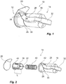
- Figs. 1 and Fig. 2 each show a disposable needle cover assembly 10 according to a first exemplary embodiment having a distal end 12 and a proximal end 14, said assembly being arranged to be used with a medicament delivery device for injection procedures.
- the assembly 10 comprises, among other elements, a substantially cylindrical inner hub 16 covered by a substantially cylindrical outer shield 18 and a protective impermeable seal 20 such as a film, e.g. a protective label, removably attached onto and completely covering the distal open end of the shield 18.
- the hub 16 has a longitudinal axis A (shown in Fig.
- Fig. 3A shows the assembly in an untampered state where the shield 18 encapsulates the proximal needle end 24 as well as the entire hub 16 thereby providing a protective cover, i.e. a protective cap. Together with the film 20 the shield 18 completely covers and protects the hub 16 and injection needle 22 and provides a sterile confinement as well as a container in which the device can be delivered to a consumer. This is also illustrated by the cross section of Fig. 3A .
- the shield 18 further comprises a detachable element 26 which according to the embodiment seen in Fig. 1 comprises a removable portion 28 positioned towards the distal portion 12 of the assembly and arranged to be peelable from the shield 18 by a tearable or breakable, circumferentially extending line or groove 30 pre-arranged on the shield 18 surface as shown e.g. in Fig. 1 and 2 .
- a pull tab 32 may be integrated with the removable portion 28, for instance via a connecting bridge 34 as in Fig. 1 or as a direct prolonged portion of the detachable element 26.
- a further tearable groove 36 is arranged in the vicinity of connecting bridge 34 and is extending somewhat inclined in relation to the longitudinal axis A, as seen in fig. 1 .
- the removable portion 28 is arranged on the shield 18 in such a way that when it is attached the shield 18 is movably attached to the hub 16, corresponding to the untampered state, whereas the shield 18 is telescopically movable in relation to the hub 16 along the longitudinal axis A when said removable portion 28 is detached/removed, corresponding to an activated state.
- the substantially cylindrical shield 18 has a distal open end arranged to be impermeably sealed by said film or label 20, and a partially closed proximal end having a central opening 37, Fig. 3 , with a diameter large enough for the needle to pass through.
- the central opening 37 is plugged by a removable needle seal 38, Fig. 3A .
- the needle seal 38 may be in the form of said pull tab 32 in which case it is connected to the removable portion 26 via the bridge 34, or it may be a separate, independent, plug element.
- a resilient element 40 such as a compression spring is positioned between the hub 16 and the shield 18 and is arranged to urge the hub 16 and the shield 18 apart such that the shield 18 in activated state is urged to automatically move into a position where it covers the proximal end 24 of the injection needle 22.
- This means that the compression spring 40 will safeguard that the proximal needle end 24 will be covered by the shield 18 when the detachable element 26 is removed and the assembly 10 set to activated state leading to that the shield 18 is always urged to move into a proximal needle covering direction.
- Fig. 3A shows a cross section of the assembly 10 in Fig. 1 , wherein the shield 18 comprises said detachable element 26 at the distal portion of the shield and cooperates with said protective film 20 and the needle seal 38 to provide a sterile confinement, housing the hub 16, the injection needle 22 and the compression spring 40.
- the shield 18 is fixed in relation to the hub 16 and a distal flange 42 of the shield 18 is abutting and covering a corresponding distal flange 44 of the hub 16.
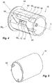
- the shield 18 and the hub 16 are further interconnected via a guiding system 46, Fig. 4 , which prevents the hub 16 and the shield 18 from sliding out of the telescopic engagement seen in Fig. 3A and also prevents uncontrolled rotational movements.
- the protective film 20 provides a certain contribution to stability of the assembly 10 and to that the different components are immobile in relation to each other before use.
- Fig. 3B the needle cover assembly 10 has been prepared for use, i.e. set to activated state wherein it is ready for injection.
- the protective film 20 as well as the needle seal 38 has been removed.
- the detachable element 26 at the distal end 12 of the assembly 10 has been detached e.g. by peeling it off from the shield 18 thus exposing the distal portion of the hub 16 including the distal flange 44.
- a double pointed injection needle 22 is firmly attached to the hub 16 and extends through it along the longitudinal axis A.
- the injection needle 22 has a distal end 48 and a proximal end 24.
- the hub 16 is provided with a retainer element 50 at its distal end portion, Fig.
- the retainer element 50 may be any conventional connection mechanism such as luer lock, bayonet or a threaded connection portion.
- the shield 18 is telescopically movable in relation to the hub 16. This means, pushing the shield 18 in a distal direction B towards the distal flange 44 of the hub results in that the compression spring 40 will be tightened and the proximal needle end 24 will simultaneously extend through the central opening 37 of the shield 18.
- the shield 18 and the hub 16 are engaged with each other via the guiding system 46 by means of which the shield 18 is guided along the outside surface of the hub 16 so that it in an activated state is telescopically movable in relation to said hub.
- the shield 18 is slidably engaged with the hub 16 by means of inwardly directed projections 54 as shown in Fig. 5 , arranged to be guided in guiding slots 56 provided on the hub 16 as shown in Fig. 4 .
- the shield 18 is designed with a number of three projections 54, and the hub 16 consequently has three guiding slots 56 for receiving and guiding the projections 54.
- the number of projections 54 and corresponding guiding slots 56 may vary and is not limited by the example given herein.
- Fig. 4 shows a perspective view of a hub 16 according to one embodiment, comprising an example of a guiding slot 56 positioned substantially longitudinally along the body of the hub 16 allowing for longitudinal telescopic movement of the shield 18.
- the guiding slot 56 comprises a first longitudinally extending portion 56 1 , a second portion 56 2 connected to the first portion 56 1 at an acute angle, and a third longitudinally extending portion 56 3 connected to the second portion 56 2 .
- the first 56 1 and the third portions 56 3 may be arranged to be parallel to each other, i.e. along the longitudinal axis A, however it is also conceivable to arrange the third portion 56 3 as an angled continuation of the second portion 56 2 .
- Each guiding slot 56 commences with an insertion groove 58 arranged at the proximal end of the hub 16.
- the insertion grooves 58 serve the purpose of simplifying connection of the shield 18 and the hub 16 during manufacturing: i.e. the hub 16 is inserted into the shield 18 by firstly sliding the projections 54 into the insertions grooves 58 and further over an inclined surface 60 which ends at a steep stopping edge 62. Upon assembling the assembly 10, the projections 54 of the shield 18 will be moved into the insertions grooves 58, after which they are urged to climb said inclined surface 60 until reaching the top where they snap down at the stopping edges 62. At this point the shield 18 and the hub 16 are irreversibly connected to each other and the projections 54 can no longer slide out of the guiding slot 56.
- Said stopping edge 62 is located at the proximal end of the first portion 56 1 of the guiding slot 56. As previously described, the stopping edge 62 provides a stop for a corresponding projection 54 and prevents the projection 54 once located in the guiding slot 56 from sliding out of it.
- the stopping edge 62 may be in the form of a stopping edge against which edge the projections 54 are resting when the assembly 10 is in neutral state and the compression spring 40 pushes the shield into a needle covering position.
- An elastically deformable safety element 64 is located between the first 56 1 and the second 56 2 portion of the guiding slot 56, and is designed to permit passage of a projection 54 which is guided in the guiding slot 56 in a direction from said first portion 56 1 to said second portion 56 2 , while preventing passage in the opposite direction, i.e. in a direction from said second portion 56 2 to said first portion 56 1 .
- the safety element 64 may be designed as a projecting, elastically deformable tongue designed so that when pressed in a distal direction it will bend to open up a wider passage between the first 56 1 and second 56 2 portion, but flex back so as to close the passage when subjected to pressure in the opposite, proximal direction. In one example this is accomplished by means of said elastically deformable safety element 64 being arranged to project at an angle in relation to the longitudinal axis A, pointing towards said first portion 56 1 .
- the third portion 56 3 of the guiding slot 56 is arranged with a locking element 66 providing the function of engaging a projection 54 and irreversibly locking it in relation to the hub 16.
- a locking element 66 providing the function of engaging a projection 54 and irreversibly locking it in relation to the hub 16.
- the locking element 66 comprises a tongue 68 directed in the proximal direction and flexible in the generally radial direction, wherein the free end of the tongue is arranged with a wedge-shaped elevation 70 ending in a steep edge 72 which, in its turn, faces the proximal direction.
- a projection 54 which is guided towards the locking element 66 will firstly climb the wedge-shaped elevation 70 wherein the tongue 68 is flexing radially inwards and thereafter, upon passing by the steep edge 72, snap into a permanently locked position wherein the tongue 68 flexes back to its original position.
- Figs. 6A and 6B illustrate use of a first embodiment
- Figs. 7A and 7B illustrate use of a second embodiment of a needle cover assembly 10.
- the needle cover assembly 10 is delivered to a user in an untampered state, as seen e.g. in Fig. 1 .
- the shield 18 then acts as a sterile container sealed by said protective film 20.
- the label is removed from the assembly 10 to expose the retainer element 50 of the hub 16 and permitting attaching the assembly 10 onto a medicament delivery device 52 which is loaded with a medicament containing cartridge.
- Such attachment can be accomplished by means of connection via luer lock, bayonet, threads or any other conventional method.
- the distal needle end 48 of the injection needle 22 will pierce the cartridge and contact the liquid medicament inside.
- Figs. 6 - 8 each shows an assembly 10 already attached onto a medicament delivery device 52.
- the shield 18 is thereafter transformed from a protective cap into a functional needle safety guard by pulling off the detachable element 26, which will get the assembly 10 to adopt an activated state in which it is ready for injection.
- the first embodiment (6A-B) has a needle seal 38 outlined as a pull tab integrated with the removable portion 28 of the shield 18 via a connecting bridge 34, see Fig. 1 , whereas in the second embodiment the needle seal 38 is a separate unit, i.e. it is not connected with the removable portion 28.
- a user prepares the assembly for injection by removing the needle seal 38 which plugs the central opening 37 at the distal front of the shield 18.
- the needle seal 38 of the first embodiment is designed as a pull tab 32 which is connected to a removable portion 28 which is integral with the shield 18 and is located towards the distal end 12 of the assembly 10. Pulling the pull tab 32 both leads to removal of the needle seal 38 and to peeling off the removable portion 28 in one continuous movement, see Fig. 6B .
- the assembly 10 is set to an activated state wherein the shield 18 is telescopically movable in relation to the hub 16. In an activated, neutral state the compression spring 40 presses the shield in a proximal direction so that the inner projections 54 rest against the stopping edge 62 of the hub 16, corresponding to a needle covering position.
- a user When preparing the second embodiment, Fig. 7A , for injection a user removes the needle seal 38 in one step and peels off the removable portion 28, in another independent step. As seen in Fig. 7A the needle seal 38 can be twisted off from the shield 18 uncovering the central opening 37, however it is equally conceivable that the needle seal is yet another pull tab or a label or any other suitable sealing element.
- the removable portion 28 of the second embodiment has a pull tab 32 for simplifying gripping.
- Fig. 7B illustrates the step of peeling off the removable portion 28 from an assembly 10 according to a second embodiment. The user grips the pull tab and peels off the spiral wound portion from the shield uncovering the distally located end of the hub 16.
- the needle cover assembly 10 is now ready for injection, as illustrated in Fig. 8 .
- the shield 18 will be guided along the outside surface of the hub 16 by said guiding system 46.
- the function of the guiding system 46 will now be further described, referring mainly to Figs. 9A-C schematically showing the relation between the shield 18 and the hub 16 during an imaginary injection: in reality the assembly 10 is for instance attached to a medicament delivery device 52 whereas in Fig. 9A-C it is shown as an isolated unit.
- the needle cover assembly 10 is seen in an activated state in a start position before injection is initiated.
- the telescopically movable shield 18 is urged by the compression spring 40 to a maximal extended configuration wherein the inwardly directed projections 54 are pressed in a proximal direction onto the stopping edge, at the first portion 56 1 , see Fig. 4 , of the guiding slot 56.
- the shield 18 thus covers the proximal needle end 24 preventing unintentional needle sticks, and the shield is kept in the extended configuration regardless of orientation until injection is commenced.
- Injection may be initiated by pressing the proximal front end of the shield 18 against a delivery site on a patient's body. This will cause the compression spring 40 to compress and the assembly to collapse so that the injection needle 22 extends through the central opening 36 and pierces the skin of the patient. During this movement the shield 18 is guided by the guiding system 46 along the outside surface of the hub 16. The projections 54 slide along the first longitudinally extending portion 56 1 of the guiding slot 56 towards the distal end 12 of the assembly 10 and will pass by said elastically deformable safety element 64 which upon passage of a projection firstly will yield to permit passage and then snap back preventing the projection 54 from returning to the start position.
- the user Upon completion of injection, the user will start removing the assembly 10 from the body. As soon as it is released from outer pressure, the compression spring 40 will expand urging the shield 18 towards a proximal direction for covering the needle 22 as it is retracted from the skin. As the shield 18 moves in said proximal direction, the projections 54 are sliding along the second portion 56 2 having an acute angle, leading to that the shield 18 is slightly rotated in relation to the hub 16. When approaching a maximal extended configuration the projection 54 will be brought into the last, third portion 56 3 of the guiding slot 56 where it engages the locking element 66 and becomes permanently locked in an end position, shown in Fig. 9C .
Landscapes
- Health & Medical Sciences (AREA)
- Engineering & Computer Science (AREA)
- Hematology (AREA)
- Anesthesiology (AREA)
- Biomedical Technology (AREA)
- Heart & Thoracic Surgery (AREA)
- Vascular Medicine (AREA)
- Life Sciences & Earth Sciences (AREA)
- Animal Behavior & Ethology (AREA)
- General Health & Medical Sciences (AREA)
- Public Health (AREA)
- Veterinary Medicine (AREA)
- Environmental & Geological Engineering (AREA)
- Diabetes (AREA)
- Infusion, Injection, And Reservoir Apparatuses (AREA)
Claims (8)
- Nadelschutzanordnung, die mit einer Medikamentenabgabevorrichtung verwendet werden soll, wobei die Nadelschutzanordnung (10) zum einmaligen Gebrauch vorgesehen ist und Folgendes umfasst:- ein Rückhalteelement (50), das mit einem Medikamentenbehälterhalter verbindbar ist,- einen Ansatz (16), der eine Längsachse aufweist und eine doppelspitzige Injektionsnadel (22) mit einem proximalen Nadelende (24) und einem distalen Nadelende (48) umfasst, wobei das proximale Nadelende in einem Abstand von dem Ansatz (16) entlang der Längsachse hervorsteht, und- eine Schutzkappe (18), die mindestens das proximale Nadelende und einen Abschnitt des Ansatzes (16) abdeckt,- wobei die Schutzkappe (18) ein abtrennbares Element (26) umfasst,- wobei die Schutzkappe (18) an dem Ansatz (16) angebracht ist, wenn das abtrennbare Element (26) an der Schutzkappe (18) angebracht ist, was einem unmanipulierten Zustand entspricht, und- wobei die Schutzkappe freigegeben wird und in Bezug auf den Ansatz (16) entlang der Längsachse teleskopisch bewegbar ist, wenn das abtrennbare Element (26) von der Schutzkappe (18) abgenommen wird, was einem aktivierten Zustand entspricht,- wobei die Schutzkappe (18) mit einer proximalen zentralen Öffnung (37) zum Zulassen eines Ausfahrens der Nadel (22) dort hindurch eingerichtet ist,- ein federndes Element (40), das zwischen dem Ansatz (16) und der Schutzkappe (18) positioniert ist, wobei das federnde Element dazu eingerichtet ist, den Ansatz (16) und die Schutzkappe (18) auseinander zu zwängen, so dass die Schutzkappe (18), wenn sie im aktivierten Zustand ist, dazu gezwängt wird, sich automatisch in eine Position zu bewegen, in der sie das proximale Ende der Injektionsnadel (22) abdeckt,- ein Führungssystem (46), wobei die Schutzkappe (18) entlang der Außenfläche des Ansatzes (16) geführt wird und in einer Längsrichtung in Bezug auf den Ansatz (16) teleskopisch bewegbar ist, wobei das Führungssystem (46) mindestens einen, vorzugsweise mindestens zwei nach innen gerichtete Vorsprünge (54), die an der Schutzkappe (18) vorgesehen sind, mindestens einen, vorzugsweise mindestens zwei Führungsschlitze (56) an dem Ansatz (16) umfasst, wobei die Vorsprünge (54) an der Schutzkappe (18) dazu eingerichtet sind, in den Führungsschlitzen (56) an dem Ansatz (16) mithilfe von Gleit- und Arretierelementen (66) zum Ineingriffbringen der Vorsprünge (54) an der Schutzkappe (18) und irreversiblen Arretieren der Schutzkappe (18) in Bezug auf den Ansatz (16) geführt zu werden;
dadurch gekennzeichnet, dass die Schutzkappe (18) mit einer abtrennbaren Nadeldichtung (38) eingerichtet ist, die die zentrale Öffnung (37) in einem unmanipulierten Zustand abdeckt,- eine schützende, abnehmbare, undurchlässige Dichtung (20), die dazu eingerichtet ist, mit der Schutzkappe (18) in einem unmanipulierten Zustand zusammenzuwirken, um ein distales Ende der Nadelschutzanordnung abzudichten, wobei die Dichtung und die Schutzkappe den Ansatz (16) und die Injektionsnadel (22) komplett abdecken und einen sterilen Einschluss für den Ansatz (16) und die Injektionsnadel bereitstellen und einen Behälter bereitstellen. - Nadelschutzanordnung nach Anspruch 1, wobei das abtrennbare Element (26) ein integraler Teil der Schutzkappe (18) ist und einen abtrennbaren Abschnitt (28) und eine Zuglasche (32) zum Zulassen eines Ziehens umfasst, so dass der abtrennbare Abschnitt (28) von der Schutzkappe (18) abgezogen werden kann, wodurch das abtrennbare Element (26) von der Schutzkappe (18) abgetrennt wird.
- Nadelschutzanordnung nach Anspruch 1 oder 2, wobei die Schutzkappe (18) in einem unmanipulierten Zustand dazu eingerichtet ist, die Injektionsnadel (22) und die Länge (L) des Ansatzes (16) vollständig abzudecken.
- Nadelschutzanordnung nach Anspruch 1, wobei jeder der Führungsschlitze (56) mit einem ersten sich längs erstreckenden Abschnitt (561), einem zweiten Abschnitt (562), der mit dem ersten Abschnitt (561) in einem spitzen Winkel verbunden ist, und einem dritten Abschnitt (563), der mit dem zweiten Abschnitt (562) verbunden ist und die Arretierelemente (66) umfasst, eingerichtet ist.
- Nadelschutzanordnung nach Anspruch 1, wobei das Führungssystem (46) weiterhin ein elastisch verformbares Sicherheitselement (64) umfasst, das zwischen dem ersten Abschnitt (561) und dem zweiten Abschnitt (562) eines Führungsschlitzes (56) angeordnet ist, wobei das Sicherheitselement (64) dazu eingerichtet ist, einen Durchtritt eines Vorsprungs (54), der in den Führungsschlitz (56) geführt wird, in einer Richtung von dem ersten Abschnitt (561) zu dem zweiten Abschnitt (562) zuzulassen, und einen Durchtritt eines Vorsprungs (54), der in den Führungsschlitz (56) geführt wird, in einer Richtung von dem zweiten Abschnitt (562) zu dem ersten Abschnitt (561) zu verhindern.
- Nadelschutzanordnung nach Anspruch 1, wobei jedes Arretierelement (66) eine Anschlagkante (62) umfasst, die am proximalen Ende des ersten Abschnitts (561) des Führungsschlitzes (56) angeordnet ist, wobei die Anschlagkante (62) einen Anschlag für den entsprechenden Vorsprung (54) bereitstellt und verhindert, dass der Vorsprung, sobald er in dem Führungsschlitz (56) angeordnet ist, aus dem Schlitz (56) heraus gleitet.
- Nadelschutzanordnung nach Anspruch 1, wobei die Schutzkappe (18) und der Ansatz (16) in einem aktivierten Zustand während des Injektionsvorgangs zwischen mindestens drei unterschiedlichen Stellen verschoben werden können:- Anfangsposition vor der Injektion, in der die Schutzkappe den proximalen Nadelendabschnitt und den proximalen Endabschnitt des Ansatzes vollständig abdeckt,- aktive Position während der Injektion, in der die Schutzkappe in eine distale Richtung bewegt wird, wodurch das federnde Element festgezogen wird und der proximale Nadelendabschnitt zum Eindringen in einen Körper freigelegt wird, und- Endposition, in der die Schutzkappe durch das federnde Element in einen irreversibel arretierten Zustand geschoben wird, wodurch der proximale Nadelendabschnitt vollständig abgedeckt wird.
- Medikamentenabgabevorrichtung, die ein Gehäuse mit einer Längsachse und einen Medikamentenbehälterhalter zum Aufnehmen eines Behälters mit einem Medikament umfasst, wobei die Medikamentenabgabevorrichtung weiterhin eine Nadelschutzanordnung (10) nach einem der vorhergehenden Ansprüche umfasst.
Applications Claiming Priority (2)
| Application Number | Priority Date | Filing Date | Title |
|---|---|---|---|
| SE1451198 | 2014-10-08 | ||
| PCT/EP2015/071052 WO2016055241A1 (en) | 2014-10-08 | 2015-09-15 | Needle cover assembly |
Publications (2)
| Publication Number | Publication Date |
|---|---|
| EP3204066A1 EP3204066A1 (de) | 2017-08-16 |
| EP3204066B1 true EP3204066B1 (de) | 2019-05-01 |
Family
ID=54199184
Family Applications (1)
| Application Number | Title | Priority Date | Filing Date |
|---|---|---|---|
| EP15770833.0A Active EP3204066B1 (de) | 2014-10-08 | 2015-09-15 | Nadelschutzanordnung |
Country Status (4)
| Country | Link |
|---|---|
| US (1) | US10751479B2 (de) |
| EP (1) | EP3204066B1 (de) |
| TW (1) | TWI576131B (de) |
| WO (1) | WO2016055241A1 (de) |
Cited By (1)
| Publication number | Priority date | Publication date | Assignee | Title |
|---|---|---|---|---|
| WO2026050392A1 (en) * | 2024-08-29 | 2026-03-05 | Genzyme Corporation | Medicament delivery device |
Families Citing this family (9)
| Publication number | Priority date | Publication date | Assignee | Title |
|---|---|---|---|---|
| GB2529390A (en) * | 2014-08-12 | 2016-02-24 | Owen Mumford Ltd | Needle assembly |
| WO2017189163A1 (en) * | 2016-04-28 | 2017-11-02 | Becton, Dickinson And Company | Pen needle magazine |
| CN107050573A (zh) * | 2017-05-03 | 2017-08-18 | 贝普医疗科技有限公司 | 一种医用注射器 |
| CA3104425A1 (en) | 2018-06-22 | 2019-12-26 | Becton, Dickinson And Company | Pen needle |
| US11219720B2 (en) * | 2018-10-08 | 2022-01-11 | Dali Medical Devices Ltd. | Safety needle with needle hub, and methods of use thereof |
| MX2023004818A (es) * | 2020-10-27 | 2023-05-10 | Becton Dickinson Co | Sistema de administracion de farmacos, y aparato de barrera y pesta?a de tiro para el mismo. |
| US20250032730A1 (en) * | 2021-12-07 | 2025-01-30 | Shl Medical Ag | A subassembly of a medicament delivery device |
| EP4475917A1 (de) | 2022-02-09 | 2024-12-18 | SHL Medical AG | Röhrenförmige nadelabdeckung einer stiftnadelanordnung |
| EP4716567A1 (de) * | 2023-05-23 | 2026-04-01 | Novo Nordisk A/S | Nadelschutzeinheit mit betätigbarem freigabemerkmal |
Family Cites Families (11)
| Publication number | Priority date | Publication date | Assignee | Title |
|---|---|---|---|---|
| US4664259A (en) * | 1985-05-13 | 1987-05-12 | Robert Landis | Needle container and method for preventing accidental contact with a needle |
| US4693708A (en) * | 1986-10-16 | 1987-09-15 | Wanderer Alan A | Combination needle shield/needle guard device for a hypodermic syringe with a permanently attached needle |
| ES2015427A6 (es) | 1989-07-21 | 1990-08-16 | Sempere Escudero Philippe | Dispositivo protector de alta seguridad para agujas de inyecciones. |
| ATE420687T1 (de) | 2001-11-30 | 2009-01-15 | Novo Nordisk As | Nadelsicherheitsvorrichtung |
| DK1558311T3 (da) * | 2003-02-11 | 2007-04-10 | Salvus Technology Ltd | En sikkerhedsspröjte |
| AU2005326534A1 (en) * | 2005-02-03 | 2006-08-10 | Douglas Arthur Emmott | A safety needle |
| WO2008067467A2 (en) * | 2006-11-29 | 2008-06-05 | West Pharmaceutical Services, Inc. | Syringe cartridge system |
| WO2008118170A1 (en) * | 2007-03-26 | 2008-10-02 | Visual Connections, Inc. | Automatic needle guard for medication pen |
| WO2010126432A1 (en) * | 2009-04-27 | 2010-11-04 | Shl Group Ab | Safety pen needle device |
| US8491535B2 (en) * | 2011-04-28 | 2013-07-23 | Becton, Dickinson And Company | Safety pen needle assembly |
| US8702653B2 (en) * | 2012-02-23 | 2014-04-22 | Unitract Syringe Pty Ltd | Retractable needle safety syringes |
-
2015
- 2015-09-15 US US15/517,870 patent/US10751479B2/en active Active
- 2015-09-15 WO PCT/EP2015/071052 patent/WO2016055241A1/en not_active Ceased
- 2015-09-15 EP EP15770833.0A patent/EP3204066B1/de active Active
- 2015-09-23 TW TW104131480A patent/TWI576131B/zh not_active IP Right Cessation
Non-Patent Citations (1)
| Title |
|---|
| None * |
Cited By (1)
| Publication number | Priority date | Publication date | Assignee | Title |
|---|---|---|---|---|
| WO2026050392A1 (en) * | 2024-08-29 | 2026-03-05 | Genzyme Corporation | Medicament delivery device |
Also Published As
| Publication number | Publication date |
|---|---|
| US10751479B2 (en) | 2020-08-25 |
| TW201625325A (zh) | 2016-07-16 |
| US20170304556A1 (en) | 2017-10-26 |
| EP3204066A1 (de) | 2017-08-16 |
| TWI576131B (zh) | 2017-04-01 |
| WO2016055241A1 (en) | 2016-04-14 |
Similar Documents
| Publication | Publication Date | Title |
|---|---|---|
| EP3204066B1 (de) | Nadelschutzanordnung | |
| US8313470B2 (en) | Autoinjector | |
| CN105592876B (zh) | 安全针设备 | |
| EP2853277B1 (de) | Vorgefüllte Sicherheitsstiftnadel | |
| CN102869399B (zh) | 药物输送装置 | |
| US5181524A (en) | Needle guard for blood collection | |
| EP2588165B1 (de) | Sicherheitsvorrichtung für eine vorgefüllte spritze, injektionsvorrichtung und injektionskit | |
| JP6621974B2 (ja) | 安全装置を備えた注入セット | |
| KR20140027466A (ko) | 주입 장치 | |
| JP2007513731A (ja) | プレフィルド注射器用の安全シールドシステム | |
| US20100036325A1 (en) | Medical Needle Safety Device | |
| CN212439618U (zh) | 笔式针组件 | |
| CN116710162A (zh) | 具有枢转针防护装置的低死腔注射器 | |
| CN115227914A (zh) | 安全组件 | |
| US20250090760A1 (en) | End of dose indicators | |
| WO2024043891A1 (en) | Safety needle and method for using the same |
Legal Events
| Date | Code | Title | Description |
|---|---|---|---|
| STAA | Information on the status of an ep patent application or granted ep patent |
Free format text: STATUS: THE INTERNATIONAL PUBLICATION HAS BEEN MADE |
|
| PUAI | Public reference made under article 153(3) epc to a published international application that has entered the european phase |
Free format text: ORIGINAL CODE: 0009012 |
|
| STAA | Information on the status of an ep patent application or granted ep patent |
Free format text: STATUS: REQUEST FOR EXAMINATION WAS MADE |
|
| 17P | Request for examination filed |
Effective date: 20170209 |
|
| AK | Designated contracting states |
Kind code of ref document: A1 Designated state(s): AL AT BE BG CH CY CZ DE DK EE ES FI FR GB GR HR HU IE IS IT LI LT LU LV MC MK MT NL NO PL PT RO RS SE SI SK SM TR |
|
| AX | Request for extension of the european patent |
Extension state: BA ME |
|
| DAV | Request for validation of the european patent (deleted) | ||
| DAX | Request for extension of the european patent (deleted) | ||
| STAA | Information on the status of an ep patent application or granted ep patent |
Free format text: STATUS: EXAMINATION IS IN PROGRESS |
|
| 17Q | First examination report despatched |
Effective date: 20180409 |
|
| RAP1 | Party data changed (applicant data changed or rights of an application transferred) |
Owner name: SHL MEDICAL AG |
|
| GRAP | Despatch of communication of intention to grant a patent |
Free format text: ORIGINAL CODE: EPIDOSNIGR1 |
|
| STAA | Information on the status of an ep patent application or granted ep patent |
Free format text: STATUS: GRANT OF PATENT IS INTENDED |
|
| INTG | Intention to grant announced |
Effective date: 20181210 |
|
| GRAS | Grant fee paid |
Free format text: ORIGINAL CODE: EPIDOSNIGR3 |
|
| GRAA | (expected) grant |
Free format text: ORIGINAL CODE: 0009210 |
|
| STAA | Information on the status of an ep patent application or granted ep patent |
Free format text: STATUS: THE PATENT HAS BEEN GRANTED |
|
| AK | Designated contracting states |
Kind code of ref document: B1 Designated state(s): AL AT BE BG CH CY CZ DE DK EE ES FI FR GB GR HR HU IE IS IT LI LT LU LV MC MK MT NL NO PL PT RO RS SE SI SK SM TR |
|
| REG | Reference to a national code |
Ref country code: GB Ref legal event code: FG4D |
|
| REG | Reference to a national code |
Ref country code: CH Ref legal event code: EP Ref country code: AT Ref legal event code: REF Ref document number: 1126078 Country of ref document: AT Kind code of ref document: T Effective date: 20190515 |
|
| REG | Reference to a national code |
Ref country code: DE Ref legal event code: R096 Ref document number: 602015029384 Country of ref document: DE |
|
| REG | Reference to a national code |
Ref country code: IE Ref legal event code: FG4D |
|
| REG | Reference to a national code |
Ref country code: NL Ref legal event code: MP Effective date: 20190501 |
|
| REG | Reference to a national code |
Ref country code: LT Ref legal event code: MG4D |
|
| PG25 | Lapsed in a contracting state [announced via postgrant information from national office to epo] |
Ref country code: NO Free format text: LAPSE BECAUSE OF FAILURE TO SUBMIT A TRANSLATION OF THE DESCRIPTION OR TO PAY THE FEE WITHIN THE PRESCRIBED TIME-LIMIT Effective date: 20190801 Ref country code: PT Free format text: LAPSE BECAUSE OF FAILURE TO SUBMIT A TRANSLATION OF THE DESCRIPTION OR TO PAY THE FEE WITHIN THE PRESCRIBED TIME-LIMIT Effective date: 20190901 Ref country code: FI Free format text: LAPSE BECAUSE OF FAILURE TO SUBMIT A TRANSLATION OF THE DESCRIPTION OR TO PAY THE FEE WITHIN THE PRESCRIBED TIME-LIMIT Effective date: 20190501 Ref country code: AL Free format text: LAPSE BECAUSE OF FAILURE TO SUBMIT A TRANSLATION OF THE DESCRIPTION OR TO PAY THE FEE WITHIN THE PRESCRIBED TIME-LIMIT Effective date: 20190501 Ref country code: SE Free format text: LAPSE BECAUSE OF FAILURE TO SUBMIT A TRANSLATION OF THE DESCRIPTION OR TO PAY THE FEE WITHIN THE PRESCRIBED TIME-LIMIT Effective date: 20190501 Ref country code: HR Free format text: LAPSE BECAUSE OF FAILURE TO SUBMIT A TRANSLATION OF THE DESCRIPTION OR TO PAY THE FEE WITHIN THE PRESCRIBED TIME-LIMIT Effective date: 20190501 Ref country code: LT Free format text: LAPSE BECAUSE OF FAILURE TO SUBMIT A TRANSLATION OF THE DESCRIPTION OR TO PAY THE FEE WITHIN THE PRESCRIBED TIME-LIMIT Effective date: 20190501 Ref country code: ES Free format text: LAPSE BECAUSE OF FAILURE TO SUBMIT A TRANSLATION OF THE DESCRIPTION OR TO PAY THE FEE WITHIN THE PRESCRIBED TIME-LIMIT Effective date: 20190501 Ref country code: NL Free format text: LAPSE BECAUSE OF FAILURE TO SUBMIT A TRANSLATION OF THE DESCRIPTION OR TO PAY THE FEE WITHIN THE PRESCRIBED TIME-LIMIT Effective date: 20190501 |
|
| PG25 | Lapsed in a contracting state [announced via postgrant information from national office to epo] |
Ref country code: LV Free format text: LAPSE BECAUSE OF FAILURE TO SUBMIT A TRANSLATION OF THE DESCRIPTION OR TO PAY THE FEE WITHIN THE PRESCRIBED TIME-LIMIT Effective date: 20190501 Ref country code: RS Free format text: LAPSE BECAUSE OF FAILURE TO SUBMIT A TRANSLATION OF THE DESCRIPTION OR TO PAY THE FEE WITHIN THE PRESCRIBED TIME-LIMIT Effective date: 20190501 Ref country code: BG Free format text: LAPSE BECAUSE OF FAILURE TO SUBMIT A TRANSLATION OF THE DESCRIPTION OR TO PAY THE FEE WITHIN THE PRESCRIBED TIME-LIMIT Effective date: 20190801 Ref country code: GR Free format text: LAPSE BECAUSE OF FAILURE TO SUBMIT A TRANSLATION OF THE DESCRIPTION OR TO PAY THE FEE WITHIN THE PRESCRIBED TIME-LIMIT Effective date: 20190802 |
|
| REG | Reference to a national code |
Ref country code: AT Ref legal event code: MK05 Ref document number: 1126078 Country of ref document: AT Kind code of ref document: T Effective date: 20190501 |
|
| PG25 | Lapsed in a contracting state [announced via postgrant information from national office to epo] |
Ref country code: IS Free format text: LAPSE BECAUSE OF FAILURE TO SUBMIT A TRANSLATION OF THE DESCRIPTION OR TO PAY THE FEE WITHIN THE PRESCRIBED TIME-LIMIT Effective date: 20190901 |
|
| PG25 | Lapsed in a contracting state [announced via postgrant information from national office to epo] |
Ref country code: CZ Free format text: LAPSE BECAUSE OF FAILURE TO SUBMIT A TRANSLATION OF THE DESCRIPTION OR TO PAY THE FEE WITHIN THE PRESCRIBED TIME-LIMIT Effective date: 20190501 Ref country code: SK Free format text: LAPSE BECAUSE OF FAILURE TO SUBMIT A TRANSLATION OF THE DESCRIPTION OR TO PAY THE FEE WITHIN THE PRESCRIBED TIME-LIMIT Effective date: 20190501 Ref country code: DK Free format text: LAPSE BECAUSE OF FAILURE TO SUBMIT A TRANSLATION OF THE DESCRIPTION OR TO PAY THE FEE WITHIN THE PRESCRIBED TIME-LIMIT Effective date: 20190501 Ref country code: EE Free format text: LAPSE BECAUSE OF FAILURE TO SUBMIT A TRANSLATION OF THE DESCRIPTION OR TO PAY THE FEE WITHIN THE PRESCRIBED TIME-LIMIT Effective date: 20190501 Ref country code: AT Free format text: LAPSE BECAUSE OF FAILURE TO SUBMIT A TRANSLATION OF THE DESCRIPTION OR TO PAY THE FEE WITHIN THE PRESCRIBED TIME-LIMIT Effective date: 20190501 Ref country code: RO Free format text: LAPSE BECAUSE OF FAILURE TO SUBMIT A TRANSLATION OF THE DESCRIPTION OR TO PAY THE FEE WITHIN THE PRESCRIBED TIME-LIMIT Effective date: 20190501 |
|
| REG | Reference to a national code |
Ref country code: DE Ref legal event code: R097 Ref document number: 602015029384 Country of ref document: DE |
|
| PG25 | Lapsed in a contracting state [announced via postgrant information from national office to epo] |
Ref country code: IT Free format text: LAPSE BECAUSE OF FAILURE TO SUBMIT A TRANSLATION OF THE DESCRIPTION OR TO PAY THE FEE WITHIN THE PRESCRIBED TIME-LIMIT Effective date: 20190501 Ref country code: SM Free format text: LAPSE BECAUSE OF FAILURE TO SUBMIT A TRANSLATION OF THE DESCRIPTION OR TO PAY THE FEE WITHIN THE PRESCRIBED TIME-LIMIT Effective date: 20190501 |
|
| PLBE | No opposition filed within time limit |
Free format text: ORIGINAL CODE: 0009261 |
|
| STAA | Information on the status of an ep patent application or granted ep patent |
Free format text: STATUS: NO OPPOSITION FILED WITHIN TIME LIMIT |
|
| PG25 | Lapsed in a contracting state [announced via postgrant information from national office to epo] |
Ref country code: TR Free format text: LAPSE BECAUSE OF FAILURE TO SUBMIT A TRANSLATION OF THE DESCRIPTION OR TO PAY THE FEE WITHIN THE PRESCRIBED TIME-LIMIT Effective date: 20190501 |
|
| 26N | No opposition filed |
Effective date: 20200204 |
|
| PG25 | Lapsed in a contracting state [announced via postgrant information from national office to epo] |
Ref country code: PL Free format text: LAPSE BECAUSE OF FAILURE TO SUBMIT A TRANSLATION OF THE DESCRIPTION OR TO PAY THE FEE WITHIN THE PRESCRIBED TIME-LIMIT Effective date: 20190501 |
|
| PG25 | Lapsed in a contracting state [announced via postgrant information from national office to epo] |
Ref country code: SI Free format text: LAPSE BECAUSE OF FAILURE TO SUBMIT A TRANSLATION OF THE DESCRIPTION OR TO PAY THE FEE WITHIN THE PRESCRIBED TIME-LIMIT Effective date: 20190501 Ref country code: MC Free format text: LAPSE BECAUSE OF FAILURE TO SUBMIT A TRANSLATION OF THE DESCRIPTION OR TO PAY THE FEE WITHIN THE PRESCRIBED TIME-LIMIT Effective date: 20190501 |
|
| PG25 | Lapsed in a contracting state [announced via postgrant information from national office to epo] |
Ref country code: LU Free format text: LAPSE BECAUSE OF NON-PAYMENT OF DUE FEES Effective date: 20190915 Ref country code: IE Free format text: LAPSE BECAUSE OF NON-PAYMENT OF DUE FEES Effective date: 20190915 |
|
| REG | Reference to a national code |
Ref country code: BE Ref legal event code: MM Effective date: 20190930 |
|
| PG25 | Lapsed in a contracting state [announced via postgrant information from national office to epo] |
Ref country code: BE Free format text: LAPSE BECAUSE OF NON-PAYMENT OF DUE FEES Effective date: 20190930 |
|
| PG25 | Lapsed in a contracting state [announced via postgrant information from national office to epo] |
Ref country code: CY Free format text: LAPSE BECAUSE OF FAILURE TO SUBMIT A TRANSLATION OF THE DESCRIPTION OR TO PAY THE FEE WITHIN THE PRESCRIBED TIME-LIMIT Effective date: 20190501 |
|
| PG25 | Lapsed in a contracting state [announced via postgrant information from national office to epo] |
Ref country code: MT Free format text: LAPSE BECAUSE OF FAILURE TO SUBMIT A TRANSLATION OF THE DESCRIPTION OR TO PAY THE FEE WITHIN THE PRESCRIBED TIME-LIMIT Effective date: 20190501 Ref country code: HU Free format text: LAPSE BECAUSE OF FAILURE TO SUBMIT A TRANSLATION OF THE DESCRIPTION OR TO PAY THE FEE WITHIN THE PRESCRIBED TIME-LIMIT; INVALID AB INITIO Effective date: 20150915 |
|
| PG25 | Lapsed in a contracting state [announced via postgrant information from national office to epo] |
Ref country code: MK Free format text: LAPSE BECAUSE OF FAILURE TO SUBMIT A TRANSLATION OF THE DESCRIPTION OR TO PAY THE FEE WITHIN THE PRESCRIBED TIME-LIMIT Effective date: 20190501 |
|
| P01 | Opt-out of the competence of the unified patent court (upc) registered |
Effective date: 20230425 |
|
| PGFP | Annual fee paid to national office [announced via postgrant information from national office to epo] |
Ref country code: GB Payment date: 20240801 Year of fee payment: 10 |
|
| PGFP | Annual fee paid to national office [announced via postgrant information from national office to epo] |
Ref country code: FR Payment date: 20240821 Year of fee payment: 10 |
|
| PGFP | Annual fee paid to national office [announced via postgrant information from national office to epo] |
Ref country code: CH Payment date: 20241001 Year of fee payment: 10 |
|
| PGFP | Annual fee paid to national office [announced via postgrant information from national office to epo] |
Ref country code: DE Payment date: 20250926 Year of fee payment: 11 |