EP3204271B1 - Hydraulisches sicherheitssystem, bremsanlage und betriebsverfahren - Google Patents
Hydraulisches sicherheitssystem, bremsanlage und betriebsverfahren Download PDFInfo
- Publication number
- EP3204271B1 EP3204271B1 EP15771610.1A EP15771610A EP3204271B1 EP 3204271 B1 EP3204271 B1 EP 3204271B1 EP 15771610 A EP15771610 A EP 15771610A EP 3204271 B1 EP3204271 B1 EP 3204271B1
- Authority
- EP
- European Patent Office
- Prior art keywords
- brake
- pressure
- subchamber
- hydraulic
- piston
- Prior art date
- Legal status (The legal status is an assumption and is not a legal conclusion. Google has not performed a legal analysis and makes no representation as to the accuracy of the status listed.)
- Not-in-force
Links
- 238000011017 operating method Methods 0.000 title 1
- 230000000903 blocking effect Effects 0.000 claims description 9
- 239000012530 fluid Substances 0.000 claims description 9
- 238000000034 method Methods 0.000 claims description 7
- 238000007789 sealing Methods 0.000 claims description 6
- 210000003205 muscle Anatomy 0.000 description 3
- 230000001419 dependent effect Effects 0.000 description 1
- 238000001514 detection method Methods 0.000 description 1
- 238000002955 isolation Methods 0.000 description 1
- 230000007257 malfunction Effects 0.000 description 1
- 230000003387 muscular Effects 0.000 description 1
- 230000035484 reaction time Effects 0.000 description 1
Images

Classifications
-
- B—PERFORMING OPERATIONS; TRANSPORTING
- B60—VEHICLES IN GENERAL
- B60T—VEHICLE BRAKE CONTROL SYSTEMS OR PARTS THEREOF; BRAKE CONTROL SYSTEMS OR PARTS THEREOF, IN GENERAL; ARRANGEMENT OF BRAKING ELEMENTS ON VEHICLES IN GENERAL; PORTABLE DEVICES FOR PREVENTING UNWANTED MOVEMENT OF VEHICLES; VEHICLE MODIFICATIONS TO FACILITATE COOLING OF BRAKES
- B60T13/00—Transmitting braking action from initiating means to ultimate brake actuator with power assistance or drive; Brake systems incorporating such transmitting means, e.g. air-pressure brake systems
- B60T13/10—Transmitting braking action from initiating means to ultimate brake actuator with power assistance or drive; Brake systems incorporating such transmitting means, e.g. air-pressure brake systems with fluid assistance, drive, or release
- B60T13/12—Transmitting braking action from initiating means to ultimate brake actuator with power assistance or drive; Brake systems incorporating such transmitting means, e.g. air-pressure brake systems with fluid assistance, drive, or release the fluid being liquid
- B60T13/14—Transmitting braking action from initiating means to ultimate brake actuator with power assistance or drive; Brake systems incorporating such transmitting means, e.g. air-pressure brake systems with fluid assistance, drive, or release the fluid being liquid using accumulators or reservoirs fed by pumps
- B60T13/142—Systems with master cylinder
- B60T13/145—Master cylinder integrated or hydraulically coupled with booster
-
- B—PERFORMING OPERATIONS; TRANSPORTING
- B60—VEHICLES IN GENERAL
- B60T—VEHICLE BRAKE CONTROL SYSTEMS OR PARTS THEREOF; BRAKE CONTROL SYSTEMS OR PARTS THEREOF, IN GENERAL; ARRANGEMENT OF BRAKING ELEMENTS ON VEHICLES IN GENERAL; PORTABLE DEVICES FOR PREVENTING UNWANTED MOVEMENT OF VEHICLES; VEHICLE MODIFICATIONS TO FACILITATE COOLING OF BRAKES
- B60T13/00—Transmitting braking action from initiating means to ultimate brake actuator with power assistance or drive; Brake systems incorporating such transmitting means, e.g. air-pressure brake systems
- B60T13/10—Transmitting braking action from initiating means to ultimate brake actuator with power assistance or drive; Brake systems incorporating such transmitting means, e.g. air-pressure brake systems with fluid assistance, drive, or release
- B60T13/66—Electrical control in fluid-pressure brake systems
-
- B—PERFORMING OPERATIONS; TRANSPORTING
- B60—VEHICLES IN GENERAL
- B60T—VEHICLE BRAKE CONTROL SYSTEMS OR PARTS THEREOF; BRAKE CONTROL SYSTEMS OR PARTS THEREOF, IN GENERAL; ARRANGEMENT OF BRAKING ELEMENTS ON VEHICLES IN GENERAL; PORTABLE DEVICES FOR PREVENTING UNWANTED MOVEMENT OF VEHICLES; VEHICLE MODIFICATIONS TO FACILITATE COOLING OF BRAKES
- B60T13/00—Transmitting braking action from initiating means to ultimate brake actuator with power assistance or drive; Brake systems incorporating such transmitting means, e.g. air-pressure brake systems
- B60T13/10—Transmitting braking action from initiating means to ultimate brake actuator with power assistance or drive; Brake systems incorporating such transmitting means, e.g. air-pressure brake systems with fluid assistance, drive, or release
- B60T13/66—Electrical control in fluid-pressure brake systems
- B60T13/68—Electrical control in fluid-pressure brake systems by electrically-controlled valves
-
- B—PERFORMING OPERATIONS; TRANSPORTING
- B60—VEHICLES IN GENERAL
- B60T—VEHICLE BRAKE CONTROL SYSTEMS OR PARTS THEREOF; BRAKE CONTROL SYSTEMS OR PARTS THEREOF, IN GENERAL; ARRANGEMENT OF BRAKING ELEMENTS ON VEHICLES IN GENERAL; PORTABLE DEVICES FOR PREVENTING UNWANTED MOVEMENT OF VEHICLES; VEHICLE MODIFICATIONS TO FACILITATE COOLING OF BRAKES
- B60T13/00—Transmitting braking action from initiating means to ultimate brake actuator with power assistance or drive; Brake systems incorporating such transmitting means, e.g. air-pressure brake systems
- B60T13/10—Transmitting braking action from initiating means to ultimate brake actuator with power assistance or drive; Brake systems incorporating such transmitting means, e.g. air-pressure brake systems with fluid assistance, drive, or release
- B60T13/66—Electrical control in fluid-pressure brake systems
- B60T13/68—Electrical control in fluid-pressure brake systems by electrically-controlled valves
- B60T13/686—Electrical control in fluid-pressure brake systems by electrically-controlled valves in hydraulic systems or parts thereof
-
- B—PERFORMING OPERATIONS; TRANSPORTING
- B60—VEHICLES IN GENERAL
- B60T—VEHICLE BRAKE CONTROL SYSTEMS OR PARTS THEREOF; BRAKE CONTROL SYSTEMS OR PARTS THEREOF, IN GENERAL; ARRANGEMENT OF BRAKING ELEMENTS ON VEHICLES IN GENERAL; PORTABLE DEVICES FOR PREVENTING UNWANTED MOVEMENT OF VEHICLES; VEHICLE MODIFICATIONS TO FACILITATE COOLING OF BRAKES
- B60T13/00—Transmitting braking action from initiating means to ultimate brake actuator with power assistance or drive; Brake systems incorporating such transmitting means, e.g. air-pressure brake systems
- B60T13/74—Transmitting braking action from initiating means to ultimate brake actuator with power assistance or drive; Brake systems incorporating such transmitting means, e.g. air-pressure brake systems with electrical assistance or drive
-
- B—PERFORMING OPERATIONS; TRANSPORTING
- B60—VEHICLES IN GENERAL
- B60T—VEHICLE BRAKE CONTROL SYSTEMS OR PARTS THEREOF; BRAKE CONTROL SYSTEMS OR PARTS THEREOF, IN GENERAL; ARRANGEMENT OF BRAKING ELEMENTS ON VEHICLES IN GENERAL; PORTABLE DEVICES FOR PREVENTING UNWANTED MOVEMENT OF VEHICLES; VEHICLE MODIFICATIONS TO FACILITATE COOLING OF BRAKES
- B60T17/00—Component parts, details, or accessories of power brake systems not covered by groups B60T8/00, B60T13/00 or B60T15/00, or presenting other characteristic features
- B60T17/06—Applications or arrangements of reservoirs
-
- B—PERFORMING OPERATIONS; TRANSPORTING
- B60—VEHICLES IN GENERAL
- B60T—VEHICLE BRAKE CONTROL SYSTEMS OR PARTS THEREOF; BRAKE CONTROL SYSTEMS OR PARTS THEREOF, IN GENERAL; ARRANGEMENT OF BRAKING ELEMENTS ON VEHICLES IN GENERAL; PORTABLE DEVICES FOR PREVENTING UNWANTED MOVEMENT OF VEHICLES; VEHICLE MODIFICATIONS TO FACILITATE COOLING OF BRAKES
- B60T17/00—Component parts, details, or accessories of power brake systems not covered by groups B60T8/00, B60T13/00 or B60T15/00, or presenting other characteristic features
- B60T17/18—Safety devices; Monitoring
- B60T17/22—Devices for monitoring or checking brake systems; Signal devices
- B60T17/221—Procedure or apparatus for checking or keeping in a correct functioning condition of brake systems
-
- B—PERFORMING OPERATIONS; TRANSPORTING
- B60—VEHICLES IN GENERAL
- B60T—VEHICLE BRAKE CONTROL SYSTEMS OR PARTS THEREOF; BRAKE CONTROL SYSTEMS OR PARTS THEREOF, IN GENERAL; ARRANGEMENT OF BRAKING ELEMENTS ON VEHICLES IN GENERAL; PORTABLE DEVICES FOR PREVENTING UNWANTED MOVEMENT OF VEHICLES; VEHICLE MODIFICATIONS TO FACILITATE COOLING OF BRAKES
- B60T17/00—Component parts, details, or accessories of power brake systems not covered by groups B60T8/00, B60T13/00 or B60T15/00, or presenting other characteristic features
- B60T17/18—Safety devices; Monitoring
- B60T17/22—Devices for monitoring or checking brake systems; Signal devices
- B60T17/221—Procedure or apparatus for checking or keeping in a correct functioning condition of brake systems
- B60T17/222—Procedure or apparatus for checking or keeping in a correct functioning condition of brake systems by filling or bleeding of hydraulic systems
- B60T17/223—Devices for pressurising brake systems acting on pedal
-
- B—PERFORMING OPERATIONS; TRANSPORTING
- B60—VEHICLES IN GENERAL
- B60T—VEHICLE BRAKE CONTROL SYSTEMS OR PARTS THEREOF; BRAKE CONTROL SYSTEMS OR PARTS THEREOF, IN GENERAL; ARRANGEMENT OF BRAKING ELEMENTS ON VEHICLES IN GENERAL; PORTABLE DEVICES FOR PREVENTING UNWANTED MOVEMENT OF VEHICLES; VEHICLE MODIFICATIONS TO FACILITATE COOLING OF BRAKES
- B60T17/00—Component parts, details, or accessories of power brake systems not covered by groups B60T8/00, B60T13/00 or B60T15/00, or presenting other characteristic features
- B60T17/18—Safety devices; Monitoring
- B60T17/22—Devices for monitoring or checking brake systems; Signal devices
- B60T17/226—Devices for monitoring or checking brake systems; Signal devices using devices being responsive to the difference between the fluid pressions in conduits of multiple braking systems
- B60T17/227—With additional functions, e.g. by-pass
-
- B—PERFORMING OPERATIONS; TRANSPORTING
- B60—VEHICLES IN GENERAL
- B60T—VEHICLE BRAKE CONTROL SYSTEMS OR PARTS THEREOF; BRAKE CONTROL SYSTEMS OR PARTS THEREOF, IN GENERAL; ARRANGEMENT OF BRAKING ELEMENTS ON VEHICLES IN GENERAL; PORTABLE DEVICES FOR PREVENTING UNWANTED MOVEMENT OF VEHICLES; VEHICLE MODIFICATIONS TO FACILITATE COOLING OF BRAKES
- B60T7/00—Brake-action initiating means
- B60T7/02—Brake-action initiating means for personal initiation
- B60T7/04—Brake-action initiating means for personal initiation foot actuated
-
- B—PERFORMING OPERATIONS; TRANSPORTING
- B60—VEHICLES IN GENERAL
- B60T—VEHICLE BRAKE CONTROL SYSTEMS OR PARTS THEREOF; BRAKE CONTROL SYSTEMS OR PARTS THEREOF, IN GENERAL; ARRANGEMENT OF BRAKING ELEMENTS ON VEHICLES IN GENERAL; PORTABLE DEVICES FOR PREVENTING UNWANTED MOVEMENT OF VEHICLES; VEHICLE MODIFICATIONS TO FACILITATE COOLING OF BRAKES
- B60T7/00—Brake-action initiating means
- B60T7/02—Brake-action initiating means for personal initiation
- B60T7/04—Brake-action initiating means for personal initiation foot actuated
- B60T7/042—Brake-action initiating means for personal initiation foot actuated by electrical means, e.g. using travel or force sensors
-
- B—PERFORMING OPERATIONS; TRANSPORTING
- B60—VEHICLES IN GENERAL
- B60T—VEHICLE BRAKE CONTROL SYSTEMS OR PARTS THEREOF; BRAKE CONTROL SYSTEMS OR PARTS THEREOF, IN GENERAL; ARRANGEMENT OF BRAKING ELEMENTS ON VEHICLES IN GENERAL; PORTABLE DEVICES FOR PREVENTING UNWANTED MOVEMENT OF VEHICLES; VEHICLE MODIFICATIONS TO FACILITATE COOLING OF BRAKES
- B60T7/00—Brake-action initiating means
- B60T7/12—Brake-action initiating means for automatic initiation; for initiation not subject to will of driver or passenger
-
- B—PERFORMING OPERATIONS; TRANSPORTING
- B60—VEHICLES IN GENERAL
- B60T—VEHICLE BRAKE CONTROL SYSTEMS OR PARTS THEREOF; BRAKE CONTROL SYSTEMS OR PARTS THEREOF, IN GENERAL; ARRANGEMENT OF BRAKING ELEMENTS ON VEHICLES IN GENERAL; PORTABLE DEVICES FOR PREVENTING UNWANTED MOVEMENT OF VEHICLES; VEHICLE MODIFICATIONS TO FACILITATE COOLING OF BRAKES
- B60T8/00—Arrangements for adjusting wheel-braking force to meet varying vehicular or ground-surface conditions, e.g. limiting or varying distribution of braking force
- B60T8/32—Arrangements for adjusting wheel-braking force to meet varying vehicular or ground-surface conditions, e.g. limiting or varying distribution of braking force responsive to a speed condition, e.g. acceleration or deceleration
- B60T8/34—Arrangements for adjusting wheel-braking force to meet varying vehicular or ground-surface conditions, e.g. limiting or varying distribution of braking force responsive to a speed condition, e.g. acceleration or deceleration having a fluid pressure regulator responsive to a speed condition
- B60T8/40—Arrangements for adjusting wheel-braking force to meet varying vehicular or ground-surface conditions, e.g. limiting or varying distribution of braking force responsive to a speed condition, e.g. acceleration or deceleration having a fluid pressure regulator responsive to a speed condition comprising an additional fluid circuit including fluid pressurising means for modifying the pressure of the braking fluid, e.g. including wheel driven pumps for detecting a speed condition, or pumps which are controlled by means independent of the braking system
- B60T8/4018—Pump units characterised by their drive mechanisms
-
- B—PERFORMING OPERATIONS; TRANSPORTING
- B60—VEHICLES IN GENERAL
- B60T—VEHICLE BRAKE CONTROL SYSTEMS OR PARTS THEREOF; BRAKE CONTROL SYSTEMS OR PARTS THEREOF, IN GENERAL; ARRANGEMENT OF BRAKING ELEMENTS ON VEHICLES IN GENERAL; PORTABLE DEVICES FOR PREVENTING UNWANTED MOVEMENT OF VEHICLES; VEHICLE MODIFICATIONS TO FACILITATE COOLING OF BRAKES
- B60T8/00—Arrangements for adjusting wheel-braking force to meet varying vehicular or ground-surface conditions, e.g. limiting or varying distribution of braking force
- B60T8/32—Arrangements for adjusting wheel-braking force to meet varying vehicular or ground-surface conditions, e.g. limiting or varying distribution of braking force responsive to a speed condition, e.g. acceleration or deceleration
- B60T8/34—Arrangements for adjusting wheel-braking force to meet varying vehicular or ground-surface conditions, e.g. limiting or varying distribution of braking force responsive to a speed condition, e.g. acceleration or deceleration having a fluid pressure regulator responsive to a speed condition
- B60T8/40—Arrangements for adjusting wheel-braking force to meet varying vehicular or ground-surface conditions, e.g. limiting or varying distribution of braking force responsive to a speed condition, e.g. acceleration or deceleration having a fluid pressure regulator responsive to a speed condition comprising an additional fluid circuit including fluid pressurising means for modifying the pressure of the braking fluid, e.g. including wheel driven pumps for detecting a speed condition, or pumps which are controlled by means independent of the braking system
- B60T8/4072—Systems in which a driver input signal is used as a control signal for the additional fluid circuit which is normally used for braking
- B60T8/4081—Systems with stroke simulating devices for driver input
Definitions
- the invention relates to a hydraulic safety system for an electro-hydraulic brake system. It further relates to a brake system with such a safety system. It further relates to a method for operating such a brake system.
- brake-by-wire brake systems are becoming increasingly widespread.
- Such brake systems often comprise, in addition to an actuatable by the driver master cylinder an electrically (“by-wire”) controllable pressure supply device by means of which in the operating mode "brake-by-wire” takes place an actuation of the wheel brakes.
- a pedal decoupling unit and a simulator are operated, which is detected by a sensor, the braking request of the driver.
- the pedal simulator which is usually designed as a master brake cylinder, serves to give the driver as familiar and comfortable a brake pedal feel as possible.
- the detected braking request leads to the determination of a desired braking torque, from which then the target brake pressure for the brakes is determined.
- the brake pressure is then actively built up by a pressure supply device in the brakes.
- a hydraulic fallback level by which the driver can decelerate or stop the vehicle by muscular force upon actuation of the brake pedal when the "by-wire" mode fails or is disturbed. While in normal operation by a pedal decoupling unit, the above-described hydraulic decoupling between brake pedal operation and brake pressure build-up, this decoupling is canceled in the fallback so that the driver can move brake means directly into the brake circuits.
- actuators are designed as linear actuators or linear units in which a piston is axially displaced into a hydraulic pressure chamber for pressure build-up, which is built in series with a rotational-translation gear.
- WO 2011/029812 A1 From the WO 2011/029812 A1 is a "brake-by-wire" -Bremsstrom with a brake pedal operable master cylinder, a waysimulator and a pressure-providing device known.
- the wheel brakes are pressurized in a "brake-by-wire” mode by the pressure delivery device. In a fallback mode, the wheel brakes are pressurized by means of the brake pedal operable with the master cylinder.
- a brake system with a hydraulic pressure supply device with a two-stage pressure chamber with a first and a second sub-chamber known, with only one check valve is provided, which is arranged hydraulically between the first sub-chamber and the reservoir.
- the pressure supply device via a hydraulic line, in which a check valve connected is connected to a reservoir.
- the blocking side of the check valve is hydraulically connected to the reservoir and the suction side of the check valve to the pressure supply device.
- the invention is therefore based on the object to allow even in case of failure of the check valve still active braking with the help of pressure supply device the task.
- a hydraulic pressure supply device having a pressure chamber which can be connected via at least one separating valve with at least one brake circuit and in which a piston is displaced to build up pressure, and a reservoir for brake fluid, wherein the pressure chamber in two stages is formed with a first sub-chamber and a second sub-chamber, wherein the piston is first displaced in the first pressure and then the second sub-chamber, wherein the two chambers are hydraulically closed against each other when the piston is displaced a predetermined path in the second sub-chamber, and wherein a first check valve with its suction side to the first sub-chamber and with its locking side to the reservoir hydraulically connected, and wherein a second check valve is connected with its suction side to the second sub-chamber, and wherein the blocking side d second check valve is connected to the suction side of the first check valve.
- the invention is based on the consideration that for the proper functioning of a brake system, which is operated in the "brake-by-wire" mode, is essential that the pressure supply device can build up brake pressure at any time, if necessary. So that there is always enough brake fluid, it must, if necessary, be able to draw in from the reservoir brake fluid.
- a check valve must reliably prevent in the corresponding hydraulic line, which is used for re-sucking, that when pressure builds up brake fluid does not flow through this line back into the reservoir. If the check valve fails partially or completely or can no longer fulfill this task, it is usually necessary to switch to the fallback mode, in which the driver receives direct access to the wheel brakes and can build up brake pressure with muscle power.
- the pressure chamber is constructed in two parts with two sub-chambers, each of which leads a hydraulic line to the reservoir, wherein after a predetermined travel of the piston, the two chambers are hydraulically sealed against each other, and wherein in each the two lines a check valve is connected with the special feature that the blocking side of a check valve is connected to the suction side of the other non-return valve.
- a sealing element which, in a submerged state of the piston in the second sub-chamber, hydraulically seals the first sub-chamber and the second sub-chamber against each other.
- the sealing element is preferably fastened in the region of the second chamber.
- the cross section of the second partial chamber is preferably smaller than the cross section of the first partial chamber.
- the piston of the pressure supply device is preferably formed in such an embodiment as a stepped piston having a first stage whose cross-section corresponds to the first sub-chamber and a subsequent second stage whose cross-section corresponds to the second sub-chamber and which dips into the second sub-chamber.
- the first sub-chamber is preferably connected by a hydraulic line to the reservoir, in which a connecting valve or auxiliary valve is connected.
- the connecting valve is preferably electrically switchable.
- the connecting valve may also be formed hydraulically switchable.
- the above object is achieved according to the invention with an operable by means of a brake pedal master cylinder whose at least one pressure chamber associated with brake circuits wheel brakes, in particular separable connected to a pressure control valve arrangement for controlling and / or controlling a wheel brake applied to a wheel brake with a hydraulic safety system described above and with an electronic control unit for controlling the pressure supply device of the safety system and / or the pressure valve arrangement.
- the above object is achieved according to the invention by, preferably cyclically, the tightness of the first check valve is checked by the piston in the second sub-chamber is moved until the two sub-chambers are hydraulically separated, and wherein the connecting valve is opened and the pressure in the line connecting the pressure supply device with the at least one brake circuit and / or the current consumption of an electric motor of the pressure-providing device is monitored.
- the tightness of the second check valve is checked by observing the pressure set in the hydraulic chamber (usually at each actuation). With pressure reduction without further piston movement can be assumed to be a leak.
- the advantages of the invention are, in particular, that an additional fallback level is provided by a described auxiliary system, in the still active pressure build-up is possible, whereby the safety of the driver is increased because it does not immediately active brake pressure must build up by muscle power.
- the vehicle can be slowed down quickly, since not the reaction time of the driver passes.
- This is particularly advantageous in automated driving but also in actively controlled by the driver vehicles with an electro-hydraulic brake system, which is operated in brake-by-wire operation.
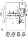
- An in FIG. 1 illustrated electro-hydraulic safety system 2 or auxiliary system comprises a pressure supply device 6 and a reservoir 10 for brake fluid. Via a hydraulic line 12, the pressure-providing device 6 can be connected to at least one brake circuit. In the hydraulic line 12, an electrically actuated isolation valve 14 is connected. By means of a redundant pressure sensor 18, the pressure present in the hydraulic line 12 can be measured.
- the pressure-providing device 6 comprises one by an electromechanical actuator comprising an electric motor 26, the rotor position of which is determined by a redundantly designed rotor position sensor 30 which detects the angle of the rotor.
- the rotation of the rotor is converted into the axial movement of a piston 36 by a rotation-translation gear, which is in the present case designed as a ball screw.
- the piston 36 is displaced into a pressure chamber 42 of the pressure supply device 6.
- the pressure chamber 42 is constructed in a stepped manner and comprises a first sub-chamber 46 and a second sub-chamber 52 adjoining it.
- the piston 36 is moved in a stroke direction 62 and first dives into the first sub-chamber 46 and then into the second sub-travel Part chamber 52 a.
- a sealing element 60 is provided, which seals in a submerged state of the piston 36 in the second sub-chamber, the first sub-chamber 46 and the second sub-chamber 52 against each other.
- Both sub-chambers 46, 52 and the piston 36 have a substantially round cross-section, wherein the cross section of the second sub-chamber 52 is smaller than the cross-section of the first sub-chamber 46.
- the piston 36 is constructed in two stages with a first stage 38, the outer cross-section of which corresponds to the inner cross-section of the first sub-chamber 46 and an adjoining second stage 40 whose outer cross-section corresponds to the inner cross-section of the second sub-chamber 52.
- the safety system 2 is preferably used in a brake-by-wire brake system in which brake pressure is actively built up by the pressure supply device 6.
- the brake system has two front wheel brakes 64, 68 and two rear wheel brakes 72, 76.
- the safety system 2 is suitable, in particular for automated driving, even in the event of failure of a check valve between the pressure supply device 6 and reservoir 10 to continue to allow active pressure buildup by means of the pressure supply device 6.
- a check valve between the pressure supply device 6 and reservoir 10 to continue to allow active pressure buildup by means of the pressure supply device 6.
- a relatively long delay is to be expected before the driver can actively brake in case of failure of the active pressure build-up in a fallback in case of malfunction.
- a fallback level with active pressure is provided, so that active pressure build-up is possible even if a check valve fails.
- first hydraulic reservoir line 80 Via a first hydraulic reservoir line 80, the first sub-chamber 46 is connected to the reservoir 10.
- a first check valve 84 In the reservoir line 80, a first check valve 84 is connected, the blocking side is connected to the reservoir 10.
- the check valve 84 is a normally closed (SG) auxiliary valve or connecting valve 88 connected in parallel, which is mechanically switched.
- the connecting valve 88 is disposed in an auxiliary hydraulic line 92, which in a node 96 branches off from the reservoir line 80 and opens at a node 100 back into this.
- a second hydraulic reservoir line 104 branches from at a junction of the conduit 12 and terminates at a junction 114 into the first reservoir conduit 80.
- a second check valve 120 Connected to the second hydraulic reservoir conduit 104 is a second check valve 120 whose blocking side is hydraulically connected to the suction side of the first check valve 84 is.
- one of the two check valves 84, 120 fails.
- hydraulic pressure can no longer be built up in the first sub-chamber 46.
- the brake system does not have to switch to a hydraulic fallback mode in which the driver builds brake pressure with muscle power when the brake pedal is actuated.
- pressure can build up again in the second sub-chamber - assuming the functioning of the second check valve 120.
- FIG. 2 a security system 2 is shown in a second preferred embodiment.
- the SG auxiliary valve 88 is electrically connected in response to a signal of the pressure sensor 18 and / or the engine position sensor 30th
- the function of the two check valves 84, 120 can be checked as follows.
- the tightness of the second check valve 120 is - preferably cyclically - tested by the piston 36 with the aid of the electric motor 30 is presented so far until the division of the pressure chamber 42 in two sub-chambers 46, 52 has occurred.
- the tightness of the first check valve can be checked.
- the tightness of the first check valve 84 is checked each time the hydraulic piston 36 is actuated.
Landscapes
- Engineering & Computer Science (AREA)
- Transportation (AREA)
- Mechanical Engineering (AREA)
- Physics & Mathematics (AREA)
- Fluid Mechanics (AREA)
- Valves And Accessory Devices For Braking Systems (AREA)
- Regulating Braking Force (AREA)
Description
- Die Erfindung betrifft ein hydraulisches Sicherheitssystem für eine elektrohydraulische Bremsanlage. Sie betrifft weiterhin eine Bremsanlage mit einem derartigen Sicherheitssystem. Sie betrifft weiterhin ein Verfahren zum Betreiben einer derartigen Bremsanlage.
- In der Kraftfahrzeugtechnik finden "Brake-by-Wire"-Bremsanlagen eine immer größere Verbreitung. Derartige Bremsanlagen umfassen oftmals neben einem durch den Fahrzeugführer betätigbaren Hauptbremszylinder eine elektrisch ("by-Wire") ansteuerbare Druckbereitstellungseinrichtung, mittels welcher in der Betriebsart "Brake-by-Wire" eine Betätigung der Radbremsen stattfindet.
- Bei diesen modernen Bremssystemen, insbesondere elektrohydraulischen Bremssystemen mit der Betriebsart "Brake-by-Wire", ist der Fahrer von dem direkten Zugriff auf die Bremsen entkoppelt. Bei Betätigung des Pedals werden gewöhnlich eine Pedalentkopplungseinheit und ein Simulator betätigt, wobei durch eine Sensorik der Bremswunsch des Fahrers erfasst wird. Der gewöhnlich als Hauptbremszylinder ausgebildete Pedalsimulator dient dazu, dem Fahrer ein möglichst vertrautes und komfortables Bremspedalgefühl zu vermitteln. Der erfasste Bremswunsch führt zu der Bestimmung eines Sollbremsmomentes, woraus dann der Sollbremsdruck für die Bremsen ermittelt wird. Der Bremsdruck wird dann aktiv von einer Druckbereitstellungseinrichtung in den Bremsen aufgebaut. Das tatsächliche Bremsen erfolgt also durch aktiven Druckaufbau in den Bremskreisen mit Hilfe einer Druckbereitstellungseinrichtung, die von einer Steuer- und Regeleinheit angesteuert wird. Durch die hydraulische Entkopplung der Bremspedalbetätigung von dem Druckaufbau lassen sich in derartigen Bremssystemen viele Funktionalitäten wie ABS, ESC, TCS, Hanganfahrhilfe etc. für den Fahrer komfortabel verwirklichen.
- In derartigen Bremssystemen ist gewöhnlich eine hydraulische Rückfallebene vorgesehen, durch die der Fahrer durch Muskelkraft bei Betätigung des Bremspedals das Fahrzeug abbremsen bzw. zum Stehen bringen kann, wenn die "By-Wire"-Betriebsart ausfällt oder gestört ist. Während im Normalbetrieb durch eine Pedalentkopplungseinheit die oben beschriebene hydraulische Entkopplung zwischen Bremspedalbetätigung und Bremsdruckaufbau erfolgt, wird in der Rückfallebene diese Entkopplung aufgehoben, so dass der Fahrer direkt Bremsmittel in die Bremskreise verschieben kann.
- Die Druckbereitstellungseinrichtung in oben beschriebenen Bremssystemen wird auch als Aktuator bzw. hydraulischer Aktuator bezeichnet. Insbesondere werden Aktuatoren als Linearaktuatoren bzw. Lineareinheiten ausgebildet, bei denen zum Druckaufbau ein Kolben axial in einen hydraulischen Druckraum verschoben wird, der in Reihe mit einem Rotations-Translationsgetriebe gebaut ist.
- Aus der
WO 2011/029812 A1 ist eine "Brake-by-Wire"-Bremsanlage mit einem bremspedalbetätigbaren Hauptbremszylinder, einem Wegsimulator und einer Druckbereitstellungseinrichtung bekannt. Die Radbremsen werden in einer "Brake-by-Wire"-Betriebsart durch die Druckbereitstellungseinrichtung mit Druck beaufschlagt. In einer Rückfallbetriebsart werden die Radbremsen mittels des mit dem Bremspedal betätigbaren Hauptbremszylinders mit Druck beaufschlagt. - Aus der
DE 10 2013 216 423 A1 ist eine Bremsanlage mit einer hydraulischen Druckbereitstellungseinrichtung mit einem zweistufigen Druckraum mit einer ersten und einem zweiten Teilkammer bekannt, wobei nur ein Rückschlagventil vorgesehen ist, welches zwischen der ersten Teilkammer und dem Reservoir hydraulisch angeordnet ist. - Zum Nachsaugen von Bremsflüssigkeit ist bei bekannten Bremsanlagen gewöhnlich die Druckbereitstellungseinrichtung über eine hydraulische Leitung, in die ein Rückschlagventil geschaltet ist, mit einem Reservoir verbunden. Die Sperrseite des Rückschlagventils ist mit dem Reservoir und die Saugseite des Rückschlagventils mit der Druckbereitstellungseinrichtung hydraulisch verbunden.
- In die Rückfallebene wird geschaltet, wenn mit Hilfe der Druckbereitstellungseinrichtung kein Druckaufbau mehr möglich ist. Dies ist u. a. dann der Fall, wenn das Rückschlagventil, welches die Druckbereitstellungseinrichtung mit dem Reservoir verbindet, nicht mehr zuverlässig sperrt, so dass ein Druckaufbau nicht mehr zuverlässig möglich ist.
- Beim automatisierten Fahren, bei dem das Fahrzeug autonom fährt, muss davon ausgegangen werden, dass der Fahrer über einen längeren Zeitraum nicht in der Lage ist, bei Ausfall dieses Rückschlagventils eine Bremsung in der Rückfalleben durchzuführen.
- Der Erfindung liegt daher die Aufgabe zugrunde, auch bei Ausfall des Rückschlagventils noch aktive Bremsungen mit Hilfe der Druckbereitstellungseinrichtung zu ermöglichen.
- In Bezug auf das hydraulische Sicherheitssystem wird diese Aufgabe erfindungsgemäß gelöst mit einer hydraulischen Druckbereitstellungseinrichtung mit einem Druckraum, der über wenigstens ein Trennventil mit wenigstens einem Bremskreis verbindbar ist und in den zum Druckaufbau ein Kolben verschoben wird, und einem Reservoir für Bremsflüssigkeit, wobei der Druckraum zweistufig ausgebildet ist mit einer ersten Teilkammer und einer zweiten Teilkammer, wobei beim Druckaufbau der Kolben zunächst in die erste und dann die zweite Teilkammer verschoben wird, wobei die beiden Kammer hydraulisch gegeneinander abgeschlossen sind, wenn der Kolben einen vorgegebenen Weg in die zweite Teilkammer verschoben ist, und wobei ein erstes Rückschlagventil mit seiner Saugseite an der ersten Teilkammer und mit seiner Sperrseite an dem Reservoir hydraulisch angeschlossen, und wobei ein zweites Rückschlagventil mit seiner Saugseite an der zweiten Teilkammer angeschlossen ist, und wobei die Sperrseite des zweiten Rückschlagventils mit der Saugseite des ersten Rückschlagventils verbunden ist.
- Vorteilhafte Ausgestaltungen sind Gegenstand der Unteransprüche.
- Die Erfindung geht von der Überlegung aus, dass für das ordnungsgemäße Funktionieren einer Bremsanlage, die in der "Brake-by-Wire"-Betriebsart betrieben wird, essentiell wichtig ist, dass die Druckbereitstellungseinrichtung jederzeit bedarfsweise Bremsdruck aufbauen kann. Damit stets genügend Bremsflüssigkeit vorhanden ist, muss sie bedarfsweise aus dem Reservoir Bremsflüssigkeit nachsaugen können. Ein Rückschlagventil muss in der entsprechenden hydraulischen Leitung, die zum Nachsaugen verwendet wird, zuverlässig verhindern, dass beim Druckaufbau nicht Bremsmittel durch diese Leitung zurück in das Reservoir fließt. Fällt das Rückschlagventil teilweise oder vollständig aus bzw. kann es diese Aufgabe nicht mehr erfüllen, muss gewöhnlich in die Rückfallebene geschaltet werden, in der der Fahrer direkten Zugriff auf die Radbremsen erhält und mit Muskelkraft Bremsdruck aufbauen kann.
- Bei diesem Umschalten kann aber in gefährlichen Situationen wertvolle Zeit verstreichen, da der Fahrer erkennen muss, dass er nun stärker als zuvor das Bremspedal betätigen muss und sich Bremspedalweg und Pedalgefühl geändert haben. Insofern wäre es wünschenswert, dass auch nach Ausfall des Rückschlagventils noch aktiver Druckaufbau möglich wäre.
- Wie nunmehr erkannt wurde, lässt sich dies realisieren, indem der Druckraum zweiteilig aufgebaut ist mit zwei Teilkammern, von denen jeweils eine hydraulische Leitung zu dem Reservoir führt, wobei nach einem vorgegebenen Verfahrweg des Kolbens die beiden Kammern hydraulisch gegeneinander abgedichtet sind, und wobei in jeder der beiden Leitungen ein Rückschlagventil geschaltet ist mit der Besonderheit, dass die Sperrseite des einen Rückschlagventils mit der Saugseite des anderen Rückschlagventils verbunden ist. Diese Konstruktion erlaubt den aktiven Druckaufbau durch die Druckbereitstellungseinrichtung auch dann, wenn eines der beiden Ventile ausgefallen ist, so dass nicht unmittelbar in die herkömmliche Rückfallebene geschaltet werden muss. Auf diese Weise wird gewissermaßen eine aktive Rückfallebene bzw. Zwischenrückfallebene bereitgestellt.
- Vorteilhafterweise ist ein Dichtelement vorgesehen, welches in einem eingetauchten Zustand des Kolbens in der zweiten Teilkammer die erste Teilkammer und die zweite Teilkammer gegeneinander hydraulisch abdichtet. Das Dichtelement ist vorzugsweise im Bereich der zweiten Kammer befestigt.
- Der Querschnitt der zweiten Teilkammer ist vorzugsweise geringer als der Querschnitt der ersten Teilkammer. Der Kolben der Druckbereitstellungseinrichtung ist bei einer derartigen Ausführung bevorzugt als Stufenkolben ausgebildet, mit einer ersten Stufe, deren Querschnitt dem der ersten Teilkammer entspricht und einer daran sich anschließenden zweiten Stufe, deren Querschnitt dem der zweiten Teilkammer entspricht und die in die zweite Teilkammer eintaucht.
- Die erste Teilkammer ist vorzugsweise durch eine hydraulische Leitung mit dem Reservoir verbunden ist, in die ein Verbindungsventil bzw. Hilfsventil geschaltet ist.
- Das Verbindungsventil ist bevorzugt elektrisch schaltbar. Alternativ kann das Verbindungsventil auch hydraulisch schaltbar ausgebildet sein.
- In Bezug auf die Bremsanlage wird die oben genannte Aufgabe erfindungsgemäß gelöst mit einem mittels eines Bremspedals betätigbaren Hauptbremszylinders, dessen mindestens einer Druckraum mit Bremskreisen zugeordneten Radbremsen, insbesondere trennbar, verbunden ist, mit einer Druckregelventilanordnung zur Regelung und/oder Steuerung eines an einer Radbremse eingesteuerten Radbremsdruckes, mit einem oben beschriebenen hydraulischen Sicherheitssystem und mit einer elektronischen Steuer- und Regeleinheit zur Ansteuerung der Druckbereitstellungseinrichtung des Sicherheitssystems und/oder der Druckventilanordnung.
- In Bezug auf das Verfahren wird die oben genannte Aufgabe erfindungsgemäß gelöst indem, bevorzugt zyklisch, die Dichtheit des ersten Rückschlagventils überprüft wird, indem der Kolben in die zweite Teilkammer gefahren wird, bis die beiden Teilkammern hydraulisch getrennt sind, und wobei das Verbindungsventil geöffnet wird und der Druck in der die Druckbereitstellungseinrichtung mit dem wenigstens einen Bremskreis verbindenden Leitung und/oder die Stromaufnahme eines Elektromotors der Druckbereitstellungseinrichtung überwacht wird.
- Vorteilhafterweise wird beim Verfahren des Kolbens die Dichtigkeit des zweiten Rückschlagventils überprüft, indem der in der hydraulischen Kammer eingestellte Druck (in der Regel bei jeder Betätigung)beobachtet wird. Bei Druckabbau ohne weitere Kolbenbewegung kann von einer Leckage ausgegangen werden.
- Bei Erkennen des Ausfalls beider Rückschlagventile wird vorteilhafterweise in eine hydraulische Rückfallebene geschaltet, wobei die Druckbereitstellungseinrichtung von den Bremskreisen hydraulisch getrennt wird und der Hautbremszylinder mit den Bremskreisen hydraulisch verbunden wird.
- Die Vorteile der Erfindung liegen insbesondere darin, dass durch ein beschriebenes Hilfssystem eine zusätzliche Rückfallebene bereitgestellt ist, in der noch aktiver Druckaufbau möglich ist, wodurch die Sicherheit des Fahrers vergrößert wird, da dieser nicht sofort aktiv Bremsdruck durch Muskelkraft aufbauen muss. Damit kann insbesondere in kritischen Situationen das Fahrzeug schnell abgebremst werden, da nicht die Reaktionszeit des Fahrers verstreicht. Dies ist insbesondere beim automatisierten Fahren vorteilhaft aber auch bei von dem Fahrer aktiv gesteuerten Fahrzeugen mit einer elektrohydraulischen Bremsanlage, die im Brake-by-Wire-Betrieb betrieben wird.
- Ein Ausführungsbeispiel der Erfindung wird anhand einer Zeichnung näher erläutert. Darin zeigen in stark schematisierter Darstellung:
- FIG. 1
- ein hydraulisches Sicherheitssystem in einer ersten bevorzugten Ausführung, und
- FIG. 2
- ein hydraulisches Sicherheitssystem in einer zweiten bevorzugten Ausführung.
- Gleiche Teile sind in beiden Figuren mit denselben Bezugszeichen versehen.
- Ein in
FIG. 1 dargestelltes elektrohydraulisches Sicherheitssystem 2 bzw. Hilfssystem umfasst eine Druckbereitstellungseinrichtung 6 und ein Reservoir 10 für Bremsflüssigkeit. Über eine hydraulische Leitung 12 ist die Druckbereitstellungseinrichtung 6 mit wenigstens einem Bremskreis verbindbar. In die hydraulische Leitung 12 ist ein elektrisch betätigbares Trennventil 14 geschaltet. Mittels eines redundant ausgeführten Drucksensors 18 kann der in der hydraulischen Leitung 12 vorliegende Druck gemessen werden. - Die Druckbereitstellungseinrichtung 6 umfasst einen durch einen elektromechanischen Aktuator, der einen Elektromotor 26 umfasst, dessen Rotorlage durch einen redundant ausgeführten Rotorlagesensor 30, der den Winkel des Rotors erfasst, bestimmt wird. Die Rotation des Rotors wird durch ein Rotations-Translations-Getriebe, welches vorliegend als Kugelgewindetrieb ausgebildet ist, in die axiale Bewegung eines Kolbens 36 umgewandelt. Zum aktiven Druckaufbau wird der Kolben 36 in einen Druckraum 42 der Druckbereitstellungseinrichtung 6 verschoben. Der Druckraum 42 ist gestuft aufgebaut und umfasst eine erste Teilkammer 46 und eine sich darin anschließende zweite Teilkammer 52. Zum Druckaufbau wird der Kolben 36 in einer Hubrichtung 62 verfahren und taucht dabei zunächst in die erste Teilkammer 46 und dann nach einem weiteren Verfahrweg in die zweite Teilkammer 52 ein. In der zweiten Teilkammer 52 ist ein Dichtelement 60 vorgesehen, welches in einem eingetauchten Zustand des Kolbens 36 in die zweite Teilkammer die erste Teilkammer 46 und die zweite Teilkammer 52 gegeneinander abdichtet. Beide Teilkammern 46, 52 sowie der Kolben 36 haben im Wesentlichen einen runden Querschnitt, wobei der Querschnitt der zweiten Teilkammer 52 kleiner ist als der Querschnitt der ersten Teilkammer 46. Der Kolben 36 ist zweistufig aufgebaut mit einer ersten Stufe 38, deren Außenquerschnitt dem Innenquerschnitt der ersten Teilkammer 46 entspricht und einer sich daran anschließenden zweiten Stufe 40, deren Außenquerschnitt dem Innenquerschnitt der zweiten Teilkammer 52 entspricht. Auf diese Weise kann beim Verfahren des Kolbens 36 in Hubrichtung 62 zunächst Bremsflüssigkeit aus der ersten Teilkammer 36 und, sobald der Kolben 36 in die zweite Teilkammer 52 eintaucht, aus der zweiten Teilkammer 52 verdrängt werden, was zu einem Druckaufbau in den Radbremsen 64, 68, 72, 76 führt.
- Das Sicherheitssystem 2 wird bevorzugt in einer Brake-by-Wire-Bremsanlage eingesetzt, bei der durch die Druckbereitstellungseinrichtung 6 aktiv Bremsdruck aufgebaut wird. Die Bremsanlage weist dabei vorliegend zwei Vorderradbremsen 64, 68 und zwei Hinterradbremsen 72, 76 auf.
- Das Sicherheitssystem 2 ist geeignet, insbesondere beim automatisierten Fahren, auch bei Ausfall eines Rückschlagventils zwischen Druckbereitstellungseinrichtung 6 und Reservoir 10 noch weiterhin aktiven Druckaufbau mit Hilfe der Druckbereitstellungseinrichtung 6 zu ermöglichen. Bei Fahrzeugen, die weitgehend autonom fahren und bei denen der Fahrer nicht aktiv steuert ist eine relativ lange Verzögerung zu erwarten, bevor der Fahrer bei einem Ausfall des aktiven Druckaufbaus in einer Rückfallebene bei einer Fehlfunktion aktiv eine Bremsung durchführen kann. Aber auch bei nicht-automatischem Fahren ergeben sich dadurch Vorteile, dass gewissermaßen eine Rückfallebene mit aktivem Druck vorgesehen ist, so dass aktiver Druckaufbau auch bei Ausfall eines Rückschlagventils möglich ist.
- Über eine erste hydraulische Reservoirleitung 80 ist die erste Teilkammer 46 mit dem Reservoir 10 verbunden. In die Reservoirleitung 80 ist ein erstes Rückschlagventil 84 geschaltet, dessen Sperrseite mit dem Reservoir 10 verbunden ist. Dem Rückschlagventil 84 ist ein stromlos geschlossenes (SG) Hilfsventil bzw. Verbindungsventil 88 parallel geschaltet, welches mechanisch geschaltet wird. Das Verbindungsventil 88 ist in einer hydraulischen Hilfsleitung 92 angeordnet, welche in einem Knotenpunkt 96 von der Reservoirleitung 80 abzweigt und in einem Knotenpunkt 100 wieder in diese mündet.
- Eine zweite hydraulische Reservoirleitung 104 verzweigt von an einem Knotenpunkt von der Leitung 12 und mündet in einem Knotenpunkt 114 in die erste Reservoirleitung 80. In die zweite hydraulische Reservoirleitung 104 ist ein zweites Rückschlagventil 120 geschaltet, dessen Sperrseite mit der Saugseite des ersten Rückschlagventils 84 hydraulisch verbunden ist.
- Im Folgenden werden zwei Szenarien diskutiert, bei denen jeweils eines der beiden Rückschlagventile 84, 120 ausfällt. Wenn das erste Rückschlagventil 84 ausfällt, kann in der ersten Teilkammer 46 kein hydraulischer Druck mehr aufgebaut werden. Die Bremsanlage muss aber nicht in eine hydraulische Rückfallebene schalten, bei der der Fahrer bei Betätigung des Bremspedals mit Muskelkraft Bremsdruck aufbaut. Sobald der Kolben 36 in die zweite Teilkammer 52 eintaucht, die von der ersten Teilkammer durch das Dichtelement 60, welches in der zweiten Teilkammer 5 angeordnet, abgedichtet wird, kann in der zweiten Teilkammer wieder Druck aufgebaut - das Funktionieren des zweiten Rückschlagventils 120 vorausgesetzt.
- Fällt das zweite Rückschlagventil 120 aus, d. h. sperrt es nicht mehr den Fluss von Bremsflüssigkeit aus der Druckbereitstellungseinrichtung 6 in das Reservoir 10, kann trotzdem Druck aufgebaut werden, wenn sich der Kolben 36 in der ersten 46 oder der zweiten Teilkammer 52 befindet, da die Sperrseite des zweiten Rückschlagventils 120 mit der Saugseite des ersten Rückschlagventils 84 verbunden ist über die Leitungen 104 und 80.
- Fällt also eines der beiden Rückschlagventile 84, 120 aus, ist somit noch weiterhin aktiver Druckaufbau möglich. Nur in dem sehr unwahrscheinlichen Fall, dass beide Rückschlagventile 84, 120 ausfallen, muss in die hydraulische Rückfallebene geschaltet werden.
- In
FIG. 2 ist ein Sicherheitssystem 2 in einer zweiten bevorzugten Ausführung dargestellt. Bei dem inFIG. 2 dargestellten Sicherheitssystem 2 wird das SG Hilfsventil 88 elektrisch geschaltet in Abhängigkeit von einem Signal des Drucksensors 18 und/oder des Motorpositionssensors 30. - Die Funktion der beiden Rückschlagventile 84, 120 kann wie folgt geprüft werden. Die Dichtheit des zweiten Rückschlagventils 120 wird - bevorzugt zyklisch - geprüft, indem der Kolben 36 mit Hilfe des Elektromotors 30 soweit vorgestellt wird, bis die Teilung des Druckraums 42 in zwei Teilkammern 46, 52 erfolgt ist. Dann kann nach Öffnen des Verbindungsventils bzw. Hilfsventils 88 mit Hilfe des Drucksensors 18 oder anhand der Motorstromaufnahme die Dichtheit des ersten Rückschlagventils überprüft werden. Die Dichtheit des ersten Rückschlagventils 84 wird bei jeder Betätigung des hydraulischen Kolbens 36 überprüft.
-
- 2
- Sicherheitssystem
- 6
- Druckbereitstellungseinrichtung
- 10
- Reservoir
- 12
- hydraulische Leitung
- 14
- elektrisch betätigbares Trennventil
- 18
- Drucksensor
- 26
- Elektromotor
- 30
- Rotorlagesensor
- 36
- Kolben
- 42
- Druckraum
- 46
- erste Teilkammer
- 52
- zweite Teilkammer
- 60
- Dichtelement
- 62
- Hubrichtung
- 64, 68
- Vorderradbremsen
- 72, 76
- Hinterradbremsen
- 80
- hydraulische Reservoirleitung
- 84
- erstes Rückschlagventil
- 88
- stromlos geschlossenes (SG) Hilfs- bzw. Verbindungsventil
- 92
- Hilfsleitung
- 96
- Knotenpunkt
- 100
- Knotenpunkt
- 104
- hydraulische Reservoirleitung
- 114
- Knotenpunkt
- 120
- zweites Rückschlagventil
Claims (11)
- Hydraulisches Sicherheitssystem (2) für eine elektrohydraulische Bremsanlage, mit einer hydraulischen Druckbereitstellungseinrichtung (6) mit einem Druckraum (42), der über wenigstens ein Trennventil (14) mit wenigstens einem Bremskreis verbindbar ist und in den zum Druckaufbau ein Kolben (36) verschoben wird, und einem Reservoir (10) für Bremsflüssigkeit, wobei der Druckraum (42) zweistufig ausgebildet ist mit einer ersten Teilkammer (46) und einer zweiten Teilkammer (52), wobei beim Druckaufbau der Kolben (36) zunächst in die erste (46) und dann die zweite Teilkammer (52) verschoben wird, wobei die beiden Teilkammern (46, 52) hydraulisch gegeneinander abgeschlossen sind, wenn der Kolben (36) einen vorgegebenen Weg in die zweite Teilkammer (52) verschoben ist, und wobei ein erstes Rückschlagventil (84) mit seiner Saugseite an der ersten Teilkammer (46) und mit seiner Sperrseite an dem Reservoir (10) hydraulisch angeschlossen ist, dadurch gekennzeichnet, dass ein zweites Rückschlagventil (120) mit seiner Saugseite an der zweiten Teilkammer (52) angeschlossen ist, und die Sperrseite des zweiten Rückschlagventils (120) mit der Saugseite des ersten Rückschlagventils (84) verbunden ist.
- Hydraulisches Sicherheitssystem (2) nach Anspruch 1, wobei ein Dichtelement (60) vorgesehen ist, welches in einem eingetauchten Zustand des Kolbens (36) in der zweiten Teilkammer (52) die erste Teilkammer (46) und die zweite Teilkammer (52) gegeneinander hydraulisch abdichtet.
- Hydraulisches Sicherheitssystem (2) nach Anspruch 1 oder 2, wobei der Querschnitt der zweiten Teilkammer (52) geringer ist als der Querschnitt der ersten Teilkammer (46).
- Hydraulisches Sicherheitssystem (2) nach einem der Ansprüche 1 bis 3, wobei die erste Teilkammer (46) durch eine hydraulische Leitung (80) mit dem Reservoir (10) verbunden ist, in die ein Verbindungsventil (88) geschaltet ist.
- Hydraulisches Sicherheitssystem (2) nach Anspruch 4, wobei das Verbindungsventil (88) elektrisch schaltbar ist.
- Hydraulisches Sicherheitssystem (2) nach Anspruch 4 oder 5, wobei das Verbindungsventil (88) mechanisch oder hydraulisch schaltbar ist.
- Bremsanlage mit einem mittels eines Bremspedals betätigbaren Hauptbremszylinders, dessen mindestens einer Druckraum mit Bremskreisen zugeordneten Radbremsen (64, 68, 72, 76), insbesondere trennbar, verbunden ist, mit einer Druckregelventilanordnung zur Regelung und/oder Steuerung eines an einer Radbremse (64, 68, 72, 76) eingesteuerten Radbremsdruckes, mit einem hydraulischen Sicherheitssystem (2) nach einem der Ansprüche 1 bis 6 und mit einer elektronischen Steuer- und Regeleinheit zur Ansteuerung der Druckbereitstellungseinrichtung (6) des Sicherheitssystems (2) und/oder der Druckventilanordnung.
- Verfahren zum Betreiben einer Bremsanlage nach Anspruch 7, wobei die Dichtheit des ersten Rückschlagventils (84) überprüft wird, indem der Kolben (36) in die zweite Teilkammer (52) gefahren wird, bis die beiden Teilkammern (46, 52) hydraulisch getrennt sind, und wobei das Verbindungsventil (88) geöffnet wird und der Druck in einer die Druckbereitstellungseinrichtung (6) mit dem wenigstens einen Bremskreis verbindenden Leitung (12) und/oder die Stromaufnahme eines Elektromotors (26) der Druckbereitstellungseinrichtung (6) überwacht wird.
- Verfahren zum Betreiben einer Bremsanlage nach Anspruch 8, wobei die Dichtheit des ersten Rückschlagventils (84) zyklisch überprüft wird.
- Verfahren zum Betreiben einer Bremsanlage nach Anspruch 8 oder 9, wobei, im Wesentlichen jedes Mal, beim Verfahren des Kolbens (36) die Dichtigkeit des zweiten Rückschlagventils (120) überprüft wird.
- Verfahren zum Betreiben einer Bremsanlage nach Anspruch 10, wobei bei Erkennen des Ausfalls beider Rückschlagventile (84, 120) in eine hydraulische Rückfallebene geschaltet wird, wobei die Druckbereitstellungseinrichtung (6) von den Bremskreisen hydraulisch getrennt wird und der Hautbremszylinder mit den Bremskreisen hydraulisch verbunden wird.
Applications Claiming Priority (2)
| Application Number | Priority Date | Filing Date | Title |
|---|---|---|---|
| DE102014220432.1A DE102014220432A1 (de) | 2014-10-09 | 2014-10-09 | Hydraulisches Sicherheitssystem, Bremsanlage und Betriebsverfahren |
| PCT/EP2015/072678 WO2016055343A1 (de) | 2014-10-09 | 2015-10-01 | Hydraulisches sicherheitssystem, bremsanlage und betriebsverfahren |
Publications (2)
| Publication Number | Publication Date |
|---|---|
| EP3204271A1 EP3204271A1 (de) | 2017-08-16 |
| EP3204271B1 true EP3204271B1 (de) | 2018-06-27 |
Family
ID=54207522
Family Applications (1)
| Application Number | Title | Priority Date | Filing Date |
|---|---|---|---|
| EP15771610.1A Not-in-force EP3204271B1 (de) | 2014-10-09 | 2015-10-01 | Hydraulisches sicherheitssystem, bremsanlage und betriebsverfahren |
Country Status (5)
| Country | Link |
|---|---|
| US (1) | US10683000B2 (de) |
| EP (1) | EP3204271B1 (de) |
| KR (1) | KR101950616B1 (de) |
| DE (1) | DE102014220432A1 (de) |
| WO (1) | WO2016055343A1 (de) |
Cited By (1)
| Publication number | Priority date | Publication date | Assignee | Title |
|---|---|---|---|---|
| DE102021125284A1 (de) | 2021-09-29 | 2023-03-30 | Zf Active Safety Gmbh | Hydraulische Anordnung, Diagnoseverfahren und Bremssystem |
Families Citing this family (15)
| Publication number | Priority date | Publication date | Assignee | Title |
|---|---|---|---|---|
| DE102015223508A1 (de) * | 2015-11-27 | 2017-06-01 | Robert Bosch Gmbh | Pumpenaggregat für eine hydraulische Fahrzeugbremsanlage |
| DE102017113563A1 (de) * | 2017-06-20 | 2018-12-20 | Ipgate Ag | Bremssystem |
| KR102469183B1 (ko) * | 2017-10-26 | 2022-11-23 | 에이치엘만도 주식회사 | 전자식 브레이크 시스템 및 그 제어 방법 |
| KR102421448B1 (ko) * | 2017-10-27 | 2022-07-18 | 주식회사 만도 | 전자식 브레이크 시스템 및 제어 방법 |
| DE102017219920A1 (de) * | 2017-11-09 | 2019-05-09 | Robert Bosch Gmbh | elektrohydraulischer Bremsaktor |
| KR102068995B1 (ko) * | 2018-03-08 | 2020-02-11 | 주식회사 만도 | 전자식 브레이크 시스템 및 그 제어방법 |
| KR102514965B1 (ko) * | 2018-05-03 | 2023-03-28 | 에이치엘만도 주식회사 | 전자식 브레이크 시스템 및 제어 방법 |
| WO2019215030A1 (de) | 2018-05-09 | 2019-11-14 | Ipgate Ag | Bremssystem |
| JP7458141B2 (ja) * | 2018-05-22 | 2024-03-29 | ヤンマーパワーテクノロジー株式会社 | 作業車両 |
| DE102018212284A1 (de) | 2018-07-24 | 2020-01-30 | Robert Bosch Gmbh | Verfahren zum Betreiben eines Bremssystems sowie Bremssystem |
| CN113631443B (zh) * | 2019-02-12 | 2024-02-23 | 爱皮加特股份公司 | 具有压力供给装置和用于制动回路的安全门的制动系统 |
| US11052886B2 (en) | 2019-09-20 | 2021-07-06 | Caterpillar Inc. | Hydraulic brake system with make-up line |
| DE102021207277A1 (de) * | 2021-07-09 | 2023-01-12 | Continental Automotive Technologies GmbH | Bremssystem für ein Kraftfahrzeug |
| CN113335259B (zh) * | 2021-07-22 | 2022-06-21 | 中国第一汽车股份有限公司 | 制动系统上电检测方法、装置、设备和存储介质 |
| DE102021208783A1 (de) * | 2021-08-11 | 2023-02-16 | Robert Bosch Gesellschaft mit beschränkter Haftung | Verfahren zum Entlüften eines Zylinders einer Kolben-Zylinder-Einheit eines Fremdkraft-Bremsdruckerzeugers einer hydraulischen Fremdkraft-Bremsanlage |
Family Cites Families (20)
| Publication number | Priority date | Publication date | Assignee | Title |
|---|---|---|---|---|
| DE4310061A1 (de) * | 1993-03-27 | 1994-09-29 | Teves Gmbh Alfred | Hydraulische Bremsanlage mit Schlupfregelung |
| EP0742766B1 (de) * | 1994-01-20 | 1998-05-27 | ITT Automotive Europe GmbH | Hydraulische bremsanlage mit schlupfregelung |
| DE19538794A1 (de) * | 1995-10-18 | 1997-04-24 | Teves Gmbh Alfred | Elektronisch regelbares Bremsbetätigungssystem |
| DE19626926B4 (de) * | 1996-07-04 | 2006-03-16 | Continental Teves Ag & Co. Ohg | Elektronisch regelbares Bremsbetätigungssystem |
| US6082831A (en) * | 1998-04-22 | 2000-07-04 | General Motors Corporation | Electro-hydraulic brake apply system displacement augmentation |
| US6604795B2 (en) * | 2000-12-28 | 2003-08-12 | Toyota Jidosha Kabushiki Kaisha | Braking system including high-pressure source between master cylinder and brake cylinder |
| JP4654547B2 (ja) * | 2001-07-24 | 2011-03-23 | トヨタ自動車株式会社 | ブレーキ装置 |
| KR101392626B1 (ko) | 2005-07-18 | 2014-05-07 | 톰슨 라이센싱 | 다중 비디오 스트림 핸들링 방법 |
| US8177309B2 (en) * | 2008-05-02 | 2012-05-15 | GM Global Technology Operations LLC | Braking booster system leak diagnostics |
| DE102010040097A1 (de) | 2009-09-11 | 2011-03-31 | Continental Teves Ag & Co. Ohg | Bremsanlage für Kraftfahrzeuge |
| DE102011081461A1 (de) * | 2010-08-30 | 2012-03-01 | Continental Teves Ag & Co. Ohg | Bremsanlage für Kraftfahrzeuge |
| DE102011122776A1 (de) * | 2011-07-21 | 2013-01-24 | Daimler Ag | Bremsanlage für ein Kraftfahrzeug |
| DE102012212836A1 (de) * | 2011-08-17 | 2013-02-21 | Continental Teves Ag & Co. Ohg | Bremsanlage für Kraftfahrzeuge |
| DE102012219996A1 (de) * | 2012-11-01 | 2014-05-08 | Continental Teves Ag & Co. Ohg | Vorrichtung und Verfahren zur digitalen Übertragung eines Signals |
| DE102013216423A1 (de) * | 2013-03-05 | 2014-09-11 | Continental Teves Ag & Co. Ohg | Druckbereitstellungseinrichtung und Bremsanlage |
| DE102013224870A1 (de) * | 2013-03-05 | 2014-09-11 | Continental Teves Ag & Co. Ohg | Bremsbetätigungseinheit |
| US10940843B2 (en) * | 2013-03-15 | 2021-03-09 | ZF Active Safety US Inc. | Vehicle brake system having plunger power source |
| DE102014205431A1 (de) * | 2013-03-28 | 2014-10-02 | Robert Bosch Gmbh | Bremssystem für ein Fahrzeug |
| EP3145771B1 (de) * | 2014-05-20 | 2018-11-07 | IPGate AG | Betätigungssystem für eine fahrzeugbremse und verfahren zum betrieb des betätigungssystems |
| DE102015106089A1 (de) * | 2015-04-21 | 2016-10-27 | Ipgate Ag | Diagnoseverfahren für ein Bremssystem |
-
2014
- 2014-10-09 DE DE102014220432.1A patent/DE102014220432A1/de not_active Withdrawn
-
2015
- 2015-10-01 KR KR1020177008929A patent/KR101950616B1/ko not_active Expired - Fee Related
- 2015-10-01 WO PCT/EP2015/072678 patent/WO2016055343A1/de not_active Ceased
- 2015-10-01 EP EP15771610.1A patent/EP3204271B1/de not_active Not-in-force
-
2017
- 2017-04-10 US US15/483,533 patent/US10683000B2/en not_active Expired - Fee Related
Non-Patent Citations (1)
| Title |
|---|
| None * |
Cited By (1)
| Publication number | Priority date | Publication date | Assignee | Title |
|---|---|---|---|---|
| DE102021125284A1 (de) | 2021-09-29 | 2023-03-30 | Zf Active Safety Gmbh | Hydraulische Anordnung, Diagnoseverfahren und Bremssystem |
Also Published As
| Publication number | Publication date |
|---|---|
| WO2016055343A1 (de) | 2016-04-14 |
| US10683000B2 (en) | 2020-06-16 |
| KR20170046787A (ko) | 2017-05-02 |
| DE102014220432A1 (de) | 2016-04-14 |
| KR101950616B1 (ko) | 2019-05-31 |
| US20170210372A1 (en) | 2017-07-27 |
| EP3204271A1 (de) | 2017-08-16 |
Similar Documents
| Publication | Publication Date | Title |
|---|---|---|
| EP3204271B1 (de) | Hydraulisches sicherheitssystem, bremsanlage und betriebsverfahren | |
| EP3419876B1 (de) | Zusatzmodul für eine elektrohydraulische bremsanlage und bremsanlagensystem mit einem derartigen zusatzmodul | |
| EP4251483B1 (de) | Verfahren zur steuerung einer bremsanlage und bremsanlage für kraftfahrzeuge | |
| EP3356191B1 (de) | Bremssystem und verfahren zum betreiben eines bremssystems | |
| EP3558771B1 (de) | Bremssystem mit zwei druckquellen und zwei verfahren zum betreiben eines bremssystems | |
| EP2964499B1 (de) | Bremsbetätigungseinheit | |
| EP2964497B1 (de) | Druckbereitstellungseinrichtung und bremsanlage | |
| EP3568329B1 (de) | Verfahren zum betreiben einer bremsanlage und bremsanlage | |
| EP2731836B1 (de) | Sicherheitsschaltung für blockierenden antrieb eines bremskraftverstärkers | |
| DE102011079454A1 (de) | Elektrohydraulisches Bremssystem vom Typ Brake-by-Wire und zugehöriges Betriebsverfahren | |
| EP3036135A1 (de) | Bremsanlage für kraftfahrzeuge | |
| WO2018091311A1 (de) | Bremsanlage und verfahren zum betreiben einer bremsanlage | |
| DE102011085273A1 (de) | Bremsanlage für Kraftfahrzeuge | |
| DE102017211955A1 (de) | Bremssystem mit einem Zusatzmodul | |
| DE102017210078A1 (de) | Bremsanlage und Verfahren zu deren Betrieb | |
| DE102016202224A1 (de) | Verfahren zum Betreiben einer Bremsanlage eines Fahrzeuges und Bremsanlage | |
| EP1917169B1 (de) | Verfahren und vorrichtung zum betrieb einer hydraulischen fahrzeugbremsanlage | |
| DE102016208564B4 (de) | Verfahren zum Betreiben einer Bremsanlage mit einer Druckbereitstellungseinrichtung und Bremsanlage | |
| WO2018172060A1 (de) | Verfahren zum betreiben eines bremssystems und bremssystem | |
| DE102016220752A1 (de) | Verfahren zum Betreiben eines Bremssystems und Bremssystem | |
| DE102017211807A1 (de) | Bremssystem mit primärer Bremsregeleinrichtung und Zusatzmodul | |
| DE102017209758A1 (de) | Bremssystem und Verfahren zum Betreiben eines Bremssystems | |
| DE102019215288A1 (de) | Verfahren zur Steuerung einer elektronisch schlupfregelbaren Fremdkraftbremsanlage, insbesondere für ein Kraftfahrzeug und elektronisch schlupfregelbaren Fremdkraftbremsanlage, insbesondere für ein Kraftfahrzeug | |
| EP3356193B1 (de) | Bremsgerät für eine hydraulische kraftfahrzeugbremsanlage | |
| WO2018184845A1 (de) | Bremssystem |
Legal Events
| Date | Code | Title | Description |
|---|---|---|---|
| PUAI | Public reference made under article 153(3) epc to a published international application that has entered the european phase |
Free format text: ORIGINAL CODE: 0009012 |
|
| 17P | Request for examination filed |
Effective date: 20170509 |
|
| AK | Designated contracting states |
Kind code of ref document: A1 Designated state(s): AL AT BE BG CH CY CZ DE DK EE ES FI FR GB GR HR HU IE IS IT LI LT LU LV MC MK MT NL NO PL PT RO RS SE SI SK SM TR |
|
| AX | Request for extension of the european patent |
Extension state: BA ME |
|
| DAV | Request for validation of the european patent (deleted) | ||
| DAX | Request for extension of the european patent (deleted) | ||
| GRAP | Despatch of communication of intention to grant a patent |
Free format text: ORIGINAL CODE: EPIDOSNIGR1 |
|
| INTG | Intention to grant announced |
Effective date: 20180213 |
|
| GRAS | Grant fee paid |
Free format text: ORIGINAL CODE: EPIDOSNIGR3 |
|
| GRAA | (expected) grant |
Free format text: ORIGINAL CODE: 0009210 |
|
| AK | Designated contracting states |
Kind code of ref document: B1 Designated state(s): AL AT BE BG CH CY CZ DE DK EE ES FI FR GB GR HR HU IE IS IT LI LT LU LV MC MK MT NL NO PL PT RO RS SE SI SK SM TR |
|
| REG | Reference to a national code |
Ref country code: GB Ref legal event code: FG4D Free format text: NOT ENGLISH |
|
| REG | Reference to a national code |
Ref country code: AT Ref legal event code: REF Ref document number: 1012021 Country of ref document: AT Kind code of ref document: T Effective date: 20180715 |
|
| REG | Reference to a national code |
Ref country code: IE Ref legal event code: FG4D Free format text: LANGUAGE OF EP DOCUMENT: GERMAN |
|
| REG | Reference to a national code |
Ref country code: DE Ref legal event code: R096 Ref document number: 502015004871 Country of ref document: DE |
|
| RAP2 | Party data changed (patent owner data changed or rights of a patent transferred) |
Owner name: CONTINENTAL TEVES AG & CO. OHG |
|
| PG25 | Lapsed in a contracting state [announced via postgrant information from national office to epo] |
Ref country code: NO Free format text: LAPSE BECAUSE OF FAILURE TO SUBMIT A TRANSLATION OF THE DESCRIPTION OR TO PAY THE FEE WITHIN THE PRESCRIBED TIME-LIMIT Effective date: 20180927 Ref country code: FI Free format text: LAPSE BECAUSE OF FAILURE TO SUBMIT A TRANSLATION OF THE DESCRIPTION OR TO PAY THE FEE WITHIN THE PRESCRIBED TIME-LIMIT Effective date: 20180627 Ref country code: LT Free format text: LAPSE BECAUSE OF FAILURE TO SUBMIT A TRANSLATION OF THE DESCRIPTION OR TO PAY THE FEE WITHIN THE PRESCRIBED TIME-LIMIT Effective date: 20180627 Ref country code: BG Free format text: LAPSE BECAUSE OF FAILURE TO SUBMIT A TRANSLATION OF THE DESCRIPTION OR TO PAY THE FEE WITHIN THE PRESCRIBED TIME-LIMIT Effective date: 20180927 Ref country code: SE Free format text: LAPSE BECAUSE OF FAILURE TO SUBMIT A TRANSLATION OF THE DESCRIPTION OR TO PAY THE FEE WITHIN THE PRESCRIBED TIME-LIMIT Effective date: 20180627 |
|
| REG | Reference to a national code |
Ref country code: NL Ref legal event code: MP Effective date: 20180627 |
|
| REG | Reference to a national code |
Ref country code: LT Ref legal event code: MG4D |
|
| PG25 | Lapsed in a contracting state [announced via postgrant information from national office to epo] |
Ref country code: LV Free format text: LAPSE BECAUSE OF FAILURE TO SUBMIT A TRANSLATION OF THE DESCRIPTION OR TO PAY THE FEE WITHIN THE PRESCRIBED TIME-LIMIT Effective date: 20180627 Ref country code: HR Free format text: LAPSE BECAUSE OF FAILURE TO SUBMIT A TRANSLATION OF THE DESCRIPTION OR TO PAY THE FEE WITHIN THE PRESCRIBED TIME-LIMIT Effective date: 20180627 Ref country code: GR Free format text: LAPSE BECAUSE OF FAILURE TO SUBMIT A TRANSLATION OF THE DESCRIPTION OR TO PAY THE FEE WITHIN THE PRESCRIBED TIME-LIMIT Effective date: 20180928 Ref country code: RS Free format text: LAPSE BECAUSE OF FAILURE TO SUBMIT A TRANSLATION OF THE DESCRIPTION OR TO PAY THE FEE WITHIN THE PRESCRIBED TIME-LIMIT Effective date: 20180627 |
|
| PG25 | Lapsed in a contracting state [announced via postgrant information from national office to epo] |
Ref country code: NL Free format text: LAPSE BECAUSE OF FAILURE TO SUBMIT A TRANSLATION OF THE DESCRIPTION OR TO PAY THE FEE WITHIN THE PRESCRIBED TIME-LIMIT Effective date: 20180627 |
|
| PG25 | Lapsed in a contracting state [announced via postgrant information from national office to epo] |
Ref country code: IS Free format text: LAPSE BECAUSE OF FAILURE TO SUBMIT A TRANSLATION OF THE DESCRIPTION OR TO PAY THE FEE WITHIN THE PRESCRIBED TIME-LIMIT Effective date: 20181027 Ref country code: PL Free format text: LAPSE BECAUSE OF FAILURE TO SUBMIT A TRANSLATION OF THE DESCRIPTION OR TO PAY THE FEE WITHIN THE PRESCRIBED TIME-LIMIT Effective date: 20180627 Ref country code: EE Free format text: LAPSE BECAUSE OF FAILURE TO SUBMIT A TRANSLATION OF THE DESCRIPTION OR TO PAY THE FEE WITHIN THE PRESCRIBED TIME-LIMIT Effective date: 20180627 Ref country code: RO Free format text: LAPSE BECAUSE OF FAILURE TO SUBMIT A TRANSLATION OF THE DESCRIPTION OR TO PAY THE FEE WITHIN THE PRESCRIBED TIME-LIMIT Effective date: 20180627 Ref country code: CZ Free format text: LAPSE BECAUSE OF FAILURE TO SUBMIT A TRANSLATION OF THE DESCRIPTION OR TO PAY THE FEE WITHIN THE PRESCRIBED TIME-LIMIT Effective date: 20180627 Ref country code: SK Free format text: LAPSE BECAUSE OF FAILURE TO SUBMIT A TRANSLATION OF THE DESCRIPTION OR TO PAY THE FEE WITHIN THE PRESCRIBED TIME-LIMIT Effective date: 20180627 |
|
| PG25 | Lapsed in a contracting state [announced via postgrant information from national office to epo] |
Ref country code: ES Free format text: LAPSE BECAUSE OF FAILURE TO SUBMIT A TRANSLATION OF THE DESCRIPTION OR TO PAY THE FEE WITHIN THE PRESCRIBED TIME-LIMIT Effective date: 20180627 Ref country code: SM Free format text: LAPSE BECAUSE OF FAILURE TO SUBMIT A TRANSLATION OF THE DESCRIPTION OR TO PAY THE FEE WITHIN THE PRESCRIBED TIME-LIMIT Effective date: 20180627 Ref country code: IT Free format text: LAPSE BECAUSE OF FAILURE TO SUBMIT A TRANSLATION OF THE DESCRIPTION OR TO PAY THE FEE WITHIN THE PRESCRIBED TIME-LIMIT Effective date: 20180627 |
|
| REG | Reference to a national code |
Ref country code: DE Ref legal event code: R097 Ref document number: 502015004871 Country of ref document: DE |
|
| PLBE | No opposition filed within time limit |
Free format text: ORIGINAL CODE: 0009261 |
|
| STAA | Information on the status of an ep patent application or granted ep patent |
Free format text: STATUS: NO OPPOSITION FILED WITHIN TIME LIMIT |
|
| PG25 | Lapsed in a contracting state [announced via postgrant information from national office to epo] |
Ref country code: DK Free format text: LAPSE BECAUSE OF FAILURE TO SUBMIT A TRANSLATION OF THE DESCRIPTION OR TO PAY THE FEE WITHIN THE PRESCRIBED TIME-LIMIT Effective date: 20180627 |
|
| REG | Reference to a national code |
Ref country code: CH Ref legal event code: PL |
|
| 26N | No opposition filed |
Effective date: 20190328 |
|
| REG | Reference to a national code |
Ref country code: BE Ref legal event code: MM Effective date: 20181031 |
|
| PG25 | Lapsed in a contracting state [announced via postgrant information from national office to epo] |
Ref country code: LU Free format text: LAPSE BECAUSE OF NON-PAYMENT OF DUE FEES Effective date: 20181001 Ref country code: MC Free format text: LAPSE BECAUSE OF FAILURE TO SUBMIT A TRANSLATION OF THE DESCRIPTION OR TO PAY THE FEE WITHIN THE PRESCRIBED TIME-LIMIT Effective date: 20180627 |
|
| REG | Reference to a national code |
Ref country code: IE Ref legal event code: MM4A |
|
| PG25 | Lapsed in a contracting state [announced via postgrant information from national office to epo] |
Ref country code: BE Free format text: LAPSE BECAUSE OF NON-PAYMENT OF DUE FEES Effective date: 20181031 Ref country code: SI Free format text: LAPSE BECAUSE OF FAILURE TO SUBMIT A TRANSLATION OF THE DESCRIPTION OR TO PAY THE FEE WITHIN THE PRESCRIBED TIME-LIMIT Effective date: 20180627 Ref country code: CH Free format text: LAPSE BECAUSE OF NON-PAYMENT OF DUE FEES Effective date: 20181031 Ref country code: FR Free format text: LAPSE BECAUSE OF NON-PAYMENT OF DUE FEES Effective date: 20181031 Ref country code: LI Free format text: LAPSE BECAUSE OF NON-PAYMENT OF DUE FEES Effective date: 20181031 |
|
| PG25 | Lapsed in a contracting state [announced via postgrant information from national office to epo] |
Ref country code: IE Free format text: LAPSE BECAUSE OF NON-PAYMENT OF DUE FEES Effective date: 20181001 |
|
| PG25 | Lapsed in a contracting state [announced via postgrant information from national office to epo] |
Ref country code: AL Free format text: LAPSE BECAUSE OF FAILURE TO SUBMIT A TRANSLATION OF THE DESCRIPTION OR TO PAY THE FEE WITHIN THE PRESCRIBED TIME-LIMIT Effective date: 20180627 |
|
| PG25 | Lapsed in a contracting state [announced via postgrant information from national office to epo] |
Ref country code: MT Free format text: LAPSE BECAUSE OF FAILURE TO SUBMIT A TRANSLATION OF THE DESCRIPTION OR TO PAY THE FEE WITHIN THE PRESCRIBED TIME-LIMIT Effective date: 20180627 |
|
| PG25 | Lapsed in a contracting state [announced via postgrant information from national office to epo] |
Ref country code: TR Free format text: LAPSE BECAUSE OF FAILURE TO SUBMIT A TRANSLATION OF THE DESCRIPTION OR TO PAY THE FEE WITHIN THE PRESCRIBED TIME-LIMIT Effective date: 20180627 |
|
| PG25 | Lapsed in a contracting state [announced via postgrant information from national office to epo] |
Ref country code: PT Free format text: LAPSE BECAUSE OF FAILURE TO SUBMIT A TRANSLATION OF THE DESCRIPTION OR TO PAY THE FEE WITHIN THE PRESCRIBED TIME-LIMIT Effective date: 20180627 |
|
| PG25 | Lapsed in a contracting state [announced via postgrant information from national office to epo] |
Ref country code: HU Free format text: LAPSE BECAUSE OF FAILURE TO SUBMIT A TRANSLATION OF THE DESCRIPTION OR TO PAY THE FEE WITHIN THE PRESCRIBED TIME-LIMIT; INVALID AB INITIO Effective date: 20151001 Ref country code: CY Free format text: LAPSE BECAUSE OF FAILURE TO SUBMIT A TRANSLATION OF THE DESCRIPTION OR TO PAY THE FEE WITHIN THE PRESCRIBED TIME-LIMIT Effective date: 20180627 Ref country code: MK Free format text: LAPSE BECAUSE OF NON-PAYMENT OF DUE FEES Effective date: 20180627 |
|
| GBPC | Gb: european patent ceased through non-payment of renewal fee |
Effective date: 20191001 |
|
| PG25 | Lapsed in a contracting state [announced via postgrant information from national office to epo] |
Ref country code: GB Free format text: LAPSE BECAUSE OF NON-PAYMENT OF DUE FEES Effective date: 20191001 |
|
| REG | Reference to a national code |
Ref country code: AT Ref legal event code: MM01 Ref document number: 1012021 Country of ref document: AT Kind code of ref document: T Effective date: 20201001 |
|
| PG25 | Lapsed in a contracting state [announced via postgrant information from national office to epo] |
Ref country code: AT Free format text: LAPSE BECAUSE OF NON-PAYMENT OF DUE FEES Effective date: 20201001 |
|
| REG | Reference to a national code |
Ref country code: DE Ref legal event code: R081 Ref document number: 502015004871 Country of ref document: DE Owner name: CONTINENTAL AUTOMOTIVE TECHNOLOGIES GMBH, DE Free format text: FORMER OWNER: CONTINENTAL TEVES AG & CO. OHG, 60488 FRANKFURT, DE |
|
| PGFP | Annual fee paid to national office [announced via postgrant information from national office to epo] |
Ref country code: DE Payment date: 20220421 Year of fee payment: 8 |
|
| REG | Reference to a national code |
Ref country code: DE Ref legal event code: R119 Ref document number: 502015004871 Country of ref document: DE |
|
| PG25 | Lapsed in a contracting state [announced via postgrant information from national office to epo] |
Ref country code: DE Free format text: LAPSE BECAUSE OF NON-PAYMENT OF DUE FEES Effective date: 20240501 |