EP3204482B2 - Lebensmitteltechnische prozessanlage, insbesondere brauereianlage mit blockheizkraft - Google Patents
Lebensmitteltechnische prozessanlage, insbesondere brauereianlage mit blockheizkraft Download PDFInfo
- Publication number
- EP3204482B2 EP3204482B2 EP15784586.8A EP15784586A EP3204482B2 EP 3204482 B2 EP3204482 B2 EP 3204482B2 EP 15784586 A EP15784586 A EP 15784586A EP 3204482 B2 EP3204482 B2 EP 3204482B2
- Authority
- EP
- European Patent Office
- Prior art keywords
- heat
- heat exchanger
- cooling
- transfer medium
- temperature
- Prior art date
- Legal status (The legal status is an assumption and is not a legal conclusion. Google has not performed a legal analysis and makes no representation as to the accuracy of the status listed.)
- Active
Links
Images
Classifications
-
- C—CHEMISTRY; METALLURGY
- C12—BIOCHEMISTRY; BEER; SPIRITS; WINE; VINEGAR; MICROBIOLOGY; ENZYMOLOGY; MUTATION OR GENETIC ENGINEERING
- C12C—BEER; PREPARATION OF BEER BY FERMENTATION; PREPARATION OF MALT FOR MAKING BEER; PREPARATION OF HOPS FOR MAKING BEER
- C12C13/00—Brewing devices, not covered by a single group of C12C1/00 - C12C12/04
-
- F—MECHANICAL ENGINEERING; LIGHTING; HEATING; WEAPONS; BLASTING
- F02—COMBUSTION ENGINES; HOT-GAS OR COMBUSTION-PRODUCT ENGINE PLANTS
- F02G—HOT GAS OR COMBUSTION-PRODUCT POSITIVE-DISPLACEMENT ENGINE PLANTS; USE OF WASTE HEAT OF COMBUSTION ENGINES; NOT OTHERWISE PROVIDED FOR
- F02G5/00—Profiting from waste heat of combustion engines, not otherwise provided for
- F02G5/02—Profiting from waste heat of exhaust gases
- F02G5/04—Profiting from waste heat of exhaust gases in combination with other waste heat from combustion engines
-
- F—MECHANICAL ENGINEERING; LIGHTING; HEATING; WEAPONS; BLASTING
- F02—COMBUSTION ENGINES; HOT-GAS OR COMBUSTION-PRODUCT ENGINE PLANTS
- F02G—HOT GAS OR COMBUSTION-PRODUCT POSITIVE-DISPLACEMENT ENGINE PLANTS; USE OF WASTE HEAT OF COMBUSTION ENGINES; NOT OTHERWISE PROVIDED FOR
- F02G2260/00—Recuperating heat from exhaust gases of combustion engines and heat from cooling circuits
-
- F—MECHANICAL ENGINEERING; LIGHTING; HEATING; WEAPONS; BLASTING
- F02—COMBUSTION ENGINES; HOT-GAS OR COMBUSTION-PRODUCT ENGINE PLANTS
- F02G—HOT GAS OR COMBUSTION-PRODUCT POSITIVE-DISPLACEMENT ENGINE PLANTS; USE OF WASTE HEAT OF COMBUSTION ENGINES; NOT OTHERWISE PROVIDED FOR
- F02G2262/00—Recuperating heat from exhaust gases of combustion engines and heat from lubrication circuits
-
- Y—GENERAL TAGGING OF NEW TECHNOLOGICAL DEVELOPMENTS; GENERAL TAGGING OF CROSS-SECTIONAL TECHNOLOGIES SPANNING OVER SEVERAL SECTIONS OF THE IPC; TECHNICAL SUBJECTS COVERED BY FORMER USPC CROSS-REFERENCE ART COLLECTIONS [XRACs] AND DIGESTS
- Y02—TECHNOLOGIES OR APPLICATIONS FOR MITIGATION OR ADAPTATION AGAINST CLIMATE CHANGE
- Y02E—REDUCTION OF GREENHOUSE GAS [GHG] EMISSIONS, RELATED TO ENERGY GENERATION, TRANSMISSION OR DISTRIBUTION
- Y02E20/00—Combustion technologies with mitigation potential
- Y02E20/14—Combined heat and power generation [CHP]
-
- Y—GENERAL TAGGING OF NEW TECHNOLOGICAL DEVELOPMENTS; GENERAL TAGGING OF CROSS-SECTIONAL TECHNOLOGIES SPANNING OVER SEVERAL SECTIONS OF THE IPC; TECHNICAL SUBJECTS COVERED BY FORMER USPC CROSS-REFERENCE ART COLLECTIONS [XRACs] AND DIGESTS
- Y02—TECHNOLOGIES OR APPLICATIONS FOR MITIGATION OR ADAPTATION AGAINST CLIMATE CHANGE
- Y02T—CLIMATE CHANGE MITIGATION TECHNOLOGIES RELATED TO TRANSPORTATION
- Y02T10/00—Road transport of goods or passengers
- Y02T10/10—Internal combustion engine [ICE] based vehicles
- Y02T10/12—Improving ICE efficiencies
Definitions
- the invention relates to a food processing plant, in particular a brewery plant, and a method for energy-optimized supply of a food processing plant according to the preambles of claims 1 and 8.
- DE 20 2008 014 330 U1 describes a device for supplying energy to a brewery, where there is an exhaust gas heat exchanger circuit and a separate engine heat exchanger circuit, which are connected in parallel to one another and flow into a common heat storage unit.
- This document does not show that there are at least three heat exchangers connected in series, via which a heat transfer medium is heated by waste heat from the block-type power plant, and also does not show that this heat transfer medium is heated via the at least three heat exchangers connected in series and has a temperature of more than 100 °C.
- the DE 10 2009 013 579 A1 describes a brewery plant for producing and bottling beer, where a bottle cleaning system, a bottle pasteurisation system and the ZIP cleaning system are heated by an energy generation system above a combined heat and power plant. This document also does not describe a series connection of three heat exchangers that are heated to more than 100 °C by waste heat from the combined heat and power plant.
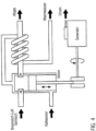
- Fig. 4 shows, for example, a schematic diagram of a corresponding combined heat and power plant, which here includes an example of a combustion engine and a power generator, so that the mechanical work generated by combustion can be converted into electrical energy.
- a drive motor must be cooled.
- hot water can be generated using a heat exchanger from the waste heat of the engine and the exhaust gas.
- combined heat and power plants with turbochargers are used.
- the gas which is heated up considerably during compression, must be cooled down to around 30° to 50°C in order to prevent engine damage and to ensure safe and efficient operation of the CHP plant.
- the engine cooling water which is around 80° to 90°C, can be used to extract the first part of this heat, but in order to cool the heated gas further to 30° to 50°C, large air coolers are often used and the remaining heat is discharged outside.
- several heat exchangers are used to cool the combined heat and power plant. For example, a heat exchanger for cooling the engine oil, a heat exchanger for cooling the coolant for the engine block and a heat exchanger for cooling the exhaust gas from the combined heat and power plant.
- the heat transfer medium which is then intended to heat the various heat consumers, for example in the brewery, is only heated to a maximum temperature of around 92° to 96°C.
- this temperature of the heat transfer medium is too low for energy-optimized and extensive use in breweries.
- much higher temperatures of 100° to over 110°C are required, particularly for heating mashing devices or wort kettles, for example.
- not all of the engine waste heat has been extracted from the engine in the form of high-pressure hot water or steam and fed into a circuit to heat heat consumers.
- a bottle washing machine usually has internal tube bundle heat exchangers installed that are located in the lye and heat it up without additional pumping energy (on the lye side). Steam or high-pressure hot water with temperatures between 130° and 160°C is normally used as the heat transfer medium. If the heat transfer medium is now reduced in temperature to, for example, 95°C, as provided by a combined heat and power plant, then the driving force Delta Theta is reduced and either the K value of the heat exchanger must be increased significantly (for example with an external flow) or the heat exchanger surface. Both can only be achieved with great effort in a bottle washing machine. Systems that are heated at such a low temperature therefore usually have an additional external heat exchanger for heating the lye or a corresponding one must be retrofitted. Of course, this requires an additional pump and system components to pump the lye through the external heat exchanger and heat it up. Corresponding solutions are costly and complex.
- a combined heat and power plant should always run at full load in order to work economically and cover as much of the electricity demand as possible, for example of a brewery.
- combined heat and power plants are usually designed in such a way that they can cover the base load heat flow of a bottle washing machine and can or must also generate hot water if necessary because they cannot continuously dissipate the waste heat. If the bottle washing machine stops, however, either the combined heat and power plant must be turned down or switched off, or the excess heat must be temporarily stored and used later. In any case, it is very difficult to cover the full energy demand of a bottle washing machine with a combined heat and power plant. to provide because it cannot be operated continuously and smaller and larger stops, different bottle sizes or cleaning speeds of the bottle washing machine cause different heat flows.
- Such load fluctuations could of course also be compensated by producing hot water.
- hot water In brewhouses and breweries, however, there is usually too much hot water during the production week because, for example, it is produced in large quantities after each brew during wort production (e.g. wort cooling). If additional hot water is produced, ie water in a temperature range of 75°C to 85°C, this excess water is temporarily stored in large tanks and often used for weekend or larger tank cleanings.
- the heating medium which has a temperature in the range of around 95°C
- an absorption refrigeration system produces cold from heat.
- a COP of 0.5 for example, 100 kW of heat flow from a combined heat and power plant can produce around 50 kW of cold flow with a temperature of -5°C.
- To provide 50 kW of cold with a compression refrigeration machine with a COP of 4 for example, far less than 15 kW of electrical energy is needed compared to an absorption refrigeration machine.
- the waste heat from a combined heat and power plant is also used, if possible, for sensible heating in the brewery's production.
- the difficulty with using combined heat and power plants is the heat transfer medium return temperature (to the CHP plant). This means that the heat transfer medium that was heated by the combined heat and power plant and cooled by heating different heat consumers should normally not exceed 78° to 80°C when fed back into the combined heat and power plant, so that sufficient cooling of the combined heat and power plant is guaranteed.
- the return temperature is less than or equal to 80°C.
- Some heating devices can only provide a return temperature of around 85°C or 90°C because the medium to be heated must already be heated to 80°C to 85°C or tempered to this temperature (e.g. wort boiling or pasteurization).
- the resulting higher return temperatures increase the risk of damaging the cogeneration plant.
- cogeneration plant manufacturers usually do not allow higher return temperatures for cooling the cogeneration plant than around 80°C. The energy-optimized and extensive use of cogeneration plants, especially in breweries, is therefore difficult.
- the warm-up phase of a cogeneration plant takes time, and even after a longer shutdown, a high load cannot be called up immediately (whether electrical or thermal). In addition, the cogeneration plant consumes fuel during this time that is not converted into useful work. If a cogeneration plant runs below nominal load before reaching its operating temperature, this can lead to engine damage or at least to much greater wear.
- the object of the present invention is to provide a process plant, in particular a brewery plant, as well as a method for the energy-optimized supply of such a plant by means of a combined heat and power plant.
- the heat transfer medium via which at least one heat consumer of the food processing plant is supplied with heat energy, is heated by waste heat from the cogeneration plant via at least three heat exchangers connected in series on the cogeneration plant.
- the cogeneration plant can thus heat a heat transfer medium to high temperatures in a simple manner.
- very high heat transfer medium temperatures of over 100°C and even over 110°C (up to 115°C) (in particular from at least 80% of the engine waste heat) can be achieved.
- a heat transfer medium with such high temperatures is particularly suitable for the heat consumers in a brewery that require correspondingly high temperatures.
- the high heating medium temperatures can therefore also be used to partially or even completely supply the wort boiling in the brewhouse process.
- the thermal energy can therefore be used sensibly in the brewhouse and other areas of the brewery, thereby replacing primary energy.
- the heat transfer medium heated to the high temperatures is therefore particularly suitable for bottle washing machines with internal heat exchangers that have limited heating surface reserves, and absorption refrigeration systems would also achieve higher COPs with higher drive temperatures.
- a suitably heated heat transfer medium can be fed into an energy storage tank, in particular a pressure storage tank, and is available to the heat consumers when required.
- the returns from such "high-temperature consumers” in a low-temperature brewery) can then be used a second time in other "low-temperature consumers", for example, so that the heat transfer medium can cool down to a low temperature, for example 80°C.
- High-temperature consumers are consumers that require heat transfer medium with a temperature > 100°C at normal pressure.
- Food processing plants include, for example, brewery plants, plants for the production and bottling of beverages such as wine, spirits, juices, water, soft drinks, tea or grain-based beverages, plants for the production and bottling of liquid foods such as dairy products, (edible) oils, (soy) sauce, concentrate production, e.g. syrups for the food and beverage industry, as well as the associated cleaning systems, such as CIP and other cleaning systems, etc.
- beverages such as wine, spirits, juices, water, soft drinks, tea or grain-based beverages
- plants for the production and bottling of liquid foods such as dairy products, (edible) oils, (soy) sauce
- concentrate production e.g. syrups for the food and beverage industry, as well as the associated cleaning systems, such as CIP and other cleaning systems, etc.
- the at least three heat exchangers connected in series are heat exchangers from the following group: heat exchanger WT1 for cooling engine oil of the combined heat and power plant, heat exchanger WT2 for cooling cooling medium for the engine block of the combined heat and power plant, heat exchanger WT3 for cooling the exhaust gas of the combined heat and power plant and heat exchanger WT4a for cooling a compressed intake gas of the combined heat and power plant.
- the heat exchanger WT1 for cooling the engine oil is advantageously located in front of the other heat exchangers in the flow direction of the heat transfer medium.
- the second heat exchanger for cooling the cooling medium for the engine block is arranged downstream of the first heat exchanger for cooling the engine oil and the third heat exchanger for cooling the exhaust gas is arranged as the last heat exchanger - because then the heat transfer medium in the second heat exchanger still has a sufficiently low temperature to sufficiently cool the cooling medium or cooling water for the engine block.
- the exhaust gas has a relatively high temperature in a range of up to 500°C, a large amount of heat can be released here and at the same time the heat transfer medium can be heated to higher temperatures.
- This heat exchanger is advantageously arranged last after the second heat exchanger.
- the cooling of the exhaust gas is not critical because inadequate cooling cannot cause engine damage.
- a further heat exchanger is provided which is connected in series to the previously mentioned heat exchangers.
- a heat exchanger for cooling a compressed intake gas of the cogeneration plant is arranged in particular after the first and before the third heat exchanger, advantageously between the second heat exchanger and the third heat exchanger.
- this heat exchanger is connected in series with the heat exchangers mentioned above, this allows the heat transfer medium to be brought to an even higher temperature, e.g. up to 115°C.
- the thermal energy that is generated by cooling a compressed intake gas that is produced when using a turbocharger was not used in this way in the prior art and thus serves effectively to increase the heat transfer medium temperature.
- Well over 30 kW of thermal energy can be dissipated into the heat transfer medium at this heat exchanger, for example at full load of a CHP plant with 400 kW of electrical energy production.
- the heat transfer medium which is heated by the at least three heat exchangers connected in series, is fed via an energy storage tank, in particular a pressure storage tank, or directly to at least one heat consumer in the process plant, and the cooled heat transfer medium is returned directly or via the energy storage tank to the combined heat and power plant for cooling.
- the heat transfer medium can also be usefully fed through several heat consumers in a circuit K and release its energy.
- any excess heat flow that is not immediately used can be stored and temporarily stored in the same energy storage unit. This means that the cogeneration plant can always be operated within its design range, or at least for longer, and at the same time, peak loads that are above the nominal heat flow of the cogeneration plant can be covered by the energy storage unit. Only when the storage tank reaches a predetermined filling level does the cogeneration plant have to be turned down or, if necessary, switched off completely later.
- heat energy with temperatures > 100°C can also be stored in a corresponding energy storage tank, in particular a pressure storage tank, and a precisely desired heat transfer medium temperature can be achieved, for example by removing it from one or more specific points in the case of a stratified storage tank and/or by using a mixer, whereby this heat transfer medium can then be fed to the heat consumer(s) and returned to the cycle.
- a precisely desired heat transfer medium temperature can be achieved, for example by removing it from one or more specific points in the case of a stratified storage tank and/or by using a mixer, whereby this heat transfer medium can then be fed to the heat consumer(s) and returned to the cycle.
- the heat exchanger for cooling the engine oil Before the circulating heat transfer medium is fed again to the first heat exchanger WT1, ie the heat exchanger for cooling the engine oil, it can be cooled or adjusted to an appropriate temperature in advance if it has a temperature that is too high, for example > 80°C.
- a further heat exchanger is provided for this purpose, which can cool the heat carrier to a predetermined temperature, preferably in a range of 75°C to 80°C °C. This ensures that the cogeneration plant is always sufficiently cooled so that no damage occurs.
- the heat exchanger for cooling the compressed intake gas is connected in series with the other heat exchangers and heats up the (external) heat carrier (which is connected to the energy storage device), it is no longer necessary, as was often the case in the prior art, for the amount of heat that drops off in this heat exchanger to be fed to a cooling medium for cooling the engine block, and so the temperature of the cooling medium for the engine block of the cogeneration plant has a lower temperature. For this reason, the inlet temperature of the external heat carrier that is circulated before it is returned to the first heat exchanger WT1 can have a higher temperature than in comparable circuits in the prior art.
- the temperature of the heat carrier when it is fed to the first heat exchanger WT1 for cooling the engine oil to have a temperature in a range of > 80°C to 83°C or even > 80°C to 85°C.
- the return temperature of the heat transfer medium in circuit K corresponds to a predetermined temperature T 1 or is in a predetermined temperature range, it is not necessary to cool the returning heat transfer medium via the additional heat exchanger.
- a bypass is advantageously provided which directs either the returning heat transfer medium and/or the cooling medium which cools the returning heat transfer medium past the heat exchanger WT5 which cools the returning heat transfer medium. This makes it possible to react to fluctuating return temperatures of the heat transfer medium.
- the cogeneration plant has a heat exchanger for cooling the compressed intake gas between a compressor and an engine of the cogeneration plant and in particular a second heat exchanger for cooling the pre-cooled compressed intake gas of the cogeneration plant, which is located downstream of the heat exchanger for cooling the compressed intake gas.
- this low-temperature heat is released via the roof, but this residual heat of the compressed intake gas can still be used specifically, for example in a brewery, whereby it must be ensured that the temperature of the air-fuel mixture is sufficiently low before it enters the engine or combustion chamber.
- the second heat exchanger for cooling the intake gas advantageously has an inlet for a cooling medium, in particular for cold water, and an outlet for the heated cooling medium, whereby the heated cooling medium can then be fed as a cooling medium to the inlet of the heat exchanger WT5, which cools the heat transfer medium returned in the circuit.
- Such a connection is particularly advantageous in terms of energy because the required temperatures at the CHP are maintained and at the same time as little energy as possible is lost to the environment.
- a heat transfer medium is heated by a combined heat and power plant to supply heat consumers of the food processing plant.
- the heat transfer medium is heated by at least three heat exchangers connected in series, the complete waste heat of the combined heat and power plant (e.g. from engine oil, cooling water, compression heat and exhaust gas) to a temperature of at least 100 °C, advantageously at least 110 °C.
- the heat transfer medium in a first heat exchanger WT1 in particular for cooling the engine oil of the combined heat and power plant, is heated from a temperature T 1 in a range of 75°C to 80°C to a temperature T 2 which corresponds to the heat and volume flow, whereby this will advantageously be 2°C to 3°C below the maximum oil temperature which may emerge from the engine.
- the temperature T 1 may be somewhat higher, ie in a range of e.g. > 80°C to 83°C or > 80°C to 85°C.
- the heat transfer medium can be heated in a second heat exchanger to cool the cooling medium for the engine block of the combined heat and power plant and then with the third Heat exchanger for cooling the exhaust gas to a temperature T 4 > 100°C, preferably 110°C. It is also possible that, according to a further embodiment, after the first heat exchanger WT1, but preferably after the second heat exchanger WT2, the heat transfer medium is further heated by a heat exchanger WT4a for cooling a compressed intake gas of the cogeneration plant, i.e. between a compressor and an internal combustion engine, and then by the third heat exchanger to the temperature T 4 , which can be up to 5°C above the temperature T 4 that is generated when the further heat exchanger is not used.
- the heat transfer medium is circulated and, in particular after it has been heated by the at least three heat exchangers to a temperature T 4 > 100°C, in particular > 110°C, is fed via an energy storage tank, in particular a pressure storage tank, or directly to at least one heat consumer.
- the heat transfer medium cooled directly or in several stages is returned to the combined heat and power plant for cooling, either directly or via the energy storage tank.
- the energy storage tank is advantageously a stratified storage tank, whereby the heat transfer medium is taken from the stratified storage tank at a predetermined temperature and/or is taken at one or more locations and/or is brought to the predetermined temperature using a mixer. This enables an exact temperature to be achieved for the heat consumers.
- the heat transfer medium Before it is returned to the first heat exchanger, in particular the heat exchanger for cooling engine oil, the heat transfer medium can be cooled via a further heat exchanger WT5 to a temperature T 1 in a range from 75°C to 80°C or to a temperature > 80°C to 83°C or > 80°C to 85°C.
- the heat transfer medium preferably from the energy storage tank, can be fed to the cogeneration plant at a temperature T 1' > 60°C and then ramped up further to 90 °C, for example, so that the engine oil of the cogeneration plant can be heated to a temperature in the range of 70°C to 85°C via the heat exchanger WT1, which otherwise actually cools the engine oil, and/or the cooling medium for the engine block of the cogeneration plant can be heated to a temperature of 60°C to 90°C via the heat exchanger WT2, which otherwise actually serves to cool the engine heat medium.
- the two heat exchangers thus serve to preheat the cogeneration plant. This preheating takes place slowly and advantageously with slowly increasing temperatures T 1' .
- the internal cogeneration plant cooling circuits are in operation, ie the cooling medium for the engine block and the engine oil circulate so that the heat can reach the engine. This means that the engine reaches its operating temperature more quickly and can be operated under load more quickly. Preheating reduces fuel consumption and at the same time engine wear.
- a turbocharger is advantageously used in the engine-driven cogeneration plant.
- the invention also relates to a food processing plant, in particular a brewery plant, with a combined heat and power plant for heating a heat transfer medium through several heat exchangers, whereby this heat transfer medium supplies at least one heat consumer of the food processing plant with thermal energy.
- a heat transfer medium which is at least 100°C, preferably at least 110°C hot (which preferably collects all of the usable waste heat from the CHP plant), can be stored and via which the heat consumers can be supplied with thermal energy.
- the use of the heat exchanger which cools the compressed intake gas, results in the same advantages as previously explained, in particular the advantage that the return temperature of the heat transfer medium circulated in the circuit can be higher than in the prior art.
- the additional heat exchangers for heating the heat transfer medium do not necessarily have to be arranged in series, but can also be arranged at least partially parallel to one another.
- the radiated heat from the CHP cannot be used for active heating here.
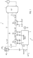
- Fig. 1 shows a block diagram showing the essential components of the present invention.
- the engine 3 of the combined heat and power plant 2 of the food processing plant 1 with generator 18.
- the engine 3 has a supply line 5 for intake air and a supply line 6 for fuel.
- This engine oil 11 can be cooled via the heat exchanger WT1, via the heat transfer medium 10.
- the heat exchanger WT1 is preferably designed as a countercurrent heat exchanger, in particular in the form of a plate heat exchanger, which allows a design with a very low gradient of e.g. 2°C between the coolant inlet temperature (in the example 80°C) and the oil bath return temperature (in the example 82°C) before the cooled oil is returned to the engine 3.
- the volume flow of the circulating engine oil can also influence the average oil bath temperature (in the example 85°C), this is optimized so that the oil bath flow temperature does not exceed 90°C and the average oil bath temperature is 85°C to 88°C.
- the engine 3 also has an engine cooling circuit with cooling medium 12 (usually a water-glycol mixture), which is required to cool the engine block 3.
- This cooling medium 12 can be cooled via the heat exchanger WT2.
- the flow temperature of the cooling medium 12 can be, for example, 85°C to 100°C, here 98°C, with a volume flow of, for example, 38 m 3 /h in a CHP plant with, for example, 450 kW electrical output.
- the cooled engine cooling medium has, for example, a temperature of 85°C to 95°C before it is returned to the engine.
- the "external" heat carrier has, for example, a temperature in the range of 90°C to 100°C after the heat exchanger WT2; in this example, T 3 is 95°C.
- the hot exhaust gases from the engine are led into a corresponding line and are guided to another heat exchanger WT3, here a gas/liquid heat exchanger, in particular a tube bundle heat exchanger.
- the escaping exhaust gas has a temperature of 400°C to 500°C, for example, here 500°C, and after the heat exchanger WT3 a temperature of 100 to 200°C, here 120°C.
- the exhaust gas flows through the third heat exchanger WT3 with a mass flow of about 2200 kg/h.
- the heat transfer medium 10 is thus heated step by step from a temperature T 1 through the heat exchangers WT1, WT2 and WT3 to a temperature of T 4 > 100°C, in particular > 110°C, in this case 110°C.
- the volume flow of the heat transfer medium 10 through all heat exchangers WT1, WT2, WT3 or, if present, a further heat exchanger, is advantageously constant and is, for example, in a range of 10m 3 /h to 20m 3 /h.
- the heated heat carrier 10 can then be supplied via corresponding lines 20 either directly to one or more heat consumers 8 (in Fig. 1 not shown) or advantageously first to an energy storage tank 7 (in an upper corresponding temperature range).
- the energy storage tank 7 is designed in this embodiment as a pressure storage tank so that the heat transfer medium can be stored at high temperatures.
- the energy storage tank 7 is advantageously designed as a stratified storage tank since a heat transfer medium of a certain temperature can then be taken in a known manner or can be generated by a mixing device (not shown).
- the heat transfer medium 10 can then be fed from the heat consumer or consumers 8 either back to the lower area of the energy storage tank 7 or (not shown here) directly to the cogeneration plant for cooling.
- the heat transfer medium 10 is advantageously fed back into the energy storage tank 7.
- the energy storage tank can ensure that any surplus heat flow that is not immediately used can be temporarily stored.
- the cogeneration plant can therefore be operated for a very long time, advantageously always, within the design range. Only when the storage tank 7 reaches a predetermined filling level does the output have to be reduced and the cogeneration plant later switched off completely if necessary.
- the return temperature from the consumers can only be set to a constant value with difficulty. It can therefore be the case that the return temperature T 0 , i.e. the temperature that the returning heat carrier has before it re-enters the first heat exchanger WT1, is too high to cool the components of the cogeneration plant sufficiently. For this reason, the safety heat exchanger WT5 is provided, which makes it possible to set the temperature of the heat carrier 10 to a predetermined value or to a predetermined value range T1 if this is necessary.
- the heated cooling medium 21 can, for example, be brewing water that is stored in a brewing water tank.
- the heat exchanger WT5, for example, is a counterflow plate heat exchanger.
- the heat transfer medium in the energy storage tank 7 in a brewhouse can be used for wort boiling, for example.
- a CHP plant can be designed much larger because it can now also be used directly in the entire brewing process for heating purposes, thus replacing primary energy.
- the first heat exchanger WT1 which cools the oil 11 of the engine, is the first heat exchanger in the series of heat exchangers WT1, WT2, WT3, so that Case it is ensured that a sufficiently low engine oil return temperature (in the example 82°C) is achieved with the heat transfer medium 10.
- the heat transfer medium WT3 is advantageously arranged at the end of the row of at least three heat exchangers, as this also ensures that the cooling medium 12 of the engine's cooling circuit can be sufficiently cooled beforehand so that the engine is not damaged. It can then be ensured that T 2 is in a range of 83°C to 90°C.
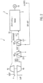
- Fig. 1 illustrates only the basic principle of the present invention. However, it is particularly advantageous for a high mechanical efficiency if the combined heat and power plant has a turbocharger 4 which effectively uses the kinetic energy of the exhaust gas.
- the turbines indicated with 4b are arranged, which drive a compressor 4a via a drive shaft to compress the intake gas.
- the compressed intake gas can have temperatures in a range of 100° to 200° C and must be cooled before it is fed to the engine 3.
- the heat exchanger WT4a can be provided, which cools the compressed intake gas to approximately 95°C to 110°C, here 100°C.
- a cooling medium 22 is fed into the heat exchanger WT4a.
- the pre-cooled intake gas can then be further cooled to 30°C to 50°C using a second heat exchanger WT4b to cool the intake air from the WT4a, before it is fed to the engine 3 together with the fuel.
- the fuel can also be fed before or between the heat exchangers WT4a and WT4b (not shown here).
- cold water with a temperature of 10°C to 25°C, here 12°C, can be used for cooling.
- the cold water can then be heated to a temperature of 30° to 40°C, for example.
- a gas/liquid heat exchanger in particular a finned air/water heat exchanger, is used as the heat exchanger WT4a.
- a gas/liquid heat exchanger is also used as the heat exchanger WT4b.
- Heated cold water from the heat exchanger WT4b can then be fed to the heat exchanger WT5 as a cooling medium (see Fig. 1 ), is further heated in the heat exchanger WT5 and can, as already described, be stored, for example, as hot water in a hot water tank, in particular a brewing water tank.
- the heat exchanger WT4a was also connected in series, namely between the heat exchangers WT2 and WT3.
- the heat carrier 10 then has such high energy that it can be stored, for example, in the top layer of the energy storage tank or can be fed directly to the heat consumer.
- the cold water heated in the heat exchanger WT4b is fed to the heat exchanger WT5 to cool the heat carrier 10 conducted in the circuit K to a target temperature T1.
- a bypass circuit 23, which bridges the heat exchanger WT5, can be activated.
- the bypass 23 can be provided, which guides the cooling medium 21 past the heat exchanger WT5 by closing the valve 24 and opening the valve 25.
- a corresponding bypass line from the line section 25 to the line section 26 can be arranged between the heat exchangers WT1 and WT5, such that the heat exchanger WT5 is bypassed by opening corresponding valves (not shown).
- the coolant 12 of the engine has a lower temperature overall. Consequently, the target temperature for the temperature T 1 can also be somewhat higher > 80°C up to 85°C, for example, but preferably up to 83°C or 85°C, as sufficient cooling of the engine oil and the coolant 12 can then still be achieved.
- This is particularly advantageous as a constant return temperature of 80°C, for example, is difficult to ensure by brewery consumers, and some heat consumers only provide return temperatures of 85°C or 90°C, for example because the medium to be heated must already be heated to 80° to 85°C or tempered to this temperature.
- high return temperatures at the CHP plant (T 0 ) would entail the risk that the CHP plant could be damaged or could not be operated efficiently within the design range because it would have to be turned down.
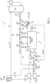
- the cogeneration plant 2 used in this example has a nominal output of 450kW of electrical power at sea level.
- Heat exchangers WT1 and WT2 can be used for this purpose in an advantageous and clever manner.
- the heat carrier 10 is preferably fed from the lower and/or upper region (not shown) of the energy storage tank 7 at a temperature T 1 of 60°C to 90°C to the heat exchanger WT1, the heat exchanger WT5 being bypassed here, for example, by bypass 23.
- the engine oil can now be slowly heated via the heat exchanger WT1 from an initial temperature in the range of, for example, 30°C to 40°C to an operating temperature in a range of, for example, 80°C to 90°C.
- the oil circuit in the engine 3 must of course be in operation for this to happen.
- the heat carrier 10 can then also be fed to the heat exchanger WT2.
- the heat exchanger WT2 can then be used to increase the cooling medium 12, which cools the engine block, from an initial temperature in the range of 30°C to 40°C to 80°C to 90°C, for example.
- the internal cooling circuit of the engine 3 is in operation.
- the heat transfer medium 10 can then be passed on through the heat exchangers WT4a and WT3, whereby heat energy can be transferred to the heat transfer medium 10 in the initial phase, i.e. shortly after starting.
- the heat transfer medium 10 can then be returned to the energy storage tank 7, but advantageously not to the upper area, but rather, although not shown here, to a middle or lower area in which the colder medium is stored.
- the clever use of the heat exchangers WT1 and WT2 for preheating reduces the fuel requirement for the warm-up phase and also significantly reduces engine wear.
- the cogeneration plant can be operated more quickly under load. It is therefore generally advantageous that the heat transfer medium 10 heated by the cogeneration plant and stored in the energy storage tank 7 can be reused the next time the cogeneration plant 2 is restarted.
- intake gas here ambient air
- intake gas is compressed as intake gas by a compressor 4a of the turbocharger.
- the temperature increases, for example, to 100° to 200°C, in this example e.g. 180°C.
- the heat exchanger WT4a cools the compressed hot intake gas to a lower temperature in a range of e.g. 90°C to 110°C, here 100°C, with the help of the circulating heat transfer medium 10.
- the volume flow of the intake gas in the example is approximately 2200kg/h.
- the pre-cooled compressed intake gas is then further cooled to a temperature of 30°C to 50°C via a second heat exchanger WT4b and after fuel has been added to the intake gas in a predetermined mixing ratio, the mixture can be fed to the engine in a known manner.
- the heat exchanger WT1 is used to cool the engine 3. It cools the engine oil, for example, from an oil bath flow temperature of 80°C to 90°C, here for example from 88° to 82°C.
- the heat exchanger WT1 here has an inlet temperature of 80°C.
- the temperature T 1 could also be increased to up to 83°C or even up to 85°C, since the heat exchanger WT4a is connected in series with the heat exchangers WT1, WT3 and heats up the heat transfer medium 10 and the energy of the compressed intake gas is not released into the engine's cooling circuit.
- the cooling medium 12 is cooled, for example, from temperatures in a range of 85°C to 100°C to temperatures in a range of 85°C to 95°C.
- the volume flow of the cooling medium 12 is, for example, in a range of 30m 3 /h to 40m 3 /h in a CHP plant.
- the heat transfer medium 10 is heated by the heat exchanger WT2 to a temperature range T 3 of 85°C to 95°C, here 91°C, and then enters the gas/liquid heat exchanger WT4a and is heated to a temperature T 4a in a range of 95°C to 98°C, in particular here 95°C.
- the exhaust gas leaves the engine at a temperature of, for example, 400°C to 500°C, enters the turbocharger 4b and drives its turbine blades, which in turn are coupled to the compressor 4a.
- the volume flow of the exhaust gas in the example is just over 2200kg/h
- the hot heat transfer medium 10 is now available to the brewery or the food processing plant as a heating medium.
- the heat transfer medium 10 can be stored in the top layer of the energy storage tank 7 or can also be fed directly to the consumer, for example a bottle washing machine (not shown). If the heat transfer medium 10 is stored in the energy storage tank 7, it can be passed on from there to the heat consumer(s) 8.
- the heat transfer medium is then taken from the top area of the energy storage tank. If there are heat consumers that require lower temperatures, heat transfer medium of a certain temperature can be taken from several extraction points or the heat transfer medium can be mixed to a certain temperature (with the aim of getting the lowest possible return temperature from the consumer).
- the heat transfer medium which has cooled down in the meantime, can be stored again in the lower area of the heat storage tank 7. It would also be possible for the cooled heat transfer medium is fed directly back to the heat exchanger WT5 of the cogeneration plant (not shown).
- a temperature sensor (not shown), which can be used to detect the return temperature at which the heat transfer medium 10 is returned to the cogeneration plant, can be used to determine whether the temperature T 0 corresponds to a certain target temperature T 1 or is within a certain range. If the temperature T 0 is too high, the heat transfer medium 10 can be cooled to a suitable temperature T 1 via the heat exchanger WT5, here for example from a temperature in a range of 82° to 85°C to a temperature T1 of 80°C.
- the heat exchanger WT5 can be bypassed or a bypass circuit for the cooling medium 21 can be activated, for example by closing the valve 24 and opening the valve 25 of the bypass 23.
- the heat transfer medium 10 then flows uncooled through the heat exchanger WT5.
- the heat transfer medium 10 could also be routed past the heat exchanger WT5 via a corresponding bypass circuit (not shown).
- the heat transfer medium 10 then re-enters the heat exchanger WT1 as described above and circulates in the circuit K.
- the volume flow of the heat transfer medium 10 in this process is, for example, in a range of 10m 3 /h to 20m 3 /h.
- the volume flow of the heat transfer medium 10 through the heat exchangers WT1, WT2, WT3, WT4a can be constant.
- cold water at 10°C to 25°C, in the example 12°C can be heated to a temperature of 30° to 40°C using the heat exchanger WT4b.
- the heated medium from the heat exchanger WT4b can then be fed to the heat exchanger WT5 as a cooling medium 21 and heated to, for example, 40° to 80°C or 35° - 85 °C.
- valves particularly between the heat exchangers, or temperature sensors for recording the respective temperatures of the media entering and leaving the heat exchangers have not been explained or described in detail in the schematic representations.
- the system can also have a control and regulating device that controls the individual valves and, based on the measured temperatures, controls corresponding control valves or shut-off valves (bypass) so that the corresponding temperatures reach their target values.
- At least one of the heat exchangers connected in series can be bridged via a bypass line, so that it is possible, if required, to bypass at least part of the heat transfer medium in the bypass past the corresponding heat exchanger using appropriate control valve(s).
- the heat carrier 10 can be, for example, water.
- a mixing device (not shown) can also be provided between the energy storage tank 7 and the heat exchanger WT5 for setting a temperature T 0 of the heat transfer medium.
- the invention also relates to a cogeneration plant suitable for food processing plants with thermal energy for heating a heat carrier with thermal energy, wherein the heat carrier is heated by waste heat from the cogeneration plant via at least three heat exchangers WT1, WT2, WT3 connected in series, wherein the cogeneration plant can be constructed as explained in the claims or the description.
- the heat exchanger WT4a can also be arranged in series with WT1, WT2, WT3, in front of WT1, in particular between WT5 and WT1 or alternatively between WT1 and WT2. Heat exchanger WT4a can then nevertheless be coupled to WT4b as described in the previous embodiments (which can then also be coupled to WT5 as described above).
- the heat exchangers WT1, 2, 3, 4a, 4b, 5 are preferably designed or connected as countercurrent heat exchangers.
Landscapes
- Engineering & Computer Science (AREA)
- Chemical & Material Sciences (AREA)
- Organic Chemistry (AREA)
- General Engineering & Computer Science (AREA)
- Bioinformatics & Cheminformatics (AREA)
- Food Science & Technology (AREA)
- Health & Medical Sciences (AREA)
- Life Sciences & Earth Sciences (AREA)
- Biochemistry (AREA)
- Mechanical Engineering (AREA)
- General Health & Medical Sciences (AREA)
- Genetics & Genomics (AREA)
- Combustion & Propulsion (AREA)
- Wood Science & Technology (AREA)
- Zoology (AREA)
- Heat-Pump Type And Storage Water Heaters (AREA)
- Heat-Exchange Devices With Radiators And Conduit Assemblies (AREA)
Applications Claiming Priority (2)
| Application Number | Priority Date | Filing Date | Title |
|---|---|---|---|
| DE102014220334.1A DE102014220334A1 (de) | 2014-10-07 | 2014-10-07 | Lebensmitteltechnische Prozessanlage, insbesondere Brauereianlage mit Blockheizkraft |
| PCT/EP2015/073194 WO2016055548A1 (de) | 2014-10-07 | 2015-10-07 | Lebensmitteltechnische prozessanlage, insbesondere brauereianlage mit blockheizkraft |
Publications (3)
| Publication Number | Publication Date |
|---|---|
| EP3204482A1 EP3204482A1 (de) | 2017-08-16 |
| EP3204482B1 EP3204482B1 (de) | 2021-01-13 |
| EP3204482B2 true EP3204482B2 (de) | 2024-11-13 |
Family
ID=54347484
Family Applications (1)
| Application Number | Title | Priority Date | Filing Date |
|---|---|---|---|
| EP15784586.8A Active EP3204482B2 (de) | 2014-10-07 | 2015-10-07 | Lebensmitteltechnische prozessanlage, insbesondere brauereianlage mit blockheizkraft |
Country Status (5)
| Country | Link |
|---|---|
| EP (1) | EP3204482B2 (da) |
| CN (1) | CN106795466A (da) |
| DE (1) | DE102014220334A1 (da) |
| DK (1) | DK3204482T4 (da) |
| WO (1) | WO2016055548A1 (da) |
Families Citing this family (1)
| Publication number | Priority date | Publication date | Assignee | Title |
|---|---|---|---|---|
| DE102023101426A1 (de) * | 2023-01-20 | 2024-07-25 | Gea Brewery Systems Gmbh | Verfahren und Vorrichtung zur Energierückgewinnung und/oder Energieeinsparung beim Brauen und/oder beim Brennen einer Brauflüssigkeit |
Family Cites Families (16)
| Publication number | Priority date | Publication date | Assignee | Title |
|---|---|---|---|---|
| DE3147620C1 (de) * | 1981-12-02 | 1991-06-20 | Bernhard Dipl.-Braum. 8710 Kitzingen Lenz | Energiesparendes Verfahren zum diskontinuierlichen Bierwuerzekochen |
| DE3711251A1 (de) * | 1987-04-03 | 1988-10-13 | Steinecker Maschf Anton | Brauereianlage |
| EP1053438B1 (de) | 1998-02-03 | 2002-07-24 | Miturbo Umwelttechnik GmbH & Co. KG | Verfahren und vorrichtung für wärmetransformation zur erzeugung von heizmedien |
| DE10339564A1 (de) | 2002-08-28 | 2004-03-11 | RÄSS, Martin | Blockheizkraftwerk und Verfahren zum Betrieb desselben |
| US20090211253A1 (en) * | 2005-06-16 | 2009-08-27 | Utc Power Corporation | Organic Rankine Cycle Mechanically and Thermally Coupled to an Engine Driving a Common Load |
| DE102007054429A1 (de) * | 2007-11-13 | 2009-05-14 | Krones Ag | Brauverfahren und Brauereianlagen |
| DE202008014330U1 (de) * | 2008-10-28 | 2009-01-22 | Kaspar Schulz Brauereimaschinenfabrik & Apparatebauanstalt Kg | Vorrichtung zur Energieversorgung einer Brauerei |
| DE202009002103U1 (de) | 2009-02-13 | 2009-05-28 | ENERATIO Ingenieurbüro für rationellen Energieeinsatz GbR (vertretungsberechtiger Gesellschafter: Herrn Michael Müller, 21220 Seevetal) | Vorrichtung zur Wärmerückgewinnung in einem BHKW |
| DE102009011475B4 (de) * | 2009-03-06 | 2012-05-16 | Lichtblick Zuhausekraftwerk Gmbh | Modulares Blockheizkraftwerk |
| DE102009013570A1 (de) | 2009-03-17 | 2010-09-30 | Siemens Aktiengesellschaft | Kraftwerksanlage mit zwei Kreisläufen sowie ein Verfahren zum Betrieb einer Kraftwerksanlage |
| DE102009013579A1 (de) * | 2009-03-19 | 2010-09-23 | Gea Brewery Systems Gmbh | Brauereianlage zur Herstellung und Abfüllung von Bier |
| DE102009036019A1 (de) * | 2009-08-04 | 2011-02-10 | Krones Ag | Verfahren und Vorrichtung zur Erhitzung, insbesondere von hochviskosen Produkten |
| DE102009044258A1 (de) * | 2009-10-15 | 2011-05-05 | Krones Ag | Anlage und Verfahren zur Herstellung, Abfüllung, Verpackung und/oder Transport von Getränken |
| SE535877C2 (sv) * | 2010-05-25 | 2013-01-29 | Scania Cv Ab | Kylarrangemang hos ett fordon som drivs av en överladdad förbränningsmotor |
| DE102010060919A1 (de) * | 2010-12-01 | 2012-06-06 | Schmidmeier Naturenergie Gmbh | Vorrichtung und Verfahren zur dampflosen Pasteurisierung von abgefüllten Lebensmitteln |
| DE102012219964A1 (de) | 2012-10-31 | 2014-04-30 | Krones Ag | Gekühltes Warmwasser |
-
2014
- 2014-10-07 DE DE102014220334.1A patent/DE102014220334A1/de active Pending
-
2015
- 2015-10-07 WO PCT/EP2015/073194 patent/WO2016055548A1/de not_active Ceased
- 2015-10-07 DK DK15784586.8T patent/DK3204482T4/da active
- 2015-10-07 EP EP15784586.8A patent/EP3204482B2/de active Active
- 2015-10-07 CN CN201580054303.4A patent/CN106795466A/zh active Pending
Also Published As
| Publication number | Publication date |
|---|---|
| CN106795466A (zh) | 2017-05-31 |
| WO2016055548A1 (de) | 2016-04-14 |
| DK3204482T4 (da) | 2025-02-10 |
| DE102014220334A1 (de) | 2016-04-07 |
| EP3204482B1 (de) | 2021-01-13 |
| DK3204482T3 (da) | 2021-04-19 |
| EP3204482A1 (de) | 2017-08-16 |
Similar Documents
| Publication | Publication Date | Title |
|---|---|---|
| DE102010060319B4 (de) | Kühlsystem | |
| DE102009059316B4 (de) | Vorrichtung zum Starten einer Dampfturbine gegen Nenndruck | |
| DE102008035955B4 (de) | Kühlstrategie | |
| DE102009025932A1 (de) | System zur Rückgewinnung der durch ein Zusatzsystem einer Turbomaschine erzeugten Abwärme | |
| DE4213023A1 (de) | Verfahren zum Betrieb eines Gasturbogruppe | |
| EP2630230B1 (de) | Verfahren und vorrichtung zum steuern der warmwassererzeugung beim brauen von bier in einer bierbrauerei | |
| DE102010011556A1 (de) | Vorrichtung zur Brennstoffversorgung | |
| DE102014019684A1 (de) | Anordnung zur Umwandlung thermischer Energie aus Verlustwärme einer Verbrennungskraftmaschine | |
| CH705929A1 (de) | Verfahren zum Betreiben eines Kombikraftwerkes. | |
| DE112011102951B4 (de) | Abgasturbolader eines Verbrennungsmotors | |
| DE102011055147B4 (de) | Verfahren zur Einspeisung von Wärmeenergie in ein in einer lebensmitteltechnischen Prozessanlage zu verarbeitendes Prozessmittel sowie Wärmeversorgungssystem dafür | |
| DE102011101337A1 (de) | Kreislaufanordnung zur Kühlung einer Brennkraftmaschine und Verfahren zum Betrieb einer derartigen Kreislaufanordnung | |
| DE102009000657A1 (de) | Brennkraftmaschine mit Trockensumpfschmierung und Verfahren zum Betreiben einer derartigen Brennkraftmaschine | |
| EP1154127B1 (de) | Verfahren zum Betrieb eines Kombikraftwerkes sowie Kombikraftwerk zur Durchführung des Verfahrens | |
| DE69711608T2 (de) | Methode und einrichtung zur rückgewinnung von wärme aus der ladeluft eines motors | |
| EP3204482B2 (de) | Lebensmitteltechnische prozessanlage, insbesondere brauereianlage mit blockheizkraft | |
| DE102015106336A1 (de) | Wärmekreislauf für eine Antriebsvorrichtung eines Fahrzeugs | |
| DE102006034194A1 (de) | Kombiniertes Kühl- und Heizsystem | |
| DE102012113207A1 (de) | System und Verfahren zur Kühlung eines Verbrennungsmotors eines Fahrzeugs | |
| DE102010036581A1 (de) | Flüssigkeitsgekühlte Brennkraftmaschine mit kühlmittelbetriebener Heizung und Verfahren zum Betreiben einer derartigen Brennkraftmaschine | |
| EP4379875A1 (de) | Vorrichtung und verfahren zur temperierung eines wasserstoffbetriebenen fahrzeuges | |
| WO2013013788A1 (de) | Verfahren zur nutzung von wärmeenergien, vorzugsweise bei einer stranggiessanlage | |
| DE102010060919A1 (de) | Vorrichtung und Verfahren zur dampflosen Pasteurisierung von abgefüllten Lebensmitteln | |
| WO2012152602A1 (de) | Leitungskreis und verfahren zum betreiben eines leitungskreises zur abwärmenutzung einer brennkraftmaschine | |
| EP2423577A2 (de) | Verfahren zur Rückgewinnung von Energie aus dem Abgas eines Brenners |
Legal Events
| Date | Code | Title | Description |
|---|---|---|---|
| STAA | Information on the status of an ep patent application or granted ep patent |
Free format text: STATUS: THE INTERNATIONAL PUBLICATION HAS BEEN MADE |
|
| PUAI | Public reference made under article 153(3) epc to a published international application that has entered the european phase |
Free format text: ORIGINAL CODE: 0009012 |
|
| STAA | Information on the status of an ep patent application or granted ep patent |
Free format text: STATUS: REQUEST FOR EXAMINATION WAS MADE |
|
| 17P | Request for examination filed |
Effective date: 20170302 |
|
| AK | Designated contracting states |
Kind code of ref document: A1 Designated state(s): AL AT BE BG CH CY CZ DE DK EE ES FI FR GB GR HR HU IE IS IT LI LT LU LV MC MK MT NL NO PL PT RO RS SE SI SK SM TR |
|
| AX | Request for extension of the european patent |
Extension state: BA ME |
|
| DAV | Request for validation of the european patent (deleted) | ||
| DAX | Request for extension of the european patent (deleted) | ||
| STAA | Information on the status of an ep patent application or granted ep patent |
Free format text: STATUS: EXAMINATION IS IN PROGRESS |
|
| 17Q | First examination report despatched |
Effective date: 20181005 |
|
| GRAP | Despatch of communication of intention to grant a patent |
Free format text: ORIGINAL CODE: EPIDOSNIGR1 |
|
| STAA | Information on the status of an ep patent application or granted ep patent |
Free format text: STATUS: GRANT OF PATENT IS INTENDED |
|
| INTG | Intention to grant announced |
Effective date: 20200724 |
|
| GRAS | Grant fee paid |
Free format text: ORIGINAL CODE: EPIDOSNIGR3 |
|
| GRAA | (expected) grant |
Free format text: ORIGINAL CODE: 0009210 |
|
| STAA | Information on the status of an ep patent application or granted ep patent |
Free format text: STATUS: THE PATENT HAS BEEN GRANTED |
|
| AK | Designated contracting states |
Kind code of ref document: B1 Designated state(s): AL AT BE BG CH CY CZ DE DK EE ES FI FR GB GR HR HU IE IS IT LI LT LU LV MC MK MT NL NO PL PT RO RS SE SI SK SM TR |
|
| REG | Reference to a national code |
Ref country code: GB Ref legal event code: FG4D Free format text: NOT ENGLISH |
|
| REG | Reference to a national code |
Ref country code: CH Ref legal event code: EP |
|
| REG | Reference to a national code |
Ref country code: IE Ref legal event code: FG4D Free format text: LANGUAGE OF EP DOCUMENT: GERMAN |
|
| REG | Reference to a national code |
Ref country code: DE Ref legal event code: R096 Ref document number: 502015014154 Country of ref document: DE |
|
| REG | Reference to a national code |
Ref country code: AT Ref legal event code: REF Ref document number: 1354581 Country of ref document: AT Kind code of ref document: T Effective date: 20210215 |
|
| REG | Reference to a national code |
Ref country code: NL Ref legal event code: FP |
|
| REG | Reference to a national code |
Ref country code: DK Ref legal event code: T3 Effective date: 20210412 |
|
| REG | Reference to a national code |
Ref country code: LT Ref legal event code: MG9D |
|
| PG25 | Lapsed in a contracting state [announced via postgrant information from national office to epo] |
Ref country code: NO Free format text: LAPSE BECAUSE OF FAILURE TO SUBMIT A TRANSLATION OF THE DESCRIPTION OR TO PAY THE FEE WITHIN THE PRESCRIBED TIME-LIMIT Effective date: 20210413 Ref country code: BG Free format text: LAPSE BECAUSE OF FAILURE TO SUBMIT A TRANSLATION OF THE DESCRIPTION OR TO PAY THE FEE WITHIN THE PRESCRIBED TIME-LIMIT Effective date: 20210413 Ref country code: HR Free format text: LAPSE BECAUSE OF FAILURE TO SUBMIT A TRANSLATION OF THE DESCRIPTION OR TO PAY THE FEE WITHIN THE PRESCRIBED TIME-LIMIT Effective date: 20210113 Ref country code: FI Free format text: LAPSE BECAUSE OF FAILURE TO SUBMIT A TRANSLATION OF THE DESCRIPTION OR TO PAY THE FEE WITHIN THE PRESCRIBED TIME-LIMIT Effective date: 20210113 Ref country code: GR Free format text: LAPSE BECAUSE OF FAILURE TO SUBMIT A TRANSLATION OF THE DESCRIPTION OR TO PAY THE FEE WITHIN THE PRESCRIBED TIME-LIMIT Effective date: 20210414 Ref country code: PT Free format text: LAPSE BECAUSE OF FAILURE TO SUBMIT A TRANSLATION OF THE DESCRIPTION OR TO PAY THE FEE WITHIN THE PRESCRIBED TIME-LIMIT Effective date: 20210513 Ref country code: LT Free format text: LAPSE BECAUSE OF FAILURE TO SUBMIT A TRANSLATION OF THE DESCRIPTION OR TO PAY THE FEE WITHIN THE PRESCRIBED TIME-LIMIT Effective date: 20210113 |
|
| PG25 | Lapsed in a contracting state [announced via postgrant information from national office to epo] |
Ref country code: SE Free format text: LAPSE BECAUSE OF FAILURE TO SUBMIT A TRANSLATION OF THE DESCRIPTION OR TO PAY THE FEE WITHIN THE PRESCRIBED TIME-LIMIT Effective date: 20210113 Ref country code: PL Free format text: LAPSE BECAUSE OF FAILURE TO SUBMIT A TRANSLATION OF THE DESCRIPTION OR TO PAY THE FEE WITHIN THE PRESCRIBED TIME-LIMIT Effective date: 20210113 Ref country code: LV Free format text: LAPSE BECAUSE OF FAILURE TO SUBMIT A TRANSLATION OF THE DESCRIPTION OR TO PAY THE FEE WITHIN THE PRESCRIBED TIME-LIMIT Effective date: 20210113 Ref country code: RS Free format text: LAPSE BECAUSE OF FAILURE TO SUBMIT A TRANSLATION OF THE DESCRIPTION OR TO PAY THE FEE WITHIN THE PRESCRIBED TIME-LIMIT Effective date: 20210113 |
|
| PG25 | Lapsed in a contracting state [announced via postgrant information from national office to epo] |
Ref country code: IS Free format text: LAPSE BECAUSE OF FAILURE TO SUBMIT A TRANSLATION OF THE DESCRIPTION OR TO PAY THE FEE WITHIN THE PRESCRIBED TIME-LIMIT Effective date: 20210513 |
|
| REG | Reference to a national code |
Ref country code: DE Ref legal event code: R026 Ref document number: 502015014154 Country of ref document: DE |
|
| PLBI | Opposition filed |
Free format text: ORIGINAL CODE: 0009260 |
|
| PLAX | Notice of opposition and request to file observation + time limit sent |
Free format text: ORIGINAL CODE: EPIDOSNOBS2 |
|
| PG25 | Lapsed in a contracting state [announced via postgrant information from national office to epo] |
Ref country code: EE Free format text: LAPSE BECAUSE OF FAILURE TO SUBMIT A TRANSLATION OF THE DESCRIPTION OR TO PAY THE FEE WITHIN THE PRESCRIBED TIME-LIMIT Effective date: 20210113 Ref country code: CZ Free format text: LAPSE BECAUSE OF FAILURE TO SUBMIT A TRANSLATION OF THE DESCRIPTION OR TO PAY THE FEE WITHIN THE PRESCRIBED TIME-LIMIT Effective date: 20210113 Ref country code: SM Free format text: LAPSE BECAUSE OF FAILURE TO SUBMIT A TRANSLATION OF THE DESCRIPTION OR TO PAY THE FEE WITHIN THE PRESCRIBED TIME-LIMIT Effective date: 20210113 |
|
| 26 | Opposition filed |
Opponent name: KHS GMBH Effective date: 20211013 |
|
| PG25 | Lapsed in a contracting state [announced via postgrant information from national office to epo] |
Ref country code: SK Free format text: LAPSE BECAUSE OF FAILURE TO SUBMIT A TRANSLATION OF THE DESCRIPTION OR TO PAY THE FEE WITHIN THE PRESCRIBED TIME-LIMIT Effective date: 20210113 Ref country code: RO Free format text: LAPSE BECAUSE OF FAILURE TO SUBMIT A TRANSLATION OF THE DESCRIPTION OR TO PAY THE FEE WITHIN THE PRESCRIBED TIME-LIMIT Effective date: 20210113 |
|
| PG25 | Lapsed in a contracting state [announced via postgrant information from national office to epo] |
Ref country code: AL Free format text: LAPSE BECAUSE OF FAILURE TO SUBMIT A TRANSLATION OF THE DESCRIPTION OR TO PAY THE FEE WITHIN THE PRESCRIBED TIME-LIMIT Effective date: 20210113 Ref country code: ES Free format text: LAPSE BECAUSE OF FAILURE TO SUBMIT A TRANSLATION OF THE DESCRIPTION OR TO PAY THE FEE WITHIN THE PRESCRIBED TIME-LIMIT Effective date: 20210113 |
|
| PG25 | Lapsed in a contracting state [announced via postgrant information from national office to epo] |
Ref country code: SI Free format text: LAPSE BECAUSE OF FAILURE TO SUBMIT A TRANSLATION OF THE DESCRIPTION OR TO PAY THE FEE WITHIN THE PRESCRIBED TIME-LIMIT Effective date: 20210113 |
|
| PLBB | Reply of patent proprietor to notice(s) of opposition received |
Free format text: ORIGINAL CODE: EPIDOSNOBS3 |
|
| REG | Reference to a national code |
Ref country code: CH Ref legal event code: PL |
|
| PG25 | Lapsed in a contracting state [announced via postgrant information from national office to epo] |
Ref country code: IS Free format text: LAPSE BECAUSE OF FAILURE TO SUBMIT A TRANSLATION OF THE DESCRIPTION OR TO PAY THE FEE WITHIN THE PRESCRIBED TIME-LIMIT Effective date: 20210513 |
|
| GBPC | Gb: european patent ceased through non-payment of renewal fee |
Effective date: 20211007 |
|
| PG25 | Lapsed in a contracting state [announced via postgrant information from national office to epo] |
Ref country code: MC Free format text: LAPSE BECAUSE OF FAILURE TO SUBMIT A TRANSLATION OF THE DESCRIPTION OR TO PAY THE FEE WITHIN THE PRESCRIBED TIME-LIMIT Effective date: 20210113 |
|
| PG25 | Lapsed in a contracting state [announced via postgrant information from national office to epo] |
Ref country code: LU Free format text: LAPSE BECAUSE OF NON-PAYMENT OF DUE FEES Effective date: 20211007 Ref country code: GB Free format text: LAPSE BECAUSE OF NON-PAYMENT OF DUE FEES Effective date: 20211007 |
|
| PG25 | Lapsed in a contracting state [announced via postgrant information from national office to epo] |
Ref country code: LI Free format text: LAPSE BECAUSE OF NON-PAYMENT OF DUE FEES Effective date: 20211031 Ref country code: CH Free format text: LAPSE BECAUSE OF NON-PAYMENT OF DUE FEES Effective date: 20211031 |
|
| PG25 | Lapsed in a contracting state [announced via postgrant information from national office to epo] |
Ref country code: FR Free format text: LAPSE BECAUSE OF NON-PAYMENT OF DUE FEES Effective date: 20211031 |
|
| PG25 | Lapsed in a contracting state [announced via postgrant information from national office to epo] |
Ref country code: IE Free format text: LAPSE BECAUSE OF NON-PAYMENT OF DUE FEES Effective date: 20211007 |
|
| PG25 | Lapsed in a contracting state [announced via postgrant information from national office to epo] |
Ref country code: HU Free format text: LAPSE BECAUSE OF FAILURE TO SUBMIT A TRANSLATION OF THE DESCRIPTION OR TO PAY THE FEE WITHIN THE PRESCRIBED TIME-LIMIT; INVALID AB INITIO Effective date: 20151007 |
|
| P01 | Opt-out of the competence of the unified patent court (upc) registered |
Effective date: 20230523 |
|
| PG25 | Lapsed in a contracting state [announced via postgrant information from national office to epo] |
Ref country code: CY Free format text: LAPSE BECAUSE OF FAILURE TO SUBMIT A TRANSLATION OF THE DESCRIPTION OR TO PAY THE FEE WITHIN THE PRESCRIBED TIME-LIMIT Effective date: 20210113 |
|
| PG25 | Lapsed in a contracting state [announced via postgrant information from national office to epo] |
Ref country code: MK Free format text: LAPSE BECAUSE OF FAILURE TO SUBMIT A TRANSLATION OF THE DESCRIPTION OR TO PAY THE FEE WITHIN THE PRESCRIBED TIME-LIMIT Effective date: 20210113 |
|
| APBP | Date of receipt of notice of appeal recorded |
Free format text: ORIGINAL CODE: EPIDOSNNOA2O |
|
| APAW | Appeal reference deleted |
Free format text: ORIGINAL CODE: EPIDOSDREFNO |
|
| APAH | Appeal reference modified |
Free format text: ORIGINAL CODE: EPIDOSCREFNO |
|
| APBU | Appeal procedure closed |
Free format text: ORIGINAL CODE: EPIDOSNNOA9O |
|
| PG25 | Lapsed in a contracting state [announced via postgrant information from national office to epo] |
Ref country code: MT Free format text: LAPSE BECAUSE OF FAILURE TO SUBMIT A TRANSLATION OF THE DESCRIPTION OR TO PAY THE FEE WITHIN THE PRESCRIBED TIME-LIMIT Effective date: 20210113 |
|
| PUAH | Patent maintained in amended form |
Free format text: ORIGINAL CODE: 0009272 |
|
| STAA | Information on the status of an ep patent application or granted ep patent |
Free format text: STATUS: PATENT MAINTAINED AS AMENDED |
|
| 27A | Patent maintained in amended form |
Effective date: 20241113 |
|
| AK | Designated contracting states |
Kind code of ref document: B2 Designated state(s): AL AT BE BG CH CY CZ DE DK EE ES FI FR GB GR HR HU IE IS IT LI LT LU LV MC MK MT NL NO PL PT RO RS SE SI SK SM TR |
|
| REG | Reference to a national code |
Ref country code: DE Ref legal event code: R102 Ref document number: 502015014154 Country of ref document: DE |
|
| REG | Reference to a national code |
Ref country code: NL Ref legal event code: FP |
|
| REG | Reference to a national code |
Ref country code: DK Ref legal event code: T4 Effective date: 20250204 |
|
| PGFP | Annual fee paid to national office [announced via postgrant information from national office to epo] |
Ref country code: NL Payment date: 20250912 Year of fee payment: 11 Ref country code: IT Payment date: 20250922 Year of fee payment: 11 |
|
| PGFP | Annual fee paid to national office [announced via postgrant information from national office to epo] |
Ref country code: BE Payment date: 20250917 Year of fee payment: 11 |
|
| PG25 | Lapsed in a contracting state [announced via postgrant information from national office to epo] |
Ref country code: TR Free format text: LAPSE BECAUSE OF FAILURE TO SUBMIT A TRANSLATION OF THE DESCRIPTION OR TO PAY THE FEE WITHIN THE PRESCRIBED TIME-LIMIT Effective date: 20210113 |
|
| PGFP | Annual fee paid to national office [announced via postgrant information from national office to epo] |
Ref country code: DE Payment date: 20250902 Year of fee payment: 11 |
|
| PGFP | Annual fee paid to national office [announced via postgrant information from national office to epo] |
Ref country code: AT Payment date: 20250925 Year of fee payment: 11 |
|
| PGFP | Annual fee paid to national office [announced via postgrant information from national office to epo] |
Ref country code: DK Payment date: 20251014 Year of fee payment: 11 |