EP3204596B1 - Chauffage de gisement - Google Patents
Chauffage de gisement Download PDFInfo
- Publication number
- EP3204596B1 EP3204596B1 EP15794866.2A EP15794866A EP3204596B1 EP 3204596 B1 EP3204596 B1 EP 3204596B1 EP 15794866 A EP15794866 A EP 15794866A EP 3204596 B1 EP3204596 B1 EP 3204596B1
- Authority
- EP
- European Patent Office
- Prior art keywords
- alternating current
- conductor loop
- generator
- conductor
- deposit
- Prior art date
- Legal status (The legal status is an assumption and is not a legal conclusion. Google has not performed a legal analysis and makes no representation as to the accuracy of the status listed.)
- Not-in-force
Links
- 238000010438 heat treatment Methods 0.000 title claims description 26
- 239000004020 conductor Substances 0.000 claims description 103
- 229930195733 hydrocarbon Natural products 0.000 claims description 12
- 150000002430 hydrocarbons Chemical class 0.000 claims description 12
- 238000000034 method Methods 0.000 claims description 10
- 239000000126 substance Substances 0.000 claims description 8
- 239000004215 Carbon black (E152) Substances 0.000 claims description 4
- 239000002689 soil Substances 0.000 description 25
- 239000000295 fuel oil Substances 0.000 description 9
- 239000003990 capacitor Substances 0.000 description 7
- 238000009413 insulation Methods 0.000 description 7
- 230000001965 increasing effect Effects 0.000 description 5
- 239000004058 oil shale Substances 0.000 description 5
- 239000010426 asphalt Substances 0.000 description 4
- 238000006243 chemical reaction Methods 0.000 description 4
- 238000010292 electrical insulation Methods 0.000 description 4
- 230000001939 inductive effect Effects 0.000 description 4
- 239000003921 oil Substances 0.000 description 4
- 238000002955 isolation Methods 0.000 description 3
- 238000011065 in-situ storage Methods 0.000 description 2
- 238000004519 manufacturing process Methods 0.000 description 2
- 230000002411 adverse Effects 0.000 description 1
- 230000008033 biological extinction Effects 0.000 description 1
- 230000015572 biosynthetic process Effects 0.000 description 1
- 230000001419 dependent effect Effects 0.000 description 1
- 238000011161 development Methods 0.000 description 1
- 230000018109 developmental process Effects 0.000 description 1
- 238000010586 diagram Methods 0.000 description 1
- 238000012423 maintenance Methods 0.000 description 1
- 239000003027 oil sand Substances 0.000 description 1
- 239000002918 waste heat Substances 0.000 description 1
Images
Classifications
-
- E—FIXED CONSTRUCTIONS
- E21—EARTH OR ROCK DRILLING; MINING
- E21B—EARTH OR ROCK DRILLING; OBTAINING OIL, GAS, WATER, SOLUBLE OR MELTABLE MATERIALS OR A SLURRY OF MINERALS FROM WELLS
- E21B36/00—Heating, cooling or insulating arrangements for boreholes or wells, e.g. for use in permafrost zones
- E21B36/04—Heating, cooling or insulating arrangements for boreholes or wells, e.g. for use in permafrost zones using electrical heaters
-
- E—FIXED CONSTRUCTIONS
- E21—EARTH OR ROCK DRILLING; MINING
- E21B—EARTH OR ROCK DRILLING; OBTAINING OIL, GAS, WATER, SOLUBLE OR MELTABLE MATERIALS OR A SLURRY OF MINERALS FROM WELLS
- E21B43/00—Methods or apparatus for obtaining oil, gas, water, soluble or meltable materials or a slurry of minerals from wells
- E21B43/16—Enhanced recovery methods for obtaining hydrocarbons
- E21B43/24—Enhanced recovery methods for obtaining hydrocarbons using heat, e.g. steam injection
- E21B43/2401—Enhanced recovery methods for obtaining hydrocarbons using heat, e.g. steam injection by means of electricity
-
- H—ELECTRICITY
- H05—ELECTRIC TECHNIQUES NOT OTHERWISE PROVIDED FOR
- H05B—ELECTRIC HEATING; ELECTRIC LIGHT SOURCES NOT OTHERWISE PROVIDED FOR; CIRCUIT ARRANGEMENTS FOR ELECTRIC LIGHT SOURCES, IN GENERAL
- H05B6/00—Heating by electric, magnetic or electromagnetic fields
- H05B6/02—Induction heating
- H05B6/10—Induction heating apparatus, other than furnaces, for specific applications
-
- H—ELECTRICITY
- H05—ELECTRIC TECHNIQUES NOT OTHERWISE PROVIDED FOR
- H05B—ELECTRIC HEATING; ELECTRIC LIGHT SOURCES NOT OTHERWISE PROVIDED FOR; CIRCUIT ARRANGEMENTS FOR ELECTRIC LIGHT SOURCES, IN GENERAL
- H05B2214/00—Aspects relating to resistive heating, induction heating and heating using microwaves, covered by groups H05B3/00, H05B6/00
- H05B2214/03—Heating of hydrocarbons
Definitions
- the invention relates to a deposit heating for inductive heating of a soil, in particular an oil sands, oil shale, heavy oil or heavy oil deposit.
- hydrocarbons from an underground deposit for example, for the promotion of heavy oils or bitumen from oil sands or oil shale deposits, it is necessary to achieve the greatest possible flowability of the hydrocarbons to be pumped.
- One way to improve the fluidity of the hydrocarbons in their promotion is to increase the temperature prevailing in the soil of the deposit by means of a deposit heating.
- a known method for increasing the temperature of the deposit or the soil is the inductive heating by means of an inductor, which is in the deposit, that is introduced into the soil.
- an inductor By means of the inductor eddy currents are induced in electrically conductive deposits, which heat the deposit, thus resulting in an improvement in the flowability of the hydrocarbons present in the deposit.
- the inductor In order to obtain a sufficient increase in temperature of the soil typically high heat outputs are required. Due to the high voltage amplitude occurring thereby, the inductor must have a sufficient electrical insulation with respect to the ground. The electrical insulation of the inductor consequently limits its heating power to a maximum heating power.
- the DE 10 2008 044955 A1 discloses a deposit heater according to the preamble of claim 1.
- the present invention has for its object to increase the maximum heat output of a deposit heating.
- the energization that is, the loading of the conductor loop with an electrical alternating current, by means of a first and second alternator.
- the first alternator is preferably arranged on the first region and the second alternator preferably on the second region of the conductor loop.
- At least two alternators are provided for energizing the conductor loop.
- voltage amplitudes at the alternating current generators which are provided for applying or energizing the conductor loop with the first and second alternating current, are reduced, in particular halved, compared to the current supply to the conductor loop by means of a single alternating current generator.
- the insulation of the conductor loop is electrically less loaded according to the invention, so that for a given insulation of the conductor loop, the maximum heating power of the deposit heating is increased.
- the limited and already existing isolation or isolation capability of the conductor loop is used as optimally as possible. If the maximum heating power of the deposit heating is not to be increased, the electrical insulation of the conductor loop with regard to its electrical insulation capability can advantageously be reduced due to the reduction of the voltage amplitudes.
- the requirement for electrical isolation within the alternators can be reduced.
- the maximum heating power which is limited by the said insulation, can be increased, for example by a factor of two, by means of the double current supply to the conductor loop with alternating current (first and second alternating current).
- the conductor loop extends from the first alternator to the second alternator and from the second alternator back to the first alternator.
- the conductor loop has a first conductor section and a second conductor section.
- the first conductor portion extends from the first alternator to the second alternator.
- the second conductor portion extends from the second alternator to the first alternator.
- the first and second conductor section thus form the conductor loop.
- a first alternator In a method according to the invention for operating a deposit heater, a first alternator generates a first alternating current and a second alternator generates a second alternating current.
- the hydrocarbonaceous substance may comprise heavy oils, heavy oils, bitumen, oil sand and / or oil shale.
- deposit heating advantageously the soil and the substance present in the soil is heated, whereby the viscosity of the substance is reduced. In other words, the flowability of the hydrocarbonaceous substance is increased or improved by the use of the deposit heating.
- the hydrocarbon-containing substance comprises at least hydrocarbons which are intended for delivery, in particular for in situ production.
- the conductor loop is acted on at a first location by means of the first alternating current generator with a first alternating current and at a second location different from the first location by means of the second alternating current generator with the second alternating current.
- the first and second alternator are advantageously not immediately one behind the other, that is arranged generously spaced from each other.
- the first and second alternator are arranged outside the soil.
- the second AC generator is arranged in a region (second region) of the conductor loop, which is at a given geometry of the conductor loop as far as possible from the first AC generator, that is spaced from the first region.
- the geometry of the conductor loop is advantageously not changed or adversely affected by the presence of the second alternator.
- the conductor loop does not have to be extended or only slightly extended due to the double electrical current supply compared with a simple electrical current supply.
- the first alternator outside and the second alternator within the soil is arranged.
- the waste heat of the second alternator which is generated during operation of the second alternator, introduced into the soil surrounding the second alternator.
- the heating of the soil improved or supported by the second alternator arranged in the ground Conversion losses, which occur in the second alternator, thus remain in the reservoir or in the ground.
- the first and second alternators are arranged symmetrically along the conductor loop.
- the first conductor portion extends from the first alternator to the second alternator and the second conductor portion extends from the second alternator back to the first alternator.
- the first and second conductor sections have approximately the same conductor length. Consequently, by means of the two alternating current generators, there is a symmetrical energization of the conductor loop with respect to the length of the conductor loop.
- the voltage amplitudes at the alternators and / or in the first and second conductor sections are advantageously approximately halved compared to a simple energization.
- the first and / or second alternator comprise / comprises a frequency converter.
- the frequency of the first and / or second alternating current can be adapted to a resonance frequency of the conductor loop.
- the conductor loop has at least one capacitor.
- the inductance of the electrical resonant circuit is formed by the inductance of the conductor loop itself.
- the conversion losses of the frequency converter which typically amount to one to ten percent of the total power of the frequency converter, are delivered to the ground.
- the conversion losses are introduced directly into the soil, whereby this additionally heats up.
- the first and second alternator have a distance of at least 100 m.
- a phase-coupled operation of the first and second alternator is characterized in that the phase difference between the phase of the first and second alternating current is not or only rarely varies in time.
- the phase difference between the first and second alternating current is preferably 0 ° or 180 °, with the same polarity of the alternators 0 ° and 180 ° is preferred with opposite polarity of the alternators. This advantageously ensures that an addition of the voltage amplitudes and not a mutual extinction (difference) of the voltage amplitudes of the alternators takes place.
- the first and second alternating current are generated at the same frequency.
- the conductor loop is subjected to a first and / or second alternating current, wherein the frequency of the first and / or second alternating current is in the range of 10 kHz to 200 kHz.
- a frequency in the range of 10 kHz to 200 kHz which corresponds to the resonant frequency of the conductor loop, wherein for forming an electrical resonant circuit, the conductor loop comprises at least one capacitor. This can be done a reactive power compensation.
- the frequency of the alternating currents compared to known methods for deposit heating is relatively low.
- this safety distances, which must be met at higher frequencies, can be reduced.
- the security of the deposit heating is thus improved.
- a voltage amplitude of the first and second alternating current which is at least 10 kilovolts (10 kV).
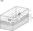
- FIG. 1 3 is a schematic three-dimensional representation of a deposit heater 1, which comprises a first and a second alternator 21, 22 for operating a conductor loop 4.
- the conductor loop 4 is at least partially introduced into a soil 46 of the deposit.
- the soil 46 comprises a hydrocarbon-containing substance, that is to say hydrocarbons to be transported, for example heavy oils, heavy oils, bitumen, oil sands and / or oil shale.
- the soil 46 may comprise a geological formation and / or a hydrocarbon-containing earth layer 42, in particular a plurality of earth layers 41,..., 43.
- the conductor loop 4 extends at least through and / or within a layer of earth 42 which contains the hydrocarbons to be transported, especially heavy oils, heavy oils, bitumen, oil sands or oil shale deposits.
- the hydrocarbonaceous earth layer 42 is surrounded by an overlying earth layer 41 and an underlying earth layer 43.
- Soil 46 comprises said earth layers 41, ..., 43.
- the conductor loop 4 forms an inductor 4, wherein the conductor loop 4, for example, at a depth of 50 m to 85 m, is introduced into the soil 46.
- the conductor loop 4 for forming an electrical resonant circuit, which is provided for reactive power compensation, a plurality of capacitors.
- the conductor loop 4 has a first and a second conductor section 44, 45.
- the first conductor portion 44 extends from the first alternator 21 to the second alternator 22.
- the second conductor portion 45 extends from the second alternator 22 back to the first alternator 21.
- the first and second conductor portions 44, 45 form the conductor loop 4.
- the first AC generator 21 is arranged in a first region 31 and the second AC generator 22 in a second region 32 of the conductor loop 4.
- the first and second conductor sections 44, 45 reach their greatest distance, for example of 50 m, in the earth layer 42, which has the hydrocarbons to be conveyed.
- the first and second alternators 21, 22 are disposed outside of the soil 46 and within an air layer 40 surrounding the reservoir 1.
- the first and second alternators 21, 22 are operated in phase-locked mode, that is to say that the phase difference between the first alternating current generated by the first alternating-current generator 21 and the second alternating-current generated by the second alternating-current generator 22 is not or only slightly in time varied.
- a fixed phase difference of 0 ° or 180 °, depending on the polarity of the first and second alternator 21, 22, an advantage.
- the alternating currents generated by the first and second alternators 21, 22 have the same frequency and current amplitude.
- the first and second alternators 21, 22 have approximately the same voltage amplitude, wherein different voltage amplitudes may be provided.
- the conductor loop 4 can be energized by means of more than two alternators. This advantageously further reduces the respective voltage amplitudes at the AC generators and in the conductor sections between the AC generators.
- N alternators are used, the electrical demand on the insulation of the conductor loop 4 against the ground 46 may decrease by a factor of 1 / N, if the effective voltage is higher than the reactive voltage of the respective conductor section between each two alternators.
- N is a natural number greater than or equal to two.
- At least a portion of the N alternators may be disposed within the soil 46.
- losses for example conversion losses of frequency converters arranged in the alternators, are advantageously delivered to the ground 46.
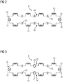
- FIG. 2 shows a schematic electrical equivalent circuit diagram of the conductor loop 4 FIG. 1 ,
- the conductor loop 4 comprises a plurality of capacitors 52.
- the inductors 51 are formed by the conductor loop 4 itself.
- the conductor loop 4 is in each case acted upon by means of the alternating current generators 21, 22 in each case with an alternating current.
- the capacitors 52 and inductors 51 forms an electrical series resonant circuit with a predetermined by the capacitors 52 and inductors 51 resonant frequency. It is advantageous to operate the first and second alternators 21, 22 at the resonant frequency of said series electrical oscillator. This results in a particularly advantageous reactive power compensation.
- the first and second alternators 21, 22 are arranged symmetrically with respect to the conductor length of the conductor loop 4, that is to say that the first conductor section 44 has substantially the same conductor length as the second conductor section 45.
- FIG. 3 a schematic electrical equivalent circuit of a conductor loop 4 is shown, which is acted upon in four areas 31, ..., 34 each with an alternating current.
- the conductor loop 4 with a first, second, third and fourth alternator 21, ..., 24 is electrically coupled.
- the lying between each two alternators conductor sections preferably have the same conductor length.
- the alternators 21,..., 24 are arranged symmetrically along the conductor loop 4. They thus divide the conductor loop 4 in the same length conductor sections.
- the conductor loop 4 has a plurality of capacitors 52 and inductors 51 for forming an electrical series resonant circuit.
- the third and fourth alternators 33, 34 may preferably be arranged in the ground 46, that is to say underground.
- the conductor loop 4 may be electrically coupled to more than four alternators. In other words, there is an N-fold energization of the conductor loop 4. Thus, the electrical requirement for the insulation of the conductor loop 4 against the ground 46 can be reduced by a factor of 1 / N.
Landscapes
- Life Sciences & Earth Sciences (AREA)
- Engineering & Computer Science (AREA)
- Geology (AREA)
- Mining & Mineral Resources (AREA)
- Physics & Mathematics (AREA)
- Environmental & Geological Engineering (AREA)
- Fluid Mechanics (AREA)
- General Life Sciences & Earth Sciences (AREA)
- Geochemistry & Mineralogy (AREA)
- Electromagnetism (AREA)
- General Induction Heating (AREA)
- Road Paving Machines (AREA)
Claims (14)
- Chauffage (1) de gisement pour chauffer par induction un terrain (46), qui comprend au moins un premier et un deuxième générateur 21, 22) de courant alternatif et une boucle (4) conductrice électrique disposée, au moins en partie, au sein du terrain (46), caractérisé en ce que la boucle (4) conductrice est couplée électriquement au premier et au deuxième générateur (21, 22) de courant alternatif, de manière à ce que la boucle (4) conductrice puisse, dans une première partie (31), être alimentée en un premier courant alternatif au moyen du premier générateur (21) de courant alternatif et, dans une deuxième partie (32), être alimentée en un deuxième courant alternatif au moyen du deuxième générateur (22) de courant alternatif.
- Chauffage (1) de gisement suivant la revendication 1, caractérisé en ce que la première et la deuxième parties (31, 32) sont disjointes le long de la boucle (4) conductrice.
- Chauffage (1) de gisement suivant la revendication 1 ou 2, caractérisé en ce que le premier et le deuxième générateurs (21, 22) de courant alternatif sont disposés à l'extérieur du terrain (46).
- Chauffage (1) de gisement suivant la revendication 1 ou 2, caractérisé en ce que le premier générateur (21) de courant alternatif est disposé à l'extérieur et le deuxième générateur (22) de courant alternatif à l'intérieur du terrain (46).
- Chauffage (1) de gisement suivant l'une des revendications précédentes, caractérisé en ce que les tronçons (44, 45) conducteurs de la boucle (4) conductrice, qui sont disposés entre le premier et le deuxième générateur (21, 22) de courant alternatif, sont constitués pareillement en ce qui concerne leur longueur de conducteur.
- Chauffage (1) de gisement suivant l'une des revendications précédentes, caractérisé en ce que le premier et/ou le deuxième générateur(s) (21, 22) de courant alternatif comprennent/comprend un convertisseur de fréquence.
- Chauffage (1) de gisement suivant l'une des revendications précédentes, caractérisé en ce que le premier et le deuxième générateurs (21, 22) de courant alternatif sont à une distance d'au moins 100 m.
- Procédé pour faire fonctionner un chauffage (1) de gisement, dans lequel un premier générateur (21) de courant alternatif produit un premier courant alternatif et un deuxième générateur (22) de courant alternatif, un deuxième courant alternatif, et dans lequel on alimente une boucle (4) conductrice disposée, au moins en partie, au sein d'un terrain (46) dans une première partie (31) en le premier courant alternatif et dans une deuxième partie (32) en le deuxième courant alternatif.
- Procédé suivant la revendication 8, dans lequel on fait fonctionner le premier et le deuxième générateur (21, 22) de courant alternatif d'une manière couplée en phase.
- Procédé suivant la revendication 8 ou 9, dans lequel on produit le premier et le deuxième courant alternatif à la même fréquence.
- Procédé suivant l'une des revendications 8 à 10, dans lequel on produit le premier et le deuxième courant alternatif à la même amplitude de tension.
- Procédé suivant l'une des revendications 8 à 11, dans lequel on produit le premier et le deuxième courant alternatif à une fréquence dans la plage de 10 kHz à 200 kHz.
- Procédé suivant l'une des revendications 8 à 12, dans lequel on produit le premier et le deuxième courant alternatif à une amplitude de tension d'au moins 10 kV.
- Utilisation d'un chauffage (1) de gisement sur l'une ou plusieurs des revendications 1 à 7, pour diminuer la viscosité d'une substance hydrocarbonée, qui se trouve dans un terrain (46).
Applications Claiming Priority (2)
| Application Number | Priority Date | Filing Date | Title |
|---|---|---|---|
| DE102014223621.5A DE102014223621A1 (de) | 2014-11-19 | 2014-11-19 | Lagerstättenheizung |
| PCT/EP2015/075915 WO2016078934A1 (fr) | 2014-11-19 | 2015-11-06 | Chauffage de gisement |
Publications (2)
| Publication Number | Publication Date |
|---|---|
| EP3204596A1 EP3204596A1 (fr) | 2017-08-16 |
| EP3204596B1 true EP3204596B1 (fr) | 2018-12-26 |
Family
ID=54545102
Family Applications (1)
| Application Number | Title | Priority Date | Filing Date |
|---|---|---|---|
| EP15794866.2A Not-in-force EP3204596B1 (fr) | 2014-11-19 | 2015-11-06 | Chauffage de gisement |
Country Status (6)
| Country | Link |
|---|---|
| US (1) | US20170328175A1 (fr) |
| EP (1) | EP3204596B1 (fr) |
| CA (1) | CA2968147C (fr) |
| DE (1) | DE102014223621A1 (fr) |
| RU (1) | RU2673091C1 (fr) |
| WO (1) | WO2016078934A1 (fr) |
Family Cites Families (47)
| Publication number | Priority date | Publication date | Assignee | Title |
|---|---|---|---|---|
| US3388324A (en) * | 1965-09-23 | 1968-06-11 | Schlumberger Technology Corp | Electrode array methods and apparatus, with undesired induced voltage cancellation, for investigating earth formations |
| DE2615204A1 (de) * | 1976-04-08 | 1977-10-27 | Still Gmbh | Schaltung fuer die nutzbremsung eines gleichstormreihenschlussmotors |
| CA1095400A (fr) * | 1976-05-03 | 1981-02-10 | Howard J. Rowland | Traitement sur place de gisements de matieres organiques |
| US4275310A (en) * | 1980-02-27 | 1981-06-23 | Summers William A | Peak power generation |
| US4651019A (en) * | 1984-11-16 | 1987-03-17 | Pennsylvania Power & Light Company | Dual fueled thermoelectric generator |
| US4608619A (en) * | 1985-03-18 | 1986-08-26 | General Motors Corporation | Ground fault voltage limiting for a locomotive electric traction motor |
| US5065819A (en) * | 1990-03-09 | 1991-11-19 | Kai Technologies | Electromagnetic apparatus and method for in situ heating and recovery of organic and inorganic materials |
| US6124646A (en) * | 1998-02-11 | 2000-09-26 | Alliedsignal Inc. | Aircraft air conditioning system including electric generator for providing AC power having limited frequency range |
| US5939800A (en) * | 1998-02-11 | 1999-08-17 | Alliedsignal Inc. | Aircraft electrical power system including air conditioning system generator |
| US7633172B2 (en) * | 2003-06-06 | 2009-12-15 | Pentadyne Power Corporation | Three plus three phase flywheel power supply |
| US7109622B2 (en) * | 2003-06-06 | 2006-09-19 | Pentadyne Power Corporation | Flywheel system with synchronous reluctance and permanent magnet generators |
| US8030787B2 (en) * | 2003-06-06 | 2011-10-04 | Beaver Aerospace And Defense, Inc. | Mbackup flywheel power supply |
| US7126236B2 (en) * | 2005-03-15 | 2006-10-24 | General Electric Company | Methods and apparatus for pitch control power conversion |
| US7484561B2 (en) * | 2006-02-21 | 2009-02-03 | Pyrophase, Inc. | Electro thermal in situ energy storage for intermittent energy sources to recover fuel from hydro carbonaceous earth formations |
| EP2010754A4 (fr) * | 2006-04-21 | 2016-02-24 | Shell Int Research | Ajustement de compositions d'alliages pour obtenir des proprietes choisies dans des systemes de chauffage a temperature limitee |
| DE102007040606B3 (de) * | 2007-08-27 | 2009-02-26 | Siemens Ag | Verfahren und Vorrichtung zur in situ-Förderung von Bitumen oder Schwerstöl |
| DE102007008292B4 (de) * | 2007-02-16 | 2009-08-13 | Siemens Ag | Vorrichtung und Verfahren zur In-Situ-Gewinnung einer kohlenwasserstoffhaltigen Substanz unter Herabsetzung deren Viskosität aus einer unterirdischen Lagerstätte |
| GB2449651A (en) * | 2007-05-29 | 2008-12-03 | Ultra Electronics Ltd | Power control system to reduce imbalances |
| DE102007036832B4 (de) * | 2007-08-03 | 2009-08-20 | Siemens Ag | Vorrichtung zur In-Situ-Gewinnung einer kohlenwasserstoffhaltigen Substanz |
| DE102008022176A1 (de) * | 2007-08-27 | 2009-11-12 | Siemens Aktiengesellschaft | Vorrichtung zur "in situ"-Förderung von Bitumen oder Schwerstöl |
| US7687927B2 (en) * | 2007-11-21 | 2010-03-30 | The Boeing Company | Electrical systems architecture for an aircraft, and related operating methods |
| DE102008062326A1 (de) * | 2008-03-06 | 2009-09-17 | Siemens Aktiengesellschaft | Anordnung zur induktiven Heizung von Ölsand- und Schwerstöllagerstätten mittels stromführender Leiter |
| CA2723447C (fr) * | 2008-05-05 | 2013-11-12 | Siemens Aktiengesellschaft | Procede et dispositif d'exploitation "in situ" de bitumes ou d'huile extra-lourde |
| US20090278408A1 (en) * | 2008-05-06 | 2009-11-12 | Cioffi Alfonso J | Integrated dc power system with one or more fuel cells |
| DE102008044953A1 (de) * | 2008-08-29 | 2010-03-04 | Siemens Aktiengesellschaft | Anlage zur In-Situ-Gewinnung einer kohlenstoffhaltigen Substanz |
| DE102008044955A1 (de) * | 2008-08-29 | 2010-03-04 | Siemens Aktiengesellschaft | Verfahren und Vorrichtung zur "in-situ"-Förderung von Bitumen oder Schwerstöl |
| AU2009303608B2 (en) * | 2008-10-13 | 2013-11-14 | Shell Internationale Research Maatschappij B.V. | Using self-regulating nuclear reactors in treating a subsurface formation |
| FR2948990A1 (fr) * | 2009-08-04 | 2011-02-11 | Mobile Comfort Holding | Dispositif thermodynamique multi-energie modulaire |
| US9422922B2 (en) * | 2009-08-28 | 2016-08-23 | Robert Sant'Anselmo | Systems, methods, and devices including modular, fixed and transportable structures incorporating solar and wind generation technologies for production of electricity |
| DE102010008779B4 (de) * | 2010-02-22 | 2012-10-04 | Siemens Aktiengesellschaft | Vorrichtung und Verfahren zur Gewinnung, insbesondere In-Situ-Gewinnung, einer kohlenstoffhaltigen Substanz aus einer unterirdischen Lagerstätte |
| DE102010020154B4 (de) * | 2010-03-03 | 2014-08-21 | Siemens Aktiengesellschaft | Verfahren und Vorrichtung zur "in-situ"-Förderung von Bitumen oder Schwerstöl |
| RU98042U1 (ru) * | 2010-04-15 | 2010-09-27 | Общество с ограниченной ответственностью "Научно-Производственное Предприятие "МАГНИТРОН" | Установка для питания погружного электродвигателя и/или нагрева скважинной жидкости |
| US9097182B2 (en) * | 2010-08-05 | 2015-08-04 | General Electric Company | Thermal control system for fault detection and mitigation within a power generation system |
| US8789599B2 (en) * | 2010-09-20 | 2014-07-29 | Harris Corporation | Radio frequency heat applicator for increased heavy oil recovery |
| DE102010043529B4 (de) * | 2010-09-27 | 2013-01-31 | Siemens Aktiengesellschaft | Vorrichtung und Verfahren zur Verwendung der Vorrichtung zur "in situ"-Förderung von Bitumen oder Schwerstöl aus Ölsand-Lagerstätten |
| US8453739B2 (en) * | 2010-11-19 | 2013-06-04 | Harris Corporation | Triaxial linear induction antenna array for increased heavy oil recovery |
| US8701760B2 (en) * | 2011-06-17 | 2014-04-22 | Harris Corporation | Electromagnetic heat treatment providing enhanced oil recovery |
| US20140005844A1 (en) * | 2011-09-07 | 2014-01-02 | Eric William Newcomb | System, method and apparatus providing power generation and demand management using a thermal hydraulic generator |
| DE102012000092B4 (de) * | 2012-02-24 | 2014-08-21 | Siemens Aktiengesellschaft | Vorrichtung und Verfahren zur Gewinnung von kohlenstoffhaltigen Substanzen aus Ölsanden |
| US9157303B2 (en) * | 2012-02-01 | 2015-10-13 | Harris Corporation | Hydrocarbon resource heating apparatus including upper and lower wellbore RF radiators and related methods |
| DE102012014658B4 (de) * | 2012-07-24 | 2014-08-21 | Siemens Aktiengesellschaft | Vorrichtung und Verfahren zur Gewinnung von kohlenstoffhaltigen Substanzen aus Ölsand |
| US9513648B2 (en) * | 2012-07-31 | 2016-12-06 | Causam Energy, Inc. | System, method, and apparatus for electric power grid and network management of grid elements |
| DE102012223559A1 (de) * | 2012-09-28 | 2014-05-15 | Siemens Aktiengesellschaft | Induktor zur Heizung von Schweröl- und Ölsandlagerstätten |
| RU2015126797A (ru) * | 2012-12-06 | 2017-01-12 | Сименс Акциенгезелльшафт | Система и способ введения тепла в геологическую формацию при помощи электромагнитной индукции |
| RU2659628C1 (ru) * | 2014-02-03 | 2018-07-03 | ДЭНИЕЛ МЕЖЕМЕНТ энд КОНТРОЛ, ИНК. | Предохранительный клапан с индикацией положения |
| WO2015191840A1 (fr) * | 2014-06-11 | 2015-12-17 | 540 Grid Solutions, Llc | Système de suppression de surtension pour moyenne et haute tension |
| US10211667B2 (en) * | 2014-10-03 | 2019-02-19 | Piller Usa, Inc. | Uninterrupted power supply systems and methods |
-
2014
- 2014-11-19 DE DE102014223621.5A patent/DE102014223621A1/de not_active Withdrawn
-
2015
- 2015-11-06 CA CA2968147A patent/CA2968147C/fr not_active Expired - Fee Related
- 2015-11-06 RU RU2017121088A patent/RU2673091C1/ru not_active IP Right Cessation
- 2015-11-06 EP EP15794866.2A patent/EP3204596B1/fr not_active Not-in-force
- 2015-11-06 WO PCT/EP2015/075915 patent/WO2016078934A1/fr not_active Ceased
- 2015-11-06 US US15/527,583 patent/US20170328175A1/en not_active Abandoned
Non-Patent Citations (1)
| Title |
|---|
| None * |
Also Published As
| Publication number | Publication date |
|---|---|
| CA2968147C (fr) | 2018-09-25 |
| EP3204596A1 (fr) | 2017-08-16 |
| WO2016078934A1 (fr) | 2016-05-26 |
| RU2673091C1 (ru) | 2018-11-22 |
| DE102014223621A1 (de) | 2016-05-19 |
| CA2968147A1 (fr) | 2016-05-26 |
| US20170328175A1 (en) | 2017-11-16 |
Similar Documents
| Publication | Publication Date | Title |
|---|---|---|
| DE102007040605B3 (de) | Vorrichtung zur "in situ"-Förderung von Bitumen oder Schwerstöl | |
| WO2009027305A2 (fr) | Dispositif d'extraction in situ de bitume et d'huile très lourde | |
| EP2315910B1 (fr) | Installation pour une extraction in situ d'une substance contenant du carbone | |
| EP2250858A1 (fr) | Agencement de chauffage inductif des gisements de sable pétrolifère et de pétrole ultra lourd à l'aide de conducteurs électriques | |
| WO2009135806A1 (fr) | Procédé et dispositif d'exploitation "in situ" de bitumes ou d'huile extra-lourde | |
| EP2925956B1 (fr) | Dispositif blindé à plusieurs paires en tant que ligne d'alimentation d'une boucle de chauffe par induction dans des gisements d'huiles lourdes | |
| EP3204596B1 (fr) | Chauffage de gisement | |
| DE102012223559A1 (de) | Induktor zur Heizung von Schweröl- und Ölsandlagerstätten | |
| DE102010020154B4 (de) | Verfahren und Vorrichtung zur "in-situ"-Förderung von Bitumen oder Schwerstöl | |
| EP2633153A1 (fr) | Procédé d'exploitation « in situ » de bitumes ou d'huile extra lourde à partir de gisements de sables bitumineux en tant que réservoir | |
| DE102010043529B4 (de) | Vorrichtung und Verfahren zur Verwendung der Vorrichtung zur "in situ"-Förderung von Bitumen oder Schwerstöl aus Ölsand-Lagerstätten | |
| EP3005831B1 (fr) | Inducteur pour chauffage par induction | |
| DE102015210701A1 (de) | Heizvorrichtung zur induktiven Heizung einer Kohlenwasserstofflagerstätte mit Filterelement, Anordnung sowie Verfahren | |
| DE102015208056A1 (de) | Heizvorrichtung zur induktiven Heizung einer Kohlenwasserstofflagerstätte | |
| DE102015208110A1 (de) | Heizvorrichtung zur induktiven Heizung einer Kohlenwasserstofflagerstätte | |
| DE102013008216A1 (de) | Verfahren zum Einleiten von Wasserdampf und/oder Warmwasser in eine Öllagerstätte | |
| DE102015210689A1 (de) | Heizvorrichtung zur induktiven Heizung einer Kohlenwasserstofflagerstätte mit in Reihe geschalteten Leitereinrichtungen, Anordnung sowie Verfahren | |
| DE102015215463A1 (de) | Heizvorrichtung zur induktiven Heizung einer Ölsandlagerstätte und/oder einer Ölschieferlagerstätte und/oder einer Bitumenlagerstätte und/oder einer Schweröllagerstätte | |
| EP3084121A1 (fr) | Procédé d'introduction d'une boucle d'inducteur dans une formation rocheuse | |
| WO2015090649A1 (fr) | Procédé d'introduction d'une boucle d'inducteur dans une formation rocheuse | |
| WO2016091584A1 (fr) | Dispositif de chauffage par induction de un gisement de sable bitumineux et/ou un gisement de schiste bitumineux et/ou un gisement de bitume et/ou un gisement d'huile lourde |
Legal Events
| Date | Code | Title | Description |
|---|---|---|---|
| STAA | Information on the status of an ep patent application or granted ep patent |
Free format text: STATUS: THE INTERNATIONAL PUBLICATION HAS BEEN MADE |
|
| PUAI | Public reference made under article 153(3) epc to a published international application that has entered the european phase |
Free format text: ORIGINAL CODE: 0009012 |
|
| STAA | Information on the status of an ep patent application or granted ep patent |
Free format text: STATUS: REQUEST FOR EXAMINATION WAS MADE |
|
| 17P | Request for examination filed |
Effective date: 20170511 |
|
| AK | Designated contracting states |
Kind code of ref document: A1 Designated state(s): AL AT BE BG CH CY CZ DE DK EE ES FI FR GB GR HR HU IE IS IT LI LT LU LV MC MK MT NL NO PL PT RO RS SE SI SK SM TR |
|
| AX | Request for extension of the european patent |
Extension state: BA ME |
|
| RAP1 | Party data changed (applicant data changed or rights of an application transferred) |
Owner name: SIEMENS AKTIENGESELLSCHAFT |
|
| DAV | Request for validation of the european patent (deleted) | ||
| DAX | Request for extension of the european patent (deleted) | ||
| GRAP | Despatch of communication of intention to grant a patent |
Free format text: ORIGINAL CODE: EPIDOSNIGR1 |
|
| STAA | Information on the status of an ep patent application or granted ep patent |
Free format text: STATUS: GRANT OF PATENT IS INTENDED |
|
| INTG | Intention to grant announced |
Effective date: 20180704 |
|
| GRAS | Grant fee paid |
Free format text: ORIGINAL CODE: EPIDOSNIGR3 |
|
| GRAA | (expected) grant |
Free format text: ORIGINAL CODE: 0009210 |
|
| STAA | Information on the status of an ep patent application or granted ep patent |
Free format text: STATUS: THE PATENT HAS BEEN GRANTED |
|
| AK | Designated contracting states |
Kind code of ref document: B1 Designated state(s): AL AT BE BG CH CY CZ DE DK EE ES FI FR GB GR HR HU IE IS IT LI LT LU LV MC MK MT NL NO PL PT RO RS SE SI SK SM TR |
|
| REG | Reference to a national code |
Ref country code: GB Ref legal event code: FG4D Free format text: NOT ENGLISH |
|
| REG | Reference to a national code |
Ref country code: CH Ref legal event code: EP |
|
| REG | Reference to a national code |
Ref country code: AT Ref legal event code: REF Ref document number: 1081682 Country of ref document: AT Kind code of ref document: T Effective date: 20190115 |
|
| REG | Reference to a national code |
Ref country code: DE Ref legal event code: R096 Ref document number: 502015007470 Country of ref document: DE |
|
| REG | Reference to a national code |
Ref country code: IE Ref legal event code: FG4D Free format text: LANGUAGE OF EP DOCUMENT: GERMAN |
|
| PG25 | Lapsed in a contracting state [announced via postgrant information from national office to epo] |
Ref country code: FI Free format text: LAPSE BECAUSE OF FAILURE TO SUBMIT A TRANSLATION OF THE DESCRIPTION OR TO PAY THE FEE WITHIN THE PRESCRIBED TIME-LIMIT Effective date: 20181226 Ref country code: NO Free format text: LAPSE BECAUSE OF FAILURE TO SUBMIT A TRANSLATION OF THE DESCRIPTION OR TO PAY THE FEE WITHIN THE PRESCRIBED TIME-LIMIT Effective date: 20190326 Ref country code: LT Free format text: LAPSE BECAUSE OF FAILURE TO SUBMIT A TRANSLATION OF THE DESCRIPTION OR TO PAY THE FEE WITHIN THE PRESCRIBED TIME-LIMIT Effective date: 20181226 Ref country code: HR Free format text: LAPSE BECAUSE OF FAILURE TO SUBMIT A TRANSLATION OF THE DESCRIPTION OR TO PAY THE FEE WITHIN THE PRESCRIBED TIME-LIMIT Effective date: 20181226 Ref country code: BG Free format text: LAPSE BECAUSE OF FAILURE TO SUBMIT A TRANSLATION OF THE DESCRIPTION OR TO PAY THE FEE WITHIN THE PRESCRIBED TIME-LIMIT Effective date: 20190326 Ref country code: LV Free format text: LAPSE BECAUSE OF FAILURE TO SUBMIT A TRANSLATION OF THE DESCRIPTION OR TO PAY THE FEE WITHIN THE PRESCRIBED TIME-LIMIT Effective date: 20181226 |
|
| REG | Reference to a national code |
Ref country code: NL Ref legal event code: MP Effective date: 20181226 |
|
| REG | Reference to a national code |
Ref country code: LT Ref legal event code: MG4D |
|
| PG25 | Lapsed in a contracting state [announced via postgrant information from national office to epo] |
Ref country code: AL Free format text: LAPSE BECAUSE OF FAILURE TO SUBMIT A TRANSLATION OF THE DESCRIPTION OR TO PAY THE FEE WITHIN THE PRESCRIBED TIME-LIMIT Effective date: 20181226 Ref country code: RS Free format text: LAPSE BECAUSE OF FAILURE TO SUBMIT A TRANSLATION OF THE DESCRIPTION OR TO PAY THE FEE WITHIN THE PRESCRIBED TIME-LIMIT Effective date: 20181226 Ref country code: SE Free format text: LAPSE BECAUSE OF FAILURE TO SUBMIT A TRANSLATION OF THE DESCRIPTION OR TO PAY THE FEE WITHIN THE PRESCRIBED TIME-LIMIT Effective date: 20181226 Ref country code: GR Free format text: LAPSE BECAUSE OF FAILURE TO SUBMIT A TRANSLATION OF THE DESCRIPTION OR TO PAY THE FEE WITHIN THE PRESCRIBED TIME-LIMIT Effective date: 20190327 |
|
| PG25 | Lapsed in a contracting state [announced via postgrant information from national office to epo] |
Ref country code: NL Free format text: LAPSE BECAUSE OF FAILURE TO SUBMIT A TRANSLATION OF THE DESCRIPTION OR TO PAY THE FEE WITHIN THE PRESCRIBED TIME-LIMIT Effective date: 20181226 |
|
| PG25 | Lapsed in a contracting state [announced via postgrant information from national office to epo] |
Ref country code: IT Free format text: LAPSE BECAUSE OF FAILURE TO SUBMIT A TRANSLATION OF THE DESCRIPTION OR TO PAY THE FEE WITHIN THE PRESCRIBED TIME-LIMIT Effective date: 20181226 Ref country code: ES Free format text: LAPSE BECAUSE OF FAILURE TO SUBMIT A TRANSLATION OF THE DESCRIPTION OR TO PAY THE FEE WITHIN THE PRESCRIBED TIME-LIMIT Effective date: 20181226 Ref country code: PL Free format text: LAPSE BECAUSE OF FAILURE TO SUBMIT A TRANSLATION OF THE DESCRIPTION OR TO PAY THE FEE WITHIN THE PRESCRIBED TIME-LIMIT Effective date: 20181226 Ref country code: PT Free format text: LAPSE BECAUSE OF FAILURE TO SUBMIT A TRANSLATION OF THE DESCRIPTION OR TO PAY THE FEE WITHIN THE PRESCRIBED TIME-LIMIT Effective date: 20190426 Ref country code: CZ Free format text: LAPSE BECAUSE OF FAILURE TO SUBMIT A TRANSLATION OF THE DESCRIPTION OR TO PAY THE FEE WITHIN THE PRESCRIBED TIME-LIMIT Effective date: 20181226 |
|
| PG25 | Lapsed in a contracting state [announced via postgrant information from national office to epo] |
Ref country code: RO Free format text: LAPSE BECAUSE OF FAILURE TO SUBMIT A TRANSLATION OF THE DESCRIPTION OR TO PAY THE FEE WITHIN THE PRESCRIBED TIME-LIMIT Effective date: 20181226 Ref country code: SK Free format text: LAPSE BECAUSE OF FAILURE TO SUBMIT A TRANSLATION OF THE DESCRIPTION OR TO PAY THE FEE WITHIN THE PRESCRIBED TIME-LIMIT Effective date: 20181226 Ref country code: IS Free format text: LAPSE BECAUSE OF FAILURE TO SUBMIT A TRANSLATION OF THE DESCRIPTION OR TO PAY THE FEE WITHIN THE PRESCRIBED TIME-LIMIT Effective date: 20190426 Ref country code: SM Free format text: LAPSE BECAUSE OF FAILURE TO SUBMIT A TRANSLATION OF THE DESCRIPTION OR TO PAY THE FEE WITHIN THE PRESCRIBED TIME-LIMIT Effective date: 20181226 Ref country code: EE Free format text: LAPSE BECAUSE OF FAILURE TO SUBMIT A TRANSLATION OF THE DESCRIPTION OR TO PAY THE FEE WITHIN THE PRESCRIBED TIME-LIMIT Effective date: 20181226 |
|
| REG | Reference to a national code |
Ref country code: DE Ref legal event code: R097 Ref document number: 502015007470 Country of ref document: DE |
|
| PG25 | Lapsed in a contracting state [announced via postgrant information from national office to epo] |
Ref country code: DK Free format text: LAPSE BECAUSE OF FAILURE TO SUBMIT A TRANSLATION OF THE DESCRIPTION OR TO PAY THE FEE WITHIN THE PRESCRIBED TIME-LIMIT Effective date: 20181226 |
|
| PLBE | No opposition filed within time limit |
Free format text: ORIGINAL CODE: 0009261 |
|
| STAA | Information on the status of an ep patent application or granted ep patent |
Free format text: STATUS: NO OPPOSITION FILED WITHIN TIME LIMIT |
|
| 26N | No opposition filed |
Effective date: 20190927 |
|
| PG25 | Lapsed in a contracting state [announced via postgrant information from national office to epo] |
Ref country code: SI Free format text: LAPSE BECAUSE OF FAILURE TO SUBMIT A TRANSLATION OF THE DESCRIPTION OR TO PAY THE FEE WITHIN THE PRESCRIBED TIME-LIMIT Effective date: 20181226 |
|
| PG25 | Lapsed in a contracting state [announced via postgrant information from national office to epo] |
Ref country code: TR Free format text: LAPSE BECAUSE OF FAILURE TO SUBMIT A TRANSLATION OF THE DESCRIPTION OR TO PAY THE FEE WITHIN THE PRESCRIBED TIME-LIMIT Effective date: 20181226 |
|
| REG | Reference to a national code |
Ref country code: DE Ref legal event code: R119 Ref document number: 502015007470 Country of ref document: DE |
|
| REG | Reference to a national code |
Ref country code: CH Ref legal event code: PL |
|
| PG25 | Lapsed in a contracting state [announced via postgrant information from national office to epo] |
Ref country code: MC Free format text: LAPSE BECAUSE OF FAILURE TO SUBMIT A TRANSLATION OF THE DESCRIPTION OR TO PAY THE FEE WITHIN THE PRESCRIBED TIME-LIMIT Effective date: 20181226 Ref country code: CH Free format text: LAPSE BECAUSE OF NON-PAYMENT OF DUE FEES Effective date: 20191130 Ref country code: LI Free format text: LAPSE BECAUSE OF NON-PAYMENT OF DUE FEES Effective date: 20191130 Ref country code: LU Free format text: LAPSE BECAUSE OF NON-PAYMENT OF DUE FEES Effective date: 20191106 |
|
| REG | Reference to a national code |
Ref country code: BE Ref legal event code: MM Effective date: 20191130 |
|
| GBPC | Gb: european patent ceased through non-payment of renewal fee |
Effective date: 20191106 |
|
| PG25 | Lapsed in a contracting state [announced via postgrant information from national office to epo] |
Ref country code: FR Free format text: LAPSE BECAUSE OF NON-PAYMENT OF DUE FEES Effective date: 20191130 Ref country code: DE Free format text: LAPSE BECAUSE OF NON-PAYMENT OF DUE FEES Effective date: 20200603 Ref country code: IE Free format text: LAPSE BECAUSE OF NON-PAYMENT OF DUE FEES Effective date: 20191106 Ref country code: GB Free format text: LAPSE BECAUSE OF NON-PAYMENT OF DUE FEES Effective date: 20191106 |
|
| PG25 | Lapsed in a contracting state [announced via postgrant information from national office to epo] |
Ref country code: BE Free format text: LAPSE BECAUSE OF NON-PAYMENT OF DUE FEES Effective date: 20191130 |
|
| PG25 | Lapsed in a contracting state [announced via postgrant information from national office to epo] |
Ref country code: CY Free format text: LAPSE BECAUSE OF FAILURE TO SUBMIT A TRANSLATION OF THE DESCRIPTION OR TO PAY THE FEE WITHIN THE PRESCRIBED TIME-LIMIT Effective date: 20181226 |
|
| PG25 | Lapsed in a contracting state [announced via postgrant information from national office to epo] |
Ref country code: HU Free format text: LAPSE BECAUSE OF FAILURE TO SUBMIT A TRANSLATION OF THE DESCRIPTION OR TO PAY THE FEE WITHIN THE PRESCRIBED TIME-LIMIT; INVALID AB INITIO Effective date: 20151106 Ref country code: MT Free format text: LAPSE BECAUSE OF FAILURE TO SUBMIT A TRANSLATION OF THE DESCRIPTION OR TO PAY THE FEE WITHIN THE PRESCRIBED TIME-LIMIT Effective date: 20181226 |
|
| REG | Reference to a national code |
Ref country code: AT Ref legal event code: MM01 Ref document number: 1081682 Country of ref document: AT Kind code of ref document: T Effective date: 20201106 |
|
| PG25 | Lapsed in a contracting state [announced via postgrant information from national office to epo] |
Ref country code: AT Free format text: LAPSE BECAUSE OF NON-PAYMENT OF DUE FEES Effective date: 20201106 |
|
| PG25 | Lapsed in a contracting state [announced via postgrant information from national office to epo] |
Ref country code: MK Free format text: LAPSE BECAUSE OF FAILURE TO SUBMIT A TRANSLATION OF THE DESCRIPTION OR TO PAY THE FEE WITHIN THE PRESCRIBED TIME-LIMIT Effective date: 20181226 |