EP3204597B1 - Vorrichtung zur energieerzeugung in einem fluidsystem - Google Patents
Vorrichtung zur energieerzeugung in einem fluidsystem Download PDFInfo
- Publication number
- EP3204597B1 EP3204597B1 EP15771946.9A EP15771946A EP3204597B1 EP 3204597 B1 EP3204597 B1 EP 3204597B1 EP 15771946 A EP15771946 A EP 15771946A EP 3204597 B1 EP3204597 B1 EP 3204597B1
- Authority
- EP
- European Patent Office
- Prior art keywords
- fluid
- flow pathway
- turbine
- flow
- rotor
- Prior art date
- Legal status (The legal status is an assumption and is not a legal conclusion. Google has not performed a legal analysis and makes no representation as to the accuracy of the status listed.)
- Active
Links
Images

Classifications
-
- E—FIXED CONSTRUCTIONS
- E21—EARTH OR ROCK DRILLING; MINING
- E21B—EARTH OR ROCK DRILLING; OBTAINING OIL, GAS, WATER, SOLUBLE OR MELTABLE MATERIALS OR A SLURRY OF MINERALS FROM WELLS
- E21B41/00—Equipment or details not covered by groups E21B15/00 - E21B40/00
- E21B41/0085—Adaptations of electric power generating means for use in boreholes
-
- E—FIXED CONSTRUCTIONS
- E21—EARTH OR ROCK DRILLING; MINING
- E21B—EARTH OR ROCK DRILLING; OBTAINING OIL, GAS, WATER, SOLUBLE OR MELTABLE MATERIALS OR A SLURRY OF MINERALS FROM WELLS
- E21B44/00—Automatic control systems specially adapted for drilling operations, i.e. self-operating systems which function to carry out or modify a drilling operation without intervention of a human operator, e.g. computer-controlled drilling systems; Systems specially adapted for monitoring a plurality of drilling variables or conditions
-
- Y—GENERAL TAGGING OF NEW TECHNOLOGICAL DEVELOPMENTS; GENERAL TAGGING OF CROSS-SECTIONAL TECHNOLOGIES SPANNING OVER SEVERAL SECTIONS OF THE IPC; TECHNICAL SUBJECTS COVERED BY FORMER USPC CROSS-REFERENCE ART COLLECTIONS [XRACs] AND DIGESTS
- Y02—TECHNOLOGIES OR APPLICATIONS FOR MITIGATION OR ADAPTATION AGAINST CLIMATE CHANGE
- Y02E—REDUCTION OF GREENHOUSE GAS [GHG] EMISSIONS, RELATED TO ENERGY GENERATION, TRANSMISSION OR DISTRIBUTION
- Y02E10/00—Energy generation through renewable energy sources
- Y02E10/20—Hydro energy
Definitions
- Embodiments described herein relate to power generation in a fluid system and in particular to apparatus for use in fluid flow systems for extracting, such as are found in the oil and gas exploration and production industry.
- Systems associated with fluid flow systems, and their monitoring and control may require a power source.
- a power source for example, in the oil and gas industry, throughout the lifetime of a well, it may be required to supply power to apparatus in the well.
- powered systems can include, for example, actuation systems requiring mechanical operation such as flow control devices, chokes, valves, etc., sensors such as pressure sensors, communications systems, diagnostic systems, and the like.
- apparatus may be convenient for apparatus to be powered by a local power source. In some instances it may be impractical or impossible to supply power from the surface. Increasingly, placing of downhole components may conflict with future access requirements. For example, it may not be possible for power transmission cables to bypass packers. Apparatus may also become isolated, for example in an old branch of a multilateral well, or where topside installations are removed or abandoned.
- Power may be supplied locally from electrical cells or batteries introduced into a well.
- the operational life of the battery can be significantly reduced due to the challenging environmental conditions found downhole.
- power may be required over long periods of time, in some cases over the course of years, and current battery technology may not permit charge to be held for as long as may be required.
- WO2014/105053 discloses a bladeless generator carried by drilling string, and disposed to employ mud flow through the drill string.
- US2006/100968 discloses a method for distributing electricity to downhole tools including providing a downhole generator.
- US2013/153242 A1 describes in-riser power generation devices and methods utilized to generate power subsea to operate subsea devices of a subsea well system.
- a turbine power generator is located in fluid communication with a subsea fluid flow path of a subsea well system and the turbine power generator is operationally connected to a subsea power device.
- WO9956017 A2 describes a water driven impulse turbine having a barrel rotatably mounted upon an axle, with a plurality of runner blades extending from tangentially from said barrel. Side plates secure the runner blades on opposite sides thereof. A breastplate is maintained in concentric juxtaposition with the wheel so defined. A penstock is interposed between a water source and the breastplate to pass water into the runner blades.
- the turbine may consist of a plurality of axially interconnected wheel sections of similar or dissimilar nature to optimise performance.
- US2009/110485 A1 describes a method for selectively generating electrical power by using waste water gravity flow to generate electrical power, including attaching the ends of a water flow diversion pipe to a waste water pipe. At least some of the waste water flowing by gravity through the waste water pipe is diverted into and through the diversion pipe and back into the waste water pipe. An electrical power generator is driven to generate electrical power in response to the waste water flowing through the diversion pipe. At least a portion of the electrical power generated by the at least one electrical power generator is stored and can be trapped later to supplement the output of the electrical power generator.
- An aspect of the invention is directed to an apparatus for use in a fluid flow system, as defined by claim 1
- the body may comprise an eccentric mandrel.
- the body may comprise a connector, e.g. for connecting a tubular to an adjacent tubular, or to two adjacent tubulars (to each end of the body).
- the turbine may for example form part of or define a pup joint.
- the body may define the inlet and/or the outlet of the flow pathway.
- the outlet of the flow pathway may be configured to be placed in communication with the fluid channel, such that fluid flowing along the flow pathway may be returned to the channel, in use.
- the outlet may for example comprise a flapper valve, which may prevent fluid from flowing into the fluid channel against the flapper valve.
- the rotor may comprise one or more rotor blades, extending from a hub.
- One or more parts of the turbine may be formed integrally with the body.
- the body may define the fluid channel, or at least a portion of the fluid channel.
- the turbine may be configured so that fluid may flow past or through the rotor along the flow pathway obliquely to the rotation axis.
- the turbine may comprise more than one flow pathway, each having an inlet and an outlet.
- the turbine may be configured to operate bi-directionally.
- the turbine may be configured to extract energy from fluid flowing in either direction along the flow pathway or the fluid channel.
- the turbine may be configured for use with an existing or a standard tubular, such as oilfield tubing.
- the turbine may comprise an electrical rotor and stator.
- the stator may comprise a permanent magnet or one or more conductive coils.
- the rotor may comprise the other of a permanent magnet or one or more conductive coils.
- the turbine may comprise an energy storage arrangement.
- the turbine may be configured to be coupled to an energy storage arrangement.
- the energy storage arrangement may comprise an electrical or electrochemical storage arrangement, such as a chargeable cell or battery.
- the turbine may comprise an autonomous flow control arrangement.
- a standard tubular such as coiled tubing may be machined to form aperture through the walls of the tubular to the fluid channel, to be aligned with corresponding inlet/outlet of the flow pathway.
- the apparatus may comprise or be configured for connection to additional components, such a one or more inflow control devices, sensors, logging tools etc., or other powered downhole apparatus as known in the art.
- Energy may be supplied to one or more additional components from an energy storage arrangement. Energy may be supplied to one or more additional components by the turbine. Energy may be supplied when the turbine is rotating, or at a later time.
- Energy extracted or generated by the turbine may be utilised for example to operate downhole sensors, or downhole apparatus such as inflow control devices and the like.
- the apparatus may comprise more than one turbine. More than one turbine may be spaced apart axially on the body. More than one turbine may be circumferentially spaced apart around the body.
- the apparatus may be, or form part of, a downhole tool (e.g. a logging tool), a completion string, or a connector for connecting a length of tubular to another length of tubular.
- a downhole tool e.g. a logging tool
- completion string e.g. a completion string
- connector for connecting a length of tubular to another length of tubular.
- An aspect of the invention is directed to a method for extracting energy from fluid flowing along a fluid channel, as defined by appended claim 13.
- the method may comprise venting or discharging fluid from the outlet.
- the method comprises passing fluid from the flow pathway and into the fluid channel through the outlet from the flow pathway.
- the method may further comprise passing fluid from the fluid channel, along the flow pathway, and returning the fluid to the fluid channel through the outlet from the flow pathway.
- the method comprises returning the fluid to the fluid channel via the outlet which may be axially spaced apart from the inlet to the flow pathway. Fluid is returned to the fluid channel through the outlet which may be downstream of the inlet, in relation to the flow of fluid through the fluid channel.
- the method may further comprise passing fluid from the fluid channel through the outlet, past the rotor disposed in the flow pathway, and returning fluid to the fluid channel through the inlet.
- the rotor may thereby be rotated under the action of fluid flowing in the flow pathway, around the rotation axis.
- the method may comprise rotating the rotor around the rotation axis in a first direction when fluid is flowing along the flow pathway from the inlet to the outlet, and rotating the rotor around an opposite second direction when fluid is flowing along the flow pathway from the outlet to the inlet.
- the rotor may rotate in the same direction regardless of the direction of flow of fluid along the flow pathway.
- the method may comprise varying the speed and/or the pressure of fluid as it flows along the flow pathway.
- the speed and/or pressure of fluid may be varied by passing the fluid through a region of the flow pathway having reduced and/or an increased flow area.
- the method may comprise passing all, or only a portion of fluid flowing along the fluid channel through the flow pathway.
- the method may comprise varying the flow of fluid along the flow pathway.
- the method may comprise varying the proportion of fluid from the fluid channel which flows along the flow pathway.
- the method may comprise operating the flow control arrangement.
- the method may comprise detecting a change in the composition, temperature, pressure or flow rate of the fluid flowing through the fluid channel and consequently varying the flow of fluid along the flow pathway.
- the flow control arrangement may be operated to choke or stop flow through the flow pathway if a pressure above a threshold pressure is detected, or if water or a slug of gas in the fluid channel is detected.
- the method may comprise storing the extracted energy.
- the method may comprise charging an electrical cell or battery with electrical energy generated by rotation of the rotor (e.g. by electromagnetic induction).
- the method may comprise charging a fluid accumulator.
- the method may comprise placing an elastic member in tension or compression, using energy transmitted from the rotor (e.g. via a drive arrangement).
- the method may comprise operating the flow control arrangement (to restrict or prevent flow of fluid along the flow pathway) when the amount of stored energy exceeds a predetermined energy storage capacity.
- the stored energy may be used to power other apparatus in the fluid system, such as a downhole tool, an inflow control device, a sensor, and the like.
- the method may comprise directly utilizing the energy extracted by the turbine.
- Figure 1 shows a schematic cross sectional view of an example embodiment of apparatus for extracting and storing energy from fluid in a well (a fluid system), for use in powering apparatus in the well.
- a portion of production tubing 1 is shown in a well 3.
- the production tubing 1 has a bore 4 extending therethrough (a fluid channel), along an axis A.
- a zone 5 of the well 3 is isolated above and below a producing formation 7, between packer elements 9.
- the production tubing 1 includes an eccentric mandrel 11. Fluid flow from the isolated zone 5 into the production tubing 1 is regulated by an inflow control valve 12 mounted in the mandrel 11.
- the inflow control valve 12 includes a port 13 and a sliding sleeve 15, moveable (by way of an electromechanical actuator, shown in Figure 2 ) between a closed position, as shown in Figure 1 , in which the sleeve 15 blocks the port 13 and an open position in which the sleeve is withdrawn into the cavity 17, so that fluid may flow from the producing formation 7, to the isolated zone 5, through the port 13 and into the bore 4 of the production tubing 1.
- Electrical power required to move the sleeve 15 between the open and closed positions is supplied from a battery 19 mounted in the mandrel 11 (see Figure 2 ).
- a turbine 21 in accordance with an embodiment of the invention forms part of and is recessed within the mandrel 11.
- the turbine 21 does not intrude into the bore 4 of the tubing 1.
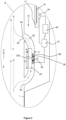
- FIG 2 shows a detailed schematic view of region B the mandrel 11 and the turbine 21.
- the turbine 21 has a flow pathway 30 extending from an inlet 32 communicating with the fluid channel (the bore 4) to an outlet 34.
- the outlet also communicates with the bore 4, however in alternative embodiments, the outlet may vent or be discharged to an outside of the turbine (e.g. into the well).
- the outlet 34 is axial spaced apart from the inlet 32, so that fluid flowing along the flow pathway 30 returns to the bore 4 through the outlet downstream of the inlet (in relation to fluid flow F).
- the flow pathway 30 is configured such that a minor portion f of the fluid flow F is directed into the flow pathway 30, and subsequently returned to the bore. Thus, flow along the fluid channel (bore 4) is substantially unaffected by the turbine 21.
- a rotor 23 is disposed in the flow pathway 30. Fluid flowing along the flow pathway 30 causes the rotor to rotate about the rotation axis R.
- the rotation axis R is oblique to the axis A along the bore 4. In the example shown, which does not form part of the invention, the axes are perpendicular to one another and intersect.
- the obliquely oriented rotation axis R provides for a compact arrangement of the turbine.
- the turbine 21 is required to accommodate the thickness C, rather than the greater diameter D, of the rotor 23. Accordingly, a larger diameter rotor may be accommodated within a given available radial thickness.
- the inlet 32 and the outlet 34 are spaced apart along the axis A of the tubular and are axially aligned such that the flow pathway 30 runs generally parallel to the axis A.
- the inlet and outlet may be spaced apart around the circumference of the tubular (for example to accommodate other apparatus).
- Alternative apparatus may include several turbines, which may be spaced apart axially or circumferentially.
- the turbine 23 spins around the rotation axis R, within an annular stator 36.
- An annular bearing 38 is provided between the rotor and the stator.
- the stator comprises electrical coils. Permanent magnets 40 are embedded within a hub portion 23a of the rotor extending into the stator 36. Thus, an electromotive force is generated when the rotor rotates around the rotation axis R, under the action of fluid flowing along the flow pathway 30.
- the stator 36 is electrically connected to a battery 19, which stores energy extracted by the turbine 21 from fluid flowing along the bore 4 and into the flow pathway 30. Under the control of a control unit 42, electrical energy from the battery 19 may be used to power an actuator 44 coupled to the sliding sleeve 15, so as to open and close the inflow control valve 12.
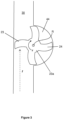
- FIG. 3 shows a schematic cross sectional view of the turbine 21 through the flow pathway 30, along the rotation axis R.
- the rotor 23 is a Pelton type rotor, having a hub portion 23a and (in the embodiment shown) four blades 24 extending from the hub portion.
- the rotor is offset from the flow pathway 30, such a part of the rotor 23 sits within a cavity 44 and a part of the rotor extends into the flow pathway itself.
- fluid flowing along the flow pathway in the direction f impinges upon the blades 24 to one side of the rotation axis Q and causes the rotor to rotate in the direction r.
- the blades are profiled so as to efficiently extract energy from fluid flowing along the flow pathway in the opposite direction (or alternatively, for fluid flowing in the opposite direction to preferentially flow to the other side of a turbine symmetrically disposed in the flow pathway).
- a turbine may be provided with any suitable type of rotor.
- the rotor 23 is an impingement based rotor
- a lift based rotor may also be used.
- a Darrieus type rotor may be capable of extracting energy from fluid flowing along the flow pathway in either direction.
- Turbine 21 is provided with a flow control arrangement at the outlet, in the form of a flapper valve 50, visible in Figure 2.
- Figure 2 shows the flapper valve in an open position.
- the flapper valve 50 is biased towards a closed position in which the outlet 34 is blocked. This serves two main functions. Firstly, in the event of fluid flowing in the opposite direction along the bore 4 (for example is mud or another fluid is pumped into the completion string 1), the flapper valve closes and so protects the turbine 21 from damage. Secondly, the flapper valve 50 serves to slightly narrow, or "choke", the flow pathway when the fluid flow F increases in pressure. The flapper valve thereby serves to reduce the proportion of the fluid flow entering the flow pathway, again protecting the turbine (or the battery) from damage in the event of a pressure surge.
- the inlet may also be provided with a flow control arrangement (which may be passive, or which may be powered by the battery).
- a flow control arrangement which may be passive, or which may be powered by the battery.
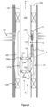
- FIG. 4 An alternative embodiment is shown in Figure 4 .
- Features in common with the embodiment shown in Figures 1-3 are provided with like numerals, incremented by 100.
- Figure 4 shows a tubular 101 comprising a mandrel 111 which extends around the tubular 101.
- a turbine 121 is mounted in the mandrel.
- the mandrel also comprises (three) further turbines 121a, radially spaced apart around the mandrel.
- the turbine 121 is operatively coupled to an inflow control valve 112.
- the other turbines 121a are coupled to other downhole apparatus (not shown).
- a part 122 of the turbine extends slightly into the bore 104.
- the turbine comprises a series of inlets 132, 132a and outlets 134, 134a on the frustoconical surfaces 160 and 161 of the inwardly extending part 122 of the mandrel 121, each associated with a flow pathway and a rotor of a turbine 121, 121a.
- the extension of the inlets into the fluid flow F along the channel assists in directing a portion of the fluid flow into the flow pathways of the turbines.
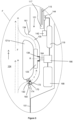
- Figure 5 shows a detail schematic view of region F, highlighted in Figure 4 , showing the turbine 121.
- FIG. 5 shows a detail schematic view of region F, highlighted in Figure 4 , showing the turbine 121.
- Features common to features shown in Figure 3 are provided with like reference numerals, incremented by 100.
- the rotor 123 is coupled via a drive arrangement, a drive shaft 164, to a compressor 166.
- the mandrel also comprises a fluid reservoir 168 and a fluid accumulator 119.
- the compressor is powered by the rotor 123 to pump and pressurise fluid (e.g. compressed air) into the accumulator 119.
- a pneumatic (or in alternative embodiments hydraulic) actuator 144 may be actuated using compressed fluid from the accumulator 119, so as to move the sleeve 115 and open and close the inflow valve 112.
- the inlet 132 is provided with a flow control arrangement 170, in the form of a non-return poppet valve.
- the non-return valve 170 is configured such that the biasing force of the spring 172 is overcome when a viscous fluid such as crude oil impinges on the valve member 174 (thereby opening the valve member and allowing fluid to flow around and into the flow pathway 130), but not in response to a low viscosity fluid such as water or a gas plug. Accordingly, the non-return valve protects the rotor from excessive contact with such fluids, and reduces additional wear and potential damage associated with mixed phase fluids and/or exposure to sudden changes in fluid characteristics.
Landscapes
- Life Sciences & Earth Sciences (AREA)
- Engineering & Computer Science (AREA)
- Geology (AREA)
- Mining & Mineral Resources (AREA)
- Physics & Mathematics (AREA)
- Environmental & Geological Engineering (AREA)
- Fluid Mechanics (AREA)
- General Life Sciences & Earth Sciences (AREA)
- Geochemistry & Mineralogy (AREA)
- Other Liquid Machine Or Engine Such As Wave Power Use (AREA)
Claims (15)
- Vorrichtung zur Verwendung in einem Fluidströmungssystem, die Folgendes umfasst:einen Körper, der einen Fluidkanal (4) definiert, der eine Achse aufweist, wobei der Körper eine Röhre ist und einen Dorn (11) umfasst, undeine Turbine (21), die an den Körper gekoppelt und in den Dorn (11) eingelassen ist, zum Gewinnen von Energie aus Fluid, das entlang des Fluidkanals (4) strömt, wobei die Turbine (21) Folgendes umfasst:eine Durchflussbahn (30), die einen Einlass (32), der dafür konfiguriert ist, in Verbindung mit dem Fluidkanal (4) gebracht zu werden, und einen Auslass (34) aufweist,eine Durchfluss-Regelungsanordnung (170), wobei die Durchfluss-Regelungsanordnung (170) in dem Einlass und/oder dem Auslass der Durchflussbahn (30) bereitgestellt wird und dafür konfiguriert ist, die Geschwindigkeit eines Fluidstroms entlang der Durchflussbahn (30) und/oder einen Anteil des Fluids, der aus dem Fluidkanal (4) und in die Durchflussbahn (30) strömt, zu variieren, undeinen Rotor (23), der innerhalb der Durchflussbahn (30) angeordnet und unter der Wirkung von Fluid, das entlang der Durchflussbahn (30) strömt, um eine Rotationsachse drehbar ist,wobei die Rotationsachse schräg zu der Achse ist, die sich entlang des Fluidkanals (4) erstreckt.
- Vorrichtung nach Anspruch 1, wobei der Auslass (34) der Durchflussbahn (30) dafür konfiguriert ist, derart in Verbindung mit dem Fluidkanal (4) gebracht zu werden, dass Fluid, das entlang der Durchflussbahn (30) strömt, bei Anwendung zu dem Kanal (4) zurückgeführt werden kann.
- Vorrichtung nach einem der vorhergehenden Ansprüche, wobei der Rotor (23) eine oder mehrere Rotorblätter (24) umfasst, die sich von einer Nabe (23a) aus erstrecken.
- Vorrichtung nach einem der vorhergehenden Ansprüche, wobei die Turbine so konfiguriert ist, dass, bei Anwendung, Fluid an dem Rotor (21) vorbei oder entlang desselben entlang der Durchflussbahn (30) schräg zu der Rotationsachse strömt.
- Vorrichtung nach einem der vorhergehenden Ansprüche, wobei die Turbine mehr als eine Durchflussbahn umfasst, die jeweils einen Einlass (32) und einen Auslass (34) aufweisen.
- Vorrichtung nach einem der vorhergehenden Ansprüche, wobei die Turbine dafür konfiguriert ist, bidirektional betrieben zu werden.
- Vorrichtung nach Anspruch 6, wobei die Turbine dafür konfiguriert ist, Energie aus Fluid zu gewinnen, das in beliebigen Richtungen entlang der Durchflussbahn (30) strömt.
- Vorrichtung nach einem der vorhergehenden Ansprüche, wobei der Auslass ein Klappenventil umfasst, das funktionsfähig ist, um zu verhindern, dass Fluid gegen das Klappenventil in den Fluidkanal strömt.
- Vorrichtung nach einem der vorhergehenden Ansprüche, wobei die Turbine einen elektrischen Rotor und Stator umfasst, wobei der Stator einen Dauermagneten oder eine oder mehrere leitfähige Spulen umfasst und der Rotor das andere von einem Dauermagneten oder einer oder mehreren leitfähigen Spulen umfasst.
- Vorrichtung nach Anspruch 9, wobei die Turbine eine ladbare Zelle oder Batterie umfasst oder dafür konfiguriert ist, an eine solche gekoppelt zu werden.
- Vorrichtung nach einem der vorhergehenden Ansprüche, wobei die Turbine eine Energiespeicheranordnung umfasst oder dafür konfiguriert ist, an eine solche gekoppelt zu werden.
- Vorrichtung nach einem der vorhergehenden Ansprüche, wobei die Turbine eine autonome Durchfluss-Regelungsanordnung umfasst, die auf Änderungen von Zustrom- oder Fluidbedingungen reagiert.
- Verfahren zum Gewinnen von Energie aus Fluid, das entlang eines Fluidkanals (4) strömt, das Folgendes umfasst:Bereitstellen einer Vorrichtung nach Anspruch 1,Führen von Fluid von dem Fluidkanal (4) durch den Einlass (32) zu dem Auslass aus der Durchflussbahn, vorbei an dem Rotor (23), der in der Durchflussbahn (30) angeordnet ist, undDrehen des Rotors (23) unter der Wirkung des Fluids, das in der Durchflussbahn (30) strömt.
- Verfahren nach Anspruch 13, welches das Führen nur eines Teils des Fluids, das entlang des Fluidkanals (4) strömt, durch die Durchflussbahn (30) umfasst.
- Verfahren nach einem der Ansprüche 13 oder 14, welches das Speichern der gewonnenen Energie umfasst.
Applications Claiming Priority (2)
| Application Number | Priority Date | Filing Date | Title |
|---|---|---|---|
| GB1417732.3A GB2531025B (en) | 2014-10-07 | 2014-10-07 | Apparatus for power generation in a fluid system |
| PCT/EP2015/072481 WO2016055316A1 (en) | 2014-10-07 | 2015-09-29 | Apparatus for power generation in a fluid system |
Publications (2)
| Publication Number | Publication Date |
|---|---|
| EP3204597A1 EP3204597A1 (de) | 2017-08-16 |
| EP3204597B1 true EP3204597B1 (de) | 2023-11-01 |
Family
ID=51946990
Family Applications (1)
| Application Number | Title | Priority Date | Filing Date |
|---|---|---|---|
| EP15771946.9A Active EP3204597B1 (de) | 2014-10-07 | 2015-09-29 | Vorrichtung zur energieerzeugung in einem fluidsystem |
Country Status (7)
| Country | Link |
|---|---|
| US (1) | US11028671B2 (de) |
| EP (1) | EP3204597B1 (de) |
| AU (1) | AU2015330251B2 (de) |
| CA (1) | CA2963590C (de) |
| DK (1) | DK3204597T3 (de) |
| GB (1) | GB2531025B (de) |
| WO (1) | WO2016055316A1 (de) |
Cited By (1)
| Publication number | Priority date | Publication date | Assignee | Title |
|---|---|---|---|---|
| WO2026052932A1 (en) * | 2024-09-09 | 2026-03-12 | Lwf Uk Limited | A power generation and flow sensing apparatus for a fluid pipe |
Families Citing this family (14)
| Publication number | Priority date | Publication date | Assignee | Title |
|---|---|---|---|---|
| GB201417734D0 (en) * | 2014-10-07 | 2014-11-19 | Tendeka As | Turbine |
| GB2544799A (en) | 2015-11-27 | 2017-05-31 | Swellfix Uk Ltd | Autonomous control valve for well pressure control |
| GB2554880A (en) * | 2016-10-11 | 2018-04-18 | Swellfix Uk Ltd | Downhole devices, associated apparatus and methods |
| BR112019010165B1 (pt) | 2016-12-28 | 2023-04-11 | Halliburton Energy Services, Inc | Sistema e método para acionar meios eletrônicos, e, dispositivo de controle de energia |
| CN111094691B (zh) * | 2017-08-30 | 2023-01-24 | 斯伦贝谢技术有限公司 | 井下换能器组件中的压力范围控制 |
| WO2020081070A1 (en) * | 2018-10-17 | 2020-04-23 | Halliburton Energy Services, Inc. | Magnetic braking system and method for downhole turbine assemblies |
| GB201917357D0 (en) * | 2019-11-28 | 2020-01-15 | Expro North Sea Ltd | Downhole power generation devices and method of generating power downhole |
| EP4522845A4 (de) * | 2022-05-11 | 2026-04-15 | Cameron Tech Ltd | Verfahren und system zur stromerzeugung |
| US11952862B2 (en) * | 2022-05-16 | 2024-04-09 | Halliburton Energy Services, Inc | Wireless flow control devices and methods to reestablish fluid flow through a flow control device |
| US12305479B2 (en) * | 2023-05-25 | 2025-05-20 | Halliburton Energy Services, Inc. | Impulse turbine used to measure production fluid properties downhole and detect water breakthrough |
| US12607160B2 (en) * | 2023-06-20 | 2026-04-21 | Cameron International Corporation | Local power generation for gas to liquid conversion and flare reduction systems and methods |
| US20250101836A1 (en) * | 2023-09-26 | 2025-03-27 | Halliburton Energy Services, Inc. | Rate limiting device to enhance the performance ratio and longevity of a wellbore inflow control device |
| US12326134B1 (en) | 2023-12-06 | 2025-06-10 | Halliburton Energy Services, Inc. | Flexible turbine for power generation in straight pipe |
| US20250260343A1 (en) * | 2024-02-09 | 2025-08-14 | Baker Hughes Oilfield Operations Llc | Energy extraction arrangement, method, and system |
Citations (3)
| Publication number | Priority date | Publication date | Assignee | Title |
|---|---|---|---|---|
| WO1999056017A2 (en) * | 1998-04-24 | 1999-11-04 | Universal Electric Power Corp. | High torque impulse turbine |
| US20090110485A1 (en) * | 2007-10-30 | 2009-04-30 | Cripps Jeffrey L | Waste water electrical power generating system with storage system and methods for use therewith |
| US20130153242A1 (en) * | 2011-12-16 | 2013-06-20 | Kirk W. Flight | In-riser power generation |
Family Cites Families (15)
| Publication number | Priority date | Publication date | Assignee | Title |
|---|---|---|---|---|
| US2266355A (en) * | 1940-10-29 | 1941-12-16 | Lane Wells Co | Electrical generator for gun perforators |
| US2481222A (en) * | 1945-05-09 | 1949-09-06 | Jones John Paul | Turbogenerator |
| US5839508A (en) * | 1995-02-09 | 1998-11-24 | Baker Hughes Incorporated | Downhole apparatus for generating electrical power in a well |
| US7311148B2 (en) * | 1999-02-25 | 2007-12-25 | Weatherford/Lamb, Inc. | Methods and apparatus for wellbore construction and completion |
| US7246660B2 (en) * | 2003-09-10 | 2007-07-24 | Halliburton Energy Services, Inc. | Borehole discontinuities for enhanced power generation |
| US20060100968A1 (en) * | 2004-11-05 | 2006-05-11 | Hall David R | Method for distributing electrical power to downhole tools |
| US8033328B2 (en) * | 2004-11-05 | 2011-10-11 | Schlumberger Technology Corporation | Downhole electric power generator |
| US7357599B2 (en) * | 2005-08-10 | 2008-04-15 | Criptonic Energy Solutions, Inc. | Waste water electrical power generating system |
| ATE485446T1 (de) * | 2006-05-31 | 2010-11-15 | Kismet Engineering Inc | Impulsrotorgenerator |
| CA2656138A1 (en) * | 2006-06-27 | 2008-01-03 | Daniel Farb | Benkatina hydroelectric turbine |
| EP2830894A4 (de) * | 2012-03-27 | 2015-11-25 | Bridgestone Americas Tire | Luftkraftmechanismus für ein rad oder einen reifen |
| US10044244B2 (en) * | 2012-12-28 | 2018-08-07 | Halliburton Energy Services, Inc. | Downhole bladeless generator |
| GB2509931B (en) | 2013-01-17 | 2020-07-01 | Tendeka Bv | Apparatus for power generation |
| AU2013392645B2 (en) * | 2013-06-17 | 2017-01-12 | Halliburton Energy Services, Inc. | Downhole power generation system |
| WO2016043762A1 (en) * | 2014-09-19 | 2016-03-24 | Halliburton Energy Services, Inc. | Transverse flow downhole power generator |
-
2014
- 2014-10-07 GB GB1417732.3A patent/GB2531025B/en active Active
-
2015
- 2015-09-29 US US15/507,785 patent/US11028671B2/en active Active
- 2015-09-29 WO PCT/EP2015/072481 patent/WO2016055316A1/en not_active Ceased
- 2015-09-29 CA CA2963590A patent/CA2963590C/en active Active
- 2015-09-29 DK DK15771946.9T patent/DK3204597T3/da active
- 2015-09-29 EP EP15771946.9A patent/EP3204597B1/de active Active
- 2015-09-29 AU AU2015330251A patent/AU2015330251B2/en active Active
Patent Citations (3)
| Publication number | Priority date | Publication date | Assignee | Title |
|---|---|---|---|---|
| WO1999056017A2 (en) * | 1998-04-24 | 1999-11-04 | Universal Electric Power Corp. | High torque impulse turbine |
| US20090110485A1 (en) * | 2007-10-30 | 2009-04-30 | Cripps Jeffrey L | Waste water electrical power generating system with storage system and methods for use therewith |
| US20130153242A1 (en) * | 2011-12-16 | 2013-06-20 | Kirk W. Flight | In-riser power generation |
Cited By (1)
| Publication number | Priority date | Publication date | Assignee | Title |
|---|---|---|---|---|
| WO2026052932A1 (en) * | 2024-09-09 | 2026-03-12 | Lwf Uk Limited | A power generation and flow sensing apparatus for a fluid pipe |
Also Published As
| Publication number | Publication date |
|---|---|
| EP3204597A1 (de) | 2017-08-16 |
| DK3204597T3 (da) | 2024-01-29 |
| GB2531025B (en) | 2019-08-14 |
| US20170306725A1 (en) | 2017-10-26 |
| US11028671B2 (en) | 2021-06-08 |
| CA2963590C (en) | 2022-09-06 |
| AU2015330251B2 (en) | 2020-04-09 |
| GB2531025A (en) | 2016-04-13 |
| GB201417732D0 (en) | 2014-11-19 |
| AU2015330251A1 (en) | 2017-04-20 |
| WO2016055316A1 (en) | 2016-04-14 |
| CA2963590A1 (en) | 2016-04-14 |
Similar Documents
| Publication | Publication Date | Title |
|---|---|---|
| EP3204597B1 (de) | Vorrichtung zur energieerzeugung in einem fluidsystem | |
| CA2963452C (en) | Turbine for extracting energy from fluid flowing along a fluid channel | |
| US6848503B2 (en) | Wellbore power generating system for downhole operation | |
| EP2946068B1 (de) | Vorrichtung zur energieerzeugung | |
| US11391132B2 (en) | Turbine powered electrical submersible pump system | |
| US20120091732A1 (en) | Power generating apparatus with an annular turbine | |
| CN106460483B (zh) | 井下的井系统 | |
| US10472934B2 (en) | Downhole transducer assembly | |
| US10914138B2 (en) | Downhole power generator and pressure pulser communications module on a side pocket | |
| NO20190302A1 (en) | A Flow Control System For Power Generation | |
| US20160053588A1 (en) | Electrical generator and electric motor for downhole drilling equipment | |
| WO2026015317A1 (en) | Downhole hydraulic energy harvesting system and method for energy harvesting from a fluid source | |
| RU2321742C1 (ru) | Электрогенератор биротативный | |
| RU2419719C1 (ru) | Электрогенератор биротативный для питания скважинного прибора |
Legal Events
| Date | Code | Title | Description |
|---|---|---|---|
| STAA | Information on the status of an ep patent application or granted ep patent |
Free format text: STATUS: THE INTERNATIONAL PUBLICATION HAS BEEN MADE |
|
| PUAI | Public reference made under article 153(3) epc to a published international application that has entered the european phase |
Free format text: ORIGINAL CODE: 0009012 |
|
| STAA | Information on the status of an ep patent application or granted ep patent |
Free format text: STATUS: REQUEST FOR EXAMINATION WAS MADE |
|
| 17P | Request for examination filed |
Effective date: 20170227 |
|
| AK | Designated contracting states |
Kind code of ref document: A1 Designated state(s): AL AT BE BG CH CY CZ DE DK EE ES FI FR GB GR HR HU IE IS IT LI LT LU LV MC MK MT NL NO PL PT RO RS SE SI SK SM TR |
|
| AX | Request for extension of the european patent |
Extension state: BA ME |
|
| DAV | Request for validation of the european patent (deleted) | ||
| DAX | Request for extension of the european patent (deleted) | ||
| STAA | Information on the status of an ep patent application or granted ep patent |
Free format text: STATUS: EXAMINATION IS IN PROGRESS |
|
| 17Q | First examination report despatched |
Effective date: 20180131 |
|
| REG | Reference to a national code |
Ref country code: DE Ref legal event code: R079 Free format text: PREVIOUS MAIN CLASS: E21B0041000000 Ipc: E21B0044000000 Ref country code: DE Ref legal event code: R079 Ref document number: 602015086357 Country of ref document: DE Free format text: PREVIOUS MAIN CLASS: E21B0041000000 Ipc: E21B0044000000 |
|
| GRAP | Despatch of communication of intention to grant a patent |
Free format text: ORIGINAL CODE: EPIDOSNIGR1 |
|
| STAA | Information on the status of an ep patent application or granted ep patent |
Free format text: STATUS: GRANT OF PATENT IS INTENDED |
|
| RIC1 | Information provided on ipc code assigned before grant |
Ipc: E21B 44/00 20060101AFI20230418BHEP |
|
| INTG | Intention to grant announced |
Effective date: 20230509 |
|
| GRAS | Grant fee paid |
Free format text: ORIGINAL CODE: EPIDOSNIGR3 |
|
| GRAA | (expected) grant |
Free format text: ORIGINAL CODE: 0009210 |
|
| STAA | Information on the status of an ep patent application or granted ep patent |
Free format text: STATUS: THE PATENT HAS BEEN GRANTED |
|
| AK | Designated contracting states |
Kind code of ref document: B1 Designated state(s): AL AT BE BG CH CY CZ DE DK EE ES FI FR GB GR HR HU IE IS IT LI LT LU LV MC MK MT NL NO PL PT RO RS SE SI SK SM TR |
|
| REG | Reference to a national code |
Ref country code: GB Ref legal event code: FG4D |
|
| REG | Reference to a national code |
Ref country code: CH Ref legal event code: EP |
|
| REG | Reference to a national code |
Ref country code: IE Ref legal event code: FG4D |
|
| REG | Reference to a national code |
Ref country code: DE Ref legal event code: R096 Ref document number: 602015086357 Country of ref document: DE |
|
| REG | Reference to a national code |
Ref country code: NO Ref legal event code: T2 Effective date: 20231101 |
|
| REG | Reference to a national code |
Ref country code: DK Ref legal event code: T3 Effective date: 20240125 |
|
| REG | Reference to a national code |
Ref country code: NL Ref legal event code: FP |
|
| REG | Reference to a national code |
Ref country code: LT Ref legal event code: MG9D |
|
| PG25 | Lapsed in a contracting state [announced via postgrant information from national office to epo] |
Ref country code: GR Free format text: LAPSE BECAUSE OF FAILURE TO SUBMIT A TRANSLATION OF THE DESCRIPTION OR TO PAY THE FEE WITHIN THE PRESCRIBED TIME-LIMIT Effective date: 20240202 |
|
| PG25 | Lapsed in a contracting state [announced via postgrant information from national office to epo] |
Ref country code: IS Free format text: LAPSE BECAUSE OF FAILURE TO SUBMIT A TRANSLATION OF THE DESCRIPTION OR TO PAY THE FEE WITHIN THE PRESCRIBED TIME-LIMIT Effective date: 20240301 |
|
| PG25 | Lapsed in a contracting state [announced via postgrant information from national office to epo] |
Ref country code: LT Free format text: LAPSE BECAUSE OF FAILURE TO SUBMIT A TRANSLATION OF THE DESCRIPTION OR TO PAY THE FEE WITHIN THE PRESCRIBED TIME-LIMIT Effective date: 20231101 |
|
| REG | Reference to a national code |
Ref country code: AT Ref legal event code: MK05 Ref document number: 1627431 Country of ref document: AT Kind code of ref document: T Effective date: 20231101 |
|
| PG25 | Lapsed in a contracting state [announced via postgrant information from national office to epo] |
Ref country code: AT Free format text: LAPSE BECAUSE OF FAILURE TO SUBMIT A TRANSLATION OF THE DESCRIPTION OR TO PAY THE FEE WITHIN THE PRESCRIBED TIME-LIMIT Effective date: 20231101 |
|
| PG25 | Lapsed in a contracting state [announced via postgrant information from national office to epo] |
Ref country code: ES Free format text: LAPSE BECAUSE OF FAILURE TO SUBMIT A TRANSLATION OF THE DESCRIPTION OR TO PAY THE FEE WITHIN THE PRESCRIBED TIME-LIMIT Effective date: 20231101 |
|
| PG25 | Lapsed in a contracting state [announced via postgrant information from national office to epo] |
Ref country code: LT Free format text: LAPSE BECAUSE OF FAILURE TO SUBMIT A TRANSLATION OF THE DESCRIPTION OR TO PAY THE FEE WITHIN THE PRESCRIBED TIME-LIMIT Effective date: 20231101 Ref country code: IS Free format text: LAPSE BECAUSE OF FAILURE TO SUBMIT A TRANSLATION OF THE DESCRIPTION OR TO PAY THE FEE WITHIN THE PRESCRIBED TIME-LIMIT Effective date: 20240301 Ref country code: GR Free format text: LAPSE BECAUSE OF FAILURE TO SUBMIT A TRANSLATION OF THE DESCRIPTION OR TO PAY THE FEE WITHIN THE PRESCRIBED TIME-LIMIT Effective date: 20240202 Ref country code: ES Free format text: LAPSE BECAUSE OF FAILURE TO SUBMIT A TRANSLATION OF THE DESCRIPTION OR TO PAY THE FEE WITHIN THE PRESCRIBED TIME-LIMIT Effective date: 20231101 Ref country code: BG Free format text: LAPSE BECAUSE OF FAILURE TO SUBMIT A TRANSLATION OF THE DESCRIPTION OR TO PAY THE FEE WITHIN THE PRESCRIBED TIME-LIMIT Effective date: 20240201 Ref country code: AT Free format text: LAPSE BECAUSE OF FAILURE TO SUBMIT A TRANSLATION OF THE DESCRIPTION OR TO PAY THE FEE WITHIN THE PRESCRIBED TIME-LIMIT Effective date: 20231101 Ref country code: PT Free format text: LAPSE BECAUSE OF FAILURE TO SUBMIT A TRANSLATION OF THE DESCRIPTION OR TO PAY THE FEE WITHIN THE PRESCRIBED TIME-LIMIT Effective date: 20240301 |
|
| PG25 | Lapsed in a contracting state [announced via postgrant information from national office to epo] |
Ref country code: SE Free format text: LAPSE BECAUSE OF FAILURE TO SUBMIT A TRANSLATION OF THE DESCRIPTION OR TO PAY THE FEE WITHIN THE PRESCRIBED TIME-LIMIT Effective date: 20231101 Ref country code: RS Free format text: LAPSE BECAUSE OF FAILURE TO SUBMIT A TRANSLATION OF THE DESCRIPTION OR TO PAY THE FEE WITHIN THE PRESCRIBED TIME-LIMIT Effective date: 20231101 Ref country code: PL Free format text: LAPSE BECAUSE OF FAILURE TO SUBMIT A TRANSLATION OF THE DESCRIPTION OR TO PAY THE FEE WITHIN THE PRESCRIBED TIME-LIMIT Effective date: 20231101 Ref country code: LV Free format text: LAPSE BECAUSE OF FAILURE TO SUBMIT A TRANSLATION OF THE DESCRIPTION OR TO PAY THE FEE WITHIN THE PRESCRIBED TIME-LIMIT Effective date: 20231101 Ref country code: HR Free format text: LAPSE BECAUSE OF FAILURE TO SUBMIT A TRANSLATION OF THE DESCRIPTION OR TO PAY THE FEE WITHIN THE PRESCRIBED TIME-LIMIT Effective date: 20231101 |
|
| PG25 | Lapsed in a contracting state [announced via postgrant information from national office to epo] |
Ref country code: CZ Free format text: LAPSE BECAUSE OF FAILURE TO SUBMIT A TRANSLATION OF THE DESCRIPTION OR TO PAY THE FEE WITHIN THE PRESCRIBED TIME-LIMIT Effective date: 20231101 |
|
| PG25 | Lapsed in a contracting state [announced via postgrant information from national office to epo] |
Ref country code: SK Free format text: LAPSE BECAUSE OF FAILURE TO SUBMIT A TRANSLATION OF THE DESCRIPTION OR TO PAY THE FEE WITHIN THE PRESCRIBED TIME-LIMIT Effective date: 20231101 |
|
| PG25 | Lapsed in a contracting state [announced via postgrant information from national office to epo] |
Ref country code: SM Free format text: LAPSE BECAUSE OF FAILURE TO SUBMIT A TRANSLATION OF THE DESCRIPTION OR TO PAY THE FEE WITHIN THE PRESCRIBED TIME-LIMIT Effective date: 20231101 Ref country code: SK Free format text: LAPSE BECAUSE OF FAILURE TO SUBMIT A TRANSLATION OF THE DESCRIPTION OR TO PAY THE FEE WITHIN THE PRESCRIBED TIME-LIMIT Effective date: 20231101 Ref country code: RO Free format text: LAPSE BECAUSE OF FAILURE TO SUBMIT A TRANSLATION OF THE DESCRIPTION OR TO PAY THE FEE WITHIN THE PRESCRIBED TIME-LIMIT Effective date: 20231101 Ref country code: IT Free format text: LAPSE BECAUSE OF FAILURE TO SUBMIT A TRANSLATION OF THE DESCRIPTION OR TO PAY THE FEE WITHIN THE PRESCRIBED TIME-LIMIT Effective date: 20231101 Ref country code: EE Free format text: LAPSE BECAUSE OF FAILURE TO SUBMIT A TRANSLATION OF THE DESCRIPTION OR TO PAY THE FEE WITHIN THE PRESCRIBED TIME-LIMIT Effective date: 20231101 Ref country code: CZ Free format text: LAPSE BECAUSE OF FAILURE TO SUBMIT A TRANSLATION OF THE DESCRIPTION OR TO PAY THE FEE WITHIN THE PRESCRIBED TIME-LIMIT Effective date: 20231101 |
|
| REG | Reference to a national code |
Ref country code: DE Ref legal event code: R097 Ref document number: 602015086357 Country of ref document: DE |
|
| PLBE | No opposition filed within time limit |
Free format text: ORIGINAL CODE: 0009261 |
|
| STAA | Information on the status of an ep patent application or granted ep patent |
Free format text: STATUS: NO OPPOSITION FILED WITHIN TIME LIMIT |
|
| 26N | No opposition filed |
Effective date: 20240802 |
|
| PG25 | Lapsed in a contracting state [announced via postgrant information from national office to epo] |
Ref country code: SI Free format text: LAPSE BECAUSE OF FAILURE TO SUBMIT A TRANSLATION OF THE DESCRIPTION OR TO PAY THE FEE WITHIN THE PRESCRIBED TIME-LIMIT Effective date: 20231101 |
|
| PG25 | Lapsed in a contracting state [announced via postgrant information from national office to epo] |
Ref country code: SI Free format text: LAPSE BECAUSE OF FAILURE TO SUBMIT A TRANSLATION OF THE DESCRIPTION OR TO PAY THE FEE WITHIN THE PRESCRIBED TIME-LIMIT Effective date: 20231101 |
|
| REG | Reference to a national code |
Ref country code: DE Ref legal event code: R119 Ref document number: 602015086357 Country of ref document: DE |
|
| PG25 | Lapsed in a contracting state [announced via postgrant information from national office to epo] |
Ref country code: MC Free format text: LAPSE BECAUSE OF FAILURE TO SUBMIT A TRANSLATION OF THE DESCRIPTION OR TO PAY THE FEE WITHIN THE PRESCRIBED TIME-LIMIT Effective date: 20231101 |
|
| REG | Reference to a national code |
Ref country code: CH Ref legal event code: PL |
|
| PG25 | Lapsed in a contracting state [announced via postgrant information from national office to epo] |
Ref country code: LU Free format text: LAPSE BECAUSE OF NON-PAYMENT OF DUE FEES Effective date: 20240929 |
|
| PG25 | Lapsed in a contracting state [announced via postgrant information from national office to epo] |
Ref country code: DE Free format text: LAPSE BECAUSE OF NON-PAYMENT OF DUE FEES Effective date: 20250401 |
|
| REG | Reference to a national code |
Ref country code: BE Ref legal event code: MM Effective date: 20240930 |
|
| PG25 | Lapsed in a contracting state [announced via postgrant information from national office to epo] |
Ref country code: BE Free format text: LAPSE BECAUSE OF NON-PAYMENT OF DUE FEES Effective date: 20240930 |
|
| PG25 | Lapsed in a contracting state [announced via postgrant information from national office to epo] |
Ref country code: FR Free format text: LAPSE BECAUSE OF NON-PAYMENT OF DUE FEES Effective date: 20240930 |
|
| PG25 | Lapsed in a contracting state [announced via postgrant information from national office to epo] |
Ref country code: CH Free format text: LAPSE BECAUSE OF NON-PAYMENT OF DUE FEES Effective date: 20240930 |
|
| PG25 | Lapsed in a contracting state [announced via postgrant information from national office to epo] |
Ref country code: IE Free format text: LAPSE BECAUSE OF NON-PAYMENT OF DUE FEES Effective date: 20240929 |
|
| PG25 | Lapsed in a contracting state [announced via postgrant information from national office to epo] |
Ref country code: FI Free format text: LAPSE BECAUSE OF FAILURE TO SUBMIT A TRANSLATION OF THE DESCRIPTION OR TO PAY THE FEE WITHIN THE PRESCRIBED TIME-LIMIT Effective date: 20231101 |
|
| PGFP | Annual fee paid to national office [announced via postgrant information from national office to epo] |
Ref country code: DK Payment date: 20250924 Year of fee payment: 11 |
|
| PGFP | Annual fee paid to national office [announced via postgrant information from national office to epo] |
Ref country code: NO Payment date: 20250917 Year of fee payment: 11 |
|
| PGFP | Annual fee paid to national office [announced via postgrant information from national office to epo] |
Ref country code: NL Payment date: 20250925 Year of fee payment: 11 |
|
| PGFP | Annual fee paid to national office [announced via postgrant information from national office to epo] |
Ref country code: GB Payment date: 20250923 Year of fee payment: 11 |
|
| PG25 | Lapsed in a contracting state [announced via postgrant information from national office to epo] |
Ref country code: CY Free format text: LAPSE BECAUSE OF FAILURE TO SUBMIT A TRANSLATION OF THE DESCRIPTION OR TO PAY THE FEE WITHIN THE PRESCRIBED TIME-LIMIT; INVALID AB INITIO Effective date: 20150929 |
|
| PG25 | Lapsed in a contracting state [announced via postgrant information from national office to epo] |
Ref country code: HU Free format text: LAPSE BECAUSE OF FAILURE TO SUBMIT A TRANSLATION OF THE DESCRIPTION OR TO PAY THE FEE WITHIN THE PRESCRIBED TIME-LIMIT; INVALID AB INITIO Effective date: 20150929 |