EP3204728B1 - Ensemble capteur pour la détection sans contact d'angles de rotation sur un élément en rotation - Google Patents
Ensemble capteur pour la détection sans contact d'angles de rotation sur un élément en rotation Download PDFInfo
- Publication number
- EP3204728B1 EP3204728B1 EP15778896.9A EP15778896A EP3204728B1 EP 3204728 B1 EP3204728 B1 EP 3204728B1 EP 15778896 A EP15778896 A EP 15778896A EP 3204728 B1 EP3204728 B1 EP 3204728B1
- Authority
- EP
- European Patent Office
- Prior art keywords
- detection coils
- coil
- rotation
- coils
- metal surfaces
- Prior art date
- Legal status (The legal status is an assumption and is not a legal conclusion. Google has not performed a legal analysis and makes no representation as to the accuracy of the status listed.)
- Active
Links
Images


Classifications
-
- G—PHYSICS
- G01—MEASURING; TESTING
- G01D—MEASURING NOT SPECIALLY ADAPTED FOR A SPECIFIC VARIABLE; ARRANGEMENTS FOR MEASURING TWO OR MORE VARIABLES NOT COVERED IN A SINGLE OTHER SUBCLASS; TARIFF METERING APPARATUS; MEASURING OR TESTING NOT OTHERWISE PROVIDED FOR
- G01D5/00—Mechanical means for transferring the output of a sensing member; Means for converting the output of a sensing member to another variable where the form or nature of the sensing member does not constrain the means for converting; Transducers not specially adapted for a specific variable
- G01D5/12—Mechanical means for transferring the output of a sensing member; Means for converting the output of a sensing member to another variable where the form or nature of the sensing member does not constrain the means for converting; Transducers not specially adapted for a specific variable using electric or magnetic means
- G01D5/14—Mechanical means for transferring the output of a sensing member; Means for converting the output of a sensing member to another variable where the form or nature of the sensing member does not constrain the means for converting; Transducers not specially adapted for a specific variable using electric or magnetic means influencing the magnitude of a current or voltage
- G01D5/20—Mechanical means for transferring the output of a sensing member; Means for converting the output of a sensing member to another variable where the form or nature of the sensing member does not constrain the means for converting; Transducers not specially adapted for a specific variable using electric or magnetic means influencing the magnitude of a current or voltage by varying inductance, e.g. by a movable armature
- G01D5/2006—Mechanical means for transferring the output of a sensing member; Means for converting the output of a sensing member to another variable where the form or nature of the sensing member does not constrain the means for converting; Transducers not specially adapted for a specific variable using electric or magnetic means influencing the magnitude of a current or voltage by varying inductance, e.g. by a movable armature by influencing the self-induction of one or more coils
- G01D5/202—Mechanical means for transferring the output of a sensing member; Means for converting the output of a sensing member to another variable where the form or nature of the sensing member does not constrain the means for converting; Transducers not specially adapted for a specific variable using electric or magnetic means influencing the magnitude of a current or voltage by varying inductance, e.g. by a movable armature by influencing the self-induction of one or more coils by movable a non-ferromagnetic conductive element
-
- G—PHYSICS
- G01—MEASURING; TESTING
- G01R—MEASURING ELECTRIC VARIABLES; MEASURING MAGNETIC VARIABLES
- G01R27/00—Arrangements for measuring resistance, reactance, impedance, or electric characteristics derived therefrom
- G01R27/02—Measuring real or complex resistance, reactance, impedance, or other two-pole characteristics derived therefrom, e.g. time constant
- G01R27/26—Measuring inductance or capacitance; Measuring quality factor, e.g. by using the resonance method; Measuring loss factor; Measuring dielectric constants ; Measuring impedance or related variables
- G01R27/2611—Measuring inductance
-
- G—PHYSICS
- G01—MEASURING; TESTING
- G01P—MEASURING LINEAR OR ANGULAR SPEED, ACCELERATION, DECELERATION, OR SHOCK; INDICATING PRESENCE, ABSENCE, OR DIRECTION, OF MOVEMENT
- G01P3/00—Measuring linear or angular speed; Measuring differences of linear or angular speeds
- G01P3/42—Devices characterised by the use of electric or magnetic means
- G01P3/44—Devices characterised by the use of electric or magnetic means for measuring angular speed
-
- G—PHYSICS
- G01—MEASURING; TESTING
- G01R—MEASURING ELECTRIC VARIABLES; MEASURING MAGNETIC VARIABLES
- G01R27/00—Arrangements for measuring resistance, reactance, impedance, or electric characteristics derived therefrom
- G01R27/02—Measuring real or complex resistance, reactance, impedance, or other two-pole characteristics derived therefrom, e.g. time constant
- G01R27/26—Measuring inductance or capacitance; Measuring quality factor, e.g. by using the resonance method; Measuring loss factor; Measuring dielectric constants ; Measuring impedance or related variables
- G01R27/2617—Measuring dielectric properties, e.g. constants
- G01R27/2635—Sample holders, electrodes or excitation arrangements, e.g. sensors or measuring cells
- G01R27/267—Coils or antennae arrangements, e.g. coils surrounding the sample or transmitter/receiver antennae
Definitions
- the invention is based on a sensor arrangement for the contactless detection of angles of rotation according to the type of independent claim 1 and independent claim 2.
- the DE 197 38 836 A1 discloses for example an inductive angle sensor with a stator element, a rotor element and an evaluation circuit.
- the stator element has an excitation coil to which a periodic alternating voltage is applied, and a plurality of receiving coils.
- the rotor element specifies the strength of the inductive coupling between the excitation coil and the receiving coil as a function of its angular position relative to the stator element.
- the evaluation circuit determines the angular position of the rotor element relative to the stator element from the voltage signals induced in the receiving coils.
- a generic sensor arrangement for the contactless detection of angles of rotation on a rotating component is known.
- the rotating component is coupled to a disk-shaped target which has at least two metal surfaces and, in connection with a coil arrangement which has at least three flat detection coils, generates at least one item of information for determining the current angle of rotation of the rotating component.
- the at least three flat detection coils are evenly distributed on the circumference of a circle, and the at least two metal surfaces influence the inductances of the flat detection coils depending on the degree of coverage by eddy current effects.
- An evaluation and control unit generates essentially sinusoidal evaluation signals, which represent the changes in inductance of the detection coils, and evaluates them for calculating the angle of rotation.
- the sensor arrangement according to the invention for the contactless detection of angles of rotation with the features of independent claim 1 or with the features of independent claim 2 has the advantage that the measurement of an angle of rotation by determining the inductance of a plurality of individual coils, preferably three or six coils arranged in a circle , is possible.
- the evaluation and control unit advantageously generates evaluation signals with a signal curve which is very similar to a 3-phase sine signal, so that the evaluation is possible with simple calculation rules.
- the individual detection coils have a special geometry.
- a three-phase sinusoidal signal curve has the advantage that it is possible to infer the angle of rotation from the measured inductances of the individual detection coils using comparatively simple calculation rules (Scott-T transformation). It is advantageous to take mechanical tolerances into account, such as offset or tilting of the target, easy to implement due to the simple mathematical relationships. Sine, cosine and / or tangent functions and their inverse functions can be processed comparatively easily with a microcontroller, which is part of the evaluation and control unit.
- the three-phase signal curve is achieved by a circular arrangement of three or six coils. Depending on the number of metal surfaces of the target, a periodicity of 90 ° or 180 ° is obtained. A periodicity of 90 ° can be implemented if the target has four metal surfaces. If the target has only two metal surfaces, a periodicity of 180 ° can be implemented.
- Embodiments of the sensor arrangement according to the invention comprise a coil arrangement in which the distances between the conductor tracks of the individual turns of the individual detection coils or partial coils are adapted such that the inductance of the coil changes when the metal surfaces of the target are swept over in such a way that a sinusoidal curve of the rotation angle signal is produced ,
- Embodiments of the present invention provide a sensor arrangement for the contactless detection of angles of rotation on a rotating component which is coupled to a disk-shaped target which has at least one metal surface and, in conjunction with a coil arrangement which has at least one flat detection coil, at least one piece of information Determination of the current angle of rotation of the rotating component generated.
- the coil arrangement comprises three flat detection coils, which are evenly distributed on the circumference of a circle, and the rotating target comprises at least two metal surfaces, which influence the inductances of the flat detection coils depending on the degree of coverage by eddy current effects, an evaluation and control unit being essentially sinusoidal Evaluation signals, which represent the inductance changes of the detection coils, are generated and evaluated to calculate the angle of rotation.
- the flat detection coils are each designed as uniform circular segments and / or circular ring segments with a predetermined opening angle in the range from 100 ° to 120 °.
- a sensor arrangement for contactless detection of angles of rotation on a rotating component is proposed, which is coupled to a disk-shaped target which has at least one metal surface and, in conjunction with a coil arrangement which has at least one flat detection coil, at least one item of information for determining the current angle of rotation of the rotating component.
- the coil arrangement comprises three flat detection coils, which are arranged evenly distributed on the circumference of a circle, and the rotating target comprises at least two metal surfaces, which influence the inductances of the flat detection coils depending on the degree of coverage by eddy current effects, an evaluation and control unit being essentially sinusoidal Evaluation signals, which represent the inductance changes of the detection coils, are generated and evaluated to calculate the angle of rotation.
- the flat detection coils each have two partial coils with opposite winding directions, which are arranged opposite one another on the circumference of the circle.
- the flat partial coils are each designed as uniform circular segments and / or circular ring segments with a predetermined opening angle in the range from 50 ° to 60 °.
- the opposite winding direction of the two sub-coils results in advantageous EMC properties with regard to emission and interference signal coupling.
- the opposing arrangement of the partial coils on a circumference results in low sensitivity to assembly tolerances
- a distance between two arcuate conductor track sections of the individual detection coil or partial coil can be as small as possible and a distance between two radial track sections of the individual detection coil or partial coil can be chosen such that the radial track sections are as uniform as possible over the Distribute the available area of the individual detection coil or partial coil.
- the metal surfaces can each be designed as uniform circular segments and / or circular ring segments with a predetermined opening angle.
- the opening angle of the metal surfaces can each have a value in the range from 50 ° to 120 °.
- the associated target can have, for example, four metal surfaces arranged uniformly distributed on the circumference of a circle, each of which has an opening angle of 60 °.
- the evaluation and control unit generates three phase-shifted, essentially sinusoidal evaluation signals from the inductance changes of the three detection coils caused by the rotational movement of the target and evaluates these for calculating the angle of rotation in a uniqueness range of 90 °.
- the target can have two metal surfaces arranged opposite one another on the circumference of a circle, each of which has an opening angle of 120 °, the evaluation and control unit using the inductance changes of the three detection coils caused by the rotational movement of the target three phase-shifted, essentially sinusoidal evaluation signals are generated and these are evaluated in a range of uniqueness of 180 ° to calculate the angle of rotation.
- the illustrated exemplary embodiment of a sensor arrangement 1, 1A according to the invention for contactless detection of rotation angles on a rotating component each includes a target 20, 20A coupled to the rotating component, which has an annular disk-shaped base body 22, 22A with at least one metal surface 24, 24A, and a coil arrangement 40, 40A with at least one flat detection coil 42, 44, 46, 42A, 44A, 46A, which is arranged on a round printed circuit board 30, 30A.
- the target 20, 20A In connection with the coil arrangement 40, 40A, the target 20, 20A generates at least one piece of information for determining the current angle of rotation of the rotating one Component.
- the coil arrangement 40, 40A comprises three flat detection coils 42, 44, 46, 42A, 44A, 46A, which are arranged uniformly distributed on the circumference of a circle, and the rotating target 20, 20A comprises at least two metal surfaces 24, 24A, which are caused by eddy current effects influence the inductances of the flat detection coils 42, 44, 46, 42A, 44A, 46A depending on the degree of coverage.
- An evaluation and control unit 10 generates essentially sinusoidal evaluation signals K1, K2, K3, K1A, K2A, K3A, which represent the changes in inductance of the detection coils 42, 44, 46, 42A, 44A, 46A, and evaluates them to calculate the angle of rotation .
- the evaluation signals K1, K2, K3, K1A, K2A, K3A are described below with reference to Fig. 3 and 8th described in more detail.
- the coil arrangement 40, 40A is arranged in the illustrated embodiments on a round circuit board 30, 30A and electrically connected to an evaluation and control unit 10.
- the circuit board 30, 30A does not have to be round, the circuit board 30, 30A can also have another suitable shape.
- the annular disk-shaped base body 22, 22A of the target 20, 20A which is shown transparently in the drawings, is arranged with a predetermined constant axial distance above or below the printed circuit board 30, 30A.
- the rotating component (not shown in more detail) can be a shaft which is guided with sufficient lateral play through the circular opening in the printed circuit board 30, 30A and is connected in a rotationally fixed manner to the base body 22, 22A of the target 20, 20A.
- the first exemplary embodiment of the coil arrangement 40 comprises three detection coils 42, 44, 46 which are arranged distributed over the circumference of the circular coil arrangement 40 Fig. 1
- the target 20 of the illustrated first exemplary embodiment of the sensor arrangement 1 according to the invention comprises two annular surface-shaped metal surfaces 24, each of which has an opening angle with a value in the range from 100 ° to 120 °.
- the flat detection coils 42, 44, 46 are each designed as uniform circular ring segments with a predetermined opening angle, which has a value in the range from 100 ° to 120 °.
- conductor tracks L with the thickness B which form the respective winding of the associated detection coil 42, 44, 46, of which a first detection coil 42 is shown by way of example, have arcuate track sections L B and radially extending track sections L R.
- a distance d K which the interconnect sections L R run in the form of a circular arc, is preferably selected to be as small as possible in order to accommodate as many coil turns N as possible on the available surface of the detection coil 42, 44, 46.
- the maximum number N of coil turns can be calculated approximately using equation (1). N ⁇ 1 2 r a - r i - r m + d k B + d k
- r a denotes an outer radius, r i an inner radius of the corresponding detection coil 42, 44, 46, r m a radial extent of a free area in the center of the corresponding detection coil 42, 44, 46 and B the width of the conductor track.
- Both the minimum conductor track width B and the minimum distance d K between two arcuate conductor track sections L B are, for example, 125 ⁇ m.
- the distance d R of the radially running conductor track sections L R is selected such that the radially running conductor track sections L R are distributed as evenly as possible over the entire available area of the corresponding detection coil 42, 44, 46.
- the distance d R is, for example, 480 ⁇ m.
- ⁇ denotes the angle which the radially extending conductor track sections L R of the left and right half of the coil enclose with each other
- ⁇ denotes the opening angle of the circular conductor track sections L R.
- Fig. 1 shows an example of the position of the targets 20 at an angle of rotation of 0 °, the definition being made by definition.
- the opening angles of the detection coils 42, 44, 46 are each 100 ° and the opening angles of the metal surfaces 24 of the target 20 are each 120 °.
- the range of rotation angle is 24 180 ° due to the use of only two metal surfaces.
- a resonance frequency is plotted along the vertical axis, which changes as a result of the change in inductance of the respective detection coil 42, 44, 46.
- Other suitable measurable physical quantities can also be used to detect and display the change in inductance of the respective detection coil 42, 44, 46.
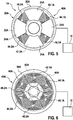
- the second exemplary embodiment of the coil arrangement 40A comprises three detection coils 42A, 44A, 46A which are arranged distributed over the circumference of the circular coil arrangement 40A and which each have two sub-coils 42.1A, 42.2A, 44.1A, 44.2A, 46.1A, 46.2A are divided. A total of six sub-coils 42.1A, 42.2A, 44.1A, 44.2A, 46.1A, 46.2A are thus distributed uniformly over the circumference of the circular coil arrangement 40A.
- the two partial coils 42.1A, 42.2A, 44.1A, 44.2A, 46.1A, 46.2A of the respective detection coils 42A, 44A, 46A are each distributed over the circumference of the circular coil arrangement 40A in such a way that lateral ones Positional tolerances can be compensated in the first approximation.
- the two partial coils 42.1A, 42.2A, 44.1A, 44.2A, 46.1A, 46.2A of the respective detection coils 42A, 44A, 46A are arranged opposite one another on the circumference of the circular coil arrangement 40A.
- the direction of winding of the two sub-coils 42.1A, 42.2A, 44.1A, 44.2A, 46.1A, 46.2A of the respective detection coil 42A, 44A, 46A is opposite, so that the magnetic field is very small at a distance from approximately three coil diameters and interferences can be compensated.
- the flat partial coils 42.1A, 42.2A, 44.1A, 44.2A, 46.1A, 46.2A are each designed as uniform circular ring segments with a predetermined opening angle of 50 °.
- a first detection coil 42A consists of the two flat partial coils 42.1A and 42.2A
- a second detection coil 44A consists of the two flat partial coils 44.1A and 44.2A
- a third detection coil 46A consists of the two flat partial coils 46.1A and 46.2 A.
- the target 20A of the illustrated second exemplary embodiment of the sensor arrangement 1A according to the invention for the contactless detection of rotation angles on a rotating component comprises four annular segment-shaped metal surfaces 24A with an opening angle of 60 °.
- Fig. 5 shows an example of the position of the targets 20A at an angle of rotation of 0 °, the definition being made by definition. It is obvious that a shift of the center of the target 20A in the positive y-direction (orientation corresponding to the sheet plane) increases the coverage of the second coil section 46.2A of the third detection coil 46A and decreases the coverage area of the first coil section 46.1A of the third Detection coil 46A leads.
- the relationship in this position of the target 20A does not apply to the partial coils 42.1A and 42.2A of the first detection coil 42A, since the larger design of the target 20A in the radial direction generally means that these partial coils 42.1A, 42.2A are not influenced by a small ( ⁇ 5% of the diameter) displacement of the target 20A in the y direction takes place.
- Lm represents the calculated mean value of the inductance of the partial coil, which results from the measured inductances of the partial coils 42.1A, 42.2A, 44.1A, 44.2A, 46.1A, 46.2A of the respective detection coil 42A, 44A, 46A and can be determined according to equation (4).
- L1 and L2 each represent the measured inductance of the corresponding sub-coils 42.1A, 42.2A, 44.1A, 44.2A, 46.1A, 46.2A.
- L m L 1 + L 2 2
- the calculation can take place in the evaluation and control unit 10.
- the two partial coils 42.1A, 42.2A, 44.1A, 44.2A, 46.1A, 46.2A of the detection coils 42A, 44A, 46A are electrically connected in series. Since the coupling factors between the sub-coils 42.1A, 42.2A, 44.1A, 44.2A, 46.1A, 46.2A are relatively small with k ⁇ 0.02, the inductances add up. The averaging is thus practically "analog" without computing effort. Furthermore, the number of connections between the coil arrangement 40A and the evaluation and control unit 10 is reduced.
- the partial coils 42.1A, 42.2A, 44.1A, 44.2A, 46.1A, 46.2A each wound in opposite directions. This reduces the magnetic field strength in the far field. If a homogeneous interference field is assumed, the same voltages, each with a different sign, are induced in both sub-coils 42.1A, 42.2A, 44.1A, 44.2A, 46.1A, 46.2A. Due to the series connection, both voltages ideally compensate to zero.
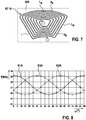
- Fig. 7 how from Fig. 7 can also be seen, have conductor tracks L with the thickness B, which form the respective winding of the partial coils 42.1A, 42.2A, 44.1A, 44.2A, 46.1A, 46.2A of the detection coils 42A, 44A, 46A, of which a first partial coil is an example 42.1A of the first detection coil 42A is shown, analogously to the first exemplary embodiment, circular-arc-shaped conductor track sections L B and radially extending conductor track sections L R.
- a distance d K which the arcuate conductor track sections L R have to one another, is preferably chosen to be as small as possible in order to have as many coil turns N as possible on the available area of the partial coil 42.1A, 42.2A, 44.1A, 44.2A, 46.1A, 46.2 A.
- the maximum number N of coil turns can be approximate can be calculated with equation (1).
- both the minimum conductor track width B and the minimum distance d K between two arcuate conductor track sections L B are, for example, 125 ⁇ m.
- the distance d R of the radially running conductor track sections L R is selected such that the radially running conductor track sections L R are as uniform as possible over the entire available area of the corresponding partial coil 42.1A, 42.2A, 44.1A, 44.2A, Distribute 46.1A, 46.2A.
- the appropriate track spacing d R can also be approximately calculated using equation (2).
- the distance d R is, for example, 230 ⁇ m.
- the evaluation and control unit 10 generating a first evaluation signal K1A by evaluating the first detection coil 42A with the sub-coils 42.1A and 42.2A, and a second Evaluation signal K2A generated by evaluating the second detection coil 44A with the partial coils 44.1A and 44.2A and a third evaluation signal K3A generated by evaluating the third detection coil 46A with the partial coils 46.1A and 46.2A. Furthermore, there is symmetry between the sub-coils 42.1A and 42.2A, 44.1A and 44.2A and 46.1A and 46.2A.
- the angle of rotation measurement range is 90 ° thanks to the use of four 24A metal surfaces.
- Analogous to the characteristic diagram according to Fig. 4 is in the in Fig. 8 A characteristic diagram shown along the vertical axis plots a resonance frequency which changes as a result of the change in inductance of the respective detection coil 42A, 44A, 46A.
- Other suitable measurable physical quantities can also be used to To detect and display the change in inductance of the respective detection coil 42A, 44A, 46A.
Landscapes
- Physics & Mathematics (AREA)
- General Physics & Mathematics (AREA)
- Transmission And Conversion Of Sensor Element Output (AREA)
- Measurement Of Length, Angles, Or The Like Using Electric Or Magnetic Means (AREA)
Claims (6)
- Arrangement détecteur destiné à détecter sans contact des angles de rotation sur un élément structural en rotation, l'élément structural en rotation étant couplé avec une cible (20) en forme de disque qui possède au moins deux surfaces métalliques (24) et qui, en association avec un arrangement de bobines (40) qui possède trois bobines de détection (42, 44, 46) plates, génère au moins une information destinée à la détermination de l'angle de rotation actuel de l'élément structural en rotation, les trois bobines de détection (42, 44, 46) plates étant distribuées uniformément sur le pourtour d'un cercle et les au moins deux surfaces métalliques (24), par des effets de courant de Foucault, influençant les inductances des bobines de détection (42, 44, 46) plates en fonction du degré de recouvrement, une unité d'interprétation et de commande (10) générant des signaux d'interprétation (K1, K2, K3) sensiblement sinusoïdaux qui représentent les variations d'inductance des bobines de détection (42, 44, 46) et les interprétant en vue de calculer l'angle de rotation, caractérisé en ce que les bobines de détection (42, 44, 46) plates sont respectivement réalisées sous la forme de segments de cercle et/ou de segments d'anneau circulaire de forme identique avec un angle d'ouverture prédéfini dans la plage de 100° à 120°.
- Arrangement détecteur destiné à détecter sans contact des angles de rotation sur un élément structural en rotation, l'élément structural en rotation étant couplé avec une cible (20A) en forme de disque qui possède au moins quatre surfaces métalliques (24A) et qui, en association avec un arrangement de bobines (40A) qui possède trois bobines de détection (42A, 44A, 46A) plates, génère au moins une information destinée à la détermination de l'angle de rotation actuel de l'élément structural en rotation, les trois bobines de détection (42A, 44A, 46A) plates étant distribuées uniformément sur le pourtour d'un cercle, les au moins quatre surfaces métalliques (24A), par des effets de courant de Foucault, influençant les inductances des bobines de détection (42A, 44A, 46A) plates en fonction du degré de recouvrement, une unité d'interprétation et de commande (10) générant des signaux d'interprétation (K1A, K2A, K3A) sensiblement sinusoïdaux qui représentent les variations d'inductance des bobines de détection (42A, 44A, 46A) et les interprétant en vue de calculer l'angle de rotation, les bobines de détection (42A, 44A, 46A) plates possédant respectivement deux bobines partielles (42.1A, 42.2A, 44.1A, 44.2A, 46.1A, 46.2A) qui sont disposées les unes en face des autres sur le pourtour du cercle, caractérisé en ce que les deux bobines partielles (42.1A, 42.2A, 44.1A, 44.2A, 46.1A, 46.2A) possèdent respectivement un sens d'enroulement opposé et sont réalisées sous la forme de segments de cercle et/ou de segments d'anneau circulaire de forme identique avec un angle d'ouverture prédéfini dans la plage de 50° à 60°.
- Arrangement détecteur selon l'une des revendications 1 et 2, caractérisé en ce qu'un écart (dK) entre deux portions de piste conductrice (LB) suivant un tracé en arc de cercle des bobines de détection (42, 44, 46) ou des bobines partielles (42.1A, 42.2A, 44.1A, 44.2A, 46.1A, 46.2A) individuelles est choisi le plus petit possible et un écart (dR) entre deux portions de piste conductrice (LR) suivant un tracé radial des bobines de détection (42, 44, 46) ou des bobines partielles (42.1A, 42.2A, 44.1A, 44.2A, 46.1A, 46.2A) individuelles est choisi de telle sorte que les portions de piste conductrice (LR) suivant un tracé radial se distribuent aussi régulièrement que possible sur la surface disponible des bobines de détection (42, 44, 46) ou des bobines partielles (42.1A, 42.2A, 44.1A, 44.2A, 46.1A, 46.2A) individuelles.
- Arrangement détecteur selon l'une des revendications 1 à 3, caractérisé en ce que les surfaces métalliques (24, 24A) sont respectivement réalisées sous la forme de segments de cercle et/ou de segments d'anneau circulaire de forme identique avec un angle d'ouverture prédéfini.
- Arrangement détecteur selon l'une des revendications 1, 3 et 4, caractérisé en ce que la cible (20) possède deux surfaces métalliques (24) disposées en face l'une de l'autre sur le pourtour d'un cercle, lesquelles possèdent respectivement un angle d'ouverture ayant une valeur dans la plage de 100° à 120°.
- Arrangement détecteur selon l'une des revendications 2 à 4, caractérisé en ce que la cible (20A) possède quatre surfaces métalliques (24A) distribuées uniformément sur le pourtour d'un cercle, lesquelles possèdent respectivement un angle d'ouverture ayant une valeur dans la plage de 50° à 60°.
Applications Claiming Priority (2)
| Application Number | Priority Date | Filing Date | Title |
|---|---|---|---|
| DE102014220454.2A DE102014220454A1 (de) | 2014-10-09 | 2014-10-09 | Sensoranordnung zur berührungslosen Erfassung von Drehwinkeln an einem rotierenden Bauteil |
| PCT/EP2015/072370 WO2016055301A1 (fr) | 2014-10-09 | 2015-09-29 | Ensemble capteur pour la détection sans contact d'angles de rotation sur un élément en rotation |
Publications (2)
| Publication Number | Publication Date |
|---|---|
| EP3204728A1 EP3204728A1 (fr) | 2017-08-16 |
| EP3204728B1 true EP3204728B1 (fr) | 2020-02-12 |
Family
ID=54293221
Family Applications (1)
| Application Number | Title | Priority Date | Filing Date |
|---|---|---|---|
| EP15778896.9A Active EP3204728B1 (fr) | 2014-10-09 | 2015-09-29 | Ensemble capteur pour la détection sans contact d'angles de rotation sur un élément en rotation |
Country Status (5)
| Country | Link |
|---|---|
| US (1) | US10330498B2 (fr) |
| EP (1) | EP3204728B1 (fr) |
| CN (1) | CN106796120B (fr) |
| DE (1) | DE102014220454A1 (fr) |
| WO (1) | WO2016055301A1 (fr) |
Families Citing this family (20)
| Publication number | Priority date | Publication date | Assignee | Title |
|---|---|---|---|---|
| DE102016206773A1 (de) * | 2016-04-21 | 2017-10-26 | Robert Bosch Gmbh | Motorsteuerelektronik für einen bürstenlosen Gleichstrommotor |
| DE102016217254B4 (de) | 2016-09-09 | 2022-02-17 | Robert Bosch Gmbh | Drehwinkelsensor, Statorelement sowie Rotorelement für diesen |
| DE102017211490A1 (de) * | 2017-07-06 | 2019-01-10 | Robert Bosch Gmbh | Drehwinkelsensoranordnung, LiDAR-System, Arbeitsvorrichtung und Betriebsverfahren für ein LiDAR-System |
| DE102017211491A1 (de) | 2017-07-06 | 2019-01-10 | Robert Bosch Gmbh | Drehwinkelsensoranordnung, LiDAR-System, Arbeitsvorrichtung und Betriebsverfahren für ein LiDar-System |
| DE102017211493A1 (de) | 2017-07-06 | 2019-01-10 | Robert Bosch Gmbh | Drehwinkelsensoranordnung, LiDAR-System und Arbeitsvorrichtung |
| EP3517896B1 (fr) * | 2018-01-30 | 2020-12-30 | Mecos AG | Capteur de position radiale sans contact ayant un comportement de réponse amélioré aux défauts de cible |
| CN112639406B (zh) * | 2018-09-14 | 2022-12-09 | Ksr Ip控股有限责任公司 | 用于感应位置传感器的耦合器元件形状 |
| DE102018221317A1 (de) * | 2018-12-10 | 2020-06-10 | Zf Friedrichshafen Ag | Induktive Drehwinkelerfassung |
| CN109506726A (zh) * | 2018-12-20 | 2019-03-22 | 江苏远传智能科技有限公司 | 感应式无磁远传水表 |
| CN111060164A (zh) * | 2019-12-26 | 2020-04-24 | 江苏远传智能科技有限公司 | 感应式旋转计量装置 |
| DE102020207225B4 (de) | 2020-06-09 | 2025-01-16 | Infineon Technologies Ag | Induktiver winkelsensor mit gestreckten spulen |
| CN114252766A (zh) * | 2020-09-22 | 2022-03-29 | 南京磁之汇电机有限公司 | 传感器及转角转速信号提取方法 |
| US11656100B2 (en) | 2020-10-08 | 2023-05-23 | Pulse Innovation Labs, Inc. | Angular displacement sensor |
| US11761794B2 (en) * | 2021-04-13 | 2023-09-19 | Hamilton Sundstrand Corporation | Proximity sensor to sense rotating shaft position and velocity |
| EP4367481A1 (fr) * | 2021-09-10 | 2024-05-15 | Bosch Car Multimedia Portugal, S.A. | Capteur de rotation |
| CN114720922B (zh) * | 2022-03-22 | 2025-03-11 | 泉州师范学院 | 磁敏传感单元阵列及平面二维磁场方向测量的方法 |
| DE102022205695A1 (de) * | 2022-06-03 | 2023-12-14 | Adaptive Balancing Power GmbH | Sensoreinrichtung zum berührungslosen Bestimmen einer radialen Position eines Rotors |
| JP7649931B1 (ja) * | 2024-07-12 | 2025-03-21 | マブチモーター株式会社 | レゾルバ |
| WO2026013909A1 (fr) * | 2024-07-12 | 2026-01-15 | マブチモーター株式会社 | Résolveur |
| CN118937473A (zh) * | 2024-07-24 | 2024-11-12 | 武汉盛势启创科技有限公司 | 应用于车用电机位置电涡流传感器的线圈组件 |
Family Cites Families (13)
| Publication number | Priority date | Publication date | Assignee | Title |
|---|---|---|---|---|
| DE9105145U1 (de) * | 1991-04-26 | 1992-08-27 | Papst-Motoren GmbH & Co KG, 7742 St Georgen | Positionssensor für Drehbewegungen |
| DE19738836A1 (de) | 1997-09-05 | 1999-03-11 | Hella Kg Hueck & Co | Induktiver Winkelsensor |
| WO2000079231A1 (fr) * | 1999-06-21 | 2000-12-28 | The Furukawa Electric Co., Ltd. | Détecteur rotatif et circuit de mesure de celui-ci |
| US6304076B1 (en) * | 1999-09-07 | 2001-10-16 | Bei Sensors & Systems Company, Inc. | Angular position sensor with inductive attenuating coupler |
| DE10104116A1 (de) * | 2001-01-31 | 2002-08-01 | Philips Corp Intellectual Pty | Anordnung zum Erfassen des Drehwinkels eines drehbaren Elements |
| FR2882818B1 (fr) * | 2005-03-07 | 2007-10-19 | Sappel Soc Par Actions Simplif | Capteur inductif de position angulaire |
| JP5147213B2 (ja) * | 2006-10-11 | 2013-02-20 | 日立オートモティブシステムズ株式会社 | インダクタンス式回転角度検出装置及びそれを備えたモータ駆動式の絞り弁制御装置 |
| DE102007015524A1 (de) * | 2007-03-30 | 2008-10-09 | Cherry Gmbh | Verfahren zum Herstellen eines induktiven Bedämpfungselements und induktives Wirbelstrombetätigungselement |
| DE102007037217B4 (de) | 2007-08-07 | 2023-11-16 | Robert Bosch Gmbh | Induktive Messeinrichtung zur berührungslosen Erfassung der relativen Drehposition zwischen zwei Körpern mit diametral angeordneten Spulen |
| JP5298061B2 (ja) * | 2010-04-08 | 2013-09-25 | 日立オートモティブシステムズ株式会社 | インダクタンス式回転角度検出装置およびその実装方法 |
| DE102011102796A1 (de) * | 2011-05-23 | 2012-11-29 | Trw Automotive Electronics & Components Gmbh | Positionssensor, Aktor-Sensor-Vorrichtung und Verfahren zur induktiven Erfassung einer Position |
| JP2012247323A (ja) * | 2011-05-30 | 2012-12-13 | Hitachi Automotive Systems Ltd | インダクタンス式回転角度検出装置及びそれを備えたモータ駆動式の絞り弁制御装置 |
| DE102014220446A1 (de) * | 2014-10-09 | 2016-04-14 | Robert Bosch Gmbh | Sensoranordnung zur berührungslosen Erfassung von Drehwinkeln an einem rotierenden Bauteil |
-
2014
- 2014-10-09 DE DE102014220454.2A patent/DE102014220454A1/de not_active Withdrawn
-
2015
- 2015-09-29 CN CN201580055068.2A patent/CN106796120B/zh not_active Expired - Fee Related
- 2015-09-29 EP EP15778896.9A patent/EP3204728B1/fr active Active
- 2015-09-29 US US15/517,344 patent/US10330498B2/en not_active Expired - Fee Related
- 2015-09-29 WO PCT/EP2015/072370 patent/WO2016055301A1/fr not_active Ceased
Non-Patent Citations (1)
| Title |
|---|
| None * |
Also Published As
| Publication number | Publication date |
|---|---|
| CN106796120A (zh) | 2017-05-31 |
| WO2016055301A1 (fr) | 2016-04-14 |
| DE102014220454A1 (de) | 2016-04-14 |
| US10330498B2 (en) | 2019-06-25 |
| US20170292857A1 (en) | 2017-10-12 |
| CN106796120B (zh) | 2019-09-24 |
| EP3204728A1 (fr) | 2017-08-16 |
Similar Documents
| Publication | Publication Date | Title |
|---|---|---|
| EP3204728B1 (fr) | Ensemble capteur pour la détection sans contact d'angles de rotation sur un élément en rotation | |
| EP3204727B1 (fr) | Capteur de mesure sans contact de l'angle de rotation d'un composant tournant | |
| EP3645977B1 (fr) | Système de détection pour déterminer au moins une propriété de rotation d'un élément en rotation | |
| EP3365634B1 (fr) | Capteur d'angle de rotation | |
| EP3420318B1 (fr) | Capteur d'angle de rotation | |
| EP3479071B1 (fr) | Capteur d'angle, élément statorique et élément rotorique pour ceci | |
| DE102016202867B3 (de) | Drehwinkelsensor | |
| DE102015220615A1 (de) | Drehwinkelsensor | |
| DE102013224098A1 (de) | Sensoranordnung zur Erfassung von Drehwinkeln an einem rotierenden Bauteil in einem Fahrzeug | |
| DE102015220617A1 (de) | Drehwinkelsensor | |
| DE102015114608A1 (de) | Außeraxiales Sensorsystem | |
| EP3601955B1 (fr) | Dispositif capteur d'angle à compensation des champs parasites et procédé de détermination d'angle à compensation des champs parasites | |
| DE3903359A1 (de) | Einrichtung zur bestimmung des lenkraddrehwinkels eines kraftfahrzeuges | |
| DE102017222676A1 (de) | Wegsensor | |
| DE102018213249A1 (de) | Sensorsystem zur Bestimmung mindestens einer Rotationseigenschaft eines rotierenden Elements | |
| DE102015220624A1 (de) | Drehwinkelsensor | |
| EP1324050A2 (fr) | Ensemble de détection du mouvement d'un codeur | |
| DE102014113374B4 (de) | Magnetpositionssensor und Erfassungsverfahren | |
| DE102015220631A1 (de) | Drehwinkelsensor | |
| DE10012202C2 (de) | Einrichtung zur Erfassung von Geschwindigkeit, Bewegungsrichtung und/oder Position eines zu bewegenden Geräteteils | |
| DE102013207621B4 (de) | Winkelmessung, insbesondere berührungslos, mit Einzelsensoren | |
| DE102015220645A1 (de) | Drehwinkelsensor | |
| WO2016045816A1 (fr) | Ensemble formant capteur pour mesurer un déplacement et/ou un angle | |
| DE102018200234A1 (de) | Sensorsystem zur Bestimmung mindestens einer Rotationseigenschaft eines rotierenden Elements | |
| DE102017222575A1 (de) | Sensorsystem zur Bestimmung mindestens einer Rotationseigenschaft eines rotierenden Elements |
Legal Events
| Date | Code | Title | Description |
|---|---|---|---|
| STAA | Information on the status of an ep patent application or granted ep patent |
Free format text: STATUS: THE INTERNATIONAL PUBLICATION HAS BEEN MADE |
|
| PUAI | Public reference made under article 153(3) epc to a published international application that has entered the european phase |
Free format text: ORIGINAL CODE: 0009012 |
|
| STAA | Information on the status of an ep patent application or granted ep patent |
Free format text: STATUS: REQUEST FOR EXAMINATION WAS MADE |
|
| 17P | Request for examination filed |
Effective date: 20170509 |
|
| AK | Designated contracting states |
Kind code of ref document: A1 Designated state(s): AL AT BE BG CH CY CZ DE DK EE ES FI FR GB GR HR HU IE IS IT LI LT LU LV MC MK MT NL NO PL PT RO RS SE SI SK SM TR |
|
| AX | Request for extension of the european patent |
Extension state: BA ME |
|
| DAV | Request for validation of the european patent (deleted) | ||
| DAX | Request for extension of the european patent (deleted) | ||
| STAA | Information on the status of an ep patent application or granted ep patent |
Free format text: STATUS: EXAMINATION IS IN PROGRESS |
|
| 17Q | First examination report despatched |
Effective date: 20181128 |
|
| GRAP | Despatch of communication of intention to grant a patent |
Free format text: ORIGINAL CODE: EPIDOSNIGR1 |
|
| STAA | Information on the status of an ep patent application or granted ep patent |
Free format text: STATUS: GRANT OF PATENT IS INTENDED |
|
| INTG | Intention to grant announced |
Effective date: 20190819 |
|
| RIN1 | Information on inventor provided before grant (corrected) |
Inventor name: LEIDICH, STEFAN Inventor name: AMELING, RALF |
|
| GRAS | Grant fee paid |
Free format text: ORIGINAL CODE: EPIDOSNIGR3 |
|
| GRAA | (expected) grant |
Free format text: ORIGINAL CODE: 0009210 |
|
| STAA | Information on the status of an ep patent application or granted ep patent |
Free format text: STATUS: THE PATENT HAS BEEN GRANTED |
|
| AK | Designated contracting states |
Kind code of ref document: B1 Designated state(s): AL AT BE BG CH CY CZ DE DK EE ES FI FR GB GR HR HU IE IS IT LI LT LU LV MC MK MT NL NO PL PT RO RS SE SI SK SM TR |
|
| REG | Reference to a national code |
Ref country code: GB Ref legal event code: FG4D Free format text: NOT ENGLISH |
|
| REG | Reference to a national code |
Ref country code: CH Ref legal event code: EP |
|
| REG | Reference to a national code |
Ref country code: AT Ref legal event code: REF Ref document number: 1232715 Country of ref document: AT Kind code of ref document: T Effective date: 20200215 |
|
| REG | Reference to a national code |
Ref country code: DE Ref legal event code: R096 Ref document number: 502015011720 Country of ref document: DE |
|
| REG | Reference to a national code |
Ref country code: IE Ref legal event code: FG4D Free format text: LANGUAGE OF EP DOCUMENT: GERMAN |
|
| RAP2 | Party data changed (patent owner data changed or rights of a patent transferred) |
Owner name: ROBERT BOSCH GMBH |
|
| PG25 | Lapsed in a contracting state [announced via postgrant information from national office to epo] |
Ref country code: FI Free format text: LAPSE BECAUSE OF FAILURE TO SUBMIT A TRANSLATION OF THE DESCRIPTION OR TO PAY THE FEE WITHIN THE PRESCRIBED TIME-LIMIT Effective date: 20200212 Ref country code: RS Free format text: LAPSE BECAUSE OF FAILURE TO SUBMIT A TRANSLATION OF THE DESCRIPTION OR TO PAY THE FEE WITHIN THE PRESCRIBED TIME-LIMIT Effective date: 20200212 Ref country code: NO Free format text: LAPSE BECAUSE OF FAILURE TO SUBMIT A TRANSLATION OF THE DESCRIPTION OR TO PAY THE FEE WITHIN THE PRESCRIBED TIME-LIMIT Effective date: 20200512 |
|
| REG | Reference to a national code |
Ref country code: LT Ref legal event code: MG4D |
|
| REG | Reference to a national code |
Ref country code: NL Ref legal event code: MP Effective date: 20200212 |
|
| PG25 | Lapsed in a contracting state [announced via postgrant information from national office to epo] |
Ref country code: IS Free format text: LAPSE BECAUSE OF FAILURE TO SUBMIT A TRANSLATION OF THE DESCRIPTION OR TO PAY THE FEE WITHIN THE PRESCRIBED TIME-LIMIT Effective date: 20200612 Ref country code: BG Free format text: LAPSE BECAUSE OF FAILURE TO SUBMIT A TRANSLATION OF THE DESCRIPTION OR TO PAY THE FEE WITHIN THE PRESCRIBED TIME-LIMIT Effective date: 20200512 Ref country code: HR Free format text: LAPSE BECAUSE OF FAILURE TO SUBMIT A TRANSLATION OF THE DESCRIPTION OR TO PAY THE FEE WITHIN THE PRESCRIBED TIME-LIMIT Effective date: 20200212 Ref country code: SE Free format text: LAPSE BECAUSE OF FAILURE TO SUBMIT A TRANSLATION OF THE DESCRIPTION OR TO PAY THE FEE WITHIN THE PRESCRIBED TIME-LIMIT Effective date: 20200212 Ref country code: LV Free format text: LAPSE BECAUSE OF FAILURE TO SUBMIT A TRANSLATION OF THE DESCRIPTION OR TO PAY THE FEE WITHIN THE PRESCRIBED TIME-LIMIT Effective date: 20200212 Ref country code: GR Free format text: LAPSE BECAUSE OF FAILURE TO SUBMIT A TRANSLATION OF THE DESCRIPTION OR TO PAY THE FEE WITHIN THE PRESCRIBED TIME-LIMIT Effective date: 20200513 |
|
| PG25 | Lapsed in a contracting state [announced via postgrant information from national office to epo] |
Ref country code: NL Free format text: LAPSE BECAUSE OF FAILURE TO SUBMIT A TRANSLATION OF THE DESCRIPTION OR TO PAY THE FEE WITHIN THE PRESCRIBED TIME-LIMIT Effective date: 20200212 |
|
| PG25 | Lapsed in a contracting state [announced via postgrant information from national office to epo] |
Ref country code: DK Free format text: LAPSE BECAUSE OF FAILURE TO SUBMIT A TRANSLATION OF THE DESCRIPTION OR TO PAY THE FEE WITHIN THE PRESCRIBED TIME-LIMIT Effective date: 20200212 Ref country code: PT Free format text: LAPSE BECAUSE OF FAILURE TO SUBMIT A TRANSLATION OF THE DESCRIPTION OR TO PAY THE FEE WITHIN THE PRESCRIBED TIME-LIMIT Effective date: 20200705 Ref country code: LT Free format text: LAPSE BECAUSE OF FAILURE TO SUBMIT A TRANSLATION OF THE DESCRIPTION OR TO PAY THE FEE WITHIN THE PRESCRIBED TIME-LIMIT Effective date: 20200212 Ref country code: EE Free format text: LAPSE BECAUSE OF FAILURE TO SUBMIT A TRANSLATION OF THE DESCRIPTION OR TO PAY THE FEE WITHIN THE PRESCRIBED TIME-LIMIT Effective date: 20200212 Ref country code: SM Free format text: LAPSE BECAUSE OF FAILURE TO SUBMIT A TRANSLATION OF THE DESCRIPTION OR TO PAY THE FEE WITHIN THE PRESCRIBED TIME-LIMIT Effective date: 20200212 Ref country code: SK Free format text: LAPSE BECAUSE OF FAILURE TO SUBMIT A TRANSLATION OF THE DESCRIPTION OR TO PAY THE FEE WITHIN THE PRESCRIBED TIME-LIMIT Effective date: 20200212 Ref country code: CZ Free format text: LAPSE BECAUSE OF FAILURE TO SUBMIT A TRANSLATION OF THE DESCRIPTION OR TO PAY THE FEE WITHIN THE PRESCRIBED TIME-LIMIT Effective date: 20200212 Ref country code: ES Free format text: LAPSE BECAUSE OF FAILURE TO SUBMIT A TRANSLATION OF THE DESCRIPTION OR TO PAY THE FEE WITHIN THE PRESCRIBED TIME-LIMIT Effective date: 20200212 Ref country code: RO Free format text: LAPSE BECAUSE OF FAILURE TO SUBMIT A TRANSLATION OF THE DESCRIPTION OR TO PAY THE FEE WITHIN THE PRESCRIBED TIME-LIMIT Effective date: 20200212 |
|
| REG | Reference to a national code |
Ref country code: DE Ref legal event code: R097 Ref document number: 502015011720 Country of ref document: DE |
|
| PLBE | No opposition filed within time limit |
Free format text: ORIGINAL CODE: 0009261 |
|
| STAA | Information on the status of an ep patent application or granted ep patent |
Free format text: STATUS: NO OPPOSITION FILED WITHIN TIME LIMIT |
|
| 26N | No opposition filed |
Effective date: 20201113 |
|
| PG25 | Lapsed in a contracting state [announced via postgrant information from national office to epo] |
Ref country code: IT Free format text: LAPSE BECAUSE OF FAILURE TO SUBMIT A TRANSLATION OF THE DESCRIPTION OR TO PAY THE FEE WITHIN THE PRESCRIBED TIME-LIMIT Effective date: 20200212 |
|
| PG25 | Lapsed in a contracting state [announced via postgrant information from national office to epo] |
Ref country code: PL Free format text: LAPSE BECAUSE OF FAILURE TO SUBMIT A TRANSLATION OF THE DESCRIPTION OR TO PAY THE FEE WITHIN THE PRESCRIBED TIME-LIMIT Effective date: 20200212 Ref country code: SI Free format text: LAPSE BECAUSE OF FAILURE TO SUBMIT A TRANSLATION OF THE DESCRIPTION OR TO PAY THE FEE WITHIN THE PRESCRIBED TIME-LIMIT Effective date: 20200212 |
|
| REG | Reference to a national code |
Ref country code: CH Ref legal event code: PL |
|
| GBPC | Gb: european patent ceased through non-payment of renewal fee |
Effective date: 20200929 |
|
| REG | Reference to a national code |
Ref country code: BE Ref legal event code: MM Effective date: 20200930 |
|
| PG25 | Lapsed in a contracting state [announced via postgrant information from national office to epo] |
Ref country code: LU Free format text: LAPSE BECAUSE OF NON-PAYMENT OF DUE FEES Effective date: 20200929 |
|
| PG25 | Lapsed in a contracting state [announced via postgrant information from national office to epo] |
Ref country code: LI Free format text: LAPSE BECAUSE OF NON-PAYMENT OF DUE FEES Effective date: 20200930 Ref country code: GB Free format text: LAPSE BECAUSE OF NON-PAYMENT OF DUE FEES Effective date: 20200929 Ref country code: IE Free format text: LAPSE BECAUSE OF NON-PAYMENT OF DUE FEES Effective date: 20200929 Ref country code: BE Free format text: LAPSE BECAUSE OF NON-PAYMENT OF DUE FEES Effective date: 20200930 Ref country code: CH Free format text: LAPSE BECAUSE OF NON-PAYMENT OF DUE FEES Effective date: 20200930 |
|
| PGFP | Annual fee paid to national office [announced via postgrant information from national office to epo] |
Ref country code: FR Payment date: 20210927 Year of fee payment: 7 |
|
| REG | Reference to a national code |
Ref country code: AT Ref legal event code: MM01 Ref document number: 1232715 Country of ref document: AT Kind code of ref document: T Effective date: 20200929 |
|
| PG25 | Lapsed in a contracting state [announced via postgrant information from national office to epo] |
Ref country code: AT Free format text: LAPSE BECAUSE OF NON-PAYMENT OF DUE FEES Effective date: 20200929 |
|
| PG25 | Lapsed in a contracting state [announced via postgrant information from national office to epo] |
Ref country code: TR Free format text: LAPSE BECAUSE OF FAILURE TO SUBMIT A TRANSLATION OF THE DESCRIPTION OR TO PAY THE FEE WITHIN THE PRESCRIBED TIME-LIMIT Effective date: 20200212 Ref country code: MT Free format text: LAPSE BECAUSE OF FAILURE TO SUBMIT A TRANSLATION OF THE DESCRIPTION OR TO PAY THE FEE WITHIN THE PRESCRIBED TIME-LIMIT Effective date: 20200212 Ref country code: CY Free format text: LAPSE BECAUSE OF FAILURE TO SUBMIT A TRANSLATION OF THE DESCRIPTION OR TO PAY THE FEE WITHIN THE PRESCRIBED TIME-LIMIT Effective date: 20200212 |
|
| PG25 | Lapsed in a contracting state [announced via postgrant information from national office to epo] |
Ref country code: MK Free format text: LAPSE BECAUSE OF FAILURE TO SUBMIT A TRANSLATION OF THE DESCRIPTION OR TO PAY THE FEE WITHIN THE PRESCRIBED TIME-LIMIT Effective date: 20200212 Ref country code: MC Free format text: LAPSE BECAUSE OF FAILURE TO SUBMIT A TRANSLATION OF THE DESCRIPTION OR TO PAY THE FEE WITHIN THE PRESCRIBED TIME-LIMIT Effective date: 20200212 Ref country code: AL Free format text: LAPSE BECAUSE OF FAILURE TO SUBMIT A TRANSLATION OF THE DESCRIPTION OR TO PAY THE FEE WITHIN THE PRESCRIBED TIME-LIMIT Effective date: 20200212 |
|
| PG25 | Lapsed in a contracting state [announced via postgrant information from national office to epo] |
Ref country code: FR Free format text: LAPSE BECAUSE OF NON-PAYMENT OF DUE FEES Effective date: 20220930 |
|
| PGFP | Annual fee paid to national office [announced via postgrant information from national office to epo] |
Ref country code: DE Payment date: 20251121 Year of fee payment: 11 |
|
| REG | Reference to a national code |
Ref country code: DE Ref legal event code: R084 Ref document number: 502015011720 Country of ref document: DE |