EP3204828B1 - Positionssensor für ein uhreinstellungssystem - Google Patents
Positionssensor für ein uhreinstellungssystem Download PDFInfo
- Publication number
- EP3204828B1 EP3204828B1 EP15777894.5A EP15777894A EP3204828B1 EP 3204828 B1 EP3204828 B1 EP 3204828B1 EP 15777894 A EP15777894 A EP 15777894A EP 3204828 B1 EP3204828 B1 EP 3204828B1
- Authority
- EP
- European Patent Office
- Prior art keywords
- capacitance
- rotatable element
- stator
- angular
- instantaneous
- Prior art date
- Legal status (The legal status is an assumption and is not a legal conclusion. Google has not performed a legal analysis and makes no representation as to the accuracy of the status listed.)
- Active
Links
Images




Classifications
-
- G—PHYSICS
- G01—MEASURING; TESTING
- G01D—MEASURING NOT SPECIALLY ADAPTED FOR A SPECIFIC VARIABLE; ARRANGEMENTS FOR MEASURING TWO OR MORE VARIABLES NOT COVERED IN A SINGLE OTHER SUBCLASS; TARIFF METERING APPARATUS; MEASURING OR TESTING NOT OTHERWISE PROVIDED FOR
- G01D5/00—Mechanical means for transferring the output of a sensing member; Means for converting the output of a sensing member to another variable where the form or nature of the sensing member does not constrain the means for converting; Transducers not specially adapted for a specific variable
- G01D5/12—Mechanical means for transferring the output of a sensing member; Means for converting the output of a sensing member to another variable where the form or nature of the sensing member does not constrain the means for converting; Transducers not specially adapted for a specific variable using electric or magnetic means
- G01D5/14—Mechanical means for transferring the output of a sensing member; Means for converting the output of a sensing member to another variable where the form or nature of the sensing member does not constrain the means for converting; Transducers not specially adapted for a specific variable using electric or magnetic means influencing the magnitude of a current or voltage
- G01D5/24—Mechanical means for transferring the output of a sensing member; Means for converting the output of a sensing member to another variable where the form or nature of the sensing member does not constrain the means for converting; Transducers not specially adapted for a specific variable using electric or magnetic means influencing the magnitude of a current or voltage by varying capacitance
- G01D5/241—Mechanical means for transferring the output of a sensing member; Means for converting the output of a sensing member to another variable where the form or nature of the sensing member does not constrain the means for converting; Transducers not specially adapted for a specific variable using electric or magnetic means influencing the magnitude of a current or voltage by varying capacitance by relative movement of capacitor electrodes
- G01D5/2412—Mechanical means for transferring the output of a sensing member; Means for converting the output of a sensing member to another variable where the form or nature of the sensing member does not constrain the means for converting; Transducers not specially adapted for a specific variable using electric or magnetic means influencing the magnitude of a current or voltage by varying capacitance by relative movement of capacitor electrodes by varying overlap
-
- G—PHYSICS
- G04—HOROLOGY
- G04C—ELECTROMECHANICAL CLOCKS OR WATCHES
- G04C3/00—Electromechanical clocks or watches independent of other time-pieces and in which the movement is maintained by electric means
- G04C3/001—Electromechanical switches for setting or display
- G04C3/007—Electromechanical contact-making and breaking devices acting as pulse generators for setting
-
- H—ELECTRICITY
- H03—ELECTRONIC CIRCUITRY
- H03K—PULSE TECHNIQUE
- H03K17/00—Electronic switching or gating, i.e. not by contact-making and –breaking
- H03K17/94—Electronic switching or gating, i.e. not by contact-making and –breaking characterised by the way in which the control signals are generated
- H03K17/965—Switches controlled by moving an element forming part of the switch
- H03K17/975—Switches controlled by moving an element forming part of the switch using a capacitive movable element
-
- H—ELECTRICITY
- H03—ELECTRONIC CIRCUITRY
- H03K—PULSE TECHNIQUE
- H03K2217/00—Indexing scheme related to electronic switching or gating, i.e. not by contact-making or -breaking covered by H03K17/00
- H03K2217/94—Indexing scheme related to electronic switching or gating, i.e. not by contact-making or -breaking covered by H03K17/00 characterised by the way in which the control signal is generated
- H03K2217/94057—Rotary switches
- H03K2217/94068—Rotary switches with magnetic detection
Definitions
- the present invention relates to the field of sensing position and/or motion of a rotatable setting stem of a timepiece. More specifically, but not exclusively, the present invention relates to a capacitive sensor arrangement suitable for sensing the motion and/or position of a timepiece setting stem.
- rotation/motion sensors must be able to detect tiny movements of a tiny object, for example the rotation of a setting stem having a diameter of one millimeter or even less.
- the sensor components must also themselves be small, since space is limited. Such sensors should preferably be contactless in order to reduce wear and thereby extend the serviceable life of the timepiece.
- the sensor components should also be easy to manufacture.
- a contactless sensor has been proposed in US patent US6252825 , which describes the use of a capacitive sensor for detecting positions and/or movements of a setting stem of a timepiece.
- the setting stem is provided with a rotor electrode which is shaped so as to modulate a capacitance between two stator electrodes.
- An embodiment is also described in which two such capacitances are arranged in quadrature in order to enable a sensor control system to deduce the direction of rotation of the setting stem.
- US 2013/0271119 discloses the detection of the angular position of an electrode rotor by sensing a coupling between two adjacent stator electrodes. This coupling is generated by a coupling electrode of the rotor.
- the instantaneous capacitance of a pair of electrodes depends on the angular positioning of the rotor.
- the proposed new solution enables a more precise measurement of the position and/or the motion of the rotatable element, hence providing a finer resolution, yet without requiring a higher number of rotor and/or stator electrodes of the sensor.
- the use of differential capacitance values in determining the angular position further improves the immunity of the capacitive sensor to external influences such as stray capacitances or variations due to changes in humidity or temperature, and thereby to its measurement accuracy.
- the rotor electrode is made of two identical parts stretching symmetrically along a diameter on either side around its rotation axis, so that the position is determined with a precision of +/- 180 degrees only. As a result, only an incremental sensor is provided for measuring an angular displacement or speed, but no absolute angular position.
- the first and second rotor electrodes and the first, second, third, fourth, fifth and sixth stator electrodes are configured such that the capacitances values of C 1 , C 2 , C 3 and C 4 can be sensed between the first and second, the second and third, the fourth and fifth and the fifth and sixth stator electrodes respectively.
- the first differential capacitance pair and the second differential capacitance pair are arranged such that X 1-2 varies as a first function of the rotational position of the rotatable element, and X 3-4 varies as a second function of the rotational position of the rotatable element.
- the first and/or second functions are substantially sinusoidal or cosinusoidal, with a period of 180°.
- the second function has the same form as the first function, but is phase-shifted with respect to the first function by a phase-shift angle in the rotation cycle.
- phase-shift angle is substantially 45 degrees, +/- 90 degrees, which allows to derive the rotational position of the rotatable element with the help of a trigonometric formula.
- the first, second and third, and/or the fourth, fifth and sixth stator electrodes are arranged in a common plane orthogonal to the rotation axis of the rotatable element. This allows simplifying the machining process and improving compactness of the provided sensor device.
- the first rotor electrode and/or the second rotor electrode is formed in an axial end face of the rotatable element.
- the first and second rotor electrodes are formed in a same plane as well, in order to simplify the machining.
- first, second and third, and/or fourth, fifth and sixth stator electrodes are arranged adjacent to a peripheral face of the rotatable element.
- the first rotor electrode and/or the second rotor electrode is formed in or on the peripheral face of the rotatable element.
- the capacitive sensor comprises a stator element comprising a plurality of angular stator electrode regions arranged about the rotation axis of the rotatable element, wherein the first differential capacitance pair is located in a first one of the angular stator electrode regions and the second differential capacitance pair is located in a second one of the angular stator electrode regions, angularly displaced from the first angular stator electrode region by the phase-shift angle.
- the capacitive sensor comprises a rotor element comprising a plurality of angular rotor electrode regions arranged about the rotation axis of the rotatable element, wherein the first rotor electrode comprises a first one of the angular rotor electrode regions, and the second rotor electrode comprises a second one of the angular rotor electrode regions, the first angular rotor electrode region spreading over a larger angular sector than the second angular rotor electrode regions.
- the rotatable element is assembled to the distal end of the setting stem of the timepiece.
- the invention also aims to provide a sensor calculation unit for a capacitive sensor as described above, the sensor calculation unit being configured to determine the instantaneous angular orientation of the rotatable element comprising two rotor electrodes by:
- the maximal rotational speed determines the maximal time between two measurements. If the initial value is chosen arbitrarily, the position is defined on a range of 180°, which is sufficient for most watch applications, where no absolute angular positioning is required, but only incremental detection. If an absolute position is required, another sensor with one pulse per 360° should preferably be added, or the structure of the rotor electrode pair should be modified in order to be able to discriminate each of them with respect to the other.
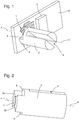
- Figure 1 shows an example of a rotatable element, such as a pinion shaft or a setting stem which may be found in a timepiece.
- a setting stem of a wristwatch will be taken as an illustrative example of an application of the capacitive sensor of the invention.
- a setting stem may also be known as a crown stem. Note that the setting stem itself is not illustrated in figure 1 .
- Rotatable element 3 is rotatable about a rotation axis 4 and is provided with an engagement means (in this example a slot 8) for engaging with a corresponding part of the setting stem.
- the engagement means in this example is designed to cooperate with the setting stem such that the setting stem can be moved axially along rotation axis 4 without causing any axial motion of the rotatable element 3, but such that any rotational motion of the setting stem is translated into a rotational motion of the rotatable element 3.
- the rotatable element 3 shown in figure 1 is provided at its distal end with one or more rotor electrodes 5.
- the rotor electrodes 5 are substantially planar and are arranged to face a number of stator electrodes which are similarly planar, in the same plane as the rotor electrodes, and separated from the rotor electrodes by a thin dielectric, which may be an air gap or a piece of solid dielectric material such as a plastic film, for example.
- the stator electrodes may advantageously be formed as tracks on a printed circuit board (PCB) 10, for example, and they are arranged to form two differential capacitance pairs indicated by arrows 1 and 2, for reasons which will be described later.
- the PCB 10 may also carry sensor driver circuitry 9 for providing an electrical interface to the differential capacitance pairs 1 and 2.
- the dimensions of the various elements shown in figure 1 would be tiny.
- the rotatable element 3 may be 1mm or less in diameter and the PCB 10 may have an area of five or six square millimetres or less.
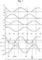
- Figure 2 shows a different view of the rotatable element 3 illustrated in figure 1 .
- This view shows the shape of the two electrodes 5a and 5b, which may be formed by milling two shoulders 6 into the peripheral surface at the distal end of the rotatable element 3.
- the end face of the rotatable element 3 may also comprise a spacer element 7 for providing a physical contact with, and thereby maintaining a constant spacing from, the PCB 10.
- Such a rotatable element 3, with the slot 8, the spacer element 7 and the shoulders 6 may be easily fabricated from metal, using standard machine-tool techniques, even when its dimensions are small.
- the spacer element 7 has a thickness that is typically comprised, for a rotatable element 3 meant for the setting stem of a wristwatch, within 0.05mm and 0.15mm, and allows to provide a greater shock robustness.
- FIG. 3 shows how the stator electrodes may be arranged to form, in capacitive proximity to the rotor electrodes two differential capacitance pairs 1 and 2.
- Six stator electrode regions 11, 12, 13, 21, 22 and 23 are illustrated in figure 3 (regions shaded with left-diagonal hatching) which in this example are each formed as part of a metal track of the PCB 10.
- Each of the metal tracks also comprises a connector pad 11', 12', 13', 21', 22', 23' (shaded with right-diagonal hatching) for connecting each of the respective stator electrodes 11, 12, 13, 21, 22 and 23 to sensor driver circuitry 9.
- stator electrodes 11, 12, 13, 21, 22 and 23 are formed as concentric arc segments centered on the axis of rotation 4 of the rotatable element 3, in order to allow a modeling of the capacitance values as a sine or cosine functions depending of the angular position of the rotatable element 3, on which are arranged rotor electrodes, as explained hereafter further in view of Figs 5-7 .
- This is simply one example of a configuration of the stator electrodes which can be used to carry out the invention.
- Other configurations are possible for the stator and rotor electrodes, that may be arranged around the periphery of the rotatable element 3 instead of (or as well as) orthogonal to the rotational axis 4, as in the illustrated example.
- Figures 8-11 show an alternative embodiment for the present invention with a rotatable element 3 split into two pieces, and stator electrodes arranged on a flexible substrate rolled around its periphery, as explained hereafter.
- the first differential capacitance pair 1 comprises first, second and third stator electrode regions 11, 12 and 13 (shaded with left-diagonal hatching), while the second differential capacitance pair 2 comprises fourth, fifth and sixth stator electrode regions 21, 22 and 23, similarly shaded.
- a rotor electrode is in close capacitive proximity facing two of the stator electrodes, for example the first and second stator electrodes 11 and 12, forming a first pair of stator electrodes, a capacitance is created between stator electrodes 11 and 12 via the rotor electrode.
- Figure 4 shows an example of a rotor electrode arrangement which is designed to face the stator electrodes depicted in figure 3 , and thereby create varying capacitances between pairs of the stator electrodes as the rotatable element 3 rotates.
- Rotor electrode regions 5a and 5b are shaded to indicate which regions of the axial end-face of rotational element 3 are brought into capacitive proximity with the stator electrodes 11, 12, 13, 21, 22 and 23, which respectively form a first pair of stator electrodes between the first 11 and second 12 stator electrodes, a second pair of stator electrodes between the second and third stator electrodes, a third pair of stator electrodes between the fourth 21 and fifth 22 stator electrode, and a fourth pair of stator electrodes between the fifth 22 and sixth 23 stator electrodes.
- These rotor electrode regions 5a and 5b are notional regions, and do not necessarily differ from the material of the surrounding rotatable element 3.
- the rotatable element 3 may be machined or otherwise fabricated from a single contiguous piece of metal or other conductive material, for example.
- the rotor electrodes 5a and 5b are preferably electrically connected to the ground potential that is the same as the metallic watchcase or movement plate.
- the rotor electrodes 5a and 5b play a passive role in the capacitances, such that the capacitances can be measured at the connections 11', 12', 13', 21', 22', 23' to the stator electrodes 11, 12, 13, 21, 22 and 23.
- Figures 5 and 6 show the same arrangements of stator and rotor electrodes as in figures 3 and 4 , but with angles and capacitances schematically indicated.
- X 1 represents the instantaneous value of the capacitance C 1 measurable between the first and second stator electrodes 11 and 12.
- X 1 has a maximum value (which will be referred to as zero for the sake of simplicity) when neither of the rotor electrodes 5a and 5b covers the first stator electrode 11 (i.e. no part of the angular sector ⁇ 5a or ⁇ 5b falls between ⁇ 7 and ⁇ 0 ), and a minimum value when either of the rotor electrodes 5a and 5b is fully covering the first stator electrode 11 (i.e.
- X 1 has an intermediate value when either of the rotor electrodes 5a or 5b is partially covering the first stator electrode 11 (i.e. when angular sector ⁇ 5a or ⁇ 5b partially coincides with angle between ⁇ 7 and ⁇ 0 ).
- the angular positions ⁇ 0 , ⁇ 1 , ⁇ 2 , ⁇ 3 , ⁇ 4 , ⁇ 5 , ⁇ 6 and ⁇ 7 each indicate a delimitation (i.e.
- angular sectors ⁇ 5a and ⁇ 5b of each of the rotor electrodes 5a and 5b may advantageously be arranged to extend angularly across two neighbouring segments delimited by the angular positions ⁇ 0 , ⁇ 1 , ⁇ 2 , ⁇ 3 , ⁇ 4 , ⁇ 5 , ⁇ 6 and ⁇ 7 , i.e. in this case around 90 degrees.
- each rotor electrode 5a and 5b creates a substantially uninterrupted variation of finite capacitance values X 1 , X 2 , X 3 and X 4 for each capacitance C 1 , C 2 , C 3 and C 4 as the respective rotor electrode 5a or 5b sweeps past the successive stator electrode pairs 11 and 12 (i.e. the first pair) 12 and 13 (i.e. the second pair); 21 and 22 (i.e. the third pair); and eventually 22 and 23, i.e. the fourth pair.
- Reference number 14 in figure 6 indicates a centreline that is in the middle of the two rotor electrodes 5a and 5b, which will be used as a reference when describing how the values of C1, C2, C3 and C4 vary during the rotation of the rotatable element 3.
- This centreline 14 is the one helping define the instantaneous angular position ⁇ R of the rotatable element 3.
- Figure 7 illustrates how each of the capacitance values X 1 , X 2 , X 3 and X 4 may vary with angular position ⁇ of the rotatable element 3 during such a clockwise rotation as the centreline 14 of the rotatable element 3 sweeps past angular positions ⁇ 0 , ⁇ 1 , ⁇ 2 , ⁇ 3 , ⁇ 4 , ⁇ 5 , ⁇ 6 and ⁇ 7 in succession.
- Figure 7 also shows how difference values X 1 -X 2 and X 3 -X 4 vary during the same clockwise rotation of the rotatable element 3 through angular positions ⁇ 0 , ⁇ 1 , ⁇ 2 , ⁇ 3 , ⁇ 4 , ⁇ 5 , ⁇ 6 and ⁇ 7 .
- Figure 7 also illustrates an example of how the angular position of the rotatable element 3 may be deduced from the instantaneous difference values X 1 -X 2 between capacitances C 1 and C 2 and X 3 -X 4 between capacitances C 3 and C 4 .
- the instantaneous measured values of X 1 -X 2 and X 3 -X 4 are x 1-2 and x 3-4 respectively.
- the quantity X 1 -X 2 varies with angular position ⁇ according to a first function
- the quantity X 3 -X 4 varies with angular position ⁇ according to a second function.
- the stator and rotor electrodes may be arranged such that the second function is similar to the first function, but phase-shifted by a predetermined phase-shift angle.
- the phase-shift angle is selected to be substantially 135 degrees, as it can be observed when comparing the values of X 1 -X 2 with the ones of X 3 -X 4 on Figure 7 .
- the stator and rotor electrodes may be arranged such that the first and second functions can be approximated to sine or cosine functions, as according to the preferred embodiment illustrated on figures 1-6 .
- angular resolution of the sensor is in any case far better than the one of each angular sector (i.e. 45 degrees) of the stator electrode.
- the value of the angular position ⁇ may be related to the values X 1-2 and X 3-4 by a look-up table of correspondence data or other source of correspondence information, as explained hereafter further in view of the bottom of figure 7 .
- the form of the first and second functions more generally depends on the shape of the rotor electrode (e.g. angular sector values ⁇ 5a or ⁇ 5b ) and on the size of stator electrode (e.g. when considering ⁇ 0 and ⁇ 7 as border angular positions and also depending its radius).
- a first instantaneous angular position ⁇ R can be arbitrarily chosen between the two possible values of the actual angular position pair ⁇ E and ⁇ F . Yet once this first angular position has been set, the instantaneous angular position ⁇ R will be preferably recursively defined by choosing, between the two possible angular values of angular position pair ⁇ E and ⁇ F , the one of the two values that is the closest to the last calculated instantaneous angular position ⁇ R . This corresponds, from both an empirical and statistical point of view, to the likeliest position in view of the last measured one. On figure 7 , this sought angle position turns out to correspond to ⁇ F .
- the angular displacement can then easily be calculated by computing the difference between the instantaneous angular position ⁇ R and the last calculated instantaneous angular position, which yields an angle comprised within -90° and 90°, as long as the angular speed remains under an upper limit set by the system. This limit can depend, among others, on the frequency of the measurements. The direction of the rotation is then simply indicated by the sign of this differential angle.
- the maximal allowed rotational speed determines the maximal time between two measurements.
- This measurement rate is directly proportional to the number of rotor electrodes. With an ideal absolute sensor, the measurement rate can be half of the value of the presented variant with 2 rotor electrodes.
- the goal is to measure an angular displacement that could be several rounds (>> 360°) during a time interval. The rotation speed and direction can be easily calculated from the angular displacement.
- the number of rotor electrodes, such as teeth should be much higher than two, as in the frame of the presented solution, in order to have the same resolution. Because of the small available volume, it isn't possible to realize such small teeth. As a result, the incremental sensor provided allows solving this technical problem in significantly increasing the angular resolution, without simultaneously requiring an increase of the number of rotor electrodes.
- the preferred calculation method described above is merely one the possible methods which may be used to deduce the actual angular position from measured values of the capacitances.
- the calculation may be carried out by suitable circuitry and/or software in sensor driver circuitry 9 on the PCB 10, or by a separate processor unit.
- the example configuration described above, comprising two rotor electrodes and two differential capacitance pairs, is also merely one of the possible configurations for carrying out the invention. Other numbers of rotor and/or static electrodes, and/or other relative angles between the electrodes may be used.
- FIGS. 8-11 described hereafter show an alternative embodiment for the present invention in which the stator electrodes are not arranged on the very same plane of a PCB 10 anymore, but on a flexible substrate 100 wrapped around the rotatable element 3, that is here shown mounted at the extremity of a timepiece stem 30.
- the rotatable element 3 is itself split into two distinct sub-pieces, i.e. a first sub-rotor 31 and a second sub-rotor 32 which are spaced apart by a slit 80 in which a fixed element (not shown) can be lodged in order to allow for a precise axial positioning along the rotation axis 4.
- stator electrodes are arranged according to an array pattern in which shows:
- the first sub-rotor 31 is disposed so as to fill in the gap between the first lateral row L of stator electrodes and the central row R of electrodes
- the second sub-rotor 32 is disposed so as to fill in the gap between the second lateral row L' of stator electrodes and the central electrodes R.
- the capacitance values between the first electrode of the first lateral row L1 and the first central electrode R1, forming a first pair of stator electrodes are modified depending on the angular position of the first sub-rotor 31 over its rotation cycle
- the capacitance values between the first electrode of the second lateral row L1' and the first central electrode R1, forming another first pair of stator electrodes are modified depending on the angular position of the second sub-rotor 32 over its rotation cycle.
- first differential capacitance pair 1 formed by the first and second capacitance C1 and C2, as well as a second differential capacitance pair 2, formed by the third and fourth capacitance, respectively, allows to derive the angular position of the rotatable element 3.
- second differential capacitance pair 2 formed by the third and fourth capacitance, respectively.
- the geometric shape of the rotatable element 3, determining the wave form of the output signals of the capacitance values, is preferably chosen to cover approximately two adjacent angular sectors - here corresponding to the stator electrodes of capacitances C2, C4 spreading over 45 degrees each and leave the two others - here capacitances C1, C3 - uncovered.
- an elliptic shape could also be considered without too much prejudice to the sinusoidal modeling of the capacitance values. Calculation based on look-up of correspondence data in tables will in any case still be available, and therefore choosing a shape easy to manufacture such as the one of Figure 10 could be privileged for mass production purposes.
Landscapes
- Physics & Mathematics (AREA)
- General Physics & Mathematics (AREA)
- Engineering & Computer Science (AREA)
- Power Engineering (AREA)
- Measurement Of Length, Angles, Or The Like Using Electric Or Magnetic Means (AREA)
- Transmission And Conversion Of Sensor Element Output (AREA)
- Electromechanical Clocks (AREA)
- Electric Clocks (AREA)
Claims (12)
- Kapazitiver Sensor zum Bestimmen einer momentanen Winkelposition (αR) eines drehbaren Elements (3) einer Uhr, wobei der kapazitive Sensor umfasst:- sechs Statorelektroden (11, 12, 13, 21, 22, 23), die als konzentrische Bogensegmente ausgebildet sind, die auf die Drehachse des drehbaren Elements zentriert sind, wobei sich die erste (11), dritte (13), vierte (21) und sechste (23) Statorelektrode entlang 45° erstrecken, und sich die zweite (12) und fünfte (22) Statorelektrode entlang 135° erstrecken, wobei sich die erste (11) und zweite (12) bzw. die zweite (12) und dritte (13), die vierte (21) und fünfte (22), und die fünfte (22) und sechste (23) Statorelektrode entlang eines gemeinsamen 45-Grad-winkligen Abschnitt erstrecken, wobei die 45-Grad-winkligen Abschnitte unterschiedlich sind,- eine Rotorelektrode (5a, 5b), die zum Drehen mit dem drehbaren Element (3) angeordnet ist, wobei die Rotorelektrode aus zwei identischen Teilen (5a, 5b) hergestellt ist, die sich symmetrisch auf beiden Seiten der Drehachse entlang 90° erstrecken,wobei die Rotorelektrode (5a, 5b) und die Statorelektroden (11, 12, 13, 21, 22, 23) so angeordnet sind, dass sie während eines Rotationszyklus des drehbaren Elements (3) Kapazitäten (C1, C2, C3, C4) zwischen zwei der sechs Statorelektroden (11, 12, 13, 21, 22, 23) bereitstellen, so dass jede der Kapazitäten (C1, C2, C3, C4) über mindestens einen Abschnitt des Rotationszyklus aufgrund des Einflusses der Rotorelektrode (5a,5b) variiert,
die Kapazitäten (C1, C2, C3, C4) ein erstes differentielles Kapazitätspaar (1) umfassen, das eine erste Kapazität (C1), die zwischen der ersten (11) und zweiten (12) Statorelektrode ausgebildet ist, und eine zweite Kapazität (C2), die zwischen der zweiten (12) und dritten (13) Statorelektrode ausgebildet ist, umfasst, wobei die erste Kapazität (C1) einen momentanen ersten Kapazitätswert X1 und die zweite Kapazität (C2) einen momentanen zweiten Kapazitätswerts X2 abhängig von der Winkelpositionierung der Rotorelektrode (5a,5b) aufweist;
die Kapazitäten (C1, C2, C3, C4) ein zweites differentielles Kapazitätspaar (2) umfassen, das eine dritte Kapazität (C3), die zwischen der vierten (21) und fünften (22) Statorelektrode ausgebildet ist, und eine vierte Kapazität (C4), die zwischen der fünften (22) und sechsten (23) Statorelektrode ausgebildet ist, umfasst, wobei die dritte Kapazität (C3) einen momentanen dritten Kapazitätswert X3 und die vierte Kapazität (C4) einen momentanen vierten Kapazitätswert X4 abhängig von der Winkelpositionierung der Rotorelektrode (5a,5b) aufweist, und
der kapazitive Sensor eine Sensortreiberschaltung (9) zum Erfassen von Kapazitätswerten X1, X2, X3 und X4 und zum Bestimmen der momentanen Winkelposition (αR) durch Auswerten eines ersten differentiellen Kapazitätswerts X1-2 = X1 - X2 und eines zweiten differentiellen Kapazitätswerts X3-4 = X3 - X4 umfasst. - Kapazitiver Sensor nach Anspruch 1, bei dem das erste differentielle Kapazitätspaar (1) und das zweite differentielle Kapazitätspaar (2) so angeordnet sind, dass der erste differentielle Kapazitätswert X1-2 als eine erste Funktion der momentanen Winkelposition (αR) des drehbaren Elements (3) variiert und der zweite differentielle Kapazitätswert X3-4 als eine zweite Funktion der momentanen Winkelposition (αR) des drehbaren Elements (3) variiert.
- Kapazitiver Sensor nach Anspruch 2, bei dem die erste und/oder zweite Funktion im Wesentlichen sinus- oder cosinusförmig mit einer Periode von 180° ist.
- Kapazitiver Sensor nach Anspruch 2 oder Anspruch 3, bei dem die zweite Funktion im Wesentlichen die gleiche Form wie die erste Funktion aufweist und mit Bezug auf die erste Funktion um einen Phasenverschiebungswinkel (α0 bis α3) im Rotationszyklus phasenverschoben ist.
- Kapazitiver Sensor nach Anspruch 4, bei dem der Phasenverschiebungswinkel im Wesentlichen 135 Grad oder 45 Grad beträgt.
- Kapazitiver Sensor nach einem der vorangehenden Ansprüche, wobei die erste (11), zweite (12) und dritte (13) und/oder die vierte (21), fünfte (22) und sechste (23) Statorelektrode in einer gemeinsamen Ebene orthogonal zu der Drehachse (4) des drehbaren Elements (3) angeordnet sind.
- Kapazitiver Sensor nach einem der vorangehenden Ansprüche, wobei der erste Rotorelektrodenteil (5a) und/oder der zweite Rotorelektrodenteil (5b) in einer axialen Endfläche des drehbaren Elements (3) ausgebildet ist.
- Kapazitiver Sensor nach einem der vorangehenden Ansprüche, wobei die erste (11), zweite (12) und dritte (13) und/oder vierte (21), fünfte (22) und sechste (23) Statorelektrode benachbart zu einer Umfangsfläche des drehbaren Elements (3) angeordnet sind.
- Kapazitiver Sensor nach Anspruch 8, wobei der erste Rotorelektrodenteil (5a) und/oder der zweite Rotorelektrodenteil (5b) in oder auf der Umfangsfläche des drehbaren Elements (3) ausgebildet ist.
- Kapazitiver Sensor nach einem der Ansprüche 4 bis 9, umfassend ein Statorelement (10) mit mehreren winkligen Statorelektrodenbereichen (α7 bis α2; α2 bis α5), die um die Drehachse (4) des drehbaren Elements (3) angeordnet sind, wobei das erste differentielle Kapazitätspaar (1) in einem ersten der winkligen Statorelektrodenbereiche (α7 bis α2) angeordnet ist und das zweite differentielle Kapazitätspaar (2) in einer zweiten der winkligen Statorelektrodenbereiche (α2 bis α5) angeordnet ist, der winkelmäßig von dem ersten winkligen Statorelektrodenbereich um den Phasenverschiebungswinkel verschoben ist.
- Kapazitiver Sensor nach einem der vorangehenden Ansprüche, wobei das drehbare Element (3) so angeordnet ist, dass es an einer Stellwelle der Uhr montierbar ist.
- Sensorberechnungseinheit (9) für einen kapazitiven Sensor nach einem der Ansprüche 2 bis 11, wobei die Sensorberechnungseinheit (9) konfiguriert ist, um die momentane Winkelposition (αR) des drehbaren Elements (3) zu bestimmen, durch:Bestimmen eines ersten differentiellen momentanen Werts (X1-2) eines ersten differentiellen Kapazitätswerts X1-2 = X1 - X2 zwischen der ersten Kapazität (C1) und der zweiten Kapazität (C2) und eines zweiten differentiellen momentanen Werts (x3-4) eines zweiten differentiellen Kapazitätswerts X3-4 = X3 - X4 zwischen der dritten Kapazität (C3) und der vierten Kapazität (C4);Verwenden vorbestimmter Korrespondenzinformationen der ersten Funktion, Identifizieren einer ersten Mehrzahl von plausiblen Werten (αA, αB, αC, αD) der ersten Funktion, die dem ersten differentiellen momentanen Wert (X1-2) entsprechen;Verwenden vorbestimmter Korrespondenzinformation der zweiten Funktion, Identifizieren einer zweiten Mehrzahl von plausiblen Werten (αE, αF) der zweiten Funktion, die dem zweiten momentanen Wert (x3-4) entsprechen; wobei die zweite Mehrzahl von plausiblen Werten (αE, αF) ein Paar von Winkelwerten ist, die um 180° abhängig von der Winkelposition der zwei Rotorelektroden (5a, 5b) getrennt sind, undAuswählen eines Winkelwerts unter diesem Paar der zweiten Mehrzahl von plausiblen Werten (αE, αF), der der letzten zuvor berechneten Winkelposition am nächsten liegt, als die momentane Winkelposition (αR).
Applications Claiming Priority (2)
| Application Number | Priority Date | Filing Date | Title |
|---|---|---|---|
| EP14187867.8A EP3007013A1 (de) | 2014-10-07 | 2014-10-07 | Positionssensor für einen Uhreneinstellschaft |
| PCT/EP2015/071907 WO2016055275A2 (en) | 2014-10-07 | 2015-09-23 | Position sensor for a timepiece setting stem |
Publications (2)
| Publication Number | Publication Date |
|---|---|
| EP3204828A2 EP3204828A2 (de) | 2017-08-16 |
| EP3204828B1 true EP3204828B1 (de) | 2020-01-15 |
Family
ID=51660370
Family Applications (2)
| Application Number | Title | Priority Date | Filing Date |
|---|---|---|---|
| EP14187867.8A Withdrawn EP3007013A1 (de) | 2014-10-07 | 2014-10-07 | Positionssensor für einen Uhreneinstellschaft |
| EP15777894.5A Active EP3204828B1 (de) | 2014-10-07 | 2015-09-23 | Positionssensor für ein uhreinstellungssystem |
Family Applications Before (1)
| Application Number | Title | Priority Date | Filing Date |
|---|---|---|---|
| EP14187867.8A Withdrawn EP3007013A1 (de) | 2014-10-07 | 2014-10-07 | Positionssensor für einen Uhreneinstellschaft |
Country Status (5)
| Country | Link |
|---|---|
| US (1) | US10041813B2 (de) |
| EP (2) | EP3007013A1 (de) |
| JP (1) | JP6310615B2 (de) |
| CN (1) | CN106796121B (de) |
| WO (1) | WO2016055275A2 (de) |
Families Citing this family (31)
| Publication number | Priority date | Publication date | Assignee | Title |
|---|---|---|---|---|
| US9753436B2 (en) | 2013-06-11 | 2017-09-05 | Apple Inc. | Rotary input mechanism for an electronic device |
| CN109634447B (zh) | 2013-08-09 | 2022-04-19 | 苹果公司 | 用于电子设备的触觉开关 |
| WO2015122885A1 (en) | 2014-02-12 | 2015-08-20 | Bodhi Technology Ventures Llc | Rejection of false turns of rotary inputs for electronic devices |
| US10599101B2 (en) | 2014-09-02 | 2020-03-24 | Apple Inc. | Wearable electronic device |
| KR101940943B1 (ko) | 2015-03-05 | 2019-01-21 | 애플 인크. | 방향 종속 광학 특성을 갖는 광학 인코더 |
| WO2016144919A1 (en) | 2015-03-08 | 2016-09-15 | Apple Inc. | Compressible seal for rotatable and translatable input mechanisms |
| US10018966B2 (en) | 2015-04-24 | 2018-07-10 | Apple Inc. | Cover member for an input mechanism of an electronic device |
| US9891651B2 (en) | 2016-02-27 | 2018-02-13 | Apple Inc. | Rotatable input mechanism having adjustable output |
| US10551798B1 (en) | 2016-05-17 | 2020-02-04 | Apple Inc. | Rotatable crown for an electronic device |
| US10061399B2 (en) | 2016-07-15 | 2018-08-28 | Apple Inc. | Capacitive gap sensor ring for an input device |
| US10019097B2 (en) | 2016-07-25 | 2018-07-10 | Apple Inc. | Force-detecting input structure |
| US10664074B2 (en) | 2017-06-19 | 2020-05-26 | Apple Inc. | Contact-sensitive crown for an electronic watch |
| US10962935B1 (en) | 2017-07-18 | 2021-03-30 | Apple Inc. | Tri-axis force sensor |
| EP3438765B1 (de) | 2017-08-04 | 2020-02-05 | ETA SA Manufacture Horlogère Suisse | Uhrwerk, das eine vorrichtung zur erfassung der winkelposition eines rads umfasst |
| US11360440B2 (en) | 2018-06-25 | 2022-06-14 | Apple Inc. | Crown for an electronic watch |
| US11561515B2 (en) | 2018-08-02 | 2023-01-24 | Apple Inc. | Crown for an electronic watch |
| US12259690B2 (en) | 2018-08-24 | 2025-03-25 | Apple Inc. | Watch crown having a conductive surface |
| CN209560398U (zh) | 2018-08-24 | 2019-10-29 | 苹果公司 | 电子表 |
| US11181863B2 (en) | 2018-08-24 | 2021-11-23 | Apple Inc. | Conductive cap for watch crown |
| US11194298B2 (en) | 2018-08-30 | 2021-12-07 | Apple Inc. | Crown assembly for an electronic watch |
| CN209625187U (zh) | 2018-08-30 | 2019-11-12 | 苹果公司 | 电子手表和电子设备 |
| JP7110886B2 (ja) | 2018-10-02 | 2022-08-02 | カシオ計算機株式会社 | 回転検出装置及び電子時計 |
| US11194299B1 (en) | 2019-02-12 | 2021-12-07 | Apple Inc. | Variable frictional feedback device for a digital crown of an electronic watch |
| US11016535B1 (en) * | 2020-01-21 | 2021-05-25 | Pixart Imaging Inc. | Electronic device capable of detecting wearing state or touching state |
| EP3893063B1 (de) * | 2020-04-06 | 2022-08-17 | ETA SA Manufacture Horlogère Suisse | Kontrollvorrichtung der funktionen einer armbanduhr |
| US11550268B2 (en) | 2020-06-02 | 2023-01-10 | Apple Inc. | Switch module for electronic crown assembly |
| CN113010052A (zh) * | 2021-03-16 | 2021-06-22 | 维沃移动通信有限公司 | 智能手表、交互方法及交互装置 |
| US12092996B2 (en) | 2021-07-16 | 2024-09-17 | Apple Inc. | Laser-based rotation sensor for a crown of an electronic watch |
| US12189347B2 (en) | 2022-06-14 | 2025-01-07 | Apple Inc. | Rotation sensor for a crown of an electronic watch |
| CN115808866A (zh) * | 2022-12-09 | 2023-03-17 | 杭州精诚三和定时器实业有限公司 | 一种具有闹钟功能的计时器 |
| CN115755562A (zh) * | 2022-12-09 | 2023-03-07 | 杭州精诚三和定时器实业有限公司 | 一种采用角度位移传感器设定闹响时间的闹钟 |
Family Cites Families (14)
| Publication number | Priority date | Publication date | Assignee | Title |
|---|---|---|---|---|
| CN87207399U (zh) * | 1987-08-14 | 1988-04-20 | 上海量具刃具厂 | 电容式角位移传感器 |
| CN1044853A (zh) * | 1990-02-19 | 1990-08-22 | 许建平 | 电容式定向倾斜检测角位移传感器 |
| FR2759792B1 (fr) | 1997-02-17 | 1999-04-16 | Centre Electron Horloger | Piece d'horlogerie comportant un dispositif de detection sans contact |
| JP2967413B1 (ja) * | 1998-04-20 | 1999-10-25 | 株式会社千葉精密 | 回転差動容量型角度変換器 |
| JP3396454B2 (ja) * | 1999-12-28 | 2003-04-14 | 株式会社千葉精密 | 可動磁石形検流計 |
| DE10133216B4 (de) * | 2001-07-09 | 2005-01-27 | Tecpharma Licensing Ag | Positionsdetektion |
| JP2004061355A (ja) * | 2002-07-30 | 2004-02-26 | Alps Electric Co Ltd | 回転検出装置 |
| FR2882818B1 (fr) * | 2005-03-07 | 2007-10-19 | Sappel Soc Par Actions Simplif | Capteur inductif de position angulaire |
| ITTO20080604A1 (it) * | 2008-07-31 | 2010-02-01 | St Microelectronics Srl | Micromotore elettrostatico con statore e rotore a contatto, in particolare per sistemi di memorizzazione probe storage |
| DE102009043977A1 (de) * | 2008-12-12 | 2010-06-17 | Fanuc Ltd. | Kapazitiver Codierer |
| DE202010011758U1 (de) * | 2010-08-25 | 2010-11-25 | Abb Technology Ag | Sensoranordnung zur kontaktlosen Ermittlung der aktuellen Winkelstellung einer Welle |
| DE102010046778B4 (de) * | 2010-09-28 | 2017-11-02 | Trw Automotive Electronics & Components Gmbh | Kapazitiver Drehgeber |
| DE102011102796A1 (de) * | 2011-05-23 | 2012-11-29 | Trw Automotive Electronics & Components Gmbh | Positionssensor, Aktor-Sensor-Vorrichtung und Verfahren zur induktiven Erfassung einer Position |
| US8508270B2 (en) * | 2011-07-28 | 2013-08-13 | Intel Corporation | System and method for adjusting a characteristic of a periodic signal with use of a filtered bias voltage |
-
2014
- 2014-10-07 EP EP14187867.8A patent/EP3007013A1/de not_active Withdrawn
-
2015
- 2015-09-23 EP EP15777894.5A patent/EP3204828B1/de active Active
- 2015-09-23 JP JP2017518085A patent/JP6310615B2/ja active Active
- 2015-09-23 US US15/516,752 patent/US10041813B2/en active Active
- 2015-09-23 WO PCT/EP2015/071907 patent/WO2016055275A2/en not_active Ceased
- 2015-09-23 CN CN201580054191.2A patent/CN106796121B/zh active Active
Non-Patent Citations (1)
| Title |
|---|
| None * |
Also Published As
| Publication number | Publication date |
|---|---|
| CN106796121A (zh) | 2017-05-31 |
| US20170307414A1 (en) | 2017-10-26 |
| WO2016055275A3 (en) | 2016-06-30 |
| EP3007013A1 (de) | 2016-04-13 |
| CN106796121B (zh) | 2019-10-15 |
| JP2017531798A (ja) | 2017-10-26 |
| WO2016055275A2 (en) | 2016-04-14 |
| US10041813B2 (en) | 2018-08-07 |
| EP3204828A2 (de) | 2017-08-16 |
| JP6310615B2 (ja) | 2018-04-11 |
Similar Documents
| Publication | Publication Date | Title |
|---|---|---|
| US10041813B2 (en) | Position sensor for a timepiece setting stem | |
| US6252825B1 (en) | Timepiece comprising a capacitive sensing device | |
| US8847611B2 (en) | Capacitive differential quadrature rotary position sensor | |
| CN1846123B (zh) | 测量扭矩的方法和系统 | |
| JP2020003486A (ja) | 電磁誘導式エンコーダにおける受信線間隔 | |
| CN205506077U (zh) | 机电装置 | |
| US20150253153A1 (en) | Variable Reluctance Resolve-Encoder | |
| JP6507347B2 (ja) | 静電容量式角度検出装置 | |
| CN103124896A (zh) | 电容式的旋转编码器 | |
| JP6378431B2 (ja) | 計時器用セッティングステムの位置を判断する位置センサー及び方法 | |
| US20080066335A1 (en) | Position indicator, measuring apparatus and method of manufacturing a position indicator | |
| HK1237863A1 (en) | Position sensor for a timepiece setting stem | |
| HK1237863B (zh) | 用於时计设定杆的位置传感器 | |
| JPH0358447B2 (de) | ||
| EP3098571B1 (de) | Nichtflüchtiger rotationssensor mit magnetischen partikeln in serpentinenspur | |
| EP4414664A1 (de) | Rotierende kodiervorrichtung | |
| JP2001012968A (ja) | ロータリーエンコーダー | |
| JP2006047135A (ja) | 静電エンコーダ | |
| KR20120034946A (ko) | 회전형 토크 측정장치에 구비되는 알피엠 측정장치 | |
| RU145001U1 (ru) | Чувствительный элемент интегрального акселерометра | |
| JPH04161830A (ja) | ロータリーエンコーダの回転軸振れの評価方法 | |
| CN110873581A (zh) | 量测旋转轴偏摆与角度位置的磁性编码器及其装置 | |
| GB2133891A (en) | Capacitance transducer |
Legal Events
| Date | Code | Title | Description |
|---|---|---|---|
| STAA | Information on the status of an ep patent application or granted ep patent |
Free format text: STATUS: THE INTERNATIONAL PUBLICATION HAS BEEN MADE |
|
| PUAI | Public reference made under article 153(3) epc to a published international application that has entered the european phase |
Free format text: ORIGINAL CODE: 0009012 |
|
| STAA | Information on the status of an ep patent application or granted ep patent |
Free format text: STATUS: REQUEST FOR EXAMINATION WAS MADE |
|
| 17P | Request for examination filed |
Effective date: 20170508 |
|
| AK | Designated contracting states |
Kind code of ref document: A2 Designated state(s): AL AT BE BG CH CY CZ DE DK EE ES FI FR GB GR HR HU IE IS IT LI LT LU LV MC MK MT NL NO PL PT RO RS SE SI SK SM TR |
|
| AX | Request for extension of the european patent |
Extension state: BA ME |
|
| DAV | Request for validation of the european patent (deleted) | ||
| DAX | Request for extension of the european patent (deleted) | ||
| GRAP | Despatch of communication of intention to grant a patent |
Free format text: ORIGINAL CODE: EPIDOSNIGR1 |
|
| STAA | Information on the status of an ep patent application or granted ep patent |
Free format text: STATUS: GRANT OF PATENT IS INTENDED |
|
| INTG | Intention to grant announced |
Effective date: 20190828 |
|
| RIN1 | Information on inventor provided before grant (corrected) |
Inventor name: LAGORGETTE, PASCAL Inventor name: FERRI, YVAN Inventor name: BALMER, RAPHAEL Inventor name: SCHMUTZ, DAMIEN Inventor name: HAENNI, RAPHAEL |
|
| GRAS | Grant fee paid |
Free format text: ORIGINAL CODE: EPIDOSNIGR3 |
|
| GRAA | (expected) grant |
Free format text: ORIGINAL CODE: 0009210 |
|
| STAA | Information on the status of an ep patent application or granted ep patent |
Free format text: STATUS: THE PATENT HAS BEEN GRANTED |
|
| AK | Designated contracting states |
Kind code of ref document: B1 Designated state(s): AL AT BE BG CH CY CZ DE DK EE ES FI FR GB GR HR HU IE IS IT LI LT LU LV MC MK MT NL NO PL PT RO RS SE SI SK SM TR |
|
| REG | Reference to a national code |
Ref country code: CH Ref legal event code: EP Ref country code: GB Ref legal event code: FG4D |
|
| REG | Reference to a national code |
Ref country code: CH Ref legal event code: NV Representative=s name: ICB INGENIEURS CONSEILS EN BREVETS SA, CH |
|
| REG | Reference to a national code |
Ref country code: IE Ref legal event code: FG4D |
|
| REG | Reference to a national code |
Ref country code: AT Ref legal event code: REF Ref document number: 1225694 Country of ref document: AT Kind code of ref document: T Effective date: 20200215 |
|
| REG | Reference to a national code |
Ref country code: DE Ref legal event code: R096 Ref document number: 602015045662 Country of ref document: DE |
|
| REG | Reference to a national code |
Ref country code: NL Ref legal event code: MP Effective date: 20200115 |
|
| REG | Reference to a national code |
Ref country code: LT Ref legal event code: MG4D |
|
| PG25 | Lapsed in a contracting state [announced via postgrant information from national office to epo] |
Ref country code: NL Free format text: LAPSE BECAUSE OF FAILURE TO SUBMIT A TRANSLATION OF THE DESCRIPTION OR TO PAY THE FEE WITHIN THE PRESCRIBED TIME-LIMIT Effective date: 20200115 Ref country code: RS Free format text: LAPSE BECAUSE OF FAILURE TO SUBMIT A TRANSLATION OF THE DESCRIPTION OR TO PAY THE FEE WITHIN THE PRESCRIBED TIME-LIMIT Effective date: 20200115 Ref country code: NO Free format text: LAPSE BECAUSE OF FAILURE TO SUBMIT A TRANSLATION OF THE DESCRIPTION OR TO PAY THE FEE WITHIN THE PRESCRIBED TIME-LIMIT Effective date: 20200415 Ref country code: FI Free format text: LAPSE BECAUSE OF FAILURE TO SUBMIT A TRANSLATION OF THE DESCRIPTION OR TO PAY THE FEE WITHIN THE PRESCRIBED TIME-LIMIT Effective date: 20200115 Ref country code: PT Free format text: LAPSE BECAUSE OF FAILURE TO SUBMIT A TRANSLATION OF THE DESCRIPTION OR TO PAY THE FEE WITHIN THE PRESCRIBED TIME-LIMIT Effective date: 20200607 |
|
| PG25 | Lapsed in a contracting state [announced via postgrant information from national office to epo] |
Ref country code: LV Free format text: LAPSE BECAUSE OF FAILURE TO SUBMIT A TRANSLATION OF THE DESCRIPTION OR TO PAY THE FEE WITHIN THE PRESCRIBED TIME-LIMIT Effective date: 20200115 Ref country code: SE Free format text: LAPSE BECAUSE OF FAILURE TO SUBMIT A TRANSLATION OF THE DESCRIPTION OR TO PAY THE FEE WITHIN THE PRESCRIBED TIME-LIMIT Effective date: 20200115 Ref country code: HR Free format text: LAPSE BECAUSE OF FAILURE TO SUBMIT A TRANSLATION OF THE DESCRIPTION OR TO PAY THE FEE WITHIN THE PRESCRIBED TIME-LIMIT Effective date: 20200115 Ref country code: GR Free format text: LAPSE BECAUSE OF FAILURE TO SUBMIT A TRANSLATION OF THE DESCRIPTION OR TO PAY THE FEE WITHIN THE PRESCRIBED TIME-LIMIT Effective date: 20200416 Ref country code: BG Free format text: LAPSE BECAUSE OF FAILURE TO SUBMIT A TRANSLATION OF THE DESCRIPTION OR TO PAY THE FEE WITHIN THE PRESCRIBED TIME-LIMIT Effective date: 20200415 Ref country code: IS Free format text: LAPSE BECAUSE OF FAILURE TO SUBMIT A TRANSLATION OF THE DESCRIPTION OR TO PAY THE FEE WITHIN THE PRESCRIBED TIME-LIMIT Effective date: 20200515 |
|
| REG | Reference to a national code |
Ref country code: DE Ref legal event code: R097 Ref document number: 602015045662 Country of ref document: DE |
|
| PG25 | Lapsed in a contracting state [announced via postgrant information from national office to epo] |
Ref country code: SK Free format text: LAPSE BECAUSE OF FAILURE TO SUBMIT A TRANSLATION OF THE DESCRIPTION OR TO PAY THE FEE WITHIN THE PRESCRIBED TIME-LIMIT Effective date: 20200115 Ref country code: RO Free format text: LAPSE BECAUSE OF FAILURE TO SUBMIT A TRANSLATION OF THE DESCRIPTION OR TO PAY THE FEE WITHIN THE PRESCRIBED TIME-LIMIT Effective date: 20200115 Ref country code: LT Free format text: LAPSE BECAUSE OF FAILURE TO SUBMIT A TRANSLATION OF THE DESCRIPTION OR TO PAY THE FEE WITHIN THE PRESCRIBED TIME-LIMIT Effective date: 20200115 Ref country code: CZ Free format text: LAPSE BECAUSE OF FAILURE TO SUBMIT A TRANSLATION OF THE DESCRIPTION OR TO PAY THE FEE WITHIN THE PRESCRIBED TIME-LIMIT Effective date: 20200115 Ref country code: ES Free format text: LAPSE BECAUSE OF FAILURE TO SUBMIT A TRANSLATION OF THE DESCRIPTION OR TO PAY THE FEE WITHIN THE PRESCRIBED TIME-LIMIT Effective date: 20200115 Ref country code: EE Free format text: LAPSE BECAUSE OF FAILURE TO SUBMIT A TRANSLATION OF THE DESCRIPTION OR TO PAY THE FEE WITHIN THE PRESCRIBED TIME-LIMIT Effective date: 20200115 Ref country code: SM Free format text: LAPSE BECAUSE OF FAILURE TO SUBMIT A TRANSLATION OF THE DESCRIPTION OR TO PAY THE FEE WITHIN THE PRESCRIBED TIME-LIMIT Effective date: 20200115 Ref country code: DK Free format text: LAPSE BECAUSE OF FAILURE TO SUBMIT A TRANSLATION OF THE DESCRIPTION OR TO PAY THE FEE WITHIN THE PRESCRIBED TIME-LIMIT Effective date: 20200115 |
|
| REG | Reference to a national code |
Ref country code: AT Ref legal event code: MK05 Ref document number: 1225694 Country of ref document: AT Kind code of ref document: T Effective date: 20200115 |
|
| PLBE | No opposition filed within time limit |
Free format text: ORIGINAL CODE: 0009261 |
|
| STAA | Information on the status of an ep patent application or granted ep patent |
Free format text: STATUS: NO OPPOSITION FILED WITHIN TIME LIMIT |
|
| 26N | No opposition filed |
Effective date: 20201016 |
|
| PG25 | Lapsed in a contracting state [announced via postgrant information from national office to epo] |
Ref country code: IT Free format text: LAPSE BECAUSE OF FAILURE TO SUBMIT A TRANSLATION OF THE DESCRIPTION OR TO PAY THE FEE WITHIN THE PRESCRIBED TIME-LIMIT Effective date: 20200115 Ref country code: AT Free format text: LAPSE BECAUSE OF FAILURE TO SUBMIT A TRANSLATION OF THE DESCRIPTION OR TO PAY THE FEE WITHIN THE PRESCRIBED TIME-LIMIT Effective date: 20200115 |
|
| PG25 | Lapsed in a contracting state [announced via postgrant information from national office to epo] |
Ref country code: SI Free format text: LAPSE BECAUSE OF FAILURE TO SUBMIT A TRANSLATION OF THE DESCRIPTION OR TO PAY THE FEE WITHIN THE PRESCRIBED TIME-LIMIT Effective date: 20200115 Ref country code: PL Free format text: LAPSE BECAUSE OF FAILURE TO SUBMIT A TRANSLATION OF THE DESCRIPTION OR TO PAY THE FEE WITHIN THE PRESCRIBED TIME-LIMIT Effective date: 20200115 |
|
| REG | Reference to a national code |
Ref country code: BE Ref legal event code: MM Effective date: 20200930 |
|
| PG25 | Lapsed in a contracting state [announced via postgrant information from national office to epo] |
Ref country code: LU Free format text: LAPSE BECAUSE OF NON-PAYMENT OF DUE FEES Effective date: 20200923 |
|
| PG25 | Lapsed in a contracting state [announced via postgrant information from national office to epo] |
Ref country code: IE Free format text: LAPSE BECAUSE OF NON-PAYMENT OF DUE FEES Effective date: 20200923 Ref country code: BE Free format text: LAPSE BECAUSE OF NON-PAYMENT OF DUE FEES Effective date: 20200930 |
|
| PG25 | Lapsed in a contracting state [announced via postgrant information from national office to epo] |
Ref country code: TR Free format text: LAPSE BECAUSE OF FAILURE TO SUBMIT A TRANSLATION OF THE DESCRIPTION OR TO PAY THE FEE WITHIN THE PRESCRIBED TIME-LIMIT Effective date: 20200115 Ref country code: MT Free format text: LAPSE BECAUSE OF FAILURE TO SUBMIT A TRANSLATION OF THE DESCRIPTION OR TO PAY THE FEE WITHIN THE PRESCRIBED TIME-LIMIT Effective date: 20200115 Ref country code: CY Free format text: LAPSE BECAUSE OF FAILURE TO SUBMIT A TRANSLATION OF THE DESCRIPTION OR TO PAY THE FEE WITHIN THE PRESCRIBED TIME-LIMIT Effective date: 20200115 |
|
| PG25 | Lapsed in a contracting state [announced via postgrant information from national office to epo] |
Ref country code: MK Free format text: LAPSE BECAUSE OF FAILURE TO SUBMIT A TRANSLATION OF THE DESCRIPTION OR TO PAY THE FEE WITHIN THE PRESCRIBED TIME-LIMIT Effective date: 20200115 Ref country code: MC Free format text: LAPSE BECAUSE OF FAILURE TO SUBMIT A TRANSLATION OF THE DESCRIPTION OR TO PAY THE FEE WITHIN THE PRESCRIBED TIME-LIMIT Effective date: 20200115 Ref country code: AL Free format text: LAPSE BECAUSE OF FAILURE TO SUBMIT A TRANSLATION OF THE DESCRIPTION OR TO PAY THE FEE WITHIN THE PRESCRIBED TIME-LIMIT Effective date: 20200115 |
|
| P01 | Opt-out of the competence of the unified patent court (upc) registered |
Effective date: 20230615 |
|
| PGFP | Annual fee paid to national office [announced via postgrant information from national office to epo] |
Ref country code: GB Payment date: 20240821 Year of fee payment: 10 |
|
| REG | Reference to a national code |
Ref country code: CH Ref legal event code: U11 Free format text: ST27 STATUS EVENT CODE: U-0-0-U10-U11 (AS PROVIDED BY THE NATIONAL OFFICE) Effective date: 20251001 |
|
| PGFP | Annual fee paid to national office [announced via postgrant information from national office to epo] |
Ref country code: DE Payment date: 20250820 Year of fee payment: 11 |
|
| PGFP | Annual fee paid to national office [announced via postgrant information from national office to epo] |
Ref country code: FR Payment date: 20250821 Year of fee payment: 11 |
|
| PGFP | Annual fee paid to national office [announced via postgrant information from national office to epo] |
Ref country code: CH Payment date: 20251001 Year of fee payment: 11 |