EP3205031B1 - Verfahren, netzwerkknoten und kommunikationsvorrichtung zur datenübertragung - Google Patents
Verfahren, netzwerkknoten und kommunikationsvorrichtung zur datenübertragung Download PDFInfo
- Publication number
- EP3205031B1 EP3205031B1 EP14903749.1A EP14903749A EP3205031B1 EP 3205031 B1 EP3205031 B1 EP 3205031B1 EP 14903749 A EP14903749 A EP 14903749A EP 3205031 B1 EP3205031 B1 EP 3205031B1
- Authority
- EP
- European Patent Office
- Prior art keywords
- control information
- network node
- communication device
- specific data
- beamforming
- Prior art date
- Legal status (The legal status is an assumption and is not a legal conclusion. Google has not performed a legal analysis and makes no representation as to the accuracy of the status listed.)
- Active
Links
Images


Classifications
-
- H—ELECTRICITY
- H04—ELECTRIC COMMUNICATION TECHNIQUE
- H04B—TRANSMISSION
- H04B7/00—Radio transmission systems, i.e. using radiation field
- H04B7/02—Diversity systems; Multi-antenna system, i.e. transmission or reception using multiple antennas
- H04B7/04—Diversity systems; Multi-antenna system, i.e. transmission or reception using multiple antennas using two or more spaced independent antennas
- H04B7/0413—MIMO systems
- H04B7/0456—Selection of precoding matrices or codebooks, e.g. using matrices antenna weighting
-
- H—ELECTRICITY
- H04—ELECTRIC COMMUNICATION TECHNIQUE
- H04B—TRANSMISSION
- H04B7/00—Radio transmission systems, i.e. using radiation field
- H04B7/02—Diversity systems; Multi-antenna system, i.e. transmission or reception using multiple antennas
- H04B7/04—Diversity systems; Multi-antenna system, i.e. transmission or reception using multiple antennas using two or more spaced independent antennas
- H04B7/06—Diversity systems; Multi-antenna system, i.e. transmission or reception using multiple antennas using two or more spaced independent antennas at the transmitting station
- H04B7/0613—Diversity systems; Multi-antenna system, i.e. transmission or reception using multiple antennas using two or more spaced independent antennas at the transmitting station using simultaneous transmission
- H04B7/0615—Diversity systems; Multi-antenna system, i.e. transmission or reception using multiple antennas using two or more spaced independent antennas at the transmitting station using simultaneous transmission of weighted versions of same signal
- H04B7/0617—Diversity systems; Multi-antenna system, i.e. transmission or reception using multiple antennas using two or more spaced independent antennas at the transmitting station using simultaneous transmission of weighted versions of same signal for beam forming
-
- H—ELECTRICITY
- H04—ELECTRIC COMMUNICATION TECHNIQUE
- H04B—TRANSMISSION
- H04B7/00—Radio transmission systems, i.e. using radiation field
- H04B7/02—Diversity systems; Multi-antenna system, i.e. transmission or reception using multiple antennas
- H04B7/04—Diversity systems; Multi-antenna system, i.e. transmission or reception using multiple antennas using two or more spaced independent antennas
- H04B7/06—Diversity systems; Multi-antenna system, i.e. transmission or reception using multiple antennas using two or more spaced independent antennas at the transmitting station
- H04B7/0613—Diversity systems; Multi-antenna system, i.e. transmission or reception using multiple antennas using two or more spaced independent antennas at the transmitting station using simultaneous transmission
- H04B7/0667—Diversity systems; Multi-antenna system, i.e. transmission or reception using multiple antennas using two or more spaced independent antennas at the transmitting station using simultaneous transmission of delayed versions of same signal
-
- H—ELECTRICITY
- H04—ELECTRIC COMMUNICATION TECHNIQUE
- H04L—TRANSMISSION OF DIGITAL INFORMATION, e.g. TELEGRAPHIC COMMUNICATION
- H04L25/00—Baseband systems
- H04L25/02—Details ; arrangements for supplying electrical power along data transmission lines
- H04L25/0202—Channel estimation
- H04L25/0212—Channel estimation of impulse response
-
- H—ELECTRICITY
- H04—ELECTRIC COMMUNICATION TECHNIQUE
- H04L—TRANSMISSION OF DIGITAL INFORMATION, e.g. TELEGRAPHIC COMMUNICATION
- H04L25/00—Baseband systems
- H04L25/02—Details ; arrangements for supplying electrical power along data transmission lines
- H04L25/03—Shaping networks in transmitter or receiver, e.g. adaptive shaping networks
-
- H—ELECTRICITY
- H04—ELECTRIC COMMUNICATION TECHNIQUE
- H04L—TRANSMISSION OF DIGITAL INFORMATION, e.g. TELEGRAPHIC COMMUNICATION
- H04L25/00—Baseband systems
- H04L25/02—Details ; arrangements for supplying electrical power along data transmission lines
- H04L25/03—Shaping networks in transmitter or receiver, e.g. adaptive shaping networks
- H04L25/03891—Spatial equalizers
- H04L25/03898—Spatial equalizers codebook-based design
-
- H—ELECTRICITY
- H04—ELECTRIC COMMUNICATION TECHNIQUE
- H04L—TRANSMISSION OF DIGITAL INFORMATION, e.g. TELEGRAPHIC COMMUNICATION
- H04L5/00—Arrangements affording multiple use of the transmission path
-
- H—ELECTRICITY
- H04—ELECTRIC COMMUNICATION TECHNIQUE
- H04L—TRANSMISSION OF DIGITAL INFORMATION, e.g. TELEGRAPHIC COMMUNICATION
- H04L5/00—Arrangements affording multiple use of the transmission path
- H04L5/003—Arrangements for allocating sub-channels of the transmission path
- H04L5/0053—Allocation of signalling, i.e. of overhead other than pilot signals
-
- H—ELECTRICITY
- H04—ELECTRIC COMMUNICATION TECHNIQUE
- H04W—WIRELESS COMMUNICATION NETWORKS
- H04W72/00—Local resource management
- H04W72/20—Control channels or signalling for resource management
-
- H—ELECTRICITY
- H04—ELECTRIC COMMUNICATION TECHNIQUE
- H04L—TRANSMISSION OF DIGITAL INFORMATION, e.g. TELEGRAPHIC COMMUNICATION
- H04L5/00—Arrangements affording multiple use of the transmission path
- H04L5/0091—Signalling for the administration of the divided path, e.g. signalling of configuration information
- H04L5/0094—Indication of how sub-channels of the path are allocated
Definitions
- the technology disclosed herein relates generally to the field of Multiple Input Multiple Output (MIMO) technology, and in particular to methods and nodes for transmitting data in wireless networks using a multiple input multiple output antenna system.
- MIMO Multiple Input Multiple Output
- MIMO Multiple Input Multiple Output
- Massive MIMO is an emerging technique for wireless access wherein a very large number (e.g. hundreds) of phase-coherent antenna elements are used in a radio base station for serving a relatively small number (e.g. tens) of user terminals in a communication resource, e.g. the same time-frequency resource.
- a fundamental assumption in massive MIMO is that the antenna array can acquire sufficiently accurate channel state information (CSI) to the user terminals, so that coherent (“closed loop") beamforming can be applied in the downlink (link direction from the radio base station to the user terminal). It is thus assumed that the channel properties of the communication link can be acquired and there are various methods for this. For instance, for acquiring CSI for the uplink (link direction from the user terminal to the radio base station) the user terminals may be configured to transmit pilot signals, which the radio base station receives and estimates a channel response based on. Channel reciprocity may then be assumed for the downlink.
- CSI channel state information
- the channel is considered constant within one resource block, and within each resource block a number T of symbols ⁇ s k (1); ...; s k (T) ⁇ can be sent to each terminal k.
- the beamforming vectors ⁇ v k ⁇ are chosen as functions of the (estimated) channel responses ⁇ g k ⁇ .
- the beamforming method in Eq. (1) makes sure that power emitted by the radio base station antenna array is focused onto the geographical spots where it is known that the receiving user terminals are located. This assumes that the radio base station has had prior contact with the user terminals, and in particular, has estimated the channel responses ⁇ gk ⁇ to them, for each resource block.
- resource block here means the time-frequency space over which the channel is constant, often called “coherence interval" in the massive MIMO literature.
- control information Before a link has been established with a user terminal, the radio base station does not know the channel response g k to the user terminal. This means that antenna array beamforming gain cannot be exploited for such user terminals.
- certain information e.g. control information
- This kind of control information may comprise general system information that should simply be broadcast to everyone, and it may include "wake-up" (paging) messages intended to tell a particular user terminal that it should attempt to contact the radio base station on the uplink. In the present disclosure, this kind of information is denoted "control information" or "broadcast data”.
- Space-time block coding is a way of efficiently exploiting spatial (transmit) diversity.
- the Alamouti scheme is often used, and for more than two antennas there are many well developed schemes, for instance various space-time or space frequency coding.
- Space-time block coding exploits the spatial diversity by sending multiple copies of a data stream across the various antennas, and control information transmitted using space-time block coding will therefore consume and waste a significant amount of the scarce time-frequency resources.
- US 2013/121276 A1 shows transmission of control information in mobile channels with dynamic variations in the time domain and the frequency domain.
- the system divides the wireless resource used for the transmission of a control channel and maps different antenna ports for each of the wireless resource segment by using a mapping relationship between multiple wireless resource segments and multiple antenna ports.
- An object of the present disclosure is to solve or at least alleviate at least one of the above mentioned problems.
- the invention is defined by the independent claims 1, 6. Preferred embodiments of the invention are stipulated in the dependent claims. While several embodiments and/or examples have been disclosed in the description, the subject matter for which protection is sought is strictly and solely limited to those embodiments and/or examples encompassed by the scope of the appended claims. Embodiments and/or examples mentioned in the description that do not fall under the scope of the claims are useful for understanding the invention.
- the method of the invention enables communication resources, e.g. the time and/or frequency resources, that are needed for transmission of broadcasting of control information to be used also for transmission of beamformed user data, in particular massive MIMO beamformed user data.
- communication resources e.g. the time and/or frequency resources
- This enhances the system capacity by taking advantage of the many degrees of freedom in the downlink.
- the throughput for active users is also enhanced by improved radio resource utilization.
- the present disclosure enables, in an aspect, a network node, e.g. a radio base station to, on the same communication resource (e.g. same time and frequency resource), transmit both user data with beamforming as well as broadcast data using a diversity scheme.
- the present disclosure further describes a communication device behavior for receiving either user data or broadcast on this single communication (time-frequency) resource.
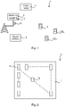
- a wireless network 1 comprises a number of network nodes 2 (only one illustrated in figure 1 ) enabling wireless communication for communication devices 3 by providing wireless links.
- the wireless network 1 may for instance be a 5G network (5 th Generation wireless network) or a Long Term Evolution (LTE) network.
- the network nodes 2 enabling the communication devices 3 to communicate over the wireless links may be denoted in different ways, e.g. radio access node, base station, radio base station, evolved node B (eNB) etc., depending e.g. on the particular type of network.
- the network node 2 is denoted base station 2.
- the base station 2 may provide coverage within a certain geographic area, denoted cell.
- One base station 2 may control one or more such cells.
- the base station 2 comprises or controls an antenna system 5 for receiving signaling from the UEs 3 and for transmitting signaling to the UEs 3.
- the antenna system 5 may comprise a number of antennas 7 and receiving circuitry and transmitting circuitry 8.
- the base station 2 is a MIMO base station, and in particular a massive MIMO base station 2. That is, the base station 2 comprises or controls a large, or very large number of antenna arrays, e.g. hundreds of phase-coherent antenna elements.
- the antenna system 5 may comprise linear antenna arrays, planar antenna arrays and may comprise single polarized antenna elements or multiple polarized antenna elements.
- the antenna arrays may be distributed or collocated, and may be vertical, horizontal, two or three dimensional.
- the antenna array configuration may for instance be a rectangular, spherical or cylindrical antenna array configuration. It is thus noted that the present disclosure is not limited to any particular configuration or deployment scenario of the antenna system 5. In this context it is also noted that massive MIMO is known also as, for instance, large-scale antenna system or very large MIMO.
- the communication devices 3 may be denoted in different ways, e.g. mobile station, wireless device, user equipment (UE), etc.
- the communication device 3 is in the following denoted user terminal or UE 3 and may comprise e.g. a smart phone, a tablet etc.
- the wireless network 1 further typically comprises various other network nodes, such as Mobility Management Entity (MME), operation and maintenance (O&M) nodes, packet data network gateways, mobility management entities, serving gateways etc.
- MME Mobility Management Entity
- O&M operation and maintenance
- packet data network gateways packet data network gateways
- mobility management entities mobility management entities
- serving gateways serving gateways etc.
- One such other network node is illustrated as central network node with reference numeral 4.
- FIG. 2 illustrates schematically an exemplary antenna system 5.
- the illustrated antenna system 5 comprises a planar antenna array 7 comprising a number of antenna elements 6 1 ,..., 6 i ,...
- An antenna system 5 is typically intended to encompass the antenna(s) and mechanical and electrical parts (indicated schematically at reference numeral 8 in figure 1 ) needed for functioning, e.g. transmitting/receiving circuitry and components.
- the antenna in turn may, as mentioned, comprise a number of antenna elements.
- the base station 2 is configurable for using beamforming (or spatial filtering), which is a signal processing technique used in antenna arrays for directional signal transmission or reception.
- each antenna element 6 1 ,..., 6 i ,... may be multiplied with a respective beamforming weight (creating the beamforming vector) and the weighted signals are added together forming the output signal to be transmitted.
- a feature of massive MIMO channel is that there is an excess of degrees of freedom in the downlink, and in particular many unused degrees of freedom in the downlink.
- the present disclosure discloses methods and means exploiting this fact, i.e. utilizing the many degrees of freedom in the base station that transmits control information as well as dedicated user data.
- a resource block is intended to encompass e.g. a time-frequency resource.
- a resource block may comprise a number of subcarriers and Orthogonal frequency-division multiplexing (OFDM) symbols in an OFDM access (OFDMA) based system.
- OFDM Orthogonal frequency-division multiplexing
- a total bandwidth may comprise of a number of resource blocks, wherein a resource block is the smallest resource that can be assigned to a user terminal.
- the excess degrees of freedom are exploited as follows: In each resource block, the base station 2 simultaneously
- the "null space” may be defined in a less mathematical way as the dimensions of the channel that are free, wherein “non-free" dimensions are the ones reserved for the UEs for which beamformed data is transmitted.
- the null space may be described as the degrees of freedom in the channel where it is essentially possible to transmit the same number of signals as degrees of freedom without causing any interference between the signals.
- the user terminals to which beamforming is performed are denoted "B-terminals", and all other terminals are denoted "O-terminals”.
- the beamforming vectors for the B-terminals are orthogonal to the null space, in which null space control information to O-terminals is broadcast. Hence, no co-channel interference exists between the terminals.
- the present teachings is applicable also for cases wherein the beamforming vectors for the B-terminals are close to orthogonal, or essentially orthogonal, to the null space. That is, although perfectly orthogonal is a preferred scenario, other cases are also applicable.
- the mathematical null space may be extended to encompass cases wherein small deviations ⁇ from zero are acceptable and within the scope of the disclosure. As long as interference caused by the deviation ⁇ from zero is small compared to other interference and noise, ⁇ will not substantially impact the performance.
- the B-terminals will not experience any interference from the information targeting the O-terminals, and vice versa.
- MAC media access control
- the broadcast information uses, in an embodiment, a diversity transmission scheme in the null space of the active B-terminals, the B-terminals are not able to decode that information in the particular resource blocks used for conveying data transmissions to the B-terminals.
- the base station 2 transmits the M-sized vector defined in Eq. (1).
- the k th B-terminal receives g k (denoting the channel gain vector between the base station and user k) multiplied by the transmitted vector in Eq. (1), plus noise (denoted by wk here).
- the base station 2 may send any vector, which lies in the null space of G T .
- the UE 3 is aware of that the wireless network 1 transmits broadcast information in a specific time/frequency resource, e.g. by being configured for this, but may disregard from decoding the broadcast information if user-specific data (e.g. unicast or multicast) is received.
- user-specific data e.g. unicast or multicast
- broadcast data is used to ensure coverage from the serving node, where a UE 3 may terminate the connection to a serving node if the quality of the broadcast data reaches below a threshold.
- quality of broadcast information is only estimated when no user-specific data transmission is received.
- Figure 3 illustrates processing 10 in a network node, for instance a base station 2 utilizing massive MIMO technology, for implementing aspects of the present disclosure.
- the term "resource” is used.
- the resource could for instance be a resource block as used within LTE, or some other time, frequency or code resource. It is thus noted that the way radio resources are divided into resource entities is not important for the present disclosure, and that the user specific data and the control data are transmitted in the same resource entity (as has been described), irrespective of denotation or division.
- the base station 2 may for instance be aware of a certain UE by the UE being in connected state.
- the base station 2 thus obtains G T [g 1 , ...g K ] T , wherein g k is the channel response in a particular resource from the antenna array to UE k .
- user data s k (t) is to be transmitted using the beamforming vector vk.
- the product v k s k (t) is determined.
- encoded control information z(t) (or broadcast information z(t)), received from an encoder, is to be transmitted using the beamforming matrix U.
- the product Uz(t) is determined.
- a resource is considered as a two-dimensional unit, the dimensions being frequency and time.
- a resource block is made up of one time slot in time domain and 12 sub-carriers (also denoted channels) in frequency domain, wherein a time slot is part of a so-called frame and comprises a number of symbols.
- Each frame may be divided into a number of sub-frames and each subframe is a number of time slots in the time dimension.
- 1 frame comprises 10 sub-frames, and a resource block spans one scheduling period, which is equal to (in time dimension) one subframe.
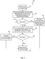
- Figure 4 illustrates a procedure in a user terminal according to an aspect of the present disclosure, not covered by the claimed invention.
- the procedure 20 starts at box 21, wherein processing of frame t is started.
- the flow continues to box 22, wherein the user terminal tries to demodulate and decode dedicated information s k (t) that potentially is present in a beamformed signal.
- box 23 If (box 23) the demodulation and decoding of box 22 is successful, flow continues to box 24, wherein the user terminal processes the received user plane data and any in-band control information that may be included in the signal. The flow then continues, from box 24 to box 27, wherein the processing of frame t ends.
- box 23 If (box 23) the user terminal did not succeed in the demodulation and decoding of box 22, the flow continues to box 25.
- box 25 the user terminal tries to demodulate and decode broadcast information z(t) that potentially is present in the signal.
- box 26 If (box 26) the user terminal succeeds demodulating and decoding broadcast information z(t), then flow continues to box 28, wherein the received broadcast information is processed. The flow then continues, from box 28 to box 27, wherein the processing of frame t ends.
- box 26 If (box 26) the user terminal did not succeed in the demodulation and decoding of box 25, the flow continues to box 27. In box 27, wherein the processing of frame t ends.
- Figure 5 illustrates a flow chart over steps of a method in a network node in accordance with the present disclosure.
- the various features that have been described may be combined in different ways, examples of which are described next with reference to figure 5 .
- a method 30 is provided which may be performed in a network node 2 for transmitting data in a wireless network 1.
- the network node 2 may for instance transmit multiple data streams.
- the network node 2 is configurable (or arranged) to control a multiple input multiple output antenna system 5.
- the network node 2 may for instance comprises a base station, a eNB etc. as has been described earlier.
- the method 30 comprises beamforming 31 user specific data streams to one or more communication devices, UE 1 ,..., UE K , wherein the beamforming 31 is based on respective channel information available for each of the one or more communication devices, UE 1 ,..., UE K .
- the method 30 comprises precoding 32 control information streams using a transmit diversity scheme.
- Such transmit diversity scheme may for instance be space-time block coding scheme (a particular example of which is Alamouti coding) or space-frequency block coding scheme.
- the method 30 comprises transmitting 33 the beamformed user specific data streams and the precoded control information streams in a same transmission resource.
- a particular example of a transmission resource to use is a resource block.
- the method 30 enables the resources (e.g. time and frequency resources) that are needed for transmission or broadcasting of control information to be used also for transmission of massive MIMO beamformed user data.
- the method thereby enhances the network capacity as well as the throughput for active users.
- the method may be used for transmission of multiple data streams, wherein at least one stream is transmitted using a directivity format and at least one stream is transmitted using a diversity format.
- a directivity beamforming format may be determined for a first data stream to a first user based on channel state information knowledge.
- the directivity beamforming format may be determined by different known methods, e.g. Maximum ratio transmission (MRT) or zero forcing.
- MRT Maximum ratio transmission
- a diversity transmission format causing limited interference to the directivity format may then be determined, e.g. by determining space time block codes (e.g. Alamouti codes) or determining space frequency block codes or using precoder cycling.
- the diversity transmission format determined may then be projected onto the orthogonal complement of a space spanned by channel gain vectors of the users for which the directivity beamforming is used.
- the first data stream is transmitted using the directivity transmission format on a first communication resource, e.g. a first time and frequency resource
- a second data stream is transmitted using the diversity transmission format on a communication resource, e.g. a time and frequency resource, at least partly overlapping with the first communication resource.
- the radio resources are divided into entities (communication resources) the first and second data streams are sent entirely in the same communication resources or sent partly overlapping.
- the precoding 32 comprises determining a precoding matrix to be in a nullspace of a combined channel matrix comprising a respective channel matrix for each of the one or more communication devices, UE 1 ,..., UE K .
- the precoding 32 comprises determining a precoding matrix to be within a nullspace + ⁇ of a combined channel matrix comprising a respective channel matrix for each of the one or more communication devices, UE 1 ,..., UE K , wherein the nullspace + ⁇ ⁇ threshold value.
- the threshold value may for instance be set in view of tolerable interference, which may depend on the circumstances of the particular set-up.
- the method 30 comprises instructing a communication device to which a beamformed user specific data stream is transmitted, on decoding of common control information.
- the network node may instruct the communication device to not try to decode the common control information. In particular, only when the communication device is explicitly instructed to not decode the common control channels, it may ignore to do so. To this end, the network node may for instance send information to the communication device to not decode the common control channel. This information may for instance be sent as a bit of a header of a particular message.
- the instructing comprises indicating, in a bit of a control message, e.g. in a scheduling assignment or a MAC header, the communication device to decode common control information in-band.
- the instructing comprises indicating in a bit of a control message the communication device to ignore common control information.
- the method 30 comprises, upon need to communicate control information to a communication device, UE 1 ,..., UE K , for which a user specific data stream is being beamformed, including the control information in the beamforming 31.
- the network node 2 may also communicate beamformed control information to the communication device for which beamformed user data is sent. Gains of massive MIMO can thereby be exploited also for the transmission of control information.
- Figure 6 illustrates schematically a network node and means for implementing methods of the present disclosure.
- the network node 2 comprises a processor 40 comprising any combination of one or more of a central processing unit (CPU), multiprocessor, microcontroller, digital signal processor (DSP), application specific integrated circuit etc. capable of executing software instructions stored in a memory 41, which can thus be a computer program product 41.
- the processor 40 can be configured to execute any of the various embodiments of the method 30 as has been described for instance in relation to figure 5 .
- the memory 41 can for instance be any combination of random access memory (RAM) and read only memory (ROM), Flash memory, magnetic tape, Compact Disc (CD)-ROM, digital versatile disc (DVD), Blueray disc etc.
- the memory 41 may also comprises persistent storage, which, for example, can be any single one or combination of magnetic memory, optical memory, solid state memory or even remotely mounted memory.
- the network node 2 may comprise or be configured to control a number of antennas 7, e.g. as described with reference to figures 1 and 2 , for providing wireless communication to communication devices, in particular by transmitting and/or receiving signaling to/from the communication devices within its coverage area(s).
- the network node 2 may also comprise receiving circuitry 43 and transmitting circuitry 44 for this purpose.
- the network node 2 comprises means for beamforming 45.
- a beamformer may be implemented using software instructions such as computer program executing in a processor and/or using hardware, such as application specific integrated circuits, field programmable gate arrays, discrete logical components etc.
- the network node 2 comprises means for precoding 47.
- the precoder may be implemented using software instructions such as computer program executing in a processor and/or using hardware, such as application specific integrated circuits, field programmable gate arrays, discrete logical components etc.
- the network node 2 may comprise still other means and functions, conventionally provided in a network node, for instance an input/output device 46 (I/O or IN/OUT) constituting an interface for communication exchange with e.g. other network nodes.
- I/O or IN/OUT input/output device 46
- a data memory may also be provided for reading and/or storing data during execution of software instructions in the processor 40.
- Such data memory may for instance be any combination of random access memory (RAM) and read only memory (ROM).
- a network node 2 is provided for transmitting data in a wireless network 1, wherein the network node 2 is configurable for controlling a multiple input multiple output antenna system 5.
- the network node 2 may be configured to control the MIMO antenna system 5 e.g. by comprising one or more processors 40 and memory, wherein the memory contains instructions executable by the processor 40, whereby the network node 2 is operative to perform e.g. the method 30 as described in various embodiments with reference to figure 5 .
- the network node 2 is configured to:
- the network node 2 is configured to precode by determining a precoding matrix to be in a nullspace of a combined channel matrix comprising a respective channel matrix for each of the one or more communication devices, UE 1 ,..., UE K .
- the network node 2 is configured to precode by determining a precoding matrix to be within a nullspace + ⁇ of a combined channel matrix comprising a respective channel matrix for each of the one or more communication devices, UE 1 ,..., UE K , wherein the nullspace + ⁇ ⁇ threshold value.
- the threshold value may have been set in view of tolerable interference, and e.g. be a preconfigured value obtainable by the network node 2.
- the network node 2 is configured to instruct a communication device to which a beamformed user specific data stream is transmitted, on decoding of common control information.
- the network node 2 is configured to instruct by indicating in a bit of a control message the communication device to decode common control information in-band.
- the network node 2 is configured to instruct by indicating in a bit of a control message the communication device to ignore common control information.
- the network node 2 is configured to, upon need to communicate control information to a communication device, UE 1 ,..., UE K , for which a user specific data stream is being beamformed, include the control information in the beamforming 31.
- the present disclosure also encompasses a computer program 42 for implementing the embodiments of the method, for instance as described above.
- the computer program 42 may be used in the network node 2 for transmitting data, the computer program 42 comprising computer program code, which, when executed on at least one processor 40 on the network node 2 causes the network node 2 to perform the method 30 as described e.g. in relation to figure 5 .
- the present disclosure also encompasses a computer program product 41 comprising a computer program 42 as above and a computer readable means on which the computer program 42 is stored.
- the present disclosure provides, in an aspect, a network node 2 for transmitting data in a wireless network 1.
- the network node 2 comprises first means for beamforming user specific data streams to one or more communication devices, UE 1 ,..., UE K , wherein the beamforming is based on respective channel information available for each of the one or more communication devices, UE 1 ,..., UE K .
- Such first means may (as mentioned earlier) be implemented as software instructions such as computer program executing in a processor and/or using hardware, such as application specific integrated circuits, field programmable gate arrays, discrete logical components etc.
- the first means 45 may comprise processing circuitry adapted to beamform by using program code stored in a memory.
- the network node 2 comprises second means for precoding control information streams using a transmit diversity scheme.
- Such second means may (as mentioned earlier) be implemented as software instructions such as computer program executing in a processor and/or using hardware, such as application specific integrated circuits, field programmable gate arrays, discrete logical components etc.
- the second means 47 may comprise processing circuitry adapted to precode by using program code stored in a memory.
- the network node 2 comprises third means 44 for transmitting the beamformed user specific data streams and the precoded control information streams in a same transmission resource.
- the third means 44 may for instance comprise processing circuitry configured for transmitting data streams, via e.g. antenna devices.
- the network node 2 may comprise still additional means for implementing the various embodiment of the present disclosure.
- Figure 7 illustrates a flow chart over steps of a method in a communication device in accordance with an aspect of the present disclosure, not covered by the claimed invention.
- the method 50 is performed in a communication device 3 for receiving data in a wireless network 1.
- the method 50 comprises receiving 51 a signal and initiating frame processing.
- the method 50 comprises determining 52 whether the signal comprises user specific data
- the communication device 3 determines whether the signal comprises control information.
- the procedure may for instance be implemented in a mobile station wherein the mobile station that receives a data stream with a directivity transmission format (e.g. beamformed user data) is not required to simultaneously receive and decode a second data stream with a diversity transmission format (e.g. precoded control information).
- the method 50 comprises, upon determining that there is control information in the signal, processing the control information and upon determining that there is no control information in the signal, ending the frame processing.
- the method 50 comprises disregarding decoding data on the configured control information resource upon determining that there is user specific data in the signal.
- the determining 52 whether the signal comprises user specific data comprises trying to demodulate and decode user specific data from the signal. In an embodiment, the determining presence of control information in the signal comprises trying to demodulate and decode control information from the signal.
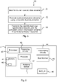
- Figure 8 illustrates schematically a communication device and means for implementing embodiments of methods of the present disclosure, not covered by the claimed invention.
- the communication device 3 comprises a processor 60 comprising any combination of one or more of a central processing unit (CPU), multiprocessor, microcontroller, digital signal processor (DSP), application specific integrated circuit etc. capable of executing software instructions stored in a memory 61, which can thus be a computer program product 61.
- the processor 60 can be configured to execute any of the various embodiments of the method 50 as has been described for instance in relation to figure 7 .
- the memory 61 can for instance be any combination of random access memory (RAM) and read only memory (ROM), Flash memory, magnetic tape, Compact Disc (CD)-ROM, digital versatile disc (DVD), Blueray disc etc.
- the memory 61 may also comprises persistent storage, which, for example, can be any single one or combination of magnetic memory, optical memory, solid state memory or even remotely mounted memory.
- the communication device 3 may comprise an antenna device 65 for receiving and transmitting wireless signaling from/to the network node 2.
- Receiving circuitry 63 and transmitting circuitry 64 may also be included for this end.
- the communication device 3 may comprise still other means and functions, conventionally provided in a communication device 3, for instance decoder 66, display (not illustrated) etc.
- Other examples comprises means 68 for processing user data, means 67 for determining presence of user data and means 69 for determining presence of control data, all of which are described more later.
- a data memory may also be provided for reading and/or storing data during execution of software instructions in the processor 60.
- Such data memory may for instance be any combination of random access memory (RAM) and read only memory (ROM).
- a communication device 3 is provided for receiving data in a wireless network 1.
- the communication device 3 is configured to perform e.g. the method 50 as described with reference to figure 7 .
- the network node 2 may be configured to receive the data e.g. by comprising one or more processors 60 and memory, wherein the memory contains instructions executable by the processor 60, whereby the communication device 3 is operative to perform e.g. the method 50 as described in various embodiments with reference to figure 7 .
- the communication device 3 is configured to:
- the communication device 3 is configured to, upon determining that there is control information in the signal, process the control information and upon determining that there is no control information in the signal, ending the frame processing.
- the communication device 3 is configured to receive control information in a control information resource, and to disregard decoding on the configured control information resource upon determining that there is user specific data in the signal.
- the communication device 3 is configured to determine whether the signal comprises user specific data by trying to demodulate and decode user specific data from the signal.
- the communication device 3 is configured to determine presence of control information in the signal by trying to demodulate and decode control information from the signal.
- the present disclosure also encompasses a computer program 62 for implementing the embodiments of the method, for instance as described above.
- the computer program 62 may be used in the communication device for receiving data, the computer program 62 comprising computer program code, which, when executed on at least one processor 60 on the communication device 3 causes the communication device 3 to perform the method 50 as described e.g. in relation to figure 7 .
- the present disclosure also encompasses a computer program product 61 comprising a computer program 462 as above and a computer readable means on which the computer program 62 is stored.
- FIG 8 An example of an implementation using functions modules/software modules is also illustrated in figure 8 , in particular illustrating the communication device 3 comprising means for implementing embodiments of the methods of the present disclosure.
- the present disclosure also provides, in an aspect, a communication device 3 for receiving data in a wireless network 1.
- the communication device 3 comprises first means for receiving a signal and initiating frame processing.
- Such first means may for instance comprise processing circuitry configured for receiving signaling, e.g. receiving circuitry 63, via antenna device 65.
- the communication device 3 comprises second means for determining whether the signal comprises user specific data.
- Such second means may comprise processing circuitry, e.g. as indicated at reference numeral 67 of figure 8 , adapted to perform such determination by using program code stored in a memory.
- the communication device 3 comprises third means for processing the user specific data upon determining that there is user specific data in the signal.
- the third means may be implemented by processing circuitry, e.g. as indicated at reference numeral 68 of figure 8 , adapted to process the user specific data by using program code stored in a memory and/or e.g. using decoding means 66.
- the communication device 3 comprises fourth means for determining whether the signal comprises control information upon determining that there is no user specific data in the signal.
- the fourth means may be implemented by processing circuitry, e.g. as indicated at reference numeral 69 of figure 8 , adapted to perform such determination whether there is control information in the signal by using program code stored in a memory.
- the first means, the second means, the third means and the fourth means above may be implemented as software instructions such as computer program executing in a processor and/or using hardware, such as application specific integrated circuits, field programmable gate arrays, discrete logical components etc.
Landscapes
- Engineering & Computer Science (AREA)
- Signal Processing (AREA)
- Computer Networks & Wireless Communication (AREA)
- Power Engineering (AREA)
- Physics & Mathematics (AREA)
- Mathematical Physics (AREA)
- Mobile Radio Communication Systems (AREA)
- Radio Transmission System (AREA)
Claims (6)
- Verfahren (30), das auf einem Netzwerkknoten (2) zum Senden von Daten in einem drahtlosen Netzwerk (1) durchgeführt wird, wobei der Netzwerkknoten (2) zum Steuern eines Antennensystem (5) mit Mehrfacheingabe und Mehrfachausgabe konfigurierbar ist, wobei das Verfahren (30) Folgendes umfasst:- Strahlformen (31) von benutzerspezifischen Datenströmen {sk(t)} an eine oder mehrere Kommunikationsvorrichtungen, UEk, k=1,...K, unter Verwendung von jeweiligen Strahlformungsvektoren {Vk}, wobei die Strahlformungsvektoren {Vk} auf jeweiligen Kanalinformationen {gk} basieren, die für die jeweiligen Kommunikationsvorrichtungen, UEk, verfügbar sind,- Vorcodieren (32) von Steuerinformationsströmen unter Verwendung eines Sendediversitätsschemas, und- Senden (33) der strahlgeformten benutzerspezifischen Datenströme und der vorcodierten Steuerinformationsströmen simultan in der gleichen Zeit- und Frequenzressource, wobei Vorcodieren (32) Bestimmen einer Vorcodierungsmatrix umfasst, die in einem Nullraum einer kombinierten Kanalmatrix liegen muss, die eine jeweilige Kanalmatrix für jede der einen oder mehreren Kommunikationsvorrichtungen, UEk, k=i,..., K, umfasst.
- Verfahren (30) nach Anspruch 1, umfassend Anweisen einer Kommunikationsvorrichtung, an die ein strahlgeformter benutzerspezifischer Datenstrom gesendet wird, gemeinsame Steuerinformationen zu codieren.
- Verfahren (30) nach Anspruch 2, wobei Anweisen umfasst, der Kommunikationsvorrichtung in einem Bit einer Steuernachricht anzuzeigen, die gemeinsamen Steuerinformationen innerhalb des Bandes zu decodieren.
- Verfahren (30) nach Anspruch 2 oder 3, wobei Anweisen umfasst, der Kommunikationsvorrichtung in einem Bit einer Steuernachricht anzuzeigen, die gemeinsamen Steuerinformationen zu ignorieren.
- Verfahren (30) nach einem der vorstehenden Ansprüche, umfassend, bei Bedarf, Steuerinformationen an eine Kommunikationsvorrichtung, UE1,..., UEK, zu kommunizieren, für die ein benutzerspezifischer Datenstrom strahlgeformt wird, Einschließen der Steuerinformationen in das Strahlformen (31).
- Netzwerkknoten (2) zum Senden von Daten in einem drahtlosen Netzwerk (1), wobei der Netzwerkknoten (2) zum Steuern eines Antennensystems (5) mit Mehrfacheingabe und Mehrfachausgabe konfigurierbar ist, wobei der Netzwerkknoten (2) konfiguriert ist, um:- benutzerspezifische Datenströme {Sk(t)} an eine oder mehrere Kommunikationsvorrichtungen, UEk, k=1,...K, unter Verwendung von jeweiligen Strahlformungsvektoren {Vk} zu strahlformen (31), wobei die Strahlformungsvektoren {Vk} auf jeweiligen Kanalinformationen {gk} basieren, die für die jeweiligen Kommunikationsvorrichtungen, UEk, verfügbar sind,- Steuerinformationsströmen unter Verwendung eines Sendediversitätsschemas zu vorcodieren (32), und- die strahlgeformten benutzerspezifischen Datenströme und der vorcodierten Steuerinformationsströmen simultan in der gleichen Zeit- und Frequenzressource zu senden, wobei Vorcodieren Bestimmen einer Vorcodierungsmatrix umfasst, die in einem Nullraum einer kombinierten Kanalmatrix liegen muss, die eine jeweilige Kanalmatrix für jede der einen oder mehreren Kommunikationsvorrichtungen, UEk, k=i,..., K, umfasst.
Applications Claiming Priority (1)
| Application Number | Priority Date | Filing Date | Title |
|---|---|---|---|
| PCT/SE2014/051163 WO2016056955A1 (en) | 2014-10-07 | 2014-10-07 | Methods, network node and communication device for transmitting data |
Publications (3)
| Publication Number | Publication Date |
|---|---|
| EP3205031A1 EP3205031A1 (de) | 2017-08-16 |
| EP3205031A4 EP3205031A4 (de) | 2018-02-14 |
| EP3205031B1 true EP3205031B1 (de) | 2022-06-29 |
Family
ID=55653440
Family Applications (1)
| Application Number | Title | Priority Date | Filing Date |
|---|---|---|---|
| EP14903749.1A Active EP3205031B1 (de) | 2014-10-07 | 2014-10-07 | Verfahren, netzwerkknoten und kommunikationsvorrichtung zur datenübertragung |
Country Status (7)
| Country | Link |
|---|---|
| US (2) | US10050691B2 (de) |
| EP (1) | EP3205031B1 (de) |
| JP (1) | JP6476279B2 (de) |
| KR (1) | KR20170046697A (de) |
| CN (1) | CN106797240B (de) |
| MX (1) | MX365929B (de) |
| WO (1) | WO2016056955A1 (de) |
Families Citing this family (7)
| Publication number | Priority date | Publication date | Assignee | Title |
|---|---|---|---|---|
| CN106797240B (zh) | 2014-10-07 | 2021-01-12 | 瑞典爱立信有限公司 | 用于传送数据的方法、网络节点和装置 |
| EP3298430B1 (de) * | 2015-05-18 | 2020-07-08 | King Abdullah University Of Science And Technology | Direkte kovarianzmatrix mit geschlossener form und endlichen alphabet-wellenformen mit konstanter hüllkurve für planare arraystrahlmuster |
| CN107396443B (zh) * | 2016-05-13 | 2022-07-12 | 中兴通讯股份有限公司 | 一种控制信息的发送方法、检测方法、基站和终端 |
| WO2019154517A1 (en) * | 2018-02-12 | 2019-08-15 | Nokia Technologies Oy | Coordinated precoding and beamforming of position purpose signals |
| CN111919395A (zh) * | 2018-02-13 | 2020-11-10 | 瑞典爱立信有限公司 | 无线通信网络中用于信号传输和接收的方法和装置 |
| US11122574B2 (en) * | 2018-08-08 | 2021-09-14 | Qualcomm Incorporated | Indication of antenna coherence for phase difference of arrival and angle of departure estimation |
| KR102500955B1 (ko) * | 2021-08-30 | 2023-02-17 | 광운대학교 산학협력단 | IoT 네트워크를 위한 무인항공기를 활용한 동시 무선 정보 및 전력 전송방법 |
Family Cites Families (11)
| Publication number | Priority date | Publication date | Assignee | Title |
|---|---|---|---|---|
| US8009617B2 (en) * | 2007-08-15 | 2011-08-30 | Qualcomm Incorporated | Beamforming of control information in a wireless communication system |
| WO2010002734A2 (en) * | 2008-06-30 | 2010-01-07 | Interdigital Patent Holdings, Inc. | Method and apparatus to support single user (su) and multiuser (mu) beamforming with antenna array groups |
| US8611313B2 (en) | 2008-08-27 | 2013-12-17 | Qualcomm Incorporated | Multiplexing of control information and data for wireless communication |
| JP2010206403A (ja) * | 2009-03-02 | 2010-09-16 | Toshiba Corp | 基地局、端末および無線通信システム |
| CN101668338B (zh) * | 2009-09-27 | 2012-01-04 | 新邮通信设备有限公司 | 在时分双工系统中实现多用户多输入多输出的方法和设备 |
| CN115767752A (zh) * | 2011-02-11 | 2023-03-07 | 交互数字专利控股公司 | 用于增强型控制信道的系统和方法 |
| KR20130050024A (ko) * | 2011-11-07 | 2013-05-15 | 주식회사 팬택 | 무선 통신 시스템에서 e-pdcch 매핑 및 송수신 방법 및 장치 |
| KR102207480B1 (ko) * | 2011-11-16 | 2021-01-26 | 삼성전자 주식회사 | 무선 통신 시스템에서 제어 정보 전송을 위한 방법 및 장치 |
| EP3402115A1 (de) * | 2012-01-30 | 2018-11-14 | Zte (Usa) Inc. | Effizientes multiplexen von epdcch-signalen |
| US9544876B2 (en) | 2012-03-16 | 2017-01-10 | Intel Corporation | Downlink control information (DCI) validation for enhanced physical downlink control channel (ePDCCH) |
| CN106797240B (zh) | 2014-10-07 | 2021-01-12 | 瑞典爱立信有限公司 | 用于传送数据的方法、网络节点和装置 |
-
2014
- 2014-10-07 CN CN201480082579.9A patent/CN106797240B/zh active Active
- 2014-10-07 JP JP2017507427A patent/JP6476279B2/ja active Active
- 2014-10-07 MX MX2017002168A patent/MX365929B/es active IP Right Grant
- 2014-10-07 US US15/500,171 patent/US10050691B2/en active Active
- 2014-10-07 EP EP14903749.1A patent/EP3205031B1/de active Active
- 2014-10-07 WO PCT/SE2014/051163 patent/WO2016056955A1/en not_active Ceased
- 2014-10-07 KR KR1020177007420A patent/KR20170046697A/ko not_active Ceased
-
2018
- 2018-07-10 US US16/031,658 patent/US10461830B2/en active Active
Also Published As
| Publication number | Publication date |
|---|---|
| CN106797240A (zh) | 2017-05-31 |
| US10050691B2 (en) | 2018-08-14 |
| EP3205031A4 (de) | 2018-02-14 |
| CN106797240B (zh) | 2021-01-12 |
| KR20170046697A (ko) | 2017-05-02 |
| JP6476279B2 (ja) | 2019-02-27 |
| EP3205031A1 (de) | 2017-08-16 |
| JP2017535092A (ja) | 2017-11-24 |
| MX2017002168A (es) | 2017-05-03 |
| MX365929B (es) | 2019-06-20 |
| US10461830B2 (en) | 2019-10-29 |
| WO2016056955A1 (en) | 2016-04-14 |
| US20170279511A1 (en) | 2017-09-28 |
| US20180323847A1 (en) | 2018-11-08 |
Similar Documents
| Publication | Publication Date | Title |
|---|---|---|
| US10461830B2 (en) | Methods, network node and communication device for transmitting data | |
| CN115136506B (zh) | 使用信道压缩和重构的信道状态信息反馈 | |
| CN115485986B (zh) | 基于经修改的类型ii端口选择码本的频率选择性单频网 | |
| KR102789988B1 (ko) | 차량 통신 시스템에서의 fd-mimo 기반의 멀티캐스팅 방법 및 장치 | |
| TWI590608B (zh) | 在多使用者之多輸入多輸出系統中的平行通道培訓技術 | |
| CN102859894B (zh) | 在无线通信系统中反馈信道状态信息的方法和用户设备装置 | |
| CN101611568B (zh) | 组合了对无线信号的循环延迟分集和预编码的方法和系统 | |
| US9660736B2 (en) | Systems, methods, and devices for interference mitigation in wireless networks | |
| CN108886434B (zh) | 基于ue-rs的开环以及半开环mimo | |
| CN103975546A (zh) | 无线基站装置、无线通信系统以及无线通信方法 | |
| CN110326351B (zh) | 用于在上行链路中提供显式反馈的系统和方法 | |
| WO2018058433A1 (zh) | 参考信号的传输装置、方法以及通信系统 | |
| CN109478987A (zh) | 用于处置通信的方法和用户设备 | |
| WO2024150208A1 (en) | Improving accuracy of artificial intelligence/machine learning (ai/ml) based channel state information (csi) feedback | |
| KR20250047300A (ko) | 코드북 서브세트 제약을 위한 방법 및 장치 | |
| CN118160231A (zh) | 无线通信的方法、终端设备和网络设备 | |
| WO2022066747A1 (en) | Device and method for performing csi reporting for type ii port selection codebook | |
| EP3444982A1 (de) | Verfahren, vorrichtung und system für kanalstatusinformationsfeedback | |
| US9960934B2 (en) | Channel estimation for FBMC modulation | |
| US20260107279A1 (en) | Method and apparatus for communications | |
| US20260121890A1 (en) | Method and apparatus for reporting channel information | |
| US20260113217A1 (en) | Communication method and related apparatus | |
| US20260113162A1 (en) | Communication method and related apparatus | |
| US10277371B2 (en) | System and method for handling orphan resource elements | |
| CN121241544A (zh) | 通信方法和通信装置 |
Legal Events
| Date | Code | Title | Description |
|---|---|---|---|
| STAA | Information on the status of an ep patent application or granted ep patent |
Free format text: STATUS: THE INTERNATIONAL PUBLICATION HAS BEEN MADE |
|
| PUAI | Public reference made under article 153(3) epc to a published international application that has entered the european phase |
Free format text: ORIGINAL CODE: 0009012 |
|
| STAA | Information on the status of an ep patent application or granted ep patent |
Free format text: STATUS: REQUEST FOR EXAMINATION WAS MADE |
|
| 17P | Request for examination filed |
Effective date: 20170127 |
|
| AK | Designated contracting states |
Kind code of ref document: A1 Designated state(s): AL AT BE BG CH CY CZ DE DK EE ES FI FR GB GR HR HU IE IS IT LI LT LU LV MC MK MT NL NO PL PT RO RS SE SI SK SM TR |
|
| AX | Request for extension of the european patent |
Extension state: BA ME |
|
| RIC1 | Information provided on ipc code assigned before grant |
Ipc: H04B 7/04 20170101AFI20170921BHEP Ipc: H04B 7/0456 20170101ALI20170921BHEP Ipc: H04L 5/00 20060101ALI20170921BHEP Ipc: H04L 25/03 20060101ALI20170921BHEP Ipc: H04W 72/04 20090101ALI20170921BHEP Ipc: H04B 7/06 20060101ALI20170921BHEP |
|
| DAX | Request for extension of the european patent (deleted) | ||
| STAA | Information on the status of an ep patent application or granted ep patent |
Free format text: STATUS: EXAMINATION IS IN PROGRESS |
|
| A4 | Supplementary search report drawn up and despatched |
Effective date: 20180116 |
|
| RIC1 | Information provided on ipc code assigned before grant |
Ipc: H04W 72/04 20090101ALI20180110BHEP Ipc: H04B 7/04 20170101AFI20180110BHEP Ipc: H04L 5/00 20060101ALI20180110BHEP Ipc: H04B 7/0456 20170101ALI20180110BHEP Ipc: H04B 7/06 20060101ALI20180110BHEP Ipc: H04L 25/03 20060101ALI20180110BHEP |
|
| 17Q | First examination report despatched |
Effective date: 20180205 |
|
| GRAP | Despatch of communication of intention to grant a patent |
Free format text: ORIGINAL CODE: EPIDOSNIGR1 |
|
| STAA | Information on the status of an ep patent application or granted ep patent |
Free format text: STATUS: GRANT OF PATENT IS INTENDED |
|
| INTG | Intention to grant announced |
Effective date: 20220225 |
|
| GRAS | Grant fee paid |
Free format text: ORIGINAL CODE: EPIDOSNIGR3 |
|
| GRAA | (expected) grant |
Free format text: ORIGINAL CODE: 0009210 |
|
| STAA | Information on the status of an ep patent application or granted ep patent |
Free format text: STATUS: THE PATENT HAS BEEN GRANTED |
|
| AK | Designated contracting states |
Kind code of ref document: B1 Designated state(s): AL AT BE BG CH CY CZ DE DK EE ES FI FR GB GR HR HU IE IS IT LI LT LU LV MC MK MT NL NO PL PT RO RS SE SI SK SM TR |
|
| REG | Reference to a national code |
Ref country code: GB Ref legal event code: FG4D |
|
| REG | Reference to a national code |
Ref country code: CH Ref legal event code: EP |
|
| REG | Reference to a national code |
Ref country code: AT Ref legal event code: REF Ref document number: 1502013 Country of ref document: AT Kind code of ref document: T Effective date: 20220715 |
|
| REG | Reference to a national code |
Ref country code: IE Ref legal event code: FG4D |
|
| REG | Reference to a national code |
Ref country code: DE Ref legal event code: R096 Ref document number: 602014084193 Country of ref document: DE |
|
| REG | Reference to a national code |
Ref country code: LT Ref legal event code: MG9D |
|
| PG25 | Lapsed in a contracting state [announced via postgrant information from national office to epo] |
Ref country code: SE Free format text: LAPSE BECAUSE OF FAILURE TO SUBMIT A TRANSLATION OF THE DESCRIPTION OR TO PAY THE FEE WITHIN THE PRESCRIBED TIME-LIMIT Effective date: 20220629 Ref country code: NO Free format text: LAPSE BECAUSE OF FAILURE TO SUBMIT A TRANSLATION OF THE DESCRIPTION OR TO PAY THE FEE WITHIN THE PRESCRIBED TIME-LIMIT Effective date: 20220929 Ref country code: LT Free format text: LAPSE BECAUSE OF FAILURE TO SUBMIT A TRANSLATION OF THE DESCRIPTION OR TO PAY THE FEE WITHIN THE PRESCRIBED TIME-LIMIT Effective date: 20220629 Ref country code: HR Free format text: LAPSE BECAUSE OF FAILURE TO SUBMIT A TRANSLATION OF THE DESCRIPTION OR TO PAY THE FEE WITHIN THE PRESCRIBED TIME-LIMIT Effective date: 20220629 Ref country code: GR Free format text: LAPSE BECAUSE OF FAILURE TO SUBMIT A TRANSLATION OF THE DESCRIPTION OR TO PAY THE FEE WITHIN THE PRESCRIBED TIME-LIMIT Effective date: 20220930 Ref country code: FI Free format text: LAPSE BECAUSE OF FAILURE TO SUBMIT A TRANSLATION OF THE DESCRIPTION OR TO PAY THE FEE WITHIN THE PRESCRIBED TIME-LIMIT Effective date: 20220629 Ref country code: BG Free format text: LAPSE BECAUSE OF FAILURE TO SUBMIT A TRANSLATION OF THE DESCRIPTION OR TO PAY THE FEE WITHIN THE PRESCRIBED TIME-LIMIT Effective date: 20220929 |
|
| REG | Reference to a national code |
Ref country code: NL Ref legal event code: MP Effective date: 20220629 |
|
| REG | Reference to a national code |
Ref country code: AT Ref legal event code: MK05 Ref document number: 1502013 Country of ref document: AT Kind code of ref document: T Effective date: 20220629 |
|
| PG25 | Lapsed in a contracting state [announced via postgrant information from national office to epo] |
Ref country code: RS Free format text: LAPSE BECAUSE OF FAILURE TO SUBMIT A TRANSLATION OF THE DESCRIPTION OR TO PAY THE FEE WITHIN THE PRESCRIBED TIME-LIMIT Effective date: 20220629 Ref country code: LV Free format text: LAPSE BECAUSE OF FAILURE TO SUBMIT A TRANSLATION OF THE DESCRIPTION OR TO PAY THE FEE WITHIN THE PRESCRIBED TIME-LIMIT Effective date: 20220629 |
|
| PG25 | Lapsed in a contracting state [announced via postgrant information from national office to epo] |
Ref country code: NL Free format text: LAPSE BECAUSE OF FAILURE TO SUBMIT A TRANSLATION OF THE DESCRIPTION OR TO PAY THE FEE WITHIN THE PRESCRIBED TIME-LIMIT Effective date: 20220629 |
|
| PG25 | Lapsed in a contracting state [announced via postgrant information from national office to epo] |
Ref country code: SM Free format text: LAPSE BECAUSE OF FAILURE TO SUBMIT A TRANSLATION OF THE DESCRIPTION OR TO PAY THE FEE WITHIN THE PRESCRIBED TIME-LIMIT Effective date: 20220629 Ref country code: SK Free format text: LAPSE BECAUSE OF FAILURE TO SUBMIT A TRANSLATION OF THE DESCRIPTION OR TO PAY THE FEE WITHIN THE PRESCRIBED TIME-LIMIT Effective date: 20220629 Ref country code: RO Free format text: LAPSE BECAUSE OF FAILURE TO SUBMIT A TRANSLATION OF THE DESCRIPTION OR TO PAY THE FEE WITHIN THE PRESCRIBED TIME-LIMIT Effective date: 20220629 Ref country code: PT Free format text: LAPSE BECAUSE OF FAILURE TO SUBMIT A TRANSLATION OF THE DESCRIPTION OR TO PAY THE FEE WITHIN THE PRESCRIBED TIME-LIMIT Effective date: 20221031 Ref country code: ES Free format text: LAPSE BECAUSE OF FAILURE TO SUBMIT A TRANSLATION OF THE DESCRIPTION OR TO PAY THE FEE WITHIN THE PRESCRIBED TIME-LIMIT Effective date: 20220629 Ref country code: EE Free format text: LAPSE BECAUSE OF FAILURE TO SUBMIT A TRANSLATION OF THE DESCRIPTION OR TO PAY THE FEE WITHIN THE PRESCRIBED TIME-LIMIT Effective date: 20220629 Ref country code: AT Free format text: LAPSE BECAUSE OF FAILURE TO SUBMIT A TRANSLATION OF THE DESCRIPTION OR TO PAY THE FEE WITHIN THE PRESCRIBED TIME-LIMIT Effective date: 20220629 |
|
| PG25 | Lapsed in a contracting state [announced via postgrant information from national office to epo] |
Ref country code: PL Free format text: LAPSE BECAUSE OF FAILURE TO SUBMIT A TRANSLATION OF THE DESCRIPTION OR TO PAY THE FEE WITHIN THE PRESCRIBED TIME-LIMIT Effective date: 20220629 Ref country code: IS Free format text: LAPSE BECAUSE OF FAILURE TO SUBMIT A TRANSLATION OF THE DESCRIPTION OR TO PAY THE FEE WITHIN THE PRESCRIBED TIME-LIMIT Effective date: 20221029 |
|
| REG | Reference to a national code |
Ref country code: DE Ref legal event code: R097 Ref document number: 602014084193 Country of ref document: DE |
|
| PG25 | Lapsed in a contracting state [announced via postgrant information from national office to epo] |
Ref country code: AL Free format text: LAPSE BECAUSE OF FAILURE TO SUBMIT A TRANSLATION OF THE DESCRIPTION OR TO PAY THE FEE WITHIN THE PRESCRIBED TIME-LIMIT Effective date: 20220629 |
|
| PG25 | Lapsed in a contracting state [announced via postgrant information from national office to epo] |
Ref country code: DK Free format text: LAPSE BECAUSE OF FAILURE TO SUBMIT A TRANSLATION OF THE DESCRIPTION OR TO PAY THE FEE WITHIN THE PRESCRIBED TIME-LIMIT Effective date: 20220629 Ref country code: CZ Free format text: LAPSE BECAUSE OF FAILURE TO SUBMIT A TRANSLATION OF THE DESCRIPTION OR TO PAY THE FEE WITHIN THE PRESCRIBED TIME-LIMIT Effective date: 20220629 |
|
| PLBE | No opposition filed within time limit |
Free format text: ORIGINAL CODE: 0009261 |
|
| STAA | Information on the status of an ep patent application or granted ep patent |
Free format text: STATUS: NO OPPOSITION FILED WITHIN TIME LIMIT |
|
| PG25 | Lapsed in a contracting state [announced via postgrant information from national office to epo] |
Ref country code: MC Free format text: LAPSE BECAUSE OF FAILURE TO SUBMIT A TRANSLATION OF THE DESCRIPTION OR TO PAY THE FEE WITHIN THE PRESCRIBED TIME-LIMIT Effective date: 20220629 |
|
| REG | Reference to a national code |
Ref country code: CH Ref legal event code: PL |
|
| 26N | No opposition filed |
Effective date: 20230330 |
|
| REG | Reference to a national code |
Ref country code: BE Ref legal event code: MM Effective date: 20221031 |
|
| PG25 | Lapsed in a contracting state [announced via postgrant information from national office to epo] |
Ref country code: LU Free format text: LAPSE BECAUSE OF NON-PAYMENT OF DUE FEES Effective date: 20221007 |
|
| PG25 | Lapsed in a contracting state [announced via postgrant information from national office to epo] |
Ref country code: LI Free format text: LAPSE BECAUSE OF NON-PAYMENT OF DUE FEES Effective date: 20221031 Ref country code: FR Free format text: LAPSE BECAUSE OF NON-PAYMENT OF DUE FEES Effective date: 20221031 Ref country code: CH Free format text: LAPSE BECAUSE OF NON-PAYMENT OF DUE FEES Effective date: 20221031 |
|
| PG25 | Lapsed in a contracting state [announced via postgrant information from national office to epo] |
Ref country code: SI Free format text: LAPSE BECAUSE OF FAILURE TO SUBMIT A TRANSLATION OF THE DESCRIPTION OR TO PAY THE FEE WITHIN THE PRESCRIBED TIME-LIMIT Effective date: 20220629 |
|
| PG25 | Lapsed in a contracting state [announced via postgrant information from national office to epo] |
Ref country code: BE Free format text: LAPSE BECAUSE OF NON-PAYMENT OF DUE FEES Effective date: 20221031 |
|
| PG25 | Lapsed in a contracting state [announced via postgrant information from national office to epo] |
Ref country code: IE Free format text: LAPSE BECAUSE OF NON-PAYMENT OF DUE FEES Effective date: 20221007 |
|
| PG25 | Lapsed in a contracting state [announced via postgrant information from national office to epo] |
Ref country code: IT Free format text: LAPSE BECAUSE OF FAILURE TO SUBMIT A TRANSLATION OF THE DESCRIPTION OR TO PAY THE FEE WITHIN THE PRESCRIBED TIME-LIMIT Effective date: 20220629 |
|
| PG25 | Lapsed in a contracting state [announced via postgrant information from national office to epo] |
Ref country code: HU Free format text: LAPSE BECAUSE OF FAILURE TO SUBMIT A TRANSLATION OF THE DESCRIPTION OR TO PAY THE FEE WITHIN THE PRESCRIBED TIME-LIMIT; INVALID AB INITIO Effective date: 20141007 |
|
| PG25 | Lapsed in a contracting state [announced via postgrant information from national office to epo] |
Ref country code: CY Free format text: LAPSE BECAUSE OF FAILURE TO SUBMIT A TRANSLATION OF THE DESCRIPTION OR TO PAY THE FEE WITHIN THE PRESCRIBED TIME-LIMIT Effective date: 20220629 |
|
| PG25 | Lapsed in a contracting state [announced via postgrant information from national office to epo] |
Ref country code: MK Free format text: LAPSE BECAUSE OF FAILURE TO SUBMIT A TRANSLATION OF THE DESCRIPTION OR TO PAY THE FEE WITHIN THE PRESCRIBED TIME-LIMIT Effective date: 20220629 |
|
| PG25 | Lapsed in a contracting state [announced via postgrant information from national office to epo] |
Ref country code: TR Free format text: LAPSE BECAUSE OF FAILURE TO SUBMIT A TRANSLATION OF THE DESCRIPTION OR TO PAY THE FEE WITHIN THE PRESCRIBED TIME-LIMIT Effective date: 20220629 |
|
| PG25 | Lapsed in a contracting state [announced via postgrant information from national office to epo] |
Ref country code: MT Free format text: LAPSE BECAUSE OF FAILURE TO SUBMIT A TRANSLATION OF THE DESCRIPTION OR TO PAY THE FEE WITHIN THE PRESCRIBED TIME-LIMIT Effective date: 20220629 |
|
| PG25 | Lapsed in a contracting state [announced via postgrant information from national office to epo] |
Ref country code: BG Free format text: LAPSE BECAUSE OF FAILURE TO SUBMIT A TRANSLATION OF THE DESCRIPTION OR TO PAY THE FEE WITHIN THE PRESCRIBED TIME-LIMIT Effective date: 20220629 |
|
| PG25 | Lapsed in a contracting state [announced via postgrant information from national office to epo] |
Ref country code: BG Free format text: LAPSE BECAUSE OF FAILURE TO SUBMIT A TRANSLATION OF THE DESCRIPTION OR TO PAY THE FEE WITHIN THE PRESCRIBED TIME-LIMIT Effective date: 20220629 |
|
| PGFP | Annual fee paid to national office [announced via postgrant information from national office to epo] |
Ref country code: DE Payment date: 20251029 Year of fee payment: 12 |
|
| PGFP | Annual fee paid to national office [announced via postgrant information from national office to epo] |
Ref country code: GB Payment date: 20251027 Year of fee payment: 12 |