EP3205193B1 - Gestängesteuerungssystem in einem fahrzeug - Google Patents
Gestängesteuerungssystem in einem fahrzeug Download PDFInfo
- Publication number
- EP3205193B1 EP3205193B1 EP17153066.0A EP17153066A EP3205193B1 EP 3205193 B1 EP3205193 B1 EP 3205193B1 EP 17153066 A EP17153066 A EP 17153066A EP 3205193 B1 EP3205193 B1 EP 3205193B1
- Authority
- EP
- European Patent Office
- Prior art keywords
- linkage
- vehicle
- implement
- draft
- height
- Prior art date
- Legal status (The legal status is an assumption and is not a legal conclusion. Google has not performed a legal analysis and makes no representation as to the accuracy of the status listed.)
- Active
Links
Images
Classifications
-
- A—HUMAN NECESSITIES
- A01—AGRICULTURE; FORESTRY; ANIMAL HUSBANDRY; HUNTING; TRAPPING; FISHING
- A01B—SOIL WORKING IN AGRICULTURE OR FORESTRY; PARTS, DETAILS, OR ACCESSORIES OF AGRICULTURAL MACHINES OR IMPLEMENTS, IN GENERAL
- A01B63/00—Lifting or adjusting devices or arrangements for agricultural machines or implements
- A01B63/002—Devices for adjusting or regulating the position of tools or wheels
- A01B63/008—Vertical adjustment of tools
-
- A—HUMAN NECESSITIES
- A01—AGRICULTURE; FORESTRY; ANIMAL HUSBANDRY; HUNTING; TRAPPING; FISHING
- A01B—SOIL WORKING IN AGRICULTURE OR FORESTRY; PARTS, DETAILS, OR ACCESSORIES OF AGRICULTURAL MACHINES OR IMPLEMENTS, IN GENERAL
- A01B63/00—Lifting or adjusting devices or arrangements for agricultural machines or implements
- A01B63/02—Lifting or adjusting devices or arrangements for agricultural machines or implements for implements mounted on tractors
- A01B63/10—Lifting or adjusting devices or arrangements for agricultural machines or implements for implements mounted on tractors operated by hydraulic or pneumatic means
- A01B63/111—Lifting or adjusting devices or arrangements for agricultural machines or implements for implements mounted on tractors operated by hydraulic or pneumatic means regulating working depth of implements
- A01B63/112—Lifting or adjusting devices or arrangements for agricultural machines or implements for implements mounted on tractors operated by hydraulic or pneumatic means regulating working depth of implements to control draught load, i.e. tractive force
-
- A—HUMAN NECESSITIES
- A01—AGRICULTURE; FORESTRY; ANIMAL HUSBANDRY; HUNTING; TRAPPING; FISHING
- A01B—SOIL WORKING IN AGRICULTURE OR FORESTRY; PARTS, DETAILS, OR ACCESSORIES OF AGRICULTURAL MACHINES OR IMPLEMENTS, IN GENERAL
- A01B63/00—Lifting or adjusting devices or arrangements for agricultural machines or implements
- A01B63/02—Lifting or adjusting devices or arrangements for agricultural machines or implements for implements mounted on tractors
- A01B63/10—Lifting or adjusting devices or arrangements for agricultural machines or implements for implements mounted on tractors operated by hydraulic or pneumatic means
- A01B63/118—Mounting implements on power-lift linkages
Definitions
- This invention concerns an implement detection arrangement for a tractor.
- a hitch such as a three-point linkage is one known arrangement used to attach implements to vehicle, for example an agricultural tractor for towing.
- the implement may be fully-mounted or semi-mounted whereby a semi-mounted implemented has a wheel engaging with the ground during soil operation while a fully-mounted implement puts all its load on the three-point linkage.
- Three point linkages most frequently consist of two lower lifting arms to which an implement is attached.
- the lower lifting arms can be pivoted by respective hydraulic actuating cylinders to adjust the height position of the implement relative to the ground.
- these lower lifting arms may be manually adjusted in length and thus be adapted to the type of implement to be attached.
- An additional top link connects the implement to the tractor on a level above the lower lifting arms. This top link is used to pivot the implement about a horizontal transverse axis and is adjustable by means of a threaded connection, or a hydraulic cylinder.
- draft control and intermix mode both referred to as draft control modes
- deactivating the draft modes results in that the system enters the position mode with no draft force influencing the lifting heights. It may, however be difficult to install a draft force sensing pin due to the complex three-dimensional geometry of a linkage.
- the applicant's pending application WO2013/053645 describes an electronic linkage control wherein the draft force sensing pin is omitted and the variation of the draft force of the linkage is determined from the variation in the hydraulic drive circuit pressure.
- such systems may also be used for implements which are simply towed by connection to e.g. a ball hitch, rather than being hitch-mounted.
- implements which are simply towed by connection to e.g. a ball hitch, rather than being hitch-mounted.
- Different to fully-mounted implements the weight of the implement mainly rests on the ground via the implement wheels, and actuators are provided on the implements controlling the linkage thereon to raise and lower the soil-engaging means.
- the actuators mainly hydraulic actuating cylinders similar to those used for three point linkages, are thereby supplied and controlled by the hydraulic supply system and valve arrangements of the tractor.
- an implement may be semi-mounted, which means that the implement is mounted to the lower lifting arms of the tractor and further may be equipped with a ground engaging wheel so that the weight of the implement rests on the lower links and the ground via the implement wheels.
- the linkage of the tractor and the linkage of the implement must be adjusted conjointly.
- linkage may be understood as not limited to a three-point linkage of a tractor, but may also include linkages to move soil-engaging means of towed implements.
- a draft control mode the operator sets a value indicative of an acceptable draft force (depending on the condition of the ground and desired vehicle speed). If the draft force then increases continuously because a plough in the ground has hit a rock, the draft control will move the linkage upwards and therefore the plough will move upwards so that the draft force is reduced. If the draft force is reduced, the draft control mode will operate to lower the linkage and the plough towards the ground again. In this way, the plough will automatically pass a rock in the ground avoiding damage to it.
- the operator can also manually adjust the height of the linkage by using a Depth Controller in the cab.
- a system may use a pressure sensor installed in the lifting cylinder of the linkage.
- an unloaded linkage may result in the lifting cylinders indicating a pressure of 11 bar.
- the pressure may change to about 15 bar as the ground supports some of the weight of the plough.
- the difference therefore between the implement being semi mounted for operation and an unloaded linkage is around 4 bar which can be too small a change in pressure to detect. It can therefore be difficult for a system to recognise whether an implement is attached or not.
- the pressure will be greater than 25 bar which can be easily detected.
- Position sensors can be used to detect the position of an attached implement, or trailer to the linkage, but the position of the linkage does not indicate whether an implement is attached.
- a tractor control unit may receive information by way of an ISOBUS system wherein an implement informs the tractor control unit of its attachment to the tractor.
- an electric supply/light connector, or fluid couplings on the tractor to which the implement is attached may be used to detect the attachment of an implement.
- these means do not provide information as to where the implement is attached, that is whether the implement is attached to the linkage or to a ball hitch, or at what height the implement is attached.
- known systems do not automatically disengage the draft control mode as a tractor comes to a standstill, is driven at very low speeds under 1 kph, or is driven in reverse. Under these operating conditions, where the draft force drops, there is a danger of the implement being unintentionally lowered.
- a vehicle according to the pre-characterising portion of claim 1 is disclosed in EP 2 889 515 A .
- the implement may be provided as fully-mounted to a linkage of the vehicle, e.g. on a three-point linkage on a tractor, or the implement may be provided as a trailed or semi-mounted implement wherein the vehicle is coupled with and controls the actuation of a linkage provided on the implement, a linkage provided on the tractor or linkages provided on both the implement and the tractor itself.
- controller for a vehicle as defined in claim 13 and a computer program product as defined in claim 14.
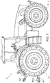
- an agricultural tractor 1 has a driveline 2 having a combustion engine 3, a continuously variable transmission (CVT), T of the hydrostatic-mechanical split type and a rear axle housing 300.
- Combustion engine 3 is connected to the CVT, T by chassis part 310.
- Rear wheels 2a and front wheels 2b are driven by driveline 2.
- a three-point linkage 400 is attached to the rear axle housing 300 and mainly consists of two lower lifting arms 401 to which an implement is attached.
- a plough 500 with ground engaging means 501 is attached to the lower lifting arms 401.
- An additional top link 402 connects the implement 500 to the tractor 1.
- the top link 402 is of a hydraulic type adjustable in length to adjust the inclination of the plough 500 with respect to the ground.
- the lower lifting arms 401 can be pivoted about axis A by respective hydraulic lifting cylinders 403 which move rocker arm 404 and lift rod 405.
- the height of the linkage can thus be changed by pivoting the lifting arms about axis A.
- height of the linkage it is meant the height of a part of the lifting arms relative to the ground.
- the height may be measured perpendicular to the ground, or otherwise.
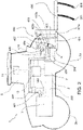
- the hydraulic actuating cylinders 403 are supplied with an actuating fluid by a control valve 406.
- Control valve 406 controls whether chamber 403a (for lifting the implement) or chamber 403b (for lowering the implement) of the hydraulic actuating cylinders 403 is charged with fluid.
- Control valve 406 is connected to a pump 407 which is driven by combustion engine 3 and connected to fluid tank 108.
- the position of the lower lifting arms 401 is indirectly measured by a position sensor 409 which senses the position of a cam 410 attached to rocker arm 404.
- An additional pressure sensor 411 is provided to measure the fluid pressure in the chamber 403a of the hydraulic actuating cylinders 403.
- the fluid in chamber 403a is compressed when the implement weight is fully taken up by the three-point linkage 400 and therefore a pressure increase indicates movement of the implement to a high position which is off the ground. Such a position is referred to as a transport position.
- a tractor control unit 13 is provided to control various functions of the vehicle.
- the control unit 13 is electronically connected to various components such as the transmission and display and input devices via a CAN-BUS system, for example.
- the control unit 13 also contains software to drive the electronic linkage control system.
- the control unit 13 is connected to an input and display device 14 in the tractor cab 5 to receive inputs from the operator and to show information to the operator.
- the input and display device 14 includes a means to adjust and display parameters relating to the electronic linkage control system, such as the mix controller or the depth controller described above.
- Position sensor 409, control valve 406 and pressure sensor 411 are connected to the control unit 13.
- the driveline 2 or transmission T may be of hydrostatic mechanical split type transmission.
- Driveline 2 or transmission T contains sensors to determine various driving parameters such as the draft force, the vehicle speed, the driving direction and whether the vehicle is stationary or not. Stationary here has its usual meaning of not moving or being at a standstill.
- this parameter can be used to control the linkage based on an increased draft force applied by the implement.
- an increase or decrease of the draft or pull force can be detected and processed by the electronic linkage control system to provide modes such as draft, intermix or position control modes.
- the change in draft force is fed into a tractor control unit 13 which is programmed to lift, or lower the linkage in response to the change as programmed.
- the detected draft force may be standardised and the standardised value forwarded to the control unit 13.
- the draft force is the force applied by the implement against the pull force of the tractor and is therefore applied in a direction opposite to the direction of travel of the tractor. If the speed of the tractor is kept constant, a change in pull force results in a change of draft force and vice versa.
- An implement may be attached to a ball hitch instead of the linkage, or stowed in transport position where it is fully lifted off the ground, or attached to the linkage for working where it does not contact the ground, or be semi mounted or fully mounted to the linkage.
- the term implement covers all tools, attachments and equipment which can be attached to a tractor, or agricultural machine at the front, or rear including, but not limited to the following: ploughs, tow bars, sprayers, mowers, drills and planters.
- the control system calculates the linkage height based on the height positon component HP only. However, in circumstances where the tractor is travelling at low speeds, or in reverse or is stationary and the linkage height is then further adjusted by the operator manually, for example by using a Depth Controller in the cab, the change of the height of the linkage will greater than if the draft control mode was active. If the tractor is then driven in a forwards direction at a higher speed, that is above 1kph, the control system changes automatically back to the draft control mode and the height draft component HD is used to determine the linkage height which results in an abrupt movement of the linkage which may de stabilise the tractor, or result in the implement contacting the ground and de coupling.
- the present invention addresses the aforementioned problems by the control system keeping the tractor in the draft control mode, setting the draft force to zero and holding the position of the linkage in a set or stable position, referred to as the set height when the tractor approaches low speeds, or travels in reverse, or is stationary.
- Setting the draft force to zero in accordance with the invention may mean that the draft force is set to zero by the control system, or that a standardised value representing a zero draft force zero is used by the control system.
- the present invention addresses the aforementioned problems by the control system keeping the tractor in the draft control mode by improving the detection of an implement.
- the control system detects whether an implement is attached to the linkage in the known manner by sensing the pressure in the hydraulic cylinders 403. If the pressure is greater than a pre-determined reference pressure, for example 25 bar, the control system registers that an implement is attached and the implement condition "IMPLEMENT ATTACHED" is set. As long as the vehicle speed is not reduced below a predetermined speed of 1.0kph, the implement condition "IMPLEMENT ATTACHED" is not changed even if the pressure in the cylinders 403 falls below the reference pressure.
- a pre-determined reference pressure for example 25 bar
- the control system Upon the tractor reaching a low speed below 1kph, the control system sets the draft force to zero which has the effect of setting the linkage in its current position at the set height.
- the position detector 409 records the height at which the linkage has been held or set, referred to as the set height. Since the implement condition "IMPLEMENT ATTACHED" is still active, the tractor is still in the draft control mode.
- the operator can then make manual adjustments to the height of the linkage using the Depth Controller. Such adjustments may result in that the implement is lowered to a height where it is partially or fully in contact with the ground and where it could de couple from the linkage. For this reason, the height of the linkage is monitored by position sensor 409 for a short monitoring period of around 5 seconds.
- a deviation of 3% or more from the set height has been chosen as being a height deviation at which the implement may decouple from the hooks 401a of the lower links 401 based on the geometry of the linkage and the position of the connection of the linkage to the tractor relative to the ground.
- the percentage deviation from the set height where de coupling is a possibility may vary for different vehicles.
- the system may also monitor a deviation in the upwards direction.
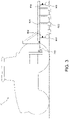
- a tractor 10 is shown which is coupled with a trailed implement 600 via a tow bar 200 or other suitable trailer connection.
- the trailed implement 600 which may comprise a plough or other similar tillage or soil cultivation apparatus, is provided with ground- or soil-engaging means 602, which are supported using at least one implement wheel 603.
- the height of the soil-engaging means 602, and accordingly their engagement with the ground is controlled through actuation of an implement-mounted linkage or lift cylinder 604 coupled to the implement wheels 603, but it will be understood that other implement linkage configurations may be used.
- the actuation of the linkage 604 is controlled via a suitable communication connection with the tractor control unit 13 (shown in Fig. 2 ), in a similar manner as described above for a linkage-mounted implement.
- the system may generate a warning and ask the operator to check if the implement is towed or semi-mounted instead and the implement is to be operated with draft force control. If the operator confirms, draft force mode would be kept active and the operator may be reminded to connect the respective hydraulic supply lines to the tractor to enable the vehicle control system to raise and lower the linkage of the implement accordingly.
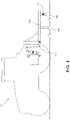
- a tractor 10 is shown which is coupled with a semi-mounted implement 700 via the lower lifting arms 401.
- the semi-mounted implement 700 which may comprise a plough or other similar tillage or soil cultivation apparatus, is also provided with ground- or soil-engaging means 702, which are partly supported using at least one implement wheel 703.
- the height of the soil-engaging means 702, and accordingly their engagement with the ground, is controlled through actuation of an implement-mounted linkage or lift cylinder 704 coupled to the implement wheel 703 and the lower lifting arms 401 conjointly, but it will be understood that other implement linkage configurations may be used.
- the actuation of the linkage 704 is controlled via a suitable communication connection with the tractor control unit 13 (shown in Fig. 2 ), in a similar manner as described above for a linkage-mounted implement.
- the system may generate a warning and ask the operator to check if the implement is towed or semi-mounted instead and the implement is to be operated with draft force control. If the operator confirms, draft force mode would be kept active and the operator may be reminded to connect the respective hydraulic supply lines to the tractor to enable the vehicle control system to raise and lower the linkage of the implement accordingly.
- the tractor travels above 1 kph in a forward direction, the tractor remains in the draft control mode and movement of the linkage is controlled as usual when in the draft control mode.
Landscapes
- Life Sciences & Earth Sciences (AREA)
- Engineering & Computer Science (AREA)
- Mechanical Engineering (AREA)
- Soil Sciences (AREA)
- Environmental Sciences (AREA)
- Lifting Devices For Agricultural Implements (AREA)
Claims (14)
- Fahrzeug, das eine Kopplung (400) zum Steuern/Regeln des Anhebens und Absenkens eines in den Boden eingreifenden Teils eines Arbeitsgeräts (500; 600; 700) steuert/regelt, wobei das Fahrzeug mindestens eine anzuhebende oder abzusenkende Kopplung (400), einen Sensor zum Feststellen einer Zugkraft, ein Steuer-/Regelsystem (13) mindestens für einen Betriebsmodus der Zugsteuerung/Zugregelung, in dem mindestens eine Kopplung (400) in Abhängigkeit von der durch das Fahrzeug festgestellten Zugkraft automatisch angehoben und abgesenkt wird, aufweist, wobei die Kopplung (400) einen Hebezylinder (403) und Sensoren zum Feststellen einer Geschwindigkeit und einer Bewegungsrichtung des Fahrzeugs aufweist; dadurch gekennzeichnet, dass bei einer Bewegung des Fahrzeugs mit niedrigen Geschwindigkeiten von 1 km/h oder weniger, einer Rückwärtsfahrt des Fahrzeugs oder einem Stillstand des Fahrzeugs das Steuer-/Regelsystem (13) geeignet konfiguriert ist, um die festgestellte Zugkraft automatisch auf null zu setzen und den Betriebsmodus der Zugsteuerung/Zugregelung beizubehalten.
- Fahrzeug nach Anspruch 1, wobei das Fahrzeug mit einem angehängten Arbeitsgerät (500; 600; 700) gekoppelt ist, wobei das angehängte Arbeitsgerät (500; 600; 700) mit einer Kopplung (400) zum Anheben und Absenken von in den Boden eingreifenden Mitteln (501; 602; 702) des Arbeitsgeräts ausgestattet ist, wobei die Kopplung des Arbeitsgeräts durch das Fahrzeug gesteuert/geregelt ist, wobei die Kopplung in Abhängigkeit von der durch das Fahrzeug festgestellten Zugkraft automatisch angehoben und abgesenkt wird.
- Fahrzeug nach einem der Ansprüche 1-2, wobei die Kopplung (400) auf eine Höhe gesetzt wird, auf der sie sich befindet, wenn die Zugkraft auf null gesetzt ist, wobei diese Höhe die Setzhöhe ist.
- Fahrzeug nach Anspruch 3, wobei das Steuer-/Regelsystem die Setzhöhe der Kopplung (400) aufzeichnet und die Höhe der Kopplung während einer Überwachungsphase überwacht wird, wobei bei einer Abweichung der Höhe der Kopplung von der Setzhöhe um 3 % oder mehr der Bediener gewarnt wird, um zu überprüfen, ob ein Arbeitsgerät an der Kopplung befestigt ist.
- Fahrzeug nach Anspruch 3 oder 4, wobei das Steuer-/Regelsystem (13) die Setzhöhe der Kopplung aufzeichnet und die Höhe der Kopplung während einer Überwachungsphase überwacht wird, wobei bei einer Abweichung der Höhe der Kopplung von der Setzhöhe um 3 % oder mehr der Zugsteuerungsmodus/Zugregelungmodus abgebrochen wird.
- Fahrzeug nach Anspruch 4 oder 5, weiterhin mit einem Sensor zum Feststellen eines befestigten Arbeitsgeräts (500; 600; 700), wobei, falls kein Höhenunterschied festgestellt wird, das Steuer-/Regelsystem (13) feststellt, dass ein Arbeitsgerät (500; 600; 700) an der Kopplung (400) des Fahrzeugs befestigt ist.
- Fahrzeug nach einem der Ansprüche 4 bis 6, wobei, falls die Geschwindigkeit des Fahrzeugs innerhalb der Überwachungsphase über 1 km/h ansteigt, der Betriebsmodus der Zugsteuerung/Zugregelung beibehalten und die Kopplung (400) in Abhängigkeit von der festgestellten Zugkraft bewegt wird.
- Fahrzeug nach einem der vorhergehenden Ansprüche, wobei der Hebezylinder (403) einen Drucksensor (411) zum Feststellen der Belastung der Kopplung aufweist.
- Fahrzeug nach einem der vorhergehenden Ansprüche, wobei die Kopplung (400) einen Positionssensor (409) zum Feststellen der Höhe der Kopplung aufweist.
- Fahrzeug nach einem der vorhergehenden Ansprüche, wobei der Hebezylinder (403) einen Positionssensor zum Feststellen der Höhe der Kopplung aufweist.
- Fahrzeug nach einem der vorhergehenden Ansprüche, wobei das Fahrzeug ein landwirtschaftlicher Traktor ist.
- Steuer-/Regelverfahren für einen Zugsteuerungsmodus/Zugregelungmodus eines Fahrzeugs, das mindestens eine Kopplung (400) zum Anheben und Absenken von in den Boden eingreifenden Mitteln (501; 602; 702) eines Arbeitsgeräts (500; 600; 700) steuert/regelt, wobei das Verfahren die folgenden Schritte aufweist:Feststellen einer von einem an dem Fahrzeug bereitgestellten Arbeitsgerät (500; 600; 700) erfahrenen Zugkraft;Bereitstellen mindestens eines Betriebsmodus der Zugsteuerung/Zugregelung für das Fahrzeug, in dem die Kopplung (400) in Abhängigkeit von einer festgestellten Zugkraft automatisch angehoben und abgesenkt wird;Überwachen der Bewegung des Fahrzeugs; undSetzen der festgestellten Zugkraft auf null zum Beibehalten des Betriebsmodus der Zugsteuerung/Zugregelung, wenn sich das Fahrzeug mit niedrigen Geschwindigkeiten von 1 km/h oder weniger bewegt, das Fahrzeug rückwärts gefahren wird oder das Fahrzeug stillsteht.
- Steuergerät/Regelgerät für das Fahrzeug nach Anspruch 1, das zum Ausführen des Verfahrens nach Anspruch 12 konfiguriert ist.
- Computerprogrammprodukt mit einem nicht flüchtigen Speichermedium, das durch einen Verarbeitungsschaltkreis lesbar ist und Befehle speichert, die bei Ausführung durch einen Computer bewirken, dass der Computer die Schritte des Verfahrens nach Anspruch 12 ausführt.
Applications Claiming Priority (1)
| Application Number | Priority Date | Filing Date | Title |
|---|---|---|---|
| GBGB1601869.9A GB201601869D0 (en) | 2016-02-02 | 2016-02-02 | Linkage control system on a vehicle |
Publications (2)
| Publication Number | Publication Date |
|---|---|
| EP3205193A1 EP3205193A1 (de) | 2017-08-16 |
| EP3205193B1 true EP3205193B1 (de) | 2022-11-23 |
Family
ID=55590557
Family Applications (1)
| Application Number | Title | Priority Date | Filing Date |
|---|---|---|---|
| EP17153066.0A Active EP3205193B1 (de) | 2016-02-02 | 2017-01-25 | Gestängesteuerungssystem in einem fahrzeug |
Country Status (3)
| Country | Link |
|---|---|
| US (1) | US10015923B2 (de) |
| EP (1) | EP3205193B1 (de) |
| GB (1) | GB201601869D0 (de) |
Families Citing this family (8)
| Publication number | Priority date | Publication date | Assignee | Title |
|---|---|---|---|---|
| US10455765B2 (en) | 2017-08-31 | 2019-10-29 | Cnh Industrial America Llc | Method and system for controlling the height of agricultural implement relative to the ground |
| DE102018202990A1 (de) * | 2018-02-28 | 2019-08-29 | Deere & Company | Verfahren zur Steuerung eines hydraulischen Oberlenkers eines Dreipunkt-Krafthebers |
| JP7046737B2 (ja) * | 2018-06-29 | 2022-04-04 | 株式会社クボタ | 作業車両 |
| EP3729932B1 (de) * | 2019-04-25 | 2023-11-08 | CNH Industrial Sweden AB | Landwirtschaftliches arbeitsgerät |
| PL3738418T3 (pl) * | 2019-05-16 | 2023-11-27 | Cnh Industrial Sweden Ab | Narzędzie rolnicze |
| US11805721B2 (en) * | 2019-10-31 | 2023-11-07 | Deere & Company | Work machine control systems to monitor ground engagement tools and map obstacles |
| US11445654B2 (en) | 2020-01-16 | 2022-09-20 | Cnh Industrial Canada, Ltd. | System and method for identifying plugging of ground engaging tools based on lifting pressure |
| IT202100022028A1 (it) * | 2021-08-18 | 2023-02-18 | Cnh Ind Italia Spa | Assieme di controllo dello sforzo, metodo di controllo dello sforzo e veicolo da lavoro comprendente tale assieme di controllo dello sforzo |
Family Cites Families (16)
| Publication number | Priority date | Publication date | Assignee | Title |
|---|---|---|---|---|
| NL7600141A (nl) * | 1976-01-08 | 1977-07-12 | Lely Nv C Van Der | Grondbewerkingsmachine. |
| US4023622A (en) * | 1975-09-15 | 1977-05-17 | Deere & Company | Tractor with draft load control |
| US4315548A (en) * | 1979-10-01 | 1982-02-16 | Kubota, Ltd. | Tractor with a traction load sensing device |
| US4492272A (en) * | 1982-03-15 | 1985-01-08 | Deere & Company | Tillage implement and improved gang assembly therefor |
| US4979092A (en) | 1989-01-06 | 1990-12-18 | Deere & Company | Hitch control system |
| GB9707201D0 (en) | 1997-04-09 | 1997-05-28 | Agco Ltd | Tractor electronic linkage control system |
| US5997024A (en) | 1998-04-07 | 1999-12-07 | Deere & Company | Hitch mechanism |
| US6196327B1 (en) | 1999-04-01 | 2001-03-06 | Case Corporation | EDC draft force based ride controller |
| US6076612A (en) * | 1999-08-31 | 2000-06-20 | Case Corporation | Transition from position to draft mode controlled by hitch position command and feedback |
| DE19951840B4 (de) | 1999-10-28 | 2009-01-08 | Deere & Company, Moline | Anbauschnittstelle zur Kopplung von Arbeitsgeräten an ein Arbeitsfahrzeug |
| DE10220998A1 (de) | 2002-05-11 | 2003-11-27 | Deere & Co | Anbauvorrichtung für ein Arbeitsfahrzeug |
| JP5222895B2 (ja) * | 2010-05-07 | 2013-06-26 | 株式会社小松製作所 | 作業車両及び作業車両の制御方法 |
| US8406966B2 (en) | 2011-01-13 | 2013-03-26 | Husco International, Inc. | Draft control method for operating an earth moving machine |
| GB201117724D0 (en) | 2011-10-13 | 2011-11-23 | Agco Int Gmbh | Hitch control system |
| AU2013201057B2 (en) * | 2012-11-06 | 2014-11-20 | SINGH, Kalvin Jit MR | Improvements in and Relating to Load Transfer |
| GB201322859D0 (en) * | 2013-12-23 | 2014-02-12 | Agco Int Gmbh | Vehicle control system |
-
2016
- 2016-02-02 GB GBGB1601869.9A patent/GB201601869D0/en not_active Ceased
-
2017
- 2017-01-25 EP EP17153066.0A patent/EP3205193B1/de active Active
- 2017-02-02 US US15/423,072 patent/US10015923B2/en active Active
Also Published As
| Publication number | Publication date |
|---|---|
| US20170215328A1 (en) | 2017-08-03 |
| US10015923B2 (en) | 2018-07-10 |
| EP3205193A1 (de) | 2017-08-16 |
| GB201601869D0 (en) | 2016-03-16 |
Similar Documents
| Publication | Publication Date | Title |
|---|---|---|
| EP3205193B1 (de) | Gestängesteuerungssystem in einem fahrzeug | |
| EP2889515B1 (de) | Fahrzeugsteuerungssystem | |
| EP2984914B1 (de) | Fahrzeugsteuerungssystem | |
| EP2984915B1 (de) | Fahrzeugsteuerungssystem | |
| US20080257570A1 (en) | Electronic draft control for semi-trailed implements | |
| US10448556B2 (en) | Arrangement and method for monitoring and/or controlling the driving state of a self-propelled agricultural working machine | |
| EP3202244B1 (de) | Zugkraftdetektion an einem fahrzeug mit einem gestänge | |
| EP2546627B1 (de) | Vorrichtung und Verfahren zur Bestimmung der Grösse und der Richtung einer Deichselkraft | |
| US20080257569A1 (en) | Electronic draft control for trailed implements | |
| EP1889531B1 (de) | Verwendung einer Motordrehmoment-/Geschwindigkeitsmeldung eines CAN-Busses als Lastrückmeldung | |
| US10512203B2 (en) | Vehicle control system | |
| US7721813B2 (en) | Implement/hitch draft control using hitch cylinder pressure as load feedback | |
| CA2957581C (en) | Method for speed based control of an implement steering system | |
| EP3202243B1 (de) | Fahrzeugvorrichtungssteuerung | |
| EP3172953B1 (de) | System und verfahren zur verbesserten fahrsteuerung für ein arbeitsfahrzeug beim transport eines gezogenen anbaugeräts | |
| EP2979528A1 (de) | Fahrzeugkontrollssystem | |
| EP2885959B1 (de) | Anbaugerätedetektionsanordnung für einen Traktor | |
| EP3533307A1 (de) | Verfahren zur steuerung eines hydraulischen oberlenkers eines dreipunkt-krafthebers | |
| KR102487688B1 (ko) | 트랙터의 견인 제어 시스템 및 방법 | |
| EP2846619A1 (de) | Mit einer kraftregulierungsvorrichtung ausgerüstete landwirtschaftliche maschine, verfahren zur steuerung einer verarbeitungstiefe und kraftregulierungsvorrichtung | |
| JP2007124927A (ja) | 姿勢制御装置 |
Legal Events
| Date | Code | Title | Description |
|---|---|---|---|
| PUAI | Public reference made under article 153(3) epc to a published international application that has entered the european phase |
Free format text: ORIGINAL CODE: 0009012 |
|
| STAA | Information on the status of an ep patent application or granted ep patent |
Free format text: STATUS: THE APPLICATION HAS BEEN PUBLISHED |
|
| AK | Designated contracting states |
Kind code of ref document: A1 Designated state(s): AL AT BE BG CH CY CZ DE DK EE ES FI FR GB GR HR HU IE IS IT LI LT LU LV MC MK MT NL NO PL PT RO RS SE SI SK SM TR |
|
| AX | Request for extension of the european patent |
Extension state: BA ME |
|
| STAA | Information on the status of an ep patent application or granted ep patent |
Free format text: STATUS: REQUEST FOR EXAMINATION WAS MADE |
|
| 17P | Request for examination filed |
Effective date: 20180216 |
|
| RBV | Designated contracting states (corrected) |
Designated state(s): AL AT BE BG CH CY CZ DE DK EE ES FI FR GB GR HR HU IE IS IT LI LT LU LV MC MK MT NL NO PL PT RO RS SE SI SK SM TR |
|
| STAA | Information on the status of an ep patent application or granted ep patent |
Free format text: STATUS: EXAMINATION IS IN PROGRESS |
|
| 17Q | First examination report despatched |
Effective date: 20210421 |
|
| GRAP | Despatch of communication of intention to grant a patent |
Free format text: ORIGINAL CODE: EPIDOSNIGR1 |
|
| STAA | Information on the status of an ep patent application or granted ep patent |
Free format text: STATUS: GRANT OF PATENT IS INTENDED |
|
| INTG | Intention to grant announced |
Effective date: 20220707 |
|
| GRAS | Grant fee paid |
Free format text: ORIGINAL CODE: EPIDOSNIGR3 |
|
| GRAA | (expected) grant |
Free format text: ORIGINAL CODE: 0009210 |
|
| STAA | Information on the status of an ep patent application or granted ep patent |
Free format text: STATUS: THE PATENT HAS BEEN GRANTED |
|
| AK | Designated contracting states |
Kind code of ref document: B1 Designated state(s): AL AT BE BG CH CY CZ DE DK EE ES FI FR GB GR HR HU IE IS IT LI LT LU LV MC MK MT NL NO PL PT RO RS SE SI SK SM TR |
|
| REG | Reference to a national code |
Ref country code: GB Ref legal event code: FG4D |
|
| REG | Reference to a national code |
Ref country code: CH Ref legal event code: EP |
|
| REG | Reference to a national code |
Ref country code: DE Ref legal event code: R096 Ref document number: 602017063874 Country of ref document: DE |
|
| REG | Reference to a national code |
Ref country code: AT Ref legal event code: REF Ref document number: 1532564 Country of ref document: AT Kind code of ref document: T Effective date: 20221215 |
|
| REG | Reference to a national code |
Ref country code: IE Ref legal event code: FG4D |
|
| REG | Reference to a national code |
Ref country code: LT Ref legal event code: MG9D |
|
| REG | Reference to a national code |
Ref country code: NL Ref legal event code: MP Effective date: 20221123 |
|
| REG | Reference to a national code |
Ref country code: AT Ref legal event code: MK05 Ref document number: 1532564 Country of ref document: AT Kind code of ref document: T Effective date: 20221123 |
|
| PG25 | Lapsed in a contracting state [announced via postgrant information from national office to epo] |
Ref country code: SE Free format text: LAPSE BECAUSE OF FAILURE TO SUBMIT A TRANSLATION OF THE DESCRIPTION OR TO PAY THE FEE WITHIN THE PRESCRIBED TIME-LIMIT Effective date: 20221123 Ref country code: PT Free format text: LAPSE BECAUSE OF FAILURE TO SUBMIT A TRANSLATION OF THE DESCRIPTION OR TO PAY THE FEE WITHIN THE PRESCRIBED TIME-LIMIT Effective date: 20230323 Ref country code: NO Free format text: LAPSE BECAUSE OF FAILURE TO SUBMIT A TRANSLATION OF THE DESCRIPTION OR TO PAY THE FEE WITHIN THE PRESCRIBED TIME-LIMIT Effective date: 20230223 Ref country code: LT Free format text: LAPSE BECAUSE OF FAILURE TO SUBMIT A TRANSLATION OF THE DESCRIPTION OR TO PAY THE FEE WITHIN THE PRESCRIBED TIME-LIMIT Effective date: 20221123 Ref country code: FI Free format text: LAPSE BECAUSE OF FAILURE TO SUBMIT A TRANSLATION OF THE DESCRIPTION OR TO PAY THE FEE WITHIN THE PRESCRIBED TIME-LIMIT Effective date: 20221123 Ref country code: ES Free format text: LAPSE BECAUSE OF FAILURE TO SUBMIT A TRANSLATION OF THE DESCRIPTION OR TO PAY THE FEE WITHIN THE PRESCRIBED TIME-LIMIT Effective date: 20221123 Ref country code: AT Free format text: LAPSE BECAUSE OF FAILURE TO SUBMIT A TRANSLATION OF THE DESCRIPTION OR TO PAY THE FEE WITHIN THE PRESCRIBED TIME-LIMIT Effective date: 20221123 |
|
| PG25 | Lapsed in a contracting state [announced via postgrant information from national office to epo] |
Ref country code: RS Free format text: LAPSE BECAUSE OF FAILURE TO SUBMIT A TRANSLATION OF THE DESCRIPTION OR TO PAY THE FEE WITHIN THE PRESCRIBED TIME-LIMIT Effective date: 20221123 Ref country code: PL Free format text: LAPSE BECAUSE OF FAILURE TO SUBMIT A TRANSLATION OF THE DESCRIPTION OR TO PAY THE FEE WITHIN THE PRESCRIBED TIME-LIMIT Effective date: 20221123 Ref country code: LV Free format text: LAPSE BECAUSE OF FAILURE TO SUBMIT A TRANSLATION OF THE DESCRIPTION OR TO PAY THE FEE WITHIN THE PRESCRIBED TIME-LIMIT Effective date: 20221123 Ref country code: IS Free format text: LAPSE BECAUSE OF FAILURE TO SUBMIT A TRANSLATION OF THE DESCRIPTION OR TO PAY THE FEE WITHIN THE PRESCRIBED TIME-LIMIT Effective date: 20230323 Ref country code: HR Free format text: LAPSE BECAUSE OF FAILURE TO SUBMIT A TRANSLATION OF THE DESCRIPTION OR TO PAY THE FEE WITHIN THE PRESCRIBED TIME-LIMIT Effective date: 20221123 Ref country code: GR Free format text: LAPSE BECAUSE OF FAILURE TO SUBMIT A TRANSLATION OF THE DESCRIPTION OR TO PAY THE FEE WITHIN THE PRESCRIBED TIME-LIMIT Effective date: 20230224 |
|
| P01 | Opt-out of the competence of the unified patent court (upc) registered |
Effective date: 20230518 |
|
| PG25 | Lapsed in a contracting state [announced via postgrant information from national office to epo] |
Ref country code: NL Free format text: LAPSE BECAUSE OF FAILURE TO SUBMIT A TRANSLATION OF THE DESCRIPTION OR TO PAY THE FEE WITHIN THE PRESCRIBED TIME-LIMIT Effective date: 20221123 |
|
| PG25 | Lapsed in a contracting state [announced via postgrant information from national office to epo] |
Ref country code: SM Free format text: LAPSE BECAUSE OF FAILURE TO SUBMIT A TRANSLATION OF THE DESCRIPTION OR TO PAY THE FEE WITHIN THE PRESCRIBED TIME-LIMIT Effective date: 20221123 Ref country code: RO Free format text: LAPSE BECAUSE OF FAILURE TO SUBMIT A TRANSLATION OF THE DESCRIPTION OR TO PAY THE FEE WITHIN THE PRESCRIBED TIME-LIMIT Effective date: 20221123 Ref country code: EE Free format text: LAPSE BECAUSE OF FAILURE TO SUBMIT A TRANSLATION OF THE DESCRIPTION OR TO PAY THE FEE WITHIN THE PRESCRIBED TIME-LIMIT Effective date: 20221123 Ref country code: DK Free format text: LAPSE BECAUSE OF FAILURE TO SUBMIT A TRANSLATION OF THE DESCRIPTION OR TO PAY THE FEE WITHIN THE PRESCRIBED TIME-LIMIT Effective date: 20221123 Ref country code: CZ Free format text: LAPSE BECAUSE OF FAILURE TO SUBMIT A TRANSLATION OF THE DESCRIPTION OR TO PAY THE FEE WITHIN THE PRESCRIBED TIME-LIMIT Effective date: 20221123 |
|
| REG | Reference to a national code |
Ref country code: DE Ref legal event code: R097 Ref document number: 602017063874 Country of ref document: DE |
|
| PG25 | Lapsed in a contracting state [announced via postgrant information from national office to epo] |
Ref country code: SK Free format text: LAPSE BECAUSE OF FAILURE TO SUBMIT A TRANSLATION OF THE DESCRIPTION OR TO PAY THE FEE WITHIN THE PRESCRIBED TIME-LIMIT Effective date: 20221123 Ref country code: AL Free format text: LAPSE BECAUSE OF FAILURE TO SUBMIT A TRANSLATION OF THE DESCRIPTION OR TO PAY THE FEE WITHIN THE PRESCRIBED TIME-LIMIT Effective date: 20221123 |
|
| REG | Reference to a national code |
Ref country code: CH Ref legal event code: PL |
|
| PG25 | Lapsed in a contracting state [announced via postgrant information from national office to epo] |
Ref country code: LU Free format text: LAPSE BECAUSE OF NON-PAYMENT OF DUE FEES Effective date: 20230125 |
|
| PLBE | No opposition filed within time limit |
Free format text: ORIGINAL CODE: 0009261 |
|
| STAA | Information on the status of an ep patent application or granted ep patent |
Free format text: STATUS: NO OPPOSITION FILED WITHIN TIME LIMIT |
|
| REG | Reference to a national code |
Ref country code: BE Ref legal event code: MM Effective date: 20230131 |
|
| PG25 | Lapsed in a contracting state [announced via postgrant information from national office to epo] |
Ref country code: LI Free format text: LAPSE BECAUSE OF NON-PAYMENT OF DUE FEES Effective date: 20230131 Ref country code: CH Free format text: LAPSE BECAUSE OF NON-PAYMENT OF DUE FEES Effective date: 20230131 |
|
| 26N | No opposition filed |
Effective date: 20230824 |
|
| PG25 | Lapsed in a contracting state [announced via postgrant information from national office to epo] |
Ref country code: SI Free format text: LAPSE BECAUSE OF FAILURE TO SUBMIT A TRANSLATION OF THE DESCRIPTION OR TO PAY THE FEE WITHIN THE PRESCRIBED TIME-LIMIT Effective date: 20221123 Ref country code: BE Free format text: LAPSE BECAUSE OF NON-PAYMENT OF DUE FEES Effective date: 20230131 |
|
| PG25 | Lapsed in a contracting state [announced via postgrant information from national office to epo] |
Ref country code: IE Free format text: LAPSE BECAUSE OF NON-PAYMENT OF DUE FEES Effective date: 20230125 |
|
| PG25 | Lapsed in a contracting state [announced via postgrant information from national office to epo] |
Ref country code: MC Free format text: LAPSE BECAUSE OF FAILURE TO SUBMIT A TRANSLATION OF THE DESCRIPTION OR TO PAY THE FEE WITHIN THE PRESCRIBED TIME-LIMIT Effective date: 20221123 |
|
| PG25 | Lapsed in a contracting state [announced via postgrant information from national office to epo] |
Ref country code: MC Free format text: LAPSE BECAUSE OF FAILURE TO SUBMIT A TRANSLATION OF THE DESCRIPTION OR TO PAY THE FEE WITHIN THE PRESCRIBED TIME-LIMIT Effective date: 20221123 |
|
| PG25 | Lapsed in a contracting state [announced via postgrant information from national office to epo] |
Ref country code: BG Free format text: LAPSE BECAUSE OF FAILURE TO SUBMIT A TRANSLATION OF THE DESCRIPTION OR TO PAY THE FEE WITHIN THE PRESCRIBED TIME-LIMIT Effective date: 20221123 |
|
| PG25 | Lapsed in a contracting state [announced via postgrant information from national office to epo] |
Ref country code: BG Free format text: LAPSE BECAUSE OF FAILURE TO SUBMIT A TRANSLATION OF THE DESCRIPTION OR TO PAY THE FEE WITHIN THE PRESCRIBED TIME-LIMIT Effective date: 20221123 |
|
| PG25 | Lapsed in a contracting state [announced via postgrant information from national office to epo] |
Ref country code: CY Free format text: LAPSE BECAUSE OF FAILURE TO SUBMIT A TRANSLATION OF THE DESCRIPTION OR TO PAY THE FEE WITHIN THE PRESCRIBED TIME-LIMIT; INVALID AB INITIO Effective date: 20170125 |
|
| PG25 | Lapsed in a contracting state [announced via postgrant information from national office to epo] |
Ref country code: HU Free format text: LAPSE BECAUSE OF FAILURE TO SUBMIT A TRANSLATION OF THE DESCRIPTION OR TO PAY THE FEE WITHIN THE PRESCRIBED TIME-LIMIT; INVALID AB INITIO Effective date: 20170125 |
|
| PG25 | Lapsed in a contracting state [announced via postgrant information from national office to epo] |
Ref country code: TR Free format text: LAPSE BECAUSE OF FAILURE TO SUBMIT A TRANSLATION OF THE DESCRIPTION OR TO PAY THE FEE WITHIN THE PRESCRIBED TIME-LIMIT Effective date: 20221123 |
|
| PGFP | Annual fee paid to national office [announced via postgrant information from national office to epo] |
Ref country code: GB Payment date: 20260123 Year of fee payment: 10 |
|
| PGFP | Annual fee paid to national office [announced via postgrant information from national office to epo] |
Ref country code: DE Payment date: 20260121 Year of fee payment: 10 |
|
| PGFP | Annual fee paid to national office [announced via postgrant information from national office to epo] |
Ref country code: IT Payment date: 20260122 Year of fee payment: 10 |
|
| PGFP | Annual fee paid to national office [announced via postgrant information from national office to epo] |
Ref country code: FR Payment date: 20260123 Year of fee payment: 10 |