EP3205194B1 - Appareil agricole comprenant un châssis de machine repliable - Google Patents
Appareil agricole comprenant un châssis de machine repliable Download PDFInfo
- Publication number
- EP3205194B1 EP3205194B1 EP17154188.1A EP17154188A EP3205194B1 EP 3205194 B1 EP3205194 B1 EP 3205194B1 EP 17154188 A EP17154188 A EP 17154188A EP 3205194 B1 EP3205194 B1 EP 3205194B1
- Authority
- EP
- European Patent Office
- Prior art keywords
- pressure medium
- cylinder unit
- frame
- frame part
- piston rod
- Prior art date
- Legal status (The legal status is an assumption and is not a legal conclusion. Google has not performed a legal analysis and makes no representation as to the accuracy of the status listed.)
- Active
Links
Images





Classifications
-
- A—HUMAN NECESSITIES
- A01—AGRICULTURE; FORESTRY; ANIMAL HUSBANDRY; HUNTING; TRAPPING; FISHING
- A01B—SOIL WORKING IN AGRICULTURE OR FORESTRY; PARTS, DETAILS, OR ACCESSORIES OF AGRICULTURAL MACHINES OR IMPLEMENTS, IN GENERAL
- A01B73/00—Means or arrangements to facilitate transportation of agricultural machines or implements, e.g. folding frames to reduce overall width
- A01B73/02—Folding frames
-
- A—HUMAN NECESSITIES
- A01—AGRICULTURE; FORESTRY; ANIMAL HUSBANDRY; HUNTING; TRAPPING; FISHING
- A01B—SOIL WORKING IN AGRICULTURE OR FORESTRY; PARTS, DETAILS, OR ACCESSORIES OF AGRICULTURAL MACHINES OR IMPLEMENTS, IN GENERAL
- A01B73/00—Means or arrangements to facilitate transportation of agricultural machines or implements, e.g. folding frames to reduce overall width
- A01B73/02—Folding frames
- A01B73/04—Folding frames foldable about a horizontal axis
Definitions
- the present invention relates to an agricultural device, in particular in the form of an attachment that can be mounted on a tractor, with a machine frame which comprises at least two frame parts that can be folded down relative to one another, a pressure-medium cylinder unit being provided for folding down the machine frame, which is provided on the two frame parts or connected to them Folding lever parts is hinged.
- folding machine frames can be used in order to be able to fold away, for example, laterally projecting machine sections for road transport in the working position.
- Such machine frames including their frame parts that can be folded away, can carry work tools and / or auxiliary modules that can be designed differently depending on the type of device.
- tillage tools such as coulter discs, cultivator tines, packer wheels or roller elements and, as auxiliary modules, side limit shields and the like can be suspended from the foldable frame part and / or the fixed frame part.
- Grassland equipment can be suspended from the frame parts mentioned, for example rotary rakes or tedders, mower drums, conditioning tools or transverse screw conveyors or belts.
- the foldable frame parts extend in the working position in a lying orientation transversely to the direction of travel and can be pivoted about a horizontal folding axis pointing in the direction of travel into an upright transport position, whereby a pressure fluid cylinder unit is regularly used for pivoting or folding down, each of which is articulated is articulated on the two frame parts which can be folded away from one another.
- the two frame parts can on the one hand comprise the frame part that can be folded upwards and on the other hand a frame part that remains aligned in the transport position, although, depending on the machine configuration, both frame parts can also be folded down, for example in such a way that a first frame part can be folded down relative to the second and the second frame part can be folded down relative to a third frame part.
- the kinematics to be achieved by the pressure medium cylinder unit is not very simple.
- the effective actuating force effect should not be impaired too much by lever arms that are becoming too small and / or lines of action that run too diagonally will.
- the arrangement of the pressure medium cylinder should remain compact in order not to require too much installation space or to create too great a collision potential.
- An agricultural attachment with a folding machine frame shows the EP 2 055 164 B1 , whereby here packer rollers are suspended as working tools on the frame parts which can be folded down relative to one another and a hydraulic cylinder is articulated in each case on the two frame parts.
- the kinematics of the adjusting cylinder arrangement is such that folding down beyond 90 ° would result in the folded frame part no longer being able to be folded back.
- the cylinder arrangement requires a relatively large amount of space from the frame support spar transversely downwards, which is true is justifiable in the case of packer wheel rollers, but is very annoying when working tools such as rotary rakes are thrown backwards.
- the present invention is based on the object of creating an improved agricultural implement of the type mentioned at the beginning, which avoids the disadvantages of the prior art and further develops the latter in an advantageous manner.
- a compact, space-saving arrangement of the pressure cylinder units is to be created for frame parts that can be folded down by up to 180 °, which can nevertheless provide sufficiently large actuating forces for folding down even heavy machine sections.
- the pressure medium cylinder unit is at least partially integrated into the interior of one of the frame parts.
- the pressure medium cylinder unit can be in an elongated frame hollow profile be housed, which extends with its longitudinal axis transversely to the folding axis between the two foldable frame parts, for example lying transversely to the direction of travel.
- the said hollow profile can be a tubular profile or a U-profile, in the latter case the pressure medium cylinder unit can be at least partially received between the opposite legs of the U-profile.
- At least part of the cylinder of the pressure medium cylinder unit can be accommodated in the interior of the frame part, while for example part of the extendable piston rod and / or part of the cylinder can be arranged outside the frame part.
- the pressure medium cylinder unit can also be received essentially completely including the cylinder and the piston rod in the interior of the frame part designed as a hollow profile.
- the pressure medium cylinder unit has a piston rod on which at least two pistons are attached at a distance from one another.
- Two separate pressure medium chambers are provided, which are arranged on corresponding sides of the two pistons, so that the two pistons and thus the common piston rod can be acted upon by pressure medium in the same direction. If pressure medium is introduced into the two pressure medium chambers, both pistons drive the piston rod in the same direction and the piston actuating forces add up to one another.
- the actuating force of the piston rod can be easily controlled by, for example, only one of the two pressure medium chambers or both pressure medium chambers being acted upon with pressure medium at the same time. If both pressure medium chambers are acted upon with pressure medium at the same time, the actuating forces are also doubled and the pressure medium cylinder unit can provide an actuating force for which a single-piston system would require a piston area that is twice as large and thus a correspondingly larger diameter.
- the "doubling" is approximate understand, as far as the piston can only have two annular piston surfaces. Thus, with smaller pressures and / or smaller diameters and / or smaller installation spaces, a nevertheless large actuating force can be provided.
- the pressure cylinder unit can be designed to be double-acting, which is particularly advantageous in order to enable the frame parts to be folded down by significantly more than 90 ° to one another, for example by up to about 180 ° to one another, and to ensure resetting.
- double-acting pressure medium cylinder unit four separate pressure medium chambers can be provided, each of which is assigned in pairs to the two named pistons, so that pressure medium can be applied to each of the two pistons from opposite sides.
- the mentioned pressure medium chambers can be connected in parallel to each other in pairs or in groups with a pressure supply line and / or pressure escape line, in particular such that pressure medium chambers located on corresponding sides of the pistons are simultaneously pressurized or depressurized at the same time.
- the actuating forces add up in the same direction on the different pistons, so that large actuating forces can be generated with both piston cross-sections.
- an actuating movement is generated in one direction or in the opposite direction.
- more than two pistons for example three, four or five pistons
- a common piston rod at a distance from one another in order to achieve not only a doubling, but a tripling, quadrupling or quintupling of the actuating forces.
- more than two, for example three, four or five separate pressure medium chambers are provided in an analogous manner, through which the pistons can each be acted upon in the same direction.
- pressure medium cylinder unit is designed to be double-acting in the aforementioned manner, three, four, five or generally more than two pairs of pressure medium chambers can be provided in an analogous manner, each of which are arranged on opposite sides of a respective piston, so that the respective piston can be acted upon in one direction and in the opposite other direction.
- the pressure medium chambers in a further development of the invention can also be connected separately to different pressure sources and / or connected to different pressure lines which, if necessary . Can be switched on and off via a valve arrangement.
- the pressure medium cylinder unit can be firmly connected to one of the frame parts that can be pivoted relative to one another, in particular axially fixed and non-pivotable with respect to said frame part, so that only the axially adjustable part of the pressure medium cylinder unit, in particular its piston rod, can be moved axially relative to the frame part.
- the cylinder of the pressure fluid cylinder unit can be firmly fixed to the frame part, for example rigidly received in the interior of the frame hollow profile, so that only the piston rod can be retracted and extended, the retraction and extension area of the piston rod also being essentially entirely within the frame.
- a pivoting and / or adjusting lever part can be arranged between the axially adjustable part of the pressure medium cylinder unit and the foldable frame part, which on the one hand is articulated can be articulated on the foldable frame part and, on the other hand, articulated to the axially adjustable part of the pressure medium cylinder unit, in particular its piston rod.
- the folding axis between the two frame parts which can be folded relative to one another can advantageously lie horizontally, extending approximately parallel to the direction of travel to be able to fold upwards.
- the said folding axis can, however, also extend in a different spatial direction, for example lying transversely to the direction of travel, if a frame part protruding backwards and / or a frame part protruding forward should be foldable upwards.
- the folding axis is offset transversely to the longitudinal axis of the pressure medium cylinder unit and / or transversely to the longitudinal center axis of the machine frame profile to which the pressure medium cylinder unit is assigned, and / which is arranged at a distance, in particular above the frame part or its longitudinal center axis , to which frame part the pressure cylinder is attached.
- the aforementioned folding lever part or folding rod part which is provided between the piston rod of the pressure medium cylinder unit and the foldable frame part, can advantageously be provided and designed to move at least partially into the interior of the frame part in which the pressure medium cylinder unit is also integrated.
- said folding lever part can be retracted essentially completely into the frame part in a folded position of the frame part and be extended essentially completely out of the frame part in the opposite folded position.
- the piston rod can in the area of the articulation point of the mentioned folding lever part on the frame part to which the pressure fluid cylinder unit is attached, be slide guided. If the pressure medium cylinder unit is integrated into the frame part, the head of the piston rod can be provided with a slide guide part which is slide and / or roller bearing guided on the inner walls of the frame part.
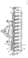
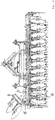
- an agricultural device 1 can be an attachment, the machine frame 2 of which can be attached to a tractor by means of a trestle 3 via a three-point linkage, not specifically shown, with upper and lower links.
- the attachment is also designed as a saddle-up device and can be linked to the tractor by means of a drawbar.
- the attachment 1 can be designed, for example, as a soil cultivation device in the form of a disc harrow with two rows of disc harrows and a subsequent post-processing unit. It goes without saying, however, that the attachment can also be designed differently, for example as a grassland device.
- the aforementioned machine frame 2 is how Figure 2 shows, designed to be foldable and can in particular comprise lateral machine sections which can be pivoted from a lowered working position into an upwardly pivoted inoperative or transport position.
- a folding axis 4 can be provided, which can extend, for example, lying, approximately parallel to the direction of travel.
- frame parts 5 that protrude laterally and / or are arranged on the right and left when viewed in the direction of travel can be folded down relative to an adjacent frame part 6, which can form a central frame part, for example.
- the machine frame 2 can basically be designed differently and for example comprise an elongated frame support spar 7 which is subdivided into at least two frame parts 5 and 6 that can be folded down relative to one another.
- Said frame support spar 7 can, for example, extend horizontally transversely to the direction of travel, wherein the two frame parts 5 and 6 in a folded position, in particular the lowered working position, can extend parallel to one another, in particular with their longitudinal center axes aligned with one another.
- Working tools 8, for example in the form of tillage tools such as the shown disc harrows or coulter discs, can be suspended on the frame support beam 7, whereby such working tools 8 can also be suspended on the foldable frame part so that the working tools 8 with the frame part 5 can be pivoted upwards.
- auxiliary units such as side boundary shields 9 can also be suspended.
- the foldable frame part can be pivoted upwards about the horizontal folding axis 4, which extends, for example, in the direction of travel, wherein the foldable frame part 5 can be pivoted by significantly more than 90 °, for example about 180 °.
- the two frame parts 5 and 6 can be brought from a side-by-side folded position, in which the two frame parts 5 and 6 can extend essentially along a common longitudinal axis and can connect to one another, into a second folded position pivoted by about 180 ° for this purpose of the two Frame parts lie essentially back to back against one another and / or extend overlapping one another.
- the folding axis 4 can be arranged between the two frame parts 5 and 6 which can be folded away relative to the longitudinal center axis of the two frame parts 5 and 6, in particular a little way above the two frame parts 5 and 6 when these are in the unfolded position Working position according to Fig. 7 (a) are located.
- the two frame parts 5 and 6 connected to one another by the folding axis 4 can have transversely projecting connecting brackets or flanges 10 at their adjacent end sections, each of which can form a bearing eye and are pivotably connected to one another by said folding axis 4.
- a pressure medium cylinder unit 11 which can comprise a piston rod 13 which can be extended out of a cylinder 12.
- Said pressure medium cylinder unit 11 is advantageously integrated into the interior of the machine frame 2, in particular accommodated in the interior of one of the frame parts 6 that can be folded down relative to one another.
- Said frame part 6 or its frame support spar section 7 can be designed as an elongated hollow profile with, for example, a tubular or U-shaped cross section, in the interior of which the pressure medium cylinder unit 11 is accommodated, cf. Fig. 7 .
- the pressure medium cylinder unit 11 can in this case be received essentially completely in the interior of the frame part 6, wherein the axial adjustment range of the piston rod 13 can also lie essentially completely in the interior of the frame part 6.
- the pressure medium cylinder unit 11 is advantageously rigidly attached to the frame part 6 or held immovable relative to the frame part 6.
- the pressure medium cylinder unit 11 can, for example, through the holding rod 14, with which, for example, pressure medium cylinder units 11 provided on opposite end sections, in particular their cylinders 12, can be supported against one another.
- the pressure cylinder unit 11 is also advantageously attached to the frame part 6 in a non-pivotable manner, for example by precisely fitting inside the frame part 6.
- essentially only the piston rod 13 can be moved axially relative to the frame part 6, namely extended and retracted.
- the piston rod 13 of the pressure medium cylinder unit 11 can be connected to the foldable frame part 5 via a folding lever part 15.
- Said folding lever part 15 can be a rigid rod part and / or articulated on the one hand on the piston rod 13 and on the other hand articulated on the frame part 5.
- the folding lever part 15 can be arranged and designed in such a way that the folding lever part 15 can be moved into the interior of the frame part 6 in which the pressure medium cylinder unit 11 is received.
- the folding lever part 15 can be provided to be retracted essentially completely into the frame part 6 in a folded position and to be extended essentially completely out of the frame part 6 in another folded position of the frame part 5, see comparative partial views (a) and ( b) the Fig. 7 .
- the piston rod 13 pushes the folding lever part 15 on the one hand out of the frame part 6 and on the other hand pulls it into the frame part 6.
- the adjusting movement of the piston rod 13 is converted into a pivoting movement of the frame part 5 via the folding lever part 15.
- Fig. 7 shows, two separate pistons 16 and 17 are attached to the piston rod 13 of the pressure medium cylinder unit 11, advantageously at a distance from one another, which can be acted upon by pressure medium chambers 18 and 19 and 20 and 21 which are separate from one another.
- the cylinder 12 of the pressure medium cylinder unit 11 can be divided by a partition 22 and divided into two cylinder chambers, which in turn are subdivided by the pistons 16 and 17 into two pressure medium chambers 18 and 19 or 20 and 21, respectively.
- the piston rod 13 passes through the named partition 22, it being possible for the passage to be sealed so that pressure medium chambers 19 and 20 are formed on both sides of the partition 22.
- the two pistons 16 and 17 can also be accommodated in cylinders that are completely separate from one another, both of which can be fixed to the frame part 6.
- the at least one cylinder 12 can be built onto or inserted into the frame part as a separate body. If necessary, the cylinder 12 can also be formed directly by walls of the frame part 6.
- the pressure medium chambers 18 and 20 or 19 and 21 located on corresponding sides of the two pistons 16 and 17 can each be connected in parallel to a pressure supply line or a pressure relief line in order to be pressurized or depressurized together, cf. Fig. 7 .
- the pressure medium chambers 19 and 21 located to the right of the pistons 16 and 17 can be connected to the line P (T), while the pressure medium chambers 18 and 20 located to the left of the pistons are connected in parallel to one another with the line or connection T (P) can.
- the two pressure medium chambers 19 and 21, which cause the piston rod 13 to extend are connected in parallel to one another and the two pressure medium chambers 18 and 20, which cause the piston rod 13 to retract, are also connected in parallel with one another.
- the pressure medium chambers 19 and 21 are pressurized and the pressure medium chambers 18 and 20 are depressurized at the same time, or vice versa, the pressure medium chambers 19 and 20 are depressurized and the pressure medium chambers 18 and 20 are pressurized. This can be done through the in Fig. 7 shown parallel connection, but also through separate pressurization connections or pressure sources.
- the piston rod 13 can advantageously be supported and / or guided in the area of the connecting joint to which the folding lever part 15 is articulated, in particular on the frame part 6 to which the pressure medium cylinder unit 11 is attached.
- the piston rod 13 can have a guide slide 23 which is guided on the frame part 6 so as to be longitudinally displaceable and supported in the transverse direction, for example by means of suitable sliding or roller bearings.
Landscapes
- Life Sciences & Earth Sciences (AREA)
- Engineering & Computer Science (AREA)
- Mechanical Engineering (AREA)
- Soil Sciences (AREA)
- Environmental Sciences (AREA)
- Agricultural Machines (AREA)
Claims (10)
- Appareil agricole, en particulier outil porté pouvant être monté sur un tracteur, avec un châssis de machine (2), qui comprend au moins deux parties de châssis (5, 6) pouvant être rabattues l'une vers l'autre, dans lequel une unité de cylindre à agent sous pression (11) est prévue pour rabattre le châssis de machine (2), qui est articulée sur les deux parties de châssis (5, 6) ou sur des leviers basculants (15) reliés à celles-ci, dans lequel l'unité de cylindre à agent sous pression (11) est intégrée au moins en partie dans l'intérieur d'une des deux parties de châssis (6), caractérisé en ce que l'unité de cylindre à agent sous pression (11) présente une tige de piston (13), sur laquelle sont fixés de manière espacée l'un de l'autre deux pistons (16, 17), ainsi que deux chambres d'agent sous pression (18, 19, 20, 21), qui soumettent à une action les deux pistons (16, 17) et ainsi la tige de piston (13) dans la même direction.
- Appareil agricole selon la revendication précédente, dans lequel l'unité de cylindre à agent sous pression (11) est logée sensiblement totalement, y compris un cylindre (12) et une tige de piston (13), dans l'intérieur de la partie de châssis (6) réalisée en tant que profil creux.
- Appareil agricole selon la revendication précédente, dans lequel l'unité de cylindre à agent sous pression (11) est réalisée de manière à exercer une action double et présente quatre chambres d'agent sous pression (18, 19, 20, 21), qui sont associées par paire aux deux pistons (16, 17) de telle manière que chacun des deux pistons (16, 17) peut être soumis à une action au choix dans la direction ou dans l'autre direction opposée et ainsi la tige de piston (13) peut être à la fois rentrée et sortie du fait de l'action sur les deux pistons (16, 17).
- Appareil agricole selon l'une quelconque des revendications précédentes, dans lequel l'unité de cylindre à agent sous pression (11) présente trois pistons (16, 17) ou plus, qui sont fixés de manière espacée les uns des autres sur une tige de piston (13) commune, dans lequel trois chambres d'agent sous pression (18, 20) ou plus sont prévues, qui soumettent à une action les trois pistons (16, 17) ou plus et ainsi la tige de piston (13) commune dans la même direction.
- Appareil agricole selon l'une quelconque des revendications précédentes, dans lequel toutes les chambres d'agent sous pression (18, 19, 20, 21), qui soumettent à une action les pistons (16, 17) et ainsi la tige de piston (13) dans la même direction, sont branchées de manière parallèle les unes par rapport aux autres et sont reliées à un raccord de pression P(T) commun et/ou à un raccord de décharge de pression T(P) commun.
- Appareil agricole selon l'une quelconque des revendications précédentes, dans lequel l'unité de cylindre à agent sous pression (11) est fixée sur une des parties de châssis (6) de manière solidaire axialement et sans pouvoir pivoter et est reliée à l'autre partie de châssis (5) à rabattre par rapport à celle-ci par une partie de levier basculant (15), qui est articulée sur l'unité de cylindre à agent de pression (11) et/ou est articulée sur l'autre partie de châssis (5).
- Appareil agricole selon la revendication précédente, dans lequel ladite partie de levier basculant (15) peut être rentrée dans la partie de châssis (6), dans laquelle l'unité de cylindre à agent sous pression (11) est disposée, dans lequel ladite partie de levier basculant (15) est logée sensiblement totalement dans la partie de châssis (6) en particulier dans une première position pliée de la partie de châssis (5) et la partie de levier basculant (15) est sortie sensiblement totalement hors de la partie de châssis (6) dans la position pliée opposée de la partie de châssis (5).
- Appareil agricole selon l'une quelconque des deux revendications précédentes, dans lequel la tige de piston (13) est montée, dans la zone de la liaison, à la partie de levier basculant (15), par un chariot de guidage (23) de manière à pouvoir coulisser longitudinalement et avec un appui transversal sur la partie de châssis (6), sur laquelle l'unité de cylindre à agent sous pression (11) est fixée.
- Appareil agricole selon l'une quelconque des revendications précédentes, dans lequel les deux parties de châssis (5, 6) pouvant pivoter l'une par rapport à l'autre peuvent pivoter l'une par rapport à l'autre sur une plage de pivotement de plus de 120°, en particulier d'environ 180°.
- Appareil agricole selon la revendication précédente, dans lequel l'unité de cylindre à agent sous pression (11) est prévue pour être active sans point mort sur la totalité de la plage de pivotement et/ou pour fournir sur la totalité de la plage de pivotement un déplacement de réglage de la partie de châssis (5, 6) l'une par rapport à l'autre.
Applications Claiming Priority (1)
| Application Number | Priority Date | Filing Date | Title |
|---|---|---|---|
| DE202016000649.6U DE202016000649U1 (de) | 2016-02-02 | 2016-02-02 | Landwirtschaftliches Gerät mit klappbarem Maschinenrahmen |
Publications (2)
| Publication Number | Publication Date |
|---|---|
| EP3205194A1 EP3205194A1 (fr) | 2017-08-16 |
| EP3205194B1 true EP3205194B1 (fr) | 2021-09-29 |
Family
ID=57956189
Family Applications (1)
| Application Number | Title | Priority Date | Filing Date |
|---|---|---|---|
| EP17154188.1A Active EP3205194B1 (fr) | 2016-02-02 | 2017-02-01 | Appareil agricole comprenant un châssis de machine repliable |
Country Status (2)
| Country | Link |
|---|---|
| EP (1) | EP3205194B1 (fr) |
| DE (1) | DE202016000649U1 (fr) |
Families Citing this family (2)
| Publication number | Priority date | Publication date | Assignee | Title |
|---|---|---|---|---|
| DE202018001461U1 (de) | 2018-03-19 | 2018-04-03 | Lemken Gmbh & Co. Kg | Schwenkbare Randscheibe |
| CN112021003B (zh) * | 2020-08-26 | 2024-03-08 | 宜兴博登泰科工业装备有限公司 | 对称耙组件及包含有对称耙组件的灭茬耙 |
Family Cites Families (6)
| Publication number | Priority date | Publication date | Assignee | Title |
|---|---|---|---|---|
| US3941194A (en) * | 1970-12-23 | 1976-03-02 | Orthman Manufacturing, Inc. | Folding tool bar having a transport brace |
| US4128131A (en) * | 1977-08-08 | 1978-12-05 | Deere & Company | Multiple section implement with beam raised and lowered on mast thereof |
| DE19817608A1 (de) * | 1997-05-17 | 1998-11-19 | Lemken Gmbh & Co Kg | Einklappbare Kreiselegge mit integrierten Schwenkzylindern |
| DE102004031821A1 (de) | 2004-07-01 | 2006-01-26 | Amazonen-Werke H. Dreyer Gmbh & Co. Kg | Hydraulische Betätigungsvorrichtung für eine landwirtschaftliche Bearbeitungsmaschine |
| DK2055164T3 (da) | 2007-11-02 | 2011-12-19 | Lemken Gmbh & Co Kg | Sammenklappelig kombination af landbrugsredskaber |
| US8820429B2 (en) * | 2011-03-30 | 2014-09-02 | Cnh Industrial America Llc | Fertilizer applicator with in-frame folding actuator for folding an outer frame member relative to an inner frame member |
-
2016
- 2016-02-02 DE DE202016000649.6U patent/DE202016000649U1/de not_active Expired - Lifetime
-
2017
- 2017-02-01 EP EP17154188.1A patent/EP3205194B1/fr active Active
Also Published As
| Publication number | Publication date |
|---|---|
| EP3205194A1 (fr) | 2017-08-16 |
| DE202016000649U1 (de) | 2017-05-03 |
Similar Documents
| Publication | Publication Date | Title |
|---|---|---|
| EP3122168B1 (fr) | Appareil de travail du sol comprenant un dispositif d'étrillage et d'aplanissement | |
| EP1813150B1 (fr) | Rampe de pulvérisation pour pulvérisateur agricole | |
| DE102012214615B4 (de) | Gezogene landwirtschaftliche Maschine mit Packereinheit | |
| AT511565A2 (de) | Automatische Erstkörper-Schnittbreiteneinstellung | |
| EP3205194B1 (fr) | Appareil agricole comprenant un châssis de machine repliable | |
| EP3242543B1 (fr) | Engin agricole à châssis de roulement supplémentaire | |
| DE4322263C5 (de) | Verfahren zur Vorbereitung eines auf einer Bodenfläche fahrenden Arbeitsfahrzeuges mit einem Arbeitsgerät für den Straßenbetrieb und Arbeitsgerät zur Anordnung an einem solchen Arbeitsfahrzeug | |
| DE202018106434U1 (de) | Landwirtschaftliches Anbaugerät | |
| EP1859665A1 (fr) | Machine agricole tractée à grande largeur de travail | |
| EP4252504A1 (fr) | Axe de réglage | |
| EP2591663B1 (fr) | Machine agricole | |
| DE10120845B4 (de) | Hydromechanische Steuerungsvorrichtung für eine mehrteilige landwirtschaftliche Arbeitsmaschine | |
| EP4272527A1 (fr) | Outil de montage pour l'usinage de champs | |
| EP3590322B1 (fr) | Appareil de travail agricole | |
| EP3354123B1 (fr) | Appareil de traitement du sol agricole | |
| DE202020103922U1 (de) | Landwirtschaftliche Maschine | |
| EP3367775B1 (fr) | Bâti d'engin agricole | |
| DE20219242U1 (de) | Heuwerbungsmaschine | |
| DE102010013470B4 (de) | Vorrichtung zum Verteilen von Saatgut und/oder Dünger | |
| EP4122304B1 (fr) | Machine de travail agricole | |
| DE202008014367U1 (de) | Heuwerbungsmaschine | |
| EP4062727B1 (fr) | Appareil agricole | |
| EP3800975A1 (fr) | Dispositif de réglage hydraulique | |
| EP3106010B1 (fr) | Dispositif de semis | |
| DE102024130073A1 (de) | Landwirtschaftliche Sämaschine und Verfahren zum Betreiben einer Sämaschine |
Legal Events
| Date | Code | Title | Description |
|---|---|---|---|
| PUAI | Public reference made under article 153(3) epc to a published international application that has entered the european phase |
Free format text: ORIGINAL CODE: 0009012 |
|
| STAA | Information on the status of an ep patent application or granted ep patent |
Free format text: STATUS: THE APPLICATION HAS BEEN PUBLISHED |
|
| AK | Designated contracting states |
Kind code of ref document: A1 Designated state(s): AL AT BE BG CH CY CZ DE DK EE ES FI FR GB GR HR HU IE IS IT LI LT LU LV MC MK MT NL NO PL PT RO RS SE SI SK SM TR |
|
| AX | Request for extension of the european patent |
Extension state: BA ME |
|
| STAA | Information on the status of an ep patent application or granted ep patent |
Free format text: STATUS: REQUEST FOR EXAMINATION WAS MADE |
|
| 17P | Request for examination filed |
Effective date: 20180208 |
|
| RBV | Designated contracting states (corrected) |
Designated state(s): AL AT BE BG CH CY CZ DE DK EE ES FI FR GB GR HR HU IE IS IT LI LT LU LV MC MK MT NL NO PL PT RO RS SE SI SK SM TR |
|
| GRAP | Despatch of communication of intention to grant a patent |
Free format text: ORIGINAL CODE: EPIDOSNIGR1 |
|
| STAA | Information on the status of an ep patent application or granted ep patent |
Free format text: STATUS: GRANT OF PATENT IS INTENDED |
|
| INTG | Intention to grant announced |
Effective date: 20210430 |
|
| GRAS | Grant fee paid |
Free format text: ORIGINAL CODE: EPIDOSNIGR3 |
|
| GRAA | (expected) grant |
Free format text: ORIGINAL CODE: 0009210 |
|
| STAA | Information on the status of an ep patent application or granted ep patent |
Free format text: STATUS: THE PATENT HAS BEEN GRANTED |
|
| AK | Designated contracting states |
Kind code of ref document: B1 Designated state(s): AL AT BE BG CH CY CZ DE DK EE ES FI FR GB GR HR HU IE IS IT LI LT LU LV MC MK MT NL NO PL PT RO RS SE SI SK SM TR |
|
| REG | Reference to a national code |
Ref country code: GB Ref legal event code: FG4D Free format text: NOT ENGLISH |
|
| REG | Reference to a national code |
Ref country code: DE Ref legal event code: R096 Ref document number: 502017011580 Country of ref document: DE |
|
| REG | Reference to a national code |
Ref country code: CH Ref legal event code: EP Ref country code: AT Ref legal event code: REF Ref document number: 1433407 Country of ref document: AT Kind code of ref document: T Effective date: 20211015 |
|
| REG | Reference to a national code |
Ref country code: IE Ref legal event code: FG4D Free format text: LANGUAGE OF EP DOCUMENT: GERMAN |
|
| REG | Reference to a national code |
Ref country code: LT Ref legal event code: MG9D |
|
| REG | Reference to a national code |
Ref country code: NO Ref legal event code: T2 Effective date: 20210929 |
|
| REG | Reference to a national code |
Ref country code: SE Ref legal event code: TRGR |
|
| PG25 | Lapsed in a contracting state [announced via postgrant information from national office to epo] |
Ref country code: HR Free format text: LAPSE BECAUSE OF FAILURE TO SUBMIT A TRANSLATION OF THE DESCRIPTION OR TO PAY THE FEE WITHIN THE PRESCRIBED TIME-LIMIT Effective date: 20210929 Ref country code: FI Free format text: LAPSE BECAUSE OF FAILURE TO SUBMIT A TRANSLATION OF THE DESCRIPTION OR TO PAY THE FEE WITHIN THE PRESCRIBED TIME-LIMIT Effective date: 20210929 Ref country code: BG Free format text: LAPSE BECAUSE OF FAILURE TO SUBMIT A TRANSLATION OF THE DESCRIPTION OR TO PAY THE FEE WITHIN THE PRESCRIBED TIME-LIMIT Effective date: 20211229 Ref country code: LT Free format text: LAPSE BECAUSE OF FAILURE TO SUBMIT A TRANSLATION OF THE DESCRIPTION OR TO PAY THE FEE WITHIN THE PRESCRIBED TIME-LIMIT Effective date: 20210929 Ref country code: RS Free format text: LAPSE BECAUSE OF FAILURE TO SUBMIT A TRANSLATION OF THE DESCRIPTION OR TO PAY THE FEE WITHIN THE PRESCRIBED TIME-LIMIT Effective date: 20210929 |
|
| REG | Reference to a national code |
Ref country code: NL Ref legal event code: MP Effective date: 20210929 |
|
| PG25 | Lapsed in a contracting state [announced via postgrant information from national office to epo] |
Ref country code: LV Free format text: LAPSE BECAUSE OF FAILURE TO SUBMIT A TRANSLATION OF THE DESCRIPTION OR TO PAY THE FEE WITHIN THE PRESCRIBED TIME-LIMIT Effective date: 20210929 Ref country code: GR Free format text: LAPSE BECAUSE OF FAILURE TO SUBMIT A TRANSLATION OF THE DESCRIPTION OR TO PAY THE FEE WITHIN THE PRESCRIBED TIME-LIMIT Effective date: 20211230 |
|
| PG25 | Lapsed in a contracting state [announced via postgrant information from national office to epo] |
Ref country code: IS Free format text: LAPSE BECAUSE OF FAILURE TO SUBMIT A TRANSLATION OF THE DESCRIPTION OR TO PAY THE FEE WITHIN THE PRESCRIBED TIME-LIMIT Effective date: 20220129 Ref country code: SK Free format text: LAPSE BECAUSE OF FAILURE TO SUBMIT A TRANSLATION OF THE DESCRIPTION OR TO PAY THE FEE WITHIN THE PRESCRIBED TIME-LIMIT Effective date: 20210929 Ref country code: RO Free format text: LAPSE BECAUSE OF FAILURE TO SUBMIT A TRANSLATION OF THE DESCRIPTION OR TO PAY THE FEE WITHIN THE PRESCRIBED TIME-LIMIT Effective date: 20210929 Ref country code: PT Free format text: LAPSE BECAUSE OF FAILURE TO SUBMIT A TRANSLATION OF THE DESCRIPTION OR TO PAY THE FEE WITHIN THE PRESCRIBED TIME-LIMIT Effective date: 20220131 Ref country code: PL Free format text: LAPSE BECAUSE OF FAILURE TO SUBMIT A TRANSLATION OF THE DESCRIPTION OR TO PAY THE FEE WITHIN THE PRESCRIBED TIME-LIMIT Effective date: 20210929 Ref country code: NL Free format text: LAPSE BECAUSE OF FAILURE TO SUBMIT A TRANSLATION OF THE DESCRIPTION OR TO PAY THE FEE WITHIN THE PRESCRIBED TIME-LIMIT Effective date: 20210929 Ref country code: ES Free format text: LAPSE BECAUSE OF FAILURE TO SUBMIT A TRANSLATION OF THE DESCRIPTION OR TO PAY THE FEE WITHIN THE PRESCRIBED TIME-LIMIT Effective date: 20210929 Ref country code: EE Free format text: LAPSE BECAUSE OF FAILURE TO SUBMIT A TRANSLATION OF THE DESCRIPTION OR TO PAY THE FEE WITHIN THE PRESCRIBED TIME-LIMIT Effective date: 20210929 Ref country code: AL Free format text: LAPSE BECAUSE OF FAILURE TO SUBMIT A TRANSLATION OF THE DESCRIPTION OR TO PAY THE FEE WITHIN THE PRESCRIBED TIME-LIMIT Effective date: 20210929 |
|
| REG | Reference to a national code |
Ref country code: DE Ref legal event code: R097 Ref document number: 502017011580 Country of ref document: DE |
|
| PG25 | Lapsed in a contracting state [announced via postgrant information from national office to epo] |
Ref country code: DK Free format text: LAPSE BECAUSE OF FAILURE TO SUBMIT A TRANSLATION OF THE DESCRIPTION OR TO PAY THE FEE WITHIN THE PRESCRIBED TIME-LIMIT Effective date: 20210929 |
|
| PLBE | No opposition filed within time limit |
Free format text: ORIGINAL CODE: 0009261 |
|
| STAA | Information on the status of an ep patent application or granted ep patent |
Free format text: STATUS: NO OPPOSITION FILED WITHIN TIME LIMIT |
|
| 26N | No opposition filed |
Effective date: 20220630 |
|
| PG25 | Lapsed in a contracting state [announced via postgrant information from national office to epo] |
Ref country code: MC Free format text: LAPSE BECAUSE OF FAILURE TO SUBMIT A TRANSLATION OF THE DESCRIPTION OR TO PAY THE FEE WITHIN THE PRESCRIBED TIME-LIMIT Effective date: 20210929 |
|
| REG | Reference to a national code |
Ref country code: CH Ref legal event code: PL |
|
| REG | Reference to a national code |
Ref country code: BE Ref legal event code: MM Effective date: 20220228 |
|
| GBPC | Gb: european patent ceased through non-payment of renewal fee |
Effective date: 20220201 |
|
| PG25 | Lapsed in a contracting state [announced via postgrant information from national office to epo] |
Ref country code: LU Free format text: LAPSE BECAUSE OF NON-PAYMENT OF DUE FEES Effective date: 20220201 |
|
| PG25 | Lapsed in a contracting state [announced via postgrant information from national office to epo] |
Ref country code: SI Free format text: LAPSE BECAUSE OF FAILURE TO SUBMIT A TRANSLATION OF THE DESCRIPTION OR TO PAY THE FEE WITHIN THE PRESCRIBED TIME-LIMIT Effective date: 20210929 |
|
| PG25 | Lapsed in a contracting state [announced via postgrant information from national office to epo] |
Ref country code: LI Free format text: LAPSE BECAUSE OF NON-PAYMENT OF DUE FEES Effective date: 20220228 Ref country code: IE Free format text: LAPSE BECAUSE OF NON-PAYMENT OF DUE FEES Effective date: 20220201 Ref country code: GB Free format text: LAPSE BECAUSE OF NON-PAYMENT OF DUE FEES Effective date: 20220201 Ref country code: CH Free format text: LAPSE BECAUSE OF NON-PAYMENT OF DUE FEES Effective date: 20220228 |
|
| PG25 | Lapsed in a contracting state [announced via postgrant information from national office to epo] |
Ref country code: BE Free format text: LAPSE BECAUSE OF NON-PAYMENT OF DUE FEES Effective date: 20220228 |
|
| REG | Reference to a national code |
Ref country code: AT Ref legal event code: MM01 Ref document number: 1433407 Country of ref document: AT Kind code of ref document: T Effective date: 20220201 |
|
| PG25 | Lapsed in a contracting state [announced via postgrant information from national office to epo] |
Ref country code: AT Free format text: LAPSE BECAUSE OF NON-PAYMENT OF DUE FEES Effective date: 20220201 |
|
| P01 | Opt-out of the competence of the unified patent court (upc) registered |
Effective date: 20230613 |
|
| PG25 | Lapsed in a contracting state [announced via postgrant information from national office to epo] |
Ref country code: HU Free format text: LAPSE BECAUSE OF FAILURE TO SUBMIT A TRANSLATION OF THE DESCRIPTION OR TO PAY THE FEE WITHIN THE PRESCRIBED TIME-LIMIT; INVALID AB INITIO Effective date: 20170201 |
|
| PG25 | Lapsed in a contracting state [announced via postgrant information from national office to epo] |
Ref country code: SM Free format text: LAPSE BECAUSE OF FAILURE TO SUBMIT A TRANSLATION OF THE DESCRIPTION OR TO PAY THE FEE WITHIN THE PRESCRIBED TIME-LIMIT Effective date: 20210929 Ref country code: MK Free format text: LAPSE BECAUSE OF FAILURE TO SUBMIT A TRANSLATION OF THE DESCRIPTION OR TO PAY THE FEE WITHIN THE PRESCRIBED TIME-LIMIT Effective date: 20210929 Ref country code: CY Free format text: LAPSE BECAUSE OF FAILURE TO SUBMIT A TRANSLATION OF THE DESCRIPTION OR TO PAY THE FEE WITHIN THE PRESCRIBED TIME-LIMIT Effective date: 20210929 |
|
| PG25 | Lapsed in a contracting state [announced via postgrant information from national office to epo] |
Ref country code: TR Free format text: LAPSE BECAUSE OF FAILURE TO SUBMIT A TRANSLATION OF THE DESCRIPTION OR TO PAY THE FEE WITHIN THE PRESCRIBED TIME-LIMIT Effective date: 20210929 |
|
| PG25 | Lapsed in a contracting state [announced via postgrant information from national office to epo] |
Ref country code: MT Free format text: LAPSE BECAUSE OF FAILURE TO SUBMIT A TRANSLATION OF THE DESCRIPTION OR TO PAY THE FEE WITHIN THE PRESCRIBED TIME-LIMIT Effective date: 20210929 |
|
| PGFP | Annual fee paid to national office [announced via postgrant information from national office to epo] |
Ref country code: CZ Payment date: 20250117 Year of fee payment: 9 |
|
| PGFP | Annual fee paid to national office [announced via postgrant information from national office to epo] |
Ref country code: SE Payment date: 20260224 Year of fee payment: 10 |
|
| PGFP | Annual fee paid to national office [announced via postgrant information from national office to epo] |
Ref country code: NO Payment date: 20260226 Year of fee payment: 10 Ref country code: DE Payment date: 20260218 Year of fee payment: 10 |
|
| PGFP | Annual fee paid to national office [announced via postgrant information from national office to epo] |
Ref country code: IT Payment date: 20260219 Year of fee payment: 10 |
|
| PGFP | Annual fee paid to national office [announced via postgrant information from national office to epo] |
Ref country code: FR Payment date: 20260225 Year of fee payment: 10 |