EP3205200A1 - Tête faucheuse avec cassette de fil - Google Patents
Tête faucheuse avec cassette de fil Download PDFInfo
- Publication number
- EP3205200A1 EP3205200A1 EP17155718.4A EP17155718A EP3205200A1 EP 3205200 A1 EP3205200 A1 EP 3205200A1 EP 17155718 A EP17155718 A EP 17155718A EP 3205200 A1 EP3205200 A1 EP 3205200A1
- Authority
- EP
- European Patent Office
- Prior art keywords
- line
- cartridge
- housing
- gear
- brake
- Prior art date
- Legal status (The legal status is an assumption and is not a legal conclusion. Google has not performed a legal analysis and makes no representation as to the accuracy of the status listed.)
- Granted
Links
Images





























Classifications
-
- A—HUMAN NECESSITIES
- A01—AGRICULTURE; FORESTRY; ANIMAL HUSBANDRY; HUNTING; TRAPPING; FISHING
- A01G—HORTICULTURE; CULTIVATION OF VEGETABLES, FLOWERS, RICE, FRUIT, VINES, HOPS OR SEAWEED; FORESTRY; WATERING
- A01G3/00—Cutting implements specially adapted for horticultural purposes; Delimbing standing trees
- A01G3/06—Hand-held edge trimmers or shears for lawns
-
- A—HUMAN NECESSITIES
- A01—AGRICULTURE; FORESTRY; ANIMAL HUSBANDRY; HUNTING; TRAPPING; FISHING
- A01D—HARVESTING; MOWING
- A01D34/00—Mowers; Mowing apparatus of harvesters
- A01D34/01—Mowers; Mowing apparatus of harvesters characterised by features relating to the type of cutting apparatus
- A01D34/412—Mowers; Mowing apparatus of harvesters characterised by features relating to the type of cutting apparatus having rotating cutters
- A01D34/416—Flexible line cutters
-
- A—HUMAN NECESSITIES
- A01—AGRICULTURE; FORESTRY; ANIMAL HUSBANDRY; HUNTING; TRAPPING; FISHING
- A01D—HARVESTING; MOWING
- A01D34/00—Mowers; Mowing apparatus of harvesters
- A01D34/01—Mowers; Mowing apparatus of harvesters characterised by features relating to the type of cutting apparatus
- A01D34/412—Mowers; Mowing apparatus of harvesters characterised by features relating to the type of cutting apparatus having rotating cutters
- A01D34/416—Flexible line cutters
- A01D34/4161—Means for feeding cutter line
-
- A—HUMAN NECESSITIES
- A01—AGRICULTURE; FORESTRY; ANIMAL HUSBANDRY; HUNTING; TRAPPING; FISHING
- A01D—HARVESTING; MOWING
- A01D34/00—Mowers; Mowing apparatus of harvesters
- A01D34/01—Mowers; Mowing apparatus of harvesters characterised by features relating to the type of cutting apparatus
- A01D34/412—Mowers; Mowing apparatus of harvesters characterised by features relating to the type of cutting apparatus having rotating cutters
- A01D34/416—Flexible line cutters
- A01D34/4161—Means for feeding cutter line
- A01D34/4162—Means for feeding cutter line automatically
-
- A—HUMAN NECESSITIES
- A01—AGRICULTURE; FORESTRY; ANIMAL HUSBANDRY; HUNTING; TRAPPING; FISHING
- A01D—HARVESTING; MOWING
- A01D34/00—Mowers; Mowing apparatus of harvesters
- A01D34/01—Mowers; Mowing apparatus of harvesters characterised by features relating to the type of cutting apparatus
- A01D34/412—Mowers; Mowing apparatus of harvesters characterised by features relating to the type of cutting apparatus having rotating cutters
- A01D34/416—Flexible line cutters
- A01D34/4161—Means for feeding cutter line
- A01D34/4163—Means for feeding cutter line by triggered line feedout, e.g. bump-feeding
-
- A—HUMAN NECESSITIES
- A01—AGRICULTURE; FORESTRY; ANIMAL HUSBANDRY; HUNTING; TRAPPING; FISHING
- A01D—HARVESTING; MOWING
- A01D34/00—Mowers; Mowing apparatus of harvesters
- A01D34/01—Mowers; Mowing apparatus of harvesters characterised by features relating to the type of cutting apparatus
- A01D34/412—Mowers; Mowing apparatus of harvesters characterised by features relating to the type of cutting apparatus having rotating cutters
- A01D34/63—Mowers; Mowing apparatus of harvesters characterised by features relating to the type of cutting apparatus having rotating cutters having cutters rotating about a vertical axis
- A01D34/67—Mowers; Mowing apparatus of harvesters characterised by features relating to the type of cutting apparatus having rotating cutters having cutters rotating about a vertical axis hand-guided by a walking operator
-
- A—HUMAN NECESSITIES
- A01—AGRICULTURE; FORESTRY; ANIMAL HUSBANDRY; HUNTING; TRAPPING; FISHING
- A01D—HARVESTING; MOWING
- A01D34/00—Mowers; Mowing apparatus of harvesters
- A01D34/835—Mowers; Mowing apparatus of harvesters specially adapted for particular purposes
-
- A—HUMAN NECESSITIES
- A01—AGRICULTURE; FORESTRY; ANIMAL HUSBANDRY; HUNTING; TRAPPING; FISHING
- A01G—HORTICULTURE; CULTIVATION OF VEGETABLES, FLOWERS, RICE, FRUIT, VINES, HOPS OR SEAWEED; FORESTRY; WATERING
- A01G3/00—Cutting implements specially adapted for horticultural purposes; Delimbing standing trees
- A01G3/06—Hand-held edge trimmers or shears for lawns
- A01G3/067—Motor-driven shears for lawns
Definitions
- the present invention relates to trimmers and, more particularly, to trimmer heads for string trimmers.
- trimmers are used to cut grass and weeds, and are often used to edge around trees, near fences and walls, and along landscape borders.
- Conventional string trimmers include an elongated shaft with a rotating element or gear head near the end of the elongated shaft, and a spool or string head is attached to the gear head.
- the string head includes a monofilament line (i.e., trimmer line) that is rotated by the gear head for cutting and trimming along landscaped areas, fences, and walls.
- a cartridge for a trimmer head may be provided.
- the trimmer head may include a housing assembly with a top member drivingly engaging a drive shaft of a trimmer.
- the cartridge may generally include a cartridge housing operable to support a line; and a brake assembly operable in a braking condition to selectively apply a force to the line to prevent line from being dispensed.
- the line cartridge may be assembled as a unit.
- the brake assembly may include a brake member pivotable relative to the cartridge housing and operable in a braking condition to selectively apply a pinching force to a trimmer line to prevent the line from being dispensed.
- the brake assembly may include a gear selectively operable between a release condition, in which the gear is rotatable to allow line to be dispensed, and a braking condition, in which the gear is inhibited from rotating to prevent the line from being dispensed.
- a cartridge may generally include a cartridge housing operable to support a line to be dispensed, the cartridge housing including a first housing portion fixed in an axial position, and a second housing portion movable along the axis relative to the first housing portion; and a brake assembly operable in a braking condition to selectively apply a force to the line to prevent line from being dispensed, the brake assembly including a brake member operable between the braking condition, in which the brake member prevents line from being dispensed, and a release condition, movement of the second housing portion along the axis operating the brake member between the braking condition and the release condition, the second housing portion being selectively movable in an auto-feed mode, in cooperation with a flyweight, and in a bump-feed mode, when a bump member engages a surface.
- a trimmer may generally include a motor operable to drive a drive shaft; a trimmer head including a housing assembly with a top member drivingly engaging the drive shaft for rotation about an axis; and a cartridge supported for rotation about the axis, the cartridge including a cartridge housing operable to support a line, and a brake assembly operable in a braking condition to selectively apply a force to the line to prevent line from being dispensed, the brake assembly being operable in an auto-feed mode, in cooperation with a flyweight, and in a bump-feed mode, when a bump member engages a surface.
- An aspect of invention provides a cartridge for a trimmer head, the trimmer head including a housing assembly with a top member drivingly engaging a drive shaft of a trimmer, the cartridge comprising: a cartridge housing operable to support a line; and a brake assembly operable in a braking condition to selectively apply a force to the line to prevent line from being dispensed.
- the brake assembly may be operable between the braking condition portion and a release condition in an auto-feed mode, in cooperation with a flyweight, and in a bump-feed mode, when a bump member engages a surface.
- the cartridge housing, the line and the brake assembly may be assembled as a unit.
- the brake assembly may include a brake member pivotable relative to the cartridge housing between a braking position, in which the brake member applies a pinching force to the line to prevent line from being dispensed, and a release position.
- the cartridge may be supportable for rotation about an axis.
- the brake member may be pivotable about a pivot axis extending transverse to the axis.
- the brake member may be pivotable about a pivot axis.
- the cartridge housing may include a housing portion defining the pivot axis. In the braking position, the braking member may cooperate with the housing portion to apply a pinching force to the line.
- the brake member may be pivotable about a pivot axis
- the cartridge housing may include a first housing portion defining the pivot axis, and a second housing portion movable relative to the pivot axis, movement of the second housing portion causing pivoting movement of the brake member.
- the brake assembly may include a first gear having a first gripping portion engaging the line and a first gear portion, and a second gear having a second gripping portion engaging the line, a second gear portion intermeshed with the first gear portion, and a stop member, the brake assembly being selectively operable between the braking condition, in which the stop member engages the second housing portion to inhibit rotation of the first gear and the second gear to prevent line from being dispensed, and a release condition, in which the stop member is disengaged and the first gear and the second gear are rotatable to allow line to be dispensed.
- the cartridge housing may include a first housing portion supporting the first gear and the second gear, and a second housing portion movable relative to the first housing portion between a stop position corresponding to the braking condition, in which the stop member engages the second housing portion to inhibit rotation of the second gear and the first gear, and a release position, in which the stop member is disengaged to allow rotation of the first gear and the second gear.
- the brake assembly may include a brake member operable between the braking condition, in which the brake member prevents line from being dispensed, and a release condition, wherein the cartridge is supportable for rotation about an axis, and wherein the cartridge housing may include a first housing portion supporting the brake member and being fixed in an axial position, and a second housing movable along the axis, movement of the second housing portion operating the brake member between the braking condition and the release condition.
- the housing assembly may pivotably support the flyweight, the flyweight optionally having a ramped surface.
- the second housing portion may have a lifting projection, in the auto-feed mode, the flyweight being pivotable to engage the ramped surface with the lifting projection to move the second housing portion.
- the cartridge housing may include the bump member, the bump member being connected to the second housing portion for movement with the second housing portion.
- the first housing portion may define a guide slot for the line, the guide slot extending about the axis, and the second housing portion may have a circumferential surface cooperating with the first housing portion to maintain the line in the guide slot.
- the cartridge housing may also include a top member and a bottom member cooperating to define a cavity, and the first housing portion may include a radially-extending divider plate dividing the cavity into a first line compartment for a first line and a second line compartment for a second line.
- the brake assembly may include a first brake member operable in the braking condition to prevent a first line from being dispensed, and a second brake member operable in the braking condition to prevent a second line from being dispensed.
- a trimmer comprising: a motor operable to drive a drive shaft; a trimmer head including a housing assembly with a top member drivingly engaging the drive shaft for rotation about an axis; and a cartridge supported for rotation about the axis, the cartridge including a cartridge housing operable to support a line, and a brake assembly operable in a braking condition to selectively apply a force to the line to prevent line from being dispensed, the brake assembly being operable in an auto-feed mode, in cooperation with a flyweight, and in a bump-feed mode, when a bump member engages a surface.
- Figs. 2-4 illustrate a line cartridge 10 supportable in a trimmer head 14 for use on an exemplary string trimmer T shown in Fig. 1 .
- the trimmer T generally includes a shaft S with a handle H toward one end and a motor housing M enclosing an electric motor (not shown) with a motor-driven output or drive shaft (not shown) for connection to a trimmer head on the other end.
- Various powered trimmers e.g., battery-powered, gas-powered, etc. may be used with the trimmer head 10.
- the line cartridge 10 is assembled as a unit to be installed into the housing assembly of the trimmer head 14 and onto the trimmer T.
- the line cartridge 10 is assembled with one or more trimmer lines L and is operable to dispense the line(s) L until expended. Once the lines L are expended, the line cartridge 10 is removed and may be disposed. A replacement line cartridge 10 may then be installed to continue use of the trimmer T.
- the trimmer head 14 is rotatable about an axis A and includes a housing assembly provided by a top member 18 and a bottom cover member 22.
- the housing members 18, 22 are connected by fingers 26 engageable in complementary openings 30.
- the housing members 18, 22 define a cavity 34 generally for receiving a spool (not shown) supporting trimmer line or the cartridge 10.
- Line openings 38 are defined in the side wall of the housing assembly, and a bump opening 42 is defined in the bottom cover member 22.
- the top member 18 is drivingly connected to the drive shaft.
- the top member 18 includes (see Fig. 5 ) a plate 46 with a depending central post 50 having an annular rim 54.
- the central post 50 receives a fastener 58 and supports a spring 62.
- pivot posts 66 also depend from the plate 46 and are spaced radially from the central post 50. Stop members 70 are positioned around the posts 66.
- the illustrated trimmer head 14 is an auto-feed trimmer head.
- the line cartridge 10 is operable to dispense line L in an auto-feed mode (when supported in the auto-feed trimmer head 14) or in a bump-feed mode (when supported in the auto-feed trimmer head 14 or when supported in a trimmer head without auto-feed).
- flyweights 74 are pivotably supported on the pivot posts 66.
- Each flyweight 74 includes a pivot portion 78 and a weighted arm 82 and a ramp 86 extending from the pivot portion 78.
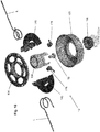
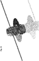
- the line cartridge 10 includes (see Figs. 18-19 ) a cartridge housing assembly provided by a top plate 104 and a bottom cover 108 connected to define (see Fig. 3 ) a cavity 110.
- the top plate 104 defines (see Fig. 19 ) a central opening 112 and includes flexible fingers 116 engageable with a rim 120 on the bottom cover 108 to connect the components.
- the cartridge housing assembly houses the cartridge body.
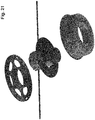
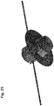
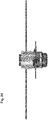
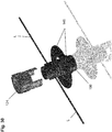
- the cartridge body includes (see Figs. 22-30 ) a slide tube 124 movable along the axis A.
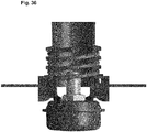
- the spring 62 (see Fig. 3 ) engages the slide tube 124 to bias the slide tube 124 downwardly.
- lift projections 128 are formed on the exterior of the slide tube 124, and each projection 128 is engageable by the ramp 86 on the associated flyweight 74 to cause axial upward movement of the slide tube 124.
- Line slots 132 are defined through the slide tube 124 to accommodate the lines L during axial movement of the slide tube 124.
- the slide tube 124 has a cylindrical inner surface 136, and, at the bottom, axial slots 140, 144.
- line guide members 148 define guide slots 152 for the lines L.
- the guide members 148 cooperate with the inner surface 136 of the slide tube 124 to maintain the each line L in the associated guide slot 152.
- the guide slots 152 provide a number of windings (e.g., four) about the guide members 148. The number of windings and/or the structure of the guide slots 152 may be determined based on the desired effect (e.g., friction) on the lines L during dispensing, retention, etc.
- the guide members 148 provide a radially-extending divider plate 156 to divide the cavity 110 into (see Fig. 3 ) upper and lower line compartments 160 for line to be dispensed (not shown). Each guide member 148 defines a line opening 164 communicating between the associated guide slot 152 and line compartment 160. Each line L is stored in a separate compartment 160 and travels through a separate guide slot 152 to avoid interference between the lines L.
- the guide members 148 cooperate to define a pair of pivot openings 168, and the divider plate 156 defines opposite slots 170.
- the guide members 148 have an upper edge 172 engageable with the rim 54 on the top member 18 to inhibit relative axial movement between the guide members 148 and the top member 18.
- the slide tube 124 is thus axially movable relative to the guide members 148.
- brake members 176 are pivotably supported by the guide members 148.
- Each brake member 176 includes a pivot post 180 supported in the associated pivot opening 168 for movement about a pivot axis PA.
- Each pivot axis PA is transverse to the axis A and, in the illustrated construction, intersects the axis A.
- each brake member 176 pivots about the same pivot axis PA.
- each brake member 176 may be supported with the associated pivot axis PA being different from the other and/or oriented differently relative to the axis A.
- An arm 184 extends from the pivot post 180, and a line slot 188 is defined in the pivot post 180.
- a pinch edge 192 is provided at an end of the line slot 188.
- the associated line L is selectively “pinched” between the pinch edge 192 and cooperating structure of the guide member 148.
- the pinch edge 192 is selectively engageable with the associated line L to apply a force to retain or “brake” the line L and disengageable from the line L to allow movement of or "release” the line L (e.g., under the effect of centrifugal force during rotation of the trimmer head 14).
- a bump member 196 is connected to the bottom end of the slide tube 124 for movement with the slide tube 124.
- the guide members 148 and the assembly of the bump member 196 and the slide tube 124 cooperate to capture each other.
- the axial slots 140 in the slide tube 124 receive the portions of the guide members 148 defining the pivot openings 168 and the supported pivot posts 180. Meanwhile, portions of the slide tube 124 extend through the slots 170 in the divider plate 156 for connection to the bump member 196.
- arm slots 200 and pivot recesses 204 are defined in the rim 208 of the bump member 196.
- the end of each arm 184 of an associated brake member 176 is received in an arm slot 200 and in an axial slot 144 on the slide tube 124.
- Axial movement of the guide tube 124 and the bump member 196 causes pivoting movement of the brake members 176.
- the pivot recesses 204 accommodate the pivot posts 180 when the bump member 196 is moved axially upwardly.
- the line cartridge 10 is positioned in the trimmer head 14 with the housing members 18, 22 connected (see Fig. 3 ).
- the spring 62 biases the slide tube 124 and the bump member 196 downwardly relative to the guide members 148, causing the brake members 176 to pivot to the braking position, in which the pinch edge 192 engages the line L to prevent dispensing of the line L.
- the line cartridge 10 is operable in an auto-feed mode (with the auto-feed trimmer head 14) or in a bump-feed mode.
- the slide tube 124 and the bump member 196 are moved upwardly, causing the brake members 176 to pivot to the release position, in which the pinch edge 192 disengages and releases the line L to allow the line L to be dispensed under centrifugal force.
- the rotational speed of the trimmer head 14 decreases.
- the flyweights 74 pivot inwardly, disengaging the ramps 86 from the lift projections 128 (see Fig. 7 ).
- the slide tube 124 and the bump member 196 move downwardly under the biasing force of the spring 62.
- the brake members 176 pivot to the braking position so the pinch edge 192 re-engages the line L to pinch or brake the line L and prevent further dispensing.
- the bump member 196 In a bump-feed mode, the bump member 196 is engaged against the ground and pushed upwardly. Upward movement of the bump member 196 causes the slide member 124 to move upwardly against the force of the spring 62 and causes the brake members 176 to pivot to the release position and release the line L. Centrifugal force causes the line L to be drawn out of the line cartridge 10.
- the spring 62 biases the slide tube 124 and the bump member 196 downwardly. This downward movement causes the brake members 176 to pivot to the braking position so the pinch edge 192 re-engages the line L to pinch or brake the line L and prevent further dispensing.
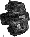
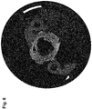
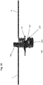
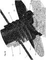
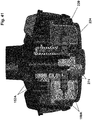
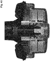
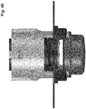
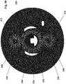
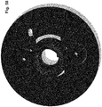
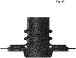
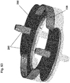
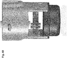
- Figs. 40-76 illustrate an alternative construction of a line cartridge 10A supportable in the trimmer head 14 for use on a trimmer, such as the exemplary string trimmer T shown in Fig. 1 .
- the line cartridge 10A is similar to the line cartridge 10 described above and illustrated in Figs. 2-39 , and common elements have the common reference numbers "A".
- the line cartridge 10A is operable to dispense line L in an auto-feed mode (when supported in the auto-feed trimmer head 14) or in a bump-feed mode (when supported in the auto-feed trimmer head 14 or when supported in a trimmer head without auto-feed).
- the line cartridge 10A includes (see Figs. 40-43 ) a cartridge housing assembly, provided by a top plate 104A and a bottom cover 108A, housing a cartridge body.
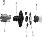
- the cartridge body includes (see Fig. 52 ) a slide tube 124A, a line guide member 220 (similar to the line guide members 148) and a bump member 196A.
- the line cartridge 10A includes a gear brake assembly 224 and a gear support 228 cooperating with the line guide member 220 to support the gear brake assembly 224.
- the gear brake assembly 224 includes a number of gears (e.g., three) including a main gear 232 intermeshed with a cooperating gear 236 for each line L to be dispensed.
- Each gear 232, 236 has a gear portion 240 and a gripping portion 244.
- the gear portions 240 interengage to coordinate movement of the gears 232, 236.
- a line L is threaded between the gripping portions 244 of adjacent gears 232, 236.
- the gripping portions 244 are configured (e.g., have a roughened surface, a frictional material, combinations thereof, etc.) to apply friction to the line L.
- the gear brake assembly 224 is operable between a release condition, in which the gears 232, 236 are free to rotate to allow the lines L to be dispensed, and a braking condition, in which the gears 232, 236 are prevented from rotating to prevent lines L from being dispensed.
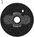
- a stop assembly 248 (see Figs. 66-70 ) is provided between the gear brake assembly 224 and adjacent structure to selectively place the gear brake assembly 224 in the release condition and in the braking condition.
- the gear brake assembly 224 (e.g., the main gear 232) includes a number of stop members 252 selectively engageable with one or more complementary stop members 256 on the adjacent structure.
- the main gear 232 includes a number first stop members 252 a (e.g., three) each selectively engageable with a stop member 256 a on the slide tube 124A.
- the illustrated main gear 232 also includes a number of second stop members 252 b (e.g., three) each selectively engageable with a stop member 256 b on the bump member 196A.
- the stop members 252, 256 are formed with the main gear 232 and the slide tube 124A/the bump member 196A.
- the structure of the stop members 252, 256 may be separate from and connected to the main gear 232 and the slide tube 124A/the bump member 196A.
- the main gear 232 may define an opening receiving a pin providing the stop member(s) 252, 256.
- the stop members 252 are equally spaced (by about 120°) about the circumference of the main gear 232.
- the number and position of the stop member(s) 252, 256 may be different (e.g., the main gear 232 may include fewer or more than three stop members 252).
- the main gear 232 may include only a first stop 252, engageable with the stop member 256 on the adjacent structure (e.g., the slide tube 124A).
- the main gear 232 may include one first stop 252 a and one second stop 252 b
- the slide tube 124A and the bump member 196A may include a number of complementary stop members 256 a , 256 b (e.g., one, two, three, etc.).
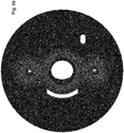
- the line guide member 220 is (see Figs. 56 and 61 ) a unitary member defining guide slots 152A with a number of windings (e.g., three) for the lines L. As shown in Figs. 54-55 , the guide member 220 cooperates with the gear support 228 to rotatably support the gears 232, 236 of the gear brake assembly 224.
- the guide member 220 defines (see Figs. 56 and 61 ) a central pocket 260 receiving the main gear 232 and a central post 264 on which the main gear 232 is rotatably guided.
- a side pocket 268 receives each gear 236 and has a post 272 for rotatably guiding the gear 236.
- a line passage 276 passes between adjacent gears 232, 236 from the associated compartment 160A to the associated guide slot 152A.
- the gear support 228 cooperates (see Figs. 54-55 ) with the pockets 260, 268 to house the gear brake assembly 224.
- Projections 280 are received in openings 284 in the posts 272 to connect the gear support 228 and the guide member 220.
- a central opening 288 provides access to the stop member(s) 252 b on the main gear 232.
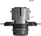
- the guide member 220 defines (see Fig. 59 ) a groove 292 communicating with an opening 296 providing access to the stop member(s) 252 a on the main gear 232. As shown in Fig. 44 , the stop member 256 a on the slide tube 124A extends in the groove 292 and through the opening 296 to be positioned to be selectively engaged by the stop member(s) 252 a .
- the bump member 196A is connected to the bottom end of the slide tube 124A for movement with the slide tube 124A relative to the guide member 220.
- the guide member 220 and the assembly of the bump member 196A and the slide tube 124A cooperate to capture each other.
- portions of the slide tube 124A extend through the slots 170A in the divider plate 156A for connection to the bump member 196A.
- Barbed projections 300 on the bump member 196A are received in openings 304 to connect the bump member 196A and the slide tube 124A.
- the stop member 256 b extends in a slot 308 in the slide tube 124A.
- the line cartridge 10A is positioned in the trimmer head 14 with the housing members 18, 22 connected (see Fig. 40 ).
- the spring (not shown but similar to the spring 62 in Fig. 3 ) biases the slide tube 124A and the bump member 196A downwardly relative to the guide member 220, causing the stop assembly 248 to be engaged to prevent dispensing of the line L.
- one first stop member 252 a on the main gear 232 is engaged with the stop member 256 a on the slide tube 124A.
- the line cartridge 10A is operable in an auto-feed mode (with the auto-feed trimmer head 14) or in a bump-feed mode.
- the slide tube 124A and the bump member 196A are moved upwardly, causing the stop member 252 a to be disengaged from the stop member 256 a .
- centrifugal force causes the lines L to be dispensed, thereby causing the gears 232, 236 to rotate.
- the amount of line L dispensed during each dispensing action is limited. Specifically, after the stop member 252 a disengages the stop member 256 a , the main gear 232 rotates an amount (e.g., about 60°) as line L is dispensed until one second stop member 252 b engages with the stop member 256 b of the bump member 196A, now in a raised position as a result of sliding of the bump member 196A with the slide tube 124A.
- an amount e.g., about 60°
- the stops 252 b , 256 b remain engaged until the slide tube 124A returns to its initial axial position (e.g., in an auto-feed mode, by slowing the trimmer head 14 (due to the increased amount of dispensed line L or reducing power to the motor) to disengage the ramps 86A from the lift projections 128A; in a bump-feed mode, by disengaging the bump member 196A from the ground).
- the bump member 196A also moves downwardly, disengaging the stop members 252 b , 256 b .
- the main gear 232 is able to rotate (again, about 60°), and line L is dispensed until one stop member 252 a engages the stop member 256 a on the slide tube 124A.
- the number and position of the stop member(s) 252 on the main gear 232 are selected based on the desired amount of rotation (e.g., 90°, 120°, 180°, 360°, etc.) during dispensing of the lines L which correlates to the amount of line L being dispensed. As described above, in the illustrated construction, during each dispensing action, the length of line L dispensed is limited by limited rotation of the main gear 232 (e.g., about 120°, as illustrated).
- dispensing of line L may not be limited by the stop assembly 248.
- the stop assembly 248 dispensing of line L may not be limited by the stop assembly 248.
- the main gear 232 is free to rotate and line L can be dispensed until the slide tube 124A returns to the position with the stop members 252, 256 engaged.
- the invention may thus provide a line cartridge assembled as a unit and useable with a trimmer head.
- the line cartridge may be useable in an auto-fee mode and in a bump-feed mode.
Landscapes
- Life Sciences & Earth Sciences (AREA)
- Environmental Sciences (AREA)
- Biodiversity & Conservation Biology (AREA)
- Ecology (AREA)
- Forests & Forestry (AREA)
- Coating Apparatus (AREA)
- Apparatus For Making Beverages (AREA)
- Harvester Elements (AREA)
Applications Claiming Priority (1)
| Application Number | Priority Date | Filing Date | Title |
|---|---|---|---|
| US201662293855P | 2016-02-11 | 2016-02-11 |
Publications (2)
| Publication Number | Publication Date |
|---|---|
| EP3205200A1 true EP3205200A1 (fr) | 2017-08-16 |
| EP3205200B1 EP3205200B1 (fr) | 2022-07-20 |
Family
ID=58017975
Family Applications (1)
| Application Number | Title | Priority Date | Filing Date |
|---|---|---|---|
| EP17155718.4A Active EP3205200B1 (fr) | 2016-02-11 | 2017-02-10 | Tête faucheuse avec cassette de fil |
Country Status (5)
| Country | Link |
|---|---|
| US (1) | US20170231153A1 (fr) |
| EP (1) | EP3205200B1 (fr) |
| CN (1) | CN107047087A (fr) |
| AU (1) | AU2017200966B2 (fr) |
| CA (1) | CA2957687A1 (fr) |
Families Citing this family (13)
| Publication number | Priority date | Publication date | Assignee | Title |
|---|---|---|---|---|
| USD830798S1 (en) * | 2016-06-03 | 2018-10-16 | Andreas Stihl Ag & Co. Kg | Battery powered trimmer |
| USD874891S1 (en) * | 2017-08-04 | 2020-02-11 | Husqvarna Ab | Guard shield for a trimmer |
| USD889219S1 (en) | 2017-08-04 | 2020-07-07 | Husqvarna Ab | Air outlet for a trimmer |
| USD867833S1 (en) * | 2017-10-18 | 2019-11-26 | Changzhou Globe Co., Ltd. | String trimmer head |
| CN109691318B (zh) * | 2017-10-20 | 2021-06-18 | 南京德朔实业有限公司 | 打草头和用于打草的工具系统 |
| WO2019192201A1 (fr) * | 2018-04-02 | 2019-10-10 | 南京德朔实业有限公司 | Coupe-bordure |
| USD1029594S1 (en) * | 2021-04-23 | 2024-06-04 | Zhejiang Safun Industrial Co., Ltd. | Grass trimmer |
| USD988101S1 (en) * | 2021-07-01 | 2023-06-06 | Huajie Dong | Handheld lawn mower |
| USD966059S1 (en) * | 2021-09-15 | 2022-10-11 | Ningbo Winbay Technology Co., Ltd. | Cordless string trimmer |
| US12477978B2 (en) * | 2022-03-18 | 2025-11-25 | Techtronic Cordless Gp | Power tool and accessory mount device |
| US12532806B2 (en) | 2023-02-14 | 2026-01-27 | Techtronic Cordless Gp | Power tool and compact power feed trimmer head |
| CN116439001A (zh) * | 2023-02-27 | 2023-07-18 | 永康市欣森工贸有限公司 | 一种具有防卡死机构的打草机及其使用方法 |
| USD1074347S1 (en) * | 2024-05-08 | 2025-05-13 | Jiangyun Xu | Lawn mower |
Citations (5)
| Publication number | Priority date | Publication date | Assignee | Title |
|---|---|---|---|---|
| US4138810A (en) * | 1977-04-20 | 1979-02-13 | Pittinger Sr Charles B | Torsional vibration filament feed system |
| US4285128A (en) * | 1979-11-16 | 1981-08-25 | Benchmark Tool Company | Spool feed mechanism for line fed grass trimmer |
| EP0824854A2 (fr) * | 1996-08-23 | 1998-02-25 | Fernando R. Iacona | Tête pour faucheuse à filament |
| US20010023542A1 (en) * | 1999-12-20 | 2001-09-27 | Brant Ronald G. | String trimmer head |
| US6519857B1 (en) * | 2001-11-21 | 2003-02-18 | Proulx Manufacturing, Inc. | Fixed line head for flexible line rotary trimmers |
Family Cites Families (4)
| Publication number | Priority date | Publication date | Assignee | Title |
|---|---|---|---|---|
| US4169311A (en) * | 1976-11-17 | 1979-10-02 | Evenson Dale D | Vegetation cutting apparatus |
| US5311665A (en) * | 1990-11-16 | 1994-05-17 | Diatop Corporation | Cutting head for a cord type mower |
| US8910387B2 (en) * | 2008-04-22 | 2014-12-16 | George Everett Alliss | String trimmer head configuration and method |
| US20140150267A1 (en) * | 2012-12-03 | 2014-06-05 | Techtronic Outdoor Products Technology Limited | Head for a trimmer and attachment therefor |
-
2017
- 2017-02-10 US US15/430,077 patent/US20170231153A1/en not_active Abandoned
- 2017-02-10 EP EP17155718.4A patent/EP3205200B1/fr active Active
- 2017-02-10 CA CA2957687A patent/CA2957687A1/fr not_active Abandoned
- 2017-02-13 CN CN201710075886.XA patent/CN107047087A/zh active Pending
- 2017-02-13 AU AU2017200966A patent/AU2017200966B2/en active Active
Patent Citations (5)
| Publication number | Priority date | Publication date | Assignee | Title |
|---|---|---|---|---|
| US4138810A (en) * | 1977-04-20 | 1979-02-13 | Pittinger Sr Charles B | Torsional vibration filament feed system |
| US4285128A (en) * | 1979-11-16 | 1981-08-25 | Benchmark Tool Company | Spool feed mechanism for line fed grass trimmer |
| EP0824854A2 (fr) * | 1996-08-23 | 1998-02-25 | Fernando R. Iacona | Tête pour faucheuse à filament |
| US20010023542A1 (en) * | 1999-12-20 | 2001-09-27 | Brant Ronald G. | String trimmer head |
| US6519857B1 (en) * | 2001-11-21 | 2003-02-18 | Proulx Manufacturing, Inc. | Fixed line head for flexible line rotary trimmers |
Also Published As
| Publication number | Publication date |
|---|---|
| CN107047087A (zh) | 2017-08-18 |
| CA2957687A1 (fr) | 2017-08-11 |
| US20170231153A1 (en) | 2017-08-17 |
| EP3205200B1 (fr) | 2022-07-20 |
| AU2017200966B2 (en) | 2019-10-03 |
| AU2017200966A1 (en) | 2017-08-31 |
Similar Documents
| Publication | Publication Date | Title |
|---|---|---|
| EP3205200A1 (fr) | Tête faucheuse avec cassette de fil | |
| CN109691290B (zh) | 打草机 | |
| CN105815029B (zh) | 打草机 | |
| CN204069756U (zh) | 打草机 | |
| US4161820A (en) | Apparatus for cutting vegetation | |
| CN112088641B (zh) | 打草头 | |
| EP1446002B1 (fr) | Tete de fil fixee pour appareils de coupe rotatifs a fil flexible | |
| US5063673A (en) | Vegetation cutters | |
| US6854185B1 (en) | Vegetation trimmer apparatus | |
| WO2015172744A1 (fr) | Machine à couper l'herbe et procédé de dévidage pour machine à couper l'herbe | |
| EP4353066A1 (fr) | Tête de tondeuse à fil | |
| US20060254061A1 (en) | Vegetation trimmer apparatus | |
| JP4995563B2 (ja) | 刈払い機用ロータリカッタ | |
| US4316325A (en) | Weed cutting apparatus | |
| US20060254060A1 (en) | Vegetation trimmer apparatus | |
| JPH0254046B2 (fr) | ||
| CA2068192A1 (fr) | Dispositif pour couper la vegetation | |
| CN111837590A (zh) | 打草头和打草机 | |
| AU7176181A (en) | Apparatus for cutting vegetation |
Legal Events
| Date | Code | Title | Description |
|---|---|---|---|
| PUAI | Public reference made under article 153(3) epc to a published international application that has entered the european phase |
Free format text: ORIGINAL CODE: 0009012 |
|
| STAA | Information on the status of an ep patent application or granted ep patent |
Free format text: STATUS: THE APPLICATION HAS BEEN PUBLISHED |
|
| AK | Designated contracting states |
Kind code of ref document: A1 Designated state(s): AL AT BE BG CH CY CZ DE DK EE ES FI FR GB GR HR HU IE IS IT LI LT LU LV MC MK MT NL NO PL PT RO RS SE SI SK SM TR |
|
| AX | Request for extension of the european patent |
Extension state: BA ME |
|
| STAA | Information on the status of an ep patent application or granted ep patent |
Free format text: STATUS: REQUEST FOR EXAMINATION WAS MADE |
|
| 17P | Request for examination filed |
Effective date: 20180216 |
|
| RBV | Designated contracting states (corrected) |
Designated state(s): AL AT BE BG CH CY CZ DE DK EE ES FI FR GB GR HR HU IE IS IT LI LT LU LV MC MK MT NL NO PL PT RO RS SE SI SK SM TR |
|
| STAA | Information on the status of an ep patent application or granted ep patent |
Free format text: STATUS: EXAMINATION IS IN PROGRESS |
|
| 17Q | First examination report despatched |
Effective date: 20200922 |
|
| RAP1 | Party data changed (applicant data changed or rights of an application transferred) |
Owner name: TTI (MACAO COMMERCIAL OFFSHORE) LIMITED |
|
| RAP1 | Party data changed (applicant data changed or rights of an application transferred) |
Owner name: TECHTRONIC OUTDOOR PRODUCTS TECHNOLOGY LIMITED |
|
| GRAP | Despatch of communication of intention to grant a patent |
Free format text: ORIGINAL CODE: EPIDOSNIGR1 |
|
| STAA | Information on the status of an ep patent application or granted ep patent |
Free format text: STATUS: GRANT OF PATENT IS INTENDED |
|
| INTG | Intention to grant announced |
Effective date: 20220428 |
|
| GRAS | Grant fee paid |
Free format text: ORIGINAL CODE: EPIDOSNIGR3 |
|
| GRAA | (expected) grant |
Free format text: ORIGINAL CODE: 0009210 |
|
| STAA | Information on the status of an ep patent application or granted ep patent |
Free format text: STATUS: THE PATENT HAS BEEN GRANTED |
|
| AK | Designated contracting states |
Kind code of ref document: B1 Designated state(s): AL AT BE BG CH CY CZ DE DK EE ES FI FR GB GR HR HU IE IS IT LI LT LU LV MC MK MT NL NO PL PT RO RS SE SI SK SM TR |
|
| REG | Reference to a national code |
Ref country code: CH Ref legal event code: EP |
|
| REG | Reference to a national code |
Ref country code: DE Ref legal event code: R096 Ref document number: 602017059576 Country of ref document: DE |
|
| REG | Reference to a national code |
Ref country code: AT Ref legal event code: REF Ref document number: 1504951 Country of ref document: AT Kind code of ref document: T Effective date: 20220815 |
|
| REG | Reference to a national code |
Ref country code: IE Ref legal event code: FG4D |
|
| REG | Reference to a national code |
Ref country code: LT Ref legal event code: MG9D |
|
| REG | Reference to a national code |
Ref country code: NL Ref legal event code: MP Effective date: 20220720 |
|
| PG25 | Lapsed in a contracting state [announced via postgrant information from national office to epo] |
Ref country code: SE Free format text: LAPSE BECAUSE OF FAILURE TO SUBMIT A TRANSLATION OF THE DESCRIPTION OR TO PAY THE FEE WITHIN THE PRESCRIBED TIME-LIMIT Effective date: 20220720 Ref country code: RS Free format text: LAPSE BECAUSE OF FAILURE TO SUBMIT A TRANSLATION OF THE DESCRIPTION OR TO PAY THE FEE WITHIN THE PRESCRIBED TIME-LIMIT Effective date: 20220720 Ref country code: PT Free format text: LAPSE BECAUSE OF FAILURE TO SUBMIT A TRANSLATION OF THE DESCRIPTION OR TO PAY THE FEE WITHIN THE PRESCRIBED TIME-LIMIT Effective date: 20221121 Ref country code: NO Free format text: LAPSE BECAUSE OF FAILURE TO SUBMIT A TRANSLATION OF THE DESCRIPTION OR TO PAY THE FEE WITHIN THE PRESCRIBED TIME-LIMIT Effective date: 20221020 Ref country code: NL Free format text: LAPSE BECAUSE OF FAILURE TO SUBMIT A TRANSLATION OF THE DESCRIPTION OR TO PAY THE FEE WITHIN THE PRESCRIBED TIME-LIMIT Effective date: 20220720 Ref country code: LV Free format text: LAPSE BECAUSE OF FAILURE TO SUBMIT A TRANSLATION OF THE DESCRIPTION OR TO PAY THE FEE WITHIN THE PRESCRIBED TIME-LIMIT Effective date: 20220720 Ref country code: LT Free format text: LAPSE BECAUSE OF FAILURE TO SUBMIT A TRANSLATION OF THE DESCRIPTION OR TO PAY THE FEE WITHIN THE PRESCRIBED TIME-LIMIT Effective date: 20220720 Ref country code: FI Free format text: LAPSE BECAUSE OF FAILURE TO SUBMIT A TRANSLATION OF THE DESCRIPTION OR TO PAY THE FEE WITHIN THE PRESCRIBED TIME-LIMIT Effective date: 20220720 Ref country code: ES Free format text: LAPSE BECAUSE OF FAILURE TO SUBMIT A TRANSLATION OF THE DESCRIPTION OR TO PAY THE FEE WITHIN THE PRESCRIBED TIME-LIMIT Effective date: 20220720 |
|
| REG | Reference to a national code |
Ref country code: AT Ref legal event code: MK05 Ref document number: 1504951 Country of ref document: AT Kind code of ref document: T Effective date: 20220720 |
|
| PG25 | Lapsed in a contracting state [announced via postgrant information from national office to epo] |
Ref country code: PL Free format text: LAPSE BECAUSE OF FAILURE TO SUBMIT A TRANSLATION OF THE DESCRIPTION OR TO PAY THE FEE WITHIN THE PRESCRIBED TIME-LIMIT Effective date: 20220720 Ref country code: IS Free format text: LAPSE BECAUSE OF FAILURE TO SUBMIT A TRANSLATION OF THE DESCRIPTION OR TO PAY THE FEE WITHIN THE PRESCRIBED TIME-LIMIT Effective date: 20221120 Ref country code: HR Free format text: LAPSE BECAUSE OF FAILURE TO SUBMIT A TRANSLATION OF THE DESCRIPTION OR TO PAY THE FEE WITHIN THE PRESCRIBED TIME-LIMIT Effective date: 20220720 Ref country code: GR Free format text: LAPSE BECAUSE OF FAILURE TO SUBMIT A TRANSLATION OF THE DESCRIPTION OR TO PAY THE FEE WITHIN THE PRESCRIBED TIME-LIMIT Effective date: 20221021 |
|
| REG | Reference to a national code |
Ref country code: DE Ref legal event code: R097 Ref document number: 602017059576 Country of ref document: DE |
|
| PG25 | Lapsed in a contracting state [announced via postgrant information from national office to epo] |
Ref country code: SM Free format text: LAPSE BECAUSE OF FAILURE TO SUBMIT A TRANSLATION OF THE DESCRIPTION OR TO PAY THE FEE WITHIN THE PRESCRIBED TIME-LIMIT Effective date: 20220720 Ref country code: RO Free format text: LAPSE BECAUSE OF FAILURE TO SUBMIT A TRANSLATION OF THE DESCRIPTION OR TO PAY THE FEE WITHIN THE PRESCRIBED TIME-LIMIT Effective date: 20220720 Ref country code: DK Free format text: LAPSE BECAUSE OF FAILURE TO SUBMIT A TRANSLATION OF THE DESCRIPTION OR TO PAY THE FEE WITHIN THE PRESCRIBED TIME-LIMIT Effective date: 20220720 Ref country code: CZ Free format text: LAPSE BECAUSE OF FAILURE TO SUBMIT A TRANSLATION OF THE DESCRIPTION OR TO PAY THE FEE WITHIN THE PRESCRIBED TIME-LIMIT Effective date: 20220720 Ref country code: AT Free format text: LAPSE BECAUSE OF FAILURE TO SUBMIT A TRANSLATION OF THE DESCRIPTION OR TO PAY THE FEE WITHIN THE PRESCRIBED TIME-LIMIT Effective date: 20220720 |
|
| PLBE | No opposition filed within time limit |
Free format text: ORIGINAL CODE: 0009261 |
|
| STAA | Information on the status of an ep patent application or granted ep patent |
Free format text: STATUS: NO OPPOSITION FILED WITHIN TIME LIMIT |
|
| PG25 | Lapsed in a contracting state [announced via postgrant information from national office to epo] |
Ref country code: SK Free format text: LAPSE BECAUSE OF FAILURE TO SUBMIT A TRANSLATION OF THE DESCRIPTION OR TO PAY THE FEE WITHIN THE PRESCRIBED TIME-LIMIT Effective date: 20220720 Ref country code: EE Free format text: LAPSE BECAUSE OF FAILURE TO SUBMIT A TRANSLATION OF THE DESCRIPTION OR TO PAY THE FEE WITHIN THE PRESCRIBED TIME-LIMIT Effective date: 20220720 |
|
| 26N | No opposition filed |
Effective date: 20230421 |
|
| PG25 | Lapsed in a contracting state [announced via postgrant information from national office to epo] |
Ref country code: AL Free format text: LAPSE BECAUSE OF FAILURE TO SUBMIT A TRANSLATION OF THE DESCRIPTION OR TO PAY THE FEE WITHIN THE PRESCRIBED TIME-LIMIT Effective date: 20220720 |
|
| PG25 | Lapsed in a contracting state [announced via postgrant information from national office to epo] |
Ref country code: SI Free format text: LAPSE BECAUSE OF FAILURE TO SUBMIT A TRANSLATION OF THE DESCRIPTION OR TO PAY THE FEE WITHIN THE PRESCRIBED TIME-LIMIT Effective date: 20220720 |
|
| PG25 | Lapsed in a contracting state [announced via postgrant information from national office to epo] |
Ref country code: MC Free format text: LAPSE BECAUSE OF FAILURE TO SUBMIT A TRANSLATION OF THE DESCRIPTION OR TO PAY THE FEE WITHIN THE PRESCRIBED TIME-LIMIT Effective date: 20220720 |
|
| REG | Reference to a national code |
Ref country code: CH Ref legal event code: PL |
|
| REG | Reference to a national code |
Ref country code: BE Ref legal event code: MM Effective date: 20230228 |
|
| PG25 | Lapsed in a contracting state [announced via postgrant information from national office to epo] |
Ref country code: LU Free format text: LAPSE BECAUSE OF NON-PAYMENT OF DUE FEES Effective date: 20230210 Ref country code: LI Free format text: LAPSE BECAUSE OF NON-PAYMENT OF DUE FEES Effective date: 20230228 Ref country code: CH Free format text: LAPSE BECAUSE OF NON-PAYMENT OF DUE FEES Effective date: 20230228 |
|
| REG | Reference to a national code |
Ref country code: IE Ref legal event code: MM4A |
|
| PG25 | Lapsed in a contracting state [announced via postgrant information from national office to epo] |
Ref country code: IE Free format text: LAPSE BECAUSE OF NON-PAYMENT OF DUE FEES Effective date: 20230210 |
|
| PG25 | Lapsed in a contracting state [announced via postgrant information from national office to epo] |
Ref country code: BE Free format text: LAPSE BECAUSE OF NON-PAYMENT OF DUE FEES Effective date: 20230228 |
|
| PG25 | Lapsed in a contracting state [announced via postgrant information from national office to epo] |
Ref country code: IT Free format text: LAPSE BECAUSE OF FAILURE TO SUBMIT A TRANSLATION OF THE DESCRIPTION OR TO PAY THE FEE WITHIN THE PRESCRIBED TIME-LIMIT Effective date: 20220720 |
|
| PG25 | Lapsed in a contracting state [announced via postgrant information from national office to epo] |
Ref country code: BG Free format text: LAPSE BECAUSE OF FAILURE TO SUBMIT A TRANSLATION OF THE DESCRIPTION OR TO PAY THE FEE WITHIN THE PRESCRIBED TIME-LIMIT Effective date: 20220720 |
|
| PG25 | Lapsed in a contracting state [announced via postgrant information from national office to epo] |
Ref country code: BG Free format text: LAPSE BECAUSE OF FAILURE TO SUBMIT A TRANSLATION OF THE DESCRIPTION OR TO PAY THE FEE WITHIN THE PRESCRIBED TIME-LIMIT Effective date: 20220720 |
|
| PG25 | Lapsed in a contracting state [announced via postgrant information from national office to epo] |
Ref country code: CY Free format text: LAPSE BECAUSE OF FAILURE TO SUBMIT A TRANSLATION OF THE DESCRIPTION OR TO PAY THE FEE WITHIN THE PRESCRIBED TIME-LIMIT; INVALID AB INITIO Effective date: 20170210 |
|
| PG25 | Lapsed in a contracting state [announced via postgrant information from national office to epo] |
Ref country code: HU Free format text: LAPSE BECAUSE OF FAILURE TO SUBMIT A TRANSLATION OF THE DESCRIPTION OR TO PAY THE FEE WITHIN THE PRESCRIBED TIME-LIMIT; INVALID AB INITIO Effective date: 20170210 |
|
| PG25 | Lapsed in a contracting state [announced via postgrant information from national office to epo] |
Ref country code: TR Free format text: LAPSE BECAUSE OF FAILURE TO SUBMIT A TRANSLATION OF THE DESCRIPTION OR TO PAY THE FEE WITHIN THE PRESCRIBED TIME-LIMIT Effective date: 20220720 |
|
| PGFP | Annual fee paid to national office [announced via postgrant information from national office to epo] |
Ref country code: GB Payment date: 20260227 Year of fee payment: 10 |
|
| PGFP | Annual fee paid to national office [announced via postgrant information from national office to epo] |
Ref country code: DE Payment date: 20260227 Year of fee payment: 10 |
|
| PGFP | Annual fee paid to national office [announced via postgrant information from national office to epo] |
Ref country code: FR Payment date: 20260225 Year of fee payment: 10 |